1
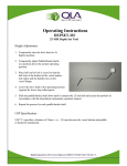
80mm Standard
Figure 24
STEP #4: While gently pressing back on the gage shaft to avoid hitting the
vessel rim or centering ring, lower the dissolution drive head until it touches
the top of the standard or spacer, release the gage shaft and observe the
reading on the gage. The difference between the reading at the bottom of the
vessel and the top of the vessel is the displacement.
STEP #5: Rotate the gage 90 Degrees and then repeat steps 2 thru 4.
STEP #6: Repeat steps 2 thru 5 for each shaft location.
4.12
Calculating Vessel Verticality
A simple calculation has been performed to determine that the maximum
allowable displacement over a distance of 80mm at a 1 Degree angle shall not
exceed 1.36mm.
Example: The dial indicator moved clockwise from 40 to 5. The displacement or
total indicated reading is .50mm. This vessel Passed.
Example: The dial indicator moved counter clockwise from 40 to 30. The
displacement or total indicated reading is 1.00mm. This vessel Passed.
Example: The dial indicator moved counter clockwise from 40 to 5. The
displacement or total indicated reading is 3.50mm. This vessel Failed.
5.0
Qualification and Validation
Prior to shipment, the kit is calibrated and includes a Certificate of Calibration and
Traceability. The complete kit should be returned to QLA for recalibration once a year.
VALTOL-ASTM, Rev 2.0
Page 22