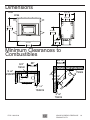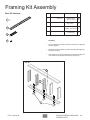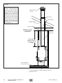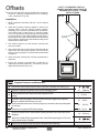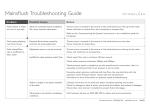
1
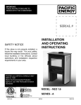
IMPORTANT: THESE INSTRUCTIONS ARE TO REMAIN WITH THE HOMEOWNER. PLEASE SAVE THESE INSTRUCTIONS. SAFETY NOTICE If this fireplace is not properly installed, a house fire may result. For your safety, follow the installation instructions. Contact local building or fire officials about restrictions and installation inspection requirements in your area. SERIAL # INSTALLATION AND OPERATING INSTRUCTIONS TESTED and LISTED to CAN/ULC S610-M87 AND UL 127 Meets the Environmental Protection Agency's July 1990 Particulate Emission Standards MODEL: FP25, FP25AR 160415-28 ©PACIFIC ENERGY FIREPLACE PRODUCTS LTD. - 2014 ZERO CLEARANCE WOOD FIREPLACE FP25 5055.7618 Contents Safety and Maintenance.............................................................. 3 Maintenance Checks.................................................................... 4 Creosote........................................................................................ 5 NOTE: WE STRONGLY R E C O M M E N D T H AT SMOKE DETECTORS BE INSTALLED. If smoke detectors have been previously installed, you may notice that they are operating more frequently. This may be due to curing of fireplace paint or fumes caused by accidentally leaving the fire door open. Do not disconnect the detectors. If necessary, relocate them to reduce their sensitivity. Formation and Need for Removal...........................................................5 Chimney Fires.........................................................................................5 In the event of a Chimney Fire................................................................5 Preventing a Chimney Fire......................................................................5 Wood Selection.......................................................................................5 How to Test Your Wood...........................................................................5 Operation....................................................................................... 6 Lighting for the First Time........................................................................6 Lighting a Fire..........................................................................................6 Normal Operation....................................................................................6 Restarting After Extended or Overnight Burns........................................6 Overfiring.................................................................................................7 Average Heat Output Calculation............................................................7 Proper Draft.............................................................................................7 Ash Removal...........................................................................................7 Disposal of Ashes....................................................................................7 Blower Operation.....................................................................................7 Baffle Removal............................................................................. 7 Secondary Air Box Cleaning....................................................................7 Glass Cleaning........................................................................................8 Blower Replacement...............................................................................8 Firebrick Installation Instructions.............................................................9 SAFETY NOTICE: If this fireplace is not properly installed, a house fire may result. For your safety, follow the installation instructions. Contact local building or fire officials about restrictions and installation inspection requirements in your area. Please read this entire manual before you install and use your new room heater. Failure to follow instructions may result in property damage, bodily injury, or even death. Fireplace Installation.................................................................. 10 Crate Removal.......................................................................................10 Locating The FP25 Fireplace................................................................10 Clearances............................................................................................10 Procedure:.............................................................................................10 Dimensions..................................................................................11 Minimum Clearances to Combustibles.....................................11 Minimum Framing Dimensions................................................. 12 Framing Kit Assembly................................................................ 13 Listed Chimney and Chimney Connector..............................................15 Chase/Enclosure...................................................................................15 Mobile Home Installation:......................................................................15 Offsets......................................................................................... 16 Combustion Air........................................................................... 17 Framing....................................................................................... 18 Typical Installation.................................................................................18 Floor Protector............................................................................ 19 Safety Strip............................................................................................19 Blower Wiring........................................................................................19 Mantel Clearances...................................................................... 20 Remote Heat Duct Installation................................................... 21 Electrical Wiring.....................................................................................22 Appendix A.................................................................................. 24 Troubleshooting.....................................................................................24 Understanding & Operating Your Pacific Energy Fireplace...................25 Replacement Parts................................................................................26 Label Location.......................................................................................27 Label......................................................................................................27 2 ©PACIFIC ENERGY FIREPLACE PRODUCTS LTD. FP25 160415-28 Safety and Maintenance 1. Burn only, dry and well seasoned cord wood. The denser or heavier the wood when dry, the greater its heat value. This is why hardwoods are generally preferred. Green or wet wood should not be used, it will reduce heat output, as well as, contribute significantly to creosote buildup. WARNING: NEVER USE CHEMICALS OR ANY OTHER VOLATILE LIQUID TO START A FIRE. DO NOT BURN GARBAGE OR FLAMMABLE FLUIDS SUCH AS GASOLINE, NAPHTHA, OR ENGINE OIL. WE STRONGLY RECOMMEND THAT SMOKE DETECTORS BE INSTALLED. 2. Maintain a 1"(25mm) minimum ash base for best results. The area where boost combustion air enters the firebox must be kept clear of excessive ash buildup which will block air flow. This area is at the front of the firebox. Remove ashes if excess buildup occurs. Embers may roll out of the firebox door opening and create a fire hazard. 3. If glass becomes darkened through slow burning or poor wood, it can be cleaned with fireplace glass cleaner when the fireplace is cold. Never scrape with an object that might scratch the glass. The type and amount of deposit on the glass is a good indication of the flue pipe and chimney buildup. A light brown dusty deposit that is easily wiped off usually indicates good combustion and dry, well-seasoned wood and therefore relatively clean pipes and chimney. On the other hand, a black greasy deposit that is difficult to remove is a result of wet and green wood and too slow a burning rate. This heavy deposit is building up as quickly in the chimney. 4. Establish a routine for the fuel, wood burning and firing technique. Check daily for creosote buildup until experience shows how often you need to clean to be safe. WARNING: ONLY USE MATERIALS AND COMPONENTS SUPPLIED OR SPECIFIED BY MANUFACTURER WHEN DOING MAINTENANCE OR REPLACEMENTS. DO NOT USE A FIREPLACE INSERT OR OTHER PRODUCTS NOT SPECIFIED FOR USE WITH THIS FIREPLACE. 5. DOOR GASKETS - The gasket used by Pacific Energy (3/4"(19mm) round high density fibreglass rope) requires only light pressure to seal. This will prolong seal life. It is important that the door seal be maintained in good condition. Periodically inspect seals and replace if necessary with WODC.NEODGKIT. 6. DOOR GLASS - Replacement glass can be obtained from your dealer. Use 18”(457mm) x 10-1/4”(260mm) x 5 mm ceramic glass only. FP25 160415-28 WARNING: DO NOT SUBSTITUTE GLASS WITH ANY OTHER TYPE MATERIAL OTHER THAN CERAMIC GLASS WARNING: DO NOT SLAM LOADING DOOR OR OTHERWISE IMPACT GLASS. WHEN CLOSING DOOR, MAKE SURE THAT NO LOGS PROTRUDE TO IMPACT THE GLASS. IF THE GLASS GETS CRACKED OR BROKEN, IT MUST BE REPLACED BEFORE USING THE FIREPLACE. WARNING: OVER FIRING THE APPLIANCE WILL SHORTEN THE LIFE OF THE PRODUCT. FAILURE TO R ECTIFY AN OVER FIRING CONDITION CAN BE HAZARDOUS AND MAY VOID THE MANUFACTURER'S WARRANTY. To remove broken glass,remove the door gasket and clean out the screw heads. Remove the screws that hold the retainers and remove the retainers, noting position for re-assembly. Remove all particles of glass . Be careful as they are very sharp. Install new glass complete with gasket. Replace retainers, screws and gasket. CAUTION: - DO NOT OVERTIGHTEN - TIGHTEN SCREWS HAND TIGHT - DO NOT CLEAN GLASS WHEN HOT - DO NOT USE ABRASIVE CLEANERS ON GLASS 7. Do not store wood within heater installation clearances, or within the space required for fuel loading and ash removal. Keep the area around the heater clean and free of loose combustibles, furniture, newspapers, etc. 8. Be aware that the hotter the fire, the less creosote is deposited. Weekly cleaning may be necessary in mild weather, even though monthly cleaning is usually enough in the coldest months when burning rates are higher. 9. Instruct all members of your family on the safe operation of the heater. Ensure they have enough knowledge of the entire system if they are expected to operate it. Stress the section on chimney fires and the importance of following the steps outlined "In Case of Chimney Fire". 10.Inspect and clean your chimney system at the beginning of the burning season before your first fire and at least every two months during the burning season. Inspect the interior and exterior of the pipe for defects and/or damage. Remove and inspect the rain cap. Refer to the chimney system manufacturer's installation instructions for the procedure to remove and or replace any necessary components to the chimney system. 11.Maintain a distance of 48"(1.22m) to all combustible materials in the room unless otherwise specidifed. (see Floor Protector section on page 19 for Floor Protection dimensions) ©PACIFIC ENERGY FIREPLACE PRODUCTS LTD. 3 Maintenance Checks Check the following parts for damage such as cracks, excessive corrosion, burned out sections and excessive warping: (See website for descriptions and more detail) Weekly: - Firebrick - Visual, for cracking. - Door Gasket - sagging, displacement, damage. Monthly - Brick rail tabs and brick rails. - Air riser tube in the back of the firebox. - Back side of airwash chamber. - Baffle locking pin. - Boost tube cover. When Cleaning the Chimney System: - Top baffle board/blanket. - Baffle. - Top heat shield and mounting bolt. - Baffle Gasket. - Brick Rails. - Manifold. Blowers: - The blowers should be cleaned out a annually or more often if required by using a vacumn on the intakes on the side of the blower to remove any dust and debris. The blower is accessed by removing both the outer and inner surrounds. Baffle: - Some warping of the baffle is normal(up to 1/4” or .65cm). - Replace if the baffle has permanent warping greater than this or has cracking or breakage. - Please contact your Dealer if you experience any of the damage listed above. Continuing to operate your fireplace with broken parts may accelerate damage to other parts and may void your warranty 4 ©PACIFIC ENERGY FIREPLACE PRODUCTS LTD. FP25 160415-28 Creosote Formation and Need for Removal When wood is burned slowly, it produces tar and other organic vapours, which combine with expelled moisture to form creosote. The creosote vapours condense in the relatively cool chimney flue of a slow burning fire. As a result, creosote residue accumulates on the flue lining. When ignited, this creosote makes an extremely hot fire. The chimney connector and chimney should be inspected periodically (at least once every two months) during the heating season to determine if a creosote buildup has occurred. If creosote has accumulated (3 mm. or more), it should be removed to reduce the risk of a chimney fire. 1. The highest smoke densities occur when a large amount of wood is added to a bed of hot coals and the air inlet is closed. The heated wood generates smoke, but without ample air, the smoke cannot burn. Smoke-free, clean burning requires smaller fuel loads, two or three logs at a time or 1/4 to 1/2 of fuel load and leaving the air inlet relatively wide open, especially during the first 10 to 30 minutes after each loading, when most of the smoke generating reactions are occurring. After 30 minutes or so, the air inlet can be turned down substantially without excessive smoke generation. Wood coals create very little creosote-producing smoke. 2. The cooler the surface over which the wood smoke is passing, the more creosote will be condensed. Wet or green wood contributes significantly to creosote formation as the excess moisture that is boiled off cools the fire, making it difficult for the tars and gases to ignite, thus creating dense smoke and poor combustion. This moisture-laden smoke cools the chimney, compounding the problem by offering the smoke the ideal place to condense. In summary, a certain amount of creosote is inevitable and must be lived with. Regular inspection and cleaning is the solution. The use of dry, seasoned wood and ample combustion air will help to minimize the buildup. Chimney Fires The result of excessive creosote buildup is a chimney fire. Chimney fires are dangerous. Temperatures inside the chimney can exceed 2000° F(1093˚C). This causes much higher than normal temperatures on its exterior surfaces. Thus ignition of nearby or touching combustible material is more likely during a chimney fire. Proper clearances are critical during such a fire. Chimney fires are easy to detect; they usually involve one or more of the following: -Flames and sparks shooting out of the top of the chimney -A roaring sound -Vibration of the chimney FP25 160415-28 In the event of a Chimney Fire 1. Prepare to evacuate to ensure everyone's safety. Have a well understood plan of action for evacuation. Have a place outside where everyone is to meet. 2. Close air inlet on fireplace. 3. Call local fire department. Have a fire extinguisher handy. Contact your local municipal or provincial fire authority for further information on how to handle a chimney fire. It is most important that you have a clearly understood plan on how to handle a chimney fire. 4. After the chimney fire is out, the chimney system must be cleaned and checked for damage before starting another fire. Have the system inspected by a certified installer or chimney sweep. Also check combustibles around the chimney and the roof. Preventing a Chimney Fire There are three things you can do to prevent chimney fires: 1. Do not let creosote build up to a point where a chimney fire is possible. 2. Do not have fires in the heater that may ignite chimney fires. These are very hot fires, such as when burning household trash, cardboard, Christmas tree limbs, or even ordinary fuel wood; (e.g.. with a full load on a hot bed of coals and with the air control open for long period of time.) 3 Regular inspections and cleaning. - The services of a competent or certified installer, (certified by the Wood Energy Technical Training program (WETT) - in Canada, Hearth Education Foundation (HEARTH) - in U.S.A.,) are strongly recommended. Wood Selection This heater is designed to burn natural wood only. Higher efficiency and lower emissions generally result when burning air-dried seasoned hardwoods, as compared to softwoods or to green or freshly cut hardwoods. Wood should be properly air dried (seasoned) for six months or more. Wet or undried wood will cause the fire to smoulder and produce large amounts of creosote. Wet wood also produces very little heat and tends to go out often. Do not burn anything but wood. Other fuels, eg. charcoal, can produce large amounts of carbon monoxide, a tasteless, odourless gas that can kill. Under no circumstances should you attempt to barbecue in this heater. How to Test Your Wood Add a large piece of wood to the fireplace when it has a large hot bed of coals. It is dry if it is burning on more than one side within one minute. It is damp if it turns black and lights within three minutes. If it sizzles, hisses and blackens without igniting in five minutes it is soaked and should not be burnt. ©PACIFIC ENERGY FIREPLACE PRODUCTS LTD. 5 Operation CAUTION: HOT WHILE IN OPERATION. KEEP CHILDREN, CLOTHING AND FURNITURE AWAY. CONTACT WILL CAUSE SKIN BURNS. WARNING: OVER FIRING THE APPLIANCE WILL SHORTEN THE LIFE OF THE PRODUCT. FAILURE TO RECTIFY AN OVER FIRING CONDITION CAN BE HAZARDOUS AND MAY VOID THE MANUFACTURER'S WARRANTY. DO NOT OVER FIRE THIS HEATER: ATTEMPTS TO ACHIEVE HEAT OUTPUT RATES THAT EXCEED HEATER DESIGN SPECIFICATIONS CAN RESULT IN PERMANENT DAMAGE TO THE HEATER AND CHIMNEY AND MAY VOID MANUFACTURERS WARRANTY. CAUTION: Never use gasoline, gasoline type lantern fuel, kerosene, charcoal lighter fluid or similar liquids to start or "freshen up" a fire in this heater. Keep all such liquids well away from the heater while it is in use. DO NOT BURN : -Salt water wood * -Treated wood -Wet or green wood -Coal charcoal -Garbage/Plastic * -Solvents * These materials contain chlorides which will rapidly destroy metal surfaces and void warranty. Your PACIFIC ENERGY heater is designed for maximum overall efficiency at a moderate firing rate. Over firing is hazardous and a waste of fuel. Too slow a burn contributes to creosote buildup and lowers combustion efficiency. NOTE: Left and Right as referred to in this manual are considered your left and right when facing the front of the fireplace. Lighting for the First Time Curing of the Paint Finish/Insulation To achieve the best finish, the paint on your fireplace must be baked on. When burning your fireplace for the first 2-3 times it is very important that the room be well ventilated. Open all windows and doors. Smoke and fumes caused by the curing process may cause discomfort to some individuals. Lighting a Fire WARNING: Never use chemicals or any other volatile liquid to start a fire. 1. Adjust the air control located under the ashshelf to "High"(Full Left) position and open door. 2. Place crumpled newspaper in the centre of the heater and crisscross with several pieces of dry kindling. Add a few small pieces of dry wood on top. 3. Ignite the paper and close the door. (Depending on length of chimney installation, you may need to leave door open approximately 1/2"(13mm) until kindling is fully ignited.) DO NOT LEAVE FIREPLACE UNATTENDED WHILE DOOR IS OPEN. 4. After the fire has established itself, open the door and add a few small logs. Close door. 5. Begin normal operation after a good coal base exists and wood has charred. 1. Set the air control to a desired setting. If smoke pours down across the glass (waterfall effect) this indicates you have shut the control down too soon or you are using too low a setting. The wide range control makes finding the desired setting easy. As every home's heating needs vary, (ie. insulation, windows, climate, etc.) the proper setting can only be found by trial and error and should be noted for future burns. 2. To refuel, adjust air control to "High"(Full Left) position, and give the fire time to brighten. Open the door slowly, this will prevent back puffing. 3. Use wood of different shape, diameter and length (recommended 18”(457mm)). Load your wood and try to place the logs so that the air can flow between them. Always use dry wood. 4. Do not load fuel to a height or in such a manner that would be hazardous when opening the door. 5. For extended or overnight burns, unsplit logs are preferred. Remember to char the wood completely on maximum setting before adjusting the air control for an overnight burn. WARNING: Always keep the loading door closed when burning. This heater is not designed for open door burning. If unit is operated with the door open, gases and flame may be drawn out of the fireplace opening creating risks of both fire and smoke. WARNING: No alteration or modification of the combustion air control assembly is permitted. Any tampering will void warranty and could be very hazardous. WARNING: Do not use grates or andirons to elevate the fuel. Burn directly on the fire bricks. Replace broken or missing bricks. Failure to do so may create a hazardous condition. Restarting After Extended or Overnight Burns 1. Open door and rake any hot embers towards the front of the heater. Add a couple of dry, split logs on top of the embers, close the door. 2. Adjust the air control to the "High" position (all the way to the left) and in just a few minutes, logs should begin burning. 3. After the wood has charred, reset the air control to the desired setting. 4. To achieve the maximum firing rate, set the air control to high. Do not use this setting other than for starting or preheating fresh fuel loads. Overfiring Normal Operation 6 ©PACIFIC ENERGY FIREPLACE PRODUCTS LTD. FP25 160415-28 Over firing can be caused by the following; operating the unit with the door open, damage to door gaskets allowing excess air to enter the firebox, the use of kiln dried lumber, mill ends or paper waste and prolonged or continual use on a high burn setting. Average Heat Output Calculation Seasoned wood has approximately 7500 BTU's per pound. The calculation is as follows: Amount of wood in lbs. X 7500BTU’s Burn rate in Hrs. Baffle Removal DO NOT OPERATE WITH BAFFLE ASSEMBLY OR INSULATION REMOVED. WARNING: AFTER YOU REMOVE THE BAFFLE, ALWAYS COVER THE TOP OF THE BAFFLE AIR TUBE LOCATED IN THE REAR OF THE FIREBOX. THIS PREVENTS D EBRIS FALLING DOWN THE TUBE. FAILURE TO DO SO WILL RESULT IN POOR OPERATION AND POSSIBLE DAMAGE TO FIREPLACE COMPONENTS. X .8(80% Avg. Efficiency) Experience will give you the right settings for proper combustion and efficient burning. Remember the correct air inlet setting is affected by variables such as type of wood, outside temperature, chimney size and weather conditions. With practice, you will become proficient in operating your heater and will obtain the performance for which it was designed. BAFFLE TUBE Proper Draft • Draft is the force which moves air from the appliance up through the chimney. The amount of draft in your chimney depends on the length of the chimney, local geography, nearby obstructions and other factors. • Too much draft may cause excessive temperatures in the appliance. An uncontrollable burn or a glowing red fireplace part or chimney indicates excessive draft. • Inadequate draft may cause back puffing into the room and plugging of the chimney. Smoke leaking into the room through appliance and chimney connector joints indicates inadequate draft. Ash Removal Caution: Ashes are to be removed only when the heater is cold. Whenever ashes get 3(76mm) to 4(102mm) inches deep in your firebox, remove excess ashes. Leave an ash bed approximately 1" (25 mm) deep on the firebox bottom to help maintain a hot charcoal bed. Disposal of Ashes Ashes should be placed in a metal container with a tight fitting lid. The closed container of ashes should be placed outside on a non-combustible floor or on the ground, well away from all combustible materials, pending final disposal. If the ashes are disposed of by burial in soil or otherwise locally dispersed, they should be retained in closed container until all cinders have thoroughly cooled. Other waste should not be placed in this container. Blower Operation The blowers are wired with a thermo switch that will turn on the blower automatically once the fireplace has reached an appropriate operating temperature. Remove retaining pin located just beneath the baffle at the rear inside top of the firebox. Lift baffle up and pull forward to disconnect from the supply tube. Slide the baflle to one side and then tilt baffle sideways to drop down and remove from firebox. To re-install the baffle, perform the removal steps in the reverse order. Ensure that the two side pieces of insulation are set tight against the baffle. If the insulation is damaged during removal, it should be replaced. Secondary Air Box Cleaning 1. The secondary air box access is located on the bottom rear of the fireplace and can be accessed for cleaning by removing the two bottom center bricks inside the fireplace Fig. #1. This will expose the access cover. 2. Remove the screws securing the access cover to the firebox bottom. Inspect airbox for debris. If debris is present, carefully use a vacum to suck debris through the hole in the firebox bottom. 3. Replace the cover plate and the bricks. FIG. # 1 COVER The blowers must be wired to a wall switch or fan speed controller for manual control(not included). If a blower should ever need to be replaced, power to the blowers can be shut off at the switch during replacement. FP25 160415-28 ©PACIFIC ENERGY FIREPLACE PRODUCTS LTD. 7 Glass Cleaning FIG. # 3 If glass becomes darkened due to poor burning conditions, it can be cleaned with fireplace/ceramic glass cleaner when the fireplace is cold. Never scrape with an object that might scratch the glass. The type and amount of deposit on the glass is a good indication of flue pipe and chimney buildup. A light brown dusty deposit that is easily wiped off usually indicates good combustion and dry, well-seasoned wood and therefore relatively clean pipes and chimney. On the other hand, a black greasy deposit that is difficult to remove is a result of green wood or poor draft. NOTE: This heavy deposit is building up just as quickly in the chimney. Blower Replacement 1. Remove the surround front by lifting and pulling away from the unit. Remove the four screws securing the back surround to the brackets and set the surround aside carefully to avoid damage. FIG. # 2 BOLTS BOLTS 2. With a 3/8” wrench, loosen the two bolts securing the blower mounting bracket to the unit. Fig. #2 3. Disconnect the two wires leading to the blower motor. 4. Lift the blower mounting bracket up and pull the top out first and then lift the blower up and out to remove from the bolts.If replacing the right side blower, then disconnect the two wires leading to the thermo-switch at this time as well. 5. Remove the three bolts securing the blower to the mounting bracket and replace the blower. Fig. #3 6. Reverse all previous steps to reinstall the new blower. FIG. # 4 Thermo Switch Electrical Rating : 115 V, 60 Hz, 1.1A Blowers To wall switch/control G (ground) L1 (hot) L2 (neutral) Junction Box 8 ©PACIFIC ENERGY FIREPLACE PRODUCTS LTD. FP25 160415-28 Firebrick Installation Instructions FP25 This package contains 18 full-size firebricks, as well as 5 various cut-size bricks. With the heater in the upright position, install firebricks as follows: - Place 6 full-size firebricks and bricks C & D on the bottom of the heater first in the pattern shown below. - Next, install the rear firebricks, 4 full-size, two on each side of the baffle tube. - Then place 1 brick C in the back left corner as shown below. - Lastly, install 4 full-size firebricks and brick B as shown on each side of the firebox. B C A D B ITEM DIMENSIONS A 9” X 4 1/2” X 1 1/4” (230 mm x 115 mm x 32 mm) B 4 1/2” X 4 1/2” X 1 1/4” (115 mm x 115 mm x 32 mm) C 2 1/4” X 9” X 1 1/4” (57 mm x 230 mm x 32 mm) D 2 1/4” X 4 1/2” X 1 1/4” (57 mm x 115mm x 32 mm) FP25 160415-28 PART NUMBER 5096.99 7847 7847.3 7847.1 ©PACIFIC ENERGY FIREPLACE PRODUCTS LTD. 9 Fireplace Installation Crate Removal Clearances 1) Carefully remove wood top and supports. 2) Remove the screws securing the fireplace to the pallet(4). 3) Remove from pallet bottom. Clearances to combustible surfaces and materials are shown on pages 11 & 16. Warning: Under no circumstances is this heater to be installed in a makeshift or "temporary" manner. It may be fired only after the following conditions have been met. - DO NOT CONNECT THIS UNIT TO A CHIMNEY FLUE SERVING ANOTHER APPLIANCE. Clearances may be reduced with various heat insulating materials. Consult local, National fire codes and authorities for approval. Procedure: Note: See "Combustion Air" section on page 17. - WARNING:DO NOT INSTALL IN A SLEEPING ROOM. (MANUFACTURED OR MOBILE HOME ONLY) MAINTAIN CLEARANCES TO COMBUSTIBLES AS SPECIFIED IN THE INSTALLATION INSTRUCTIONS - The services of a competent or certified installer, (certified by the Wood Energy Technical Training program (WETT) - in Canada, Hearth Education Foundation (HEARTH) - in U.S.A.,) are strongly recommended. CAUTION: THE STRUCTURAL INTEGRITY OF THE FLOOR, WALL AND CEILING/ROOF MUST BE MAINTAINED. Locating The FP25 Fireplace The best location to install your fireplace is determined by considering the location of windows, doors, and the traffic flow in the room where the FP25 Fireplace is located, allowing space in front of the unit for the hearth extension and the mantel, and taking into consideration the location of the chimney. Ideally, you should choose a location where the chimney will pass through the house without cutting floor or roof joists. Check the adequacy of the floor by first estimating the weight of the fireplace system(approx. 500lbs(227Kg)). Next measure the area the fireplace will occupy. Note the floor construction and consult your local building code to determine if any additional support is needed. In most cases, no additional floor support is needed for the FP25 fireplace. THE SPACE HEATER MUST BE CONNECTED TO A FACTORY-BUILT CHIMNEY CONFORMING TO CAN/ ULC-S629 OR UL 103HT STANDARDS FOR 650C FACTORY-BUILT CHIMNEYS. 1. Position fireplace and floor protection in accordance with the clearances as stated on the label and in these installation instructions. 2. Mark the position for the hole for the chimney in the ceiling and roof by using a string and plumb-bob. 3. Check that the intended location will not interfere with floor joists, ceiling joists or rafters before proceeding further. The FP25 fireplace may be installed directly on a combustible floor or on a raised base. A minimum of 84"(2.13m) measured from the base of the appliance or 38 3/4"(984mm) from the top of the unit to the ceiling is required. The FP25 fireplace may not be installed in a factory built fireplace unless tested with the fireplace. Wind direction and magnitude can play a factor in the chimney performance. Therefore the chimney outlet position is important when locating the fireplace We recommend, whenever possible, that the chimney should: • • • 10 Penetrate the highest part of the roof. Be installed as far as possible from roof offsets, trees or any other obstructions that may cause wind turbulence or back drafts in the chimney. Contain the fewest number of offsets (elbows) possible. ©PACIFIC ENERGY FIREPLACE PRODUCTS LTD. FP25 160415-28 Dimensions FIG. #5 27 3/16" 691 FP25 23 3/16" 588 45 1/4" 1150 34 3/4" 883 10 9/16" 269 41 1/2" 1054 Minimum Clearances to Combustibles FIG. #6 3/4" 19mm 28" 711mm 23 7/8” 606mm 3 1/8" 79mm 9 3/8" 238mm 33 3/4" 857mm 7 1/4" 184mm 3 1/8" 79mm FP25 160415-28 ©PACIFIC ENERGY FIREPLACE PRODUCTS LTD. 11 Minimum Framing Dimensions FIG. #7 24" 610mm 56" 1.42m 23 7/8" 606mm 68 3/8" 1.74m NOTE: FRAMING DIMENSIONS AROUND THE FIREPLACE ARE THE MINIMUMS. FRAMING DIMENSIONS WILL NEED TO BE ADJUSTED ACCORDINGLY TO ACCEPT DRYWALL IF USED INSIDE ENCLOSURE. 3 1/8" 79mm 68 3/8" 1.74m 33 3/4" 857mm 56" 1.42m 96 5/8" 2.45m 62" 1.57m 56" 1.42m 12 ©PACIFIC ENERGY FIREPLACE PRODUCTS LTD. FP25 160415-28 Framing Kit Assembly Each Kit Contains: Item Part # Description Qty. 1 5049.9912 2 7746 2 3 9093.22 3 4 4 Assembly • Lay out top/bottom studs (2) and center studs (3) on a large flat surface. (Fig #8) • Using the screws provided (1), attach the framing kit legs(4) to the bottom stud (2). • Next, attach each center support(3) to the bottom stud(2) and then attach the top stud(2) to the center supports(3). 1 7747 SCREW, TEKS #8 x 1/2”(13mm) Pkg 40 STUD, TOP/BOTTOM 56”(1.42m)L 2 STUD, CNTR SUPPORT SIDES, 15”(381mm)L 5 FRAMING KIT LEG 3 1/2"(89mm)L 3 FIG. #8 2 3 4 FP25 160415-28 ©PACIFIC ENERGY FIREPLACE PRODUCTS LTD. 13 FIG. #9 The chimney may incorporate an offset. To do this safely, all sections of listed connector, offset elbows and chimney section must be screwed together by at least three sheet metal screws per joint. The chimney must be suitably supported by the chimney manufacturer's listed offset support. NOTE: Maximum unsupported chimney height is 20 feet(6.1m) Spark arrestor rain cap Storm collar Roof flashing Radiation shield Chimney Support Minimum 7' (2.13m) Ceiling Height from base of unit Chimney 38 3/4" (984mm) Minimum distance from top of unit to ceiling Non-combustible floor protector * 4"(102mm) diameter combustion outside air inlet. One on either side of unit. 14 ©PACIFIC ENERGY FIREPLACE PRODUCTS LTD. FP25 160415-28 WARNING: Combustible materials cannot be used in the space directly above the fireplace. Do not fill the space above the fireplace with any material. (except the wood framing) Chimney Installation WARNING: The fireplace must not be in contact with any insulation or loose filling material. Cover the insulation with drywall panels around the fireplace. Maintain proper clearances as per Fig. #7. This appliance must be installed with a 6"(150mm) chimney system approved under the following standards: CAN-ULC S629(IN CANADA) OR UL 103HT(IN U.S.). Chase/Enclosure WARNING: Drywall materials are considered combustible and theIr thickness must be accounted for in your framing dimensions. If the chimney runs up the outside of the residence, we recommend it be enclosed in a chase structure. The chase should be constructed in such a way that it is an extension of the home. It should be well insulated between the footings and the floor of the home to prevent heat loss. We also recommend to insulate the ceiling of the chase just as if it were in the attic space. This will prevent cold air from dropping down through the chase and into the room where the fireplace is installed. Some local codes require that the walls be insulated, vapor sealed and sheathed with a fire rated gypsum board. We strongly recommend this procedure for all installations to prevent cold drafts from originating in the fireplace enclosure. If you follow this procedure, do not insulate the wall directly above the front of the fireplace. NOTE: Check local codes concerning installation requirements and restrictions in your area. Mobile Home Installation: - In the USA: the unit must be installed in accoradance with the requirements of the Department of Housing and Urban Development(HUD)"Manufactured Home Construction and Safety) - In Canada: the unit must be installed with access openings into the built in enclosure for inspection purposes that must require a household tool to open. Listed Chimney and Chimney Connector YOU MUST FOLLOW THE CHIMNEY MANUFACTURER'S INSTALLATION INSTRUCTIONS FOR INSTALLATION OF ALL CHIMNEY COMPONENTS. MAINTAIN CLEARANCES TO COMBUSTIBLES AS SPECIFIED IN THE CHIMNEY MANUFACTURERS INSTALLATION INSTRUCTIONS USE APPROPRIATE SUPPORTS, CAPS, FLASHING AND SHIELDS IN ACCORDANCE WITH THE CHIMNEY MANUFACTURERS INSTALLATION INSTRUCTIONS. THE FOLLOWING INSTRUCTIONS ARE GENERAL GUIDELINES ONLY. CAUTION: THE STRUCTURAL INTEGRITY OF THE FLOOR, WALL AND CEILING/ROOF MUST BE MAINTAINED. NOTE: FOR ALL CHIMNEYS, YOU MUST USE THE MANUFACTURER'S FIREPLACE ANCHOR PLATE. (If using ICC chimney pipe and anchor plate, you will need to install an Anchor Plate spacer. Part #FP30.7757) NOTE: The FP25 must be installed so the outlet of the chimney system is a minimum 15ft(4.6m) in height as measured from the base of the unit up to a maximum height of 35'(10.7m). The chimney must be supported on lengths over 20'(6.1m). NOTE: Longer chimney lengths and different pitch flashings may be used. Install all components to the chimney manufacturer's installation requirements. Consult your chimney supplier for installation advice. 1. After locating the desired location and framing in the fireplace, cut and frame square holes in all floors, ceilings, and roof that the chimney will pass through. Use a plumb bob to line up the holes. The chimney support is mounted to the framing. 2. Maintain a minimum 2"(51mm) clearance between the chimney and any combustible materials. Do not fill the space with insulation or any other combustible material. 3. Install the pipe manufacturer's, fireplace anchor plate by inserting it into the flue collar on the fireplace. We recommend sealing the joint with stove cement. Secure the anchor plate with stainless steel screws. 4. Assemble the chimney sections so the finished length is resting on the manufacturer's adapter and protruding through the roof. Avoid having joints between the ceiling and the roof. It is required that the chimney connections be secured with three (3)-#8x½"(12 mm) metal screws. 5. Install the radiation shields, firestops and all pieces necessary to prevent contact with combustible materials whenever passing through floors, ceilings or attic spaces. 6. Install the roof support then assemble the flashing and the storm collar. Be sure to maintain the vapour barrier at this point. (Seal securely.) 7. Attach the rain cap and check the flashing for leaks. 8. If the chimney extends more than 5'(1.5m) above the point of contact with the roof, then it must be secured using roof braces. FP25 160415-28 ©PACIFIC ENERGY FIREPLACE PRODUCTS LTD. 15 Offsets The chimney for the FP25 can be installed with a maximum of four 45° elbows(in Canada) and four 30° elbows(in U.S.A.) as shown in Fig. #10. NOTE: IT IS REQUIRED THAT ALL CHIMNEY SYSTEM CONNECTIONS BE SECURED WITH (3)-#8 X ½"(12 MM) METAL SCREWS. FIG. #10 Installation: 1. NOTE: Install the first elbow and turn it in the required direction. 2. Install the necessary chimney lengths to achieve the required offset. Lock the chimney lengths together according to the chimney manufacturer’s instructions. If the offset length is made of two (2) chimney lengths or more, many chimney manufacturers may require that you use an offset or roof support halfway up the offset. If penetrating a wall, install a wall radiation shield supplied by the chimney manufacturer and install according to the manufacturer's instructions. 30° or 45° ELBOWS 3. Use another elbow to turn the chimney vertically and secure the elbow. 4. Use a plumb bob to line up the centre of the hole with the center of the flue collar on the fireplace. Cut a hole for the chimney in the ceiling/floor. Frame the hole as described on page 15. 5. Install a firestop following the chimney manufacturer's directions. 6. Follow the chimney manufacturer's guidelines for supporting the offsets. Reminder - The chimney must be supported after the first 20'(6.1m). Fireplace Clearances and Dimensions Distance of combustible material from side, back standoffs and framing kit. Minimum distance of adjacent wall to side of fireplace door. 22” (560mm) Ceiling clearance: from the base of the fireplace to the ceiling. 7’ (2.13m) Minimum chimney height: minimum total chimney height from fireplace bottom to below the chimney rain cap. 15’ (4.6m) 35’ (10.7m) Recommended maximum chimney height (at sea level) from top of fireplace to rain cap. Maximum unsupported chimney height. Minimum depth of non-combustible ember protector: from the front of the fireplace. Minimum width of floor protection from side of door opening(in U.S.A.) and from side of unit(in Canada). Minimum distance to side facing from fireplace door opening. 16 ©PACIFIC ENERGY FIREPLACE PRODUCTS LTD. 20’ (6.1m) 18” (457mm) 11 1/2” (292mm) FP25 160415-28 In U.S.A: 18" (457 mm) to the front and 8"(203mm) to the sides of the fuel loading door opening. See Figure #16, below. Combustion Air FIG. #11 Intake or combustion air can be supplied to the fireplace in one of two ways. Consult your local building code or CAN/CSA-B365, Installation Code for Solid-Fuel-Burning Appliances and Equipment before proceeding. 1. Outside air supply - Outside air may be drawn through either side of the unit by connecting 4"(102mm) rigid or flex pipe onto the outside aur adapter provided on the right side of the combustion air box. The fireplace comes with the outside air adapter factory installed on the right side. You are able to switch this with the cover plate on the left side if you so desire. (Fig. #11). Installation: Use an approved 4"(102mm) inlet vent cap. Cut or drill a corresponding hole in the closest exterior wall or in the floor anywhere inside the chase. Cover the hole with a 20GA wire mesh minimum, rodent screen and staple/ nail in place. Provide water protection as required. Attach 4"(102mm) venting (not supplied). A typical outside air connection is shown in Fig. #12. WARNING: This hole must get its air from the outdoors and be finished with an approved vent cap. The use of outside combustion air for residential installations requires that the fireplace be secured to the structure to prevent dislodging of the air duct. Check local building codes for instructions on sealing the vent cap at the penetration point of the building. The combustion air inlet ducts can not terminate in an attic space or garage. Outside Air opening. 1 in each side, FIG. #12 WARNING: This unit is not designed to be operated with the firing door open. In addition to the obvious hazard of sparks landing on combustibles, an open fire door will cause the heater to draw excess air from the living space and possibly cause suffocation. CAUTION: The living space around the heater must be well ventilated with good air circulation. Anything that may cause a negative pressure can cause gases or fumes to be pulled into the living area. During extremely cold weather, and especially when burning at very slow rates, the upper parts of the exposed chimney may ice up, partially blocking the flue gases. If blockage occurs, flue gases may enter living space. WARNING: THE COMBUSTION AIR INLET MUST BE AT LEAST 5ft(1.5m) BELOW CHIMNEY FLUE AND MUST NEVER TERMINATE IN ATTIC SPACES. FP25 160415-28 ©PACIFIC ENERGY FIREPLACE PRODUCTS LTD. 17 Framing Typical Installation The front facing area of the FP25 must be covered with non-combustible cement board prior to applying any noncombustible finishing material. Frame the unit in as shown in Fig. #13 below using the framing kit provided on top of the unit, then 2x4 wood or metal framing above that. FIG. #13 17 1/2”(267mm) The wood framing must be installed as shown below with no wood framing directly in front of the chimney. The cement board must cover from the floor to the ceiling and the full width of the unit(56"(1.42m)). Use the manufacturer's suggested fasteners to attach the cement board and install as recommended. Finish the joints as per the board manufacturer's recommendations. Maintain spacing 17 1/2”(267mm) 2x4 wood stud 2x4 Wood Header Steel framing kit (provided) 7’ (2.13m) min. Non-Combustible facing only 62”(1.57m) to top of framing kit FIG. #14 NON-COMBUSTIBLE CEMENT BOARD REQUIRED IN THESE AREAS. 49 1/4” MIN 1.25m DECORATIVE NON-COMBUSTIBLE FACING MAXIMUM 4”(102mm) THICK 30in2 (194cm2) CHASE AIR INLET 1 1/2”(38mm) MINIMUM HEIGHT FROM FLOOR 18”(457mm) MAXIMUM HEIGHT FROM FLOOR 56” MIN 1.42m ALTERNATE LOCATION FOR CHASE AIR INLET CAN ALSO BE ON OTHER SIDE OF CHASE 18 ©PACIFIC ENERGY FIREPLACE PRODUCTS LTD. FP25 160415-28 Ember Protection The stove may be installed on a combustible floor provided ember protection made from a non-combustible material with a minimum K value of 23.7 btu/ft h ˚F is used. Equivalent to 20GA steel. This protection must extend as follows: FIG. #15 Canada Only Minimum Width - 57 5/8"(1.46m)" Minimum Overall Depth - 18"(457mm) Safety Strip The floor between the fireplace and the hearth extension/ ember protection must be protected with a 2"(51mm) deep safety metal strip equal to the width of the unit. One half of the metal strip must be under the fireplace front and the other half must extend onto the floor and under the hearth extension/ember protection as shown in Fig. #17. FIG. #17 Fireplace front Safety metal strip The space between the fireplace and the hearth extension must be sealed with a non-combustible material such as sand-cement grout. Hearth extension non-combustible finish material Floor 2” 51mm 18" [457mm] 8" [203mm] 8" [203mm] Non-combustible floor protector 57 5/8" [1.46m] In Canada: 18" (457 mm) on the firing side and 8"(203mm) to the sides. See Figure #15, below. FIG. #16 U.S.A. Only Minimum Width - 35"(889mm) Minimum Overall Depth - 18"(457mm) 8" [203mm] 18" [457mm] 8" [203mm] Non-combustible floor protector 35" [889mm] (Type 1 floor protector - approved to UL1618) Minimum 20GA steel FP25 160415-28 ©PACIFIC ENERGY FIREPLACE PRODUCTS LTD. 19 Mantel Clearances Mantle FIG. #18 Depth (A) Height from base of unit (B) Height from top air deflector (C) 2”(50mm) to 12"(305mm) 48"(1.22m) 16"(406mm) Combustible Mantle (A) 2” -12"(50-305mm) (C) 16" 406mm 7'(2.13m) Floor to ceiling Minimum (B) 48 1/8" 1.22m or greater Blower Wiring FIG. #20 The FP25 blowers must be connected to 120 VAC house hold electrical system. It is recommended to also connect the circuit to a wall switch or fan speed controller.(not supplied) Insert the Romex 14/2 wire, or equivalent, into the unit through the strain relief located in the junction box on the right hand side of the support base Fig. #20. Connect the wiring as shown in the wiring diagram below to the wires located in the junction box. See section (Blower Replacement) on Page 8. All electrical connections should be performed by a certified/licensed electrician. Electrical Rating : 115 V, 60 Hz, 1.1A FIG. #19 Thermo Switch Blowers ELECTRICAL BOX To wall switch/control G (ground) L1 (hot) L2 (neutral) Junction Box 20 ©PACIFIC ENERGY FIREPLACE PRODUCTS LTD. FP25 160415-28 Remote Heat Duct Installation FIG. #21 12” min FROM OUTER EDGE 305mm OF GRILL TO ANY CEILING OR WALL. 48 1/8”min 36”(914mm)min. FROM 1.22m THE FLOOR. GRAVITY VENT AIR INLET PART# WODC.RHKA NOTE: THE CHASE ENCLOSURE MUST HAVE A 30in² (194 cm²) AIR INLET. (IN U.S.A. AND CANADA) FOR EVERY REMOTE HEAT KIT INSTALLED WITH THE UNIT. NO CHASE AIR INLET IS REQUIRED IF NOT INSTALLING A REMOTE HEAT KIT. FIG. #22 Heat Duct Adapters CONTENTS: 1 - OUTLET ADAPTER 1 - HEAT DUCT ADAPTER 1 - 14"(356mm) X 10"(254mm) OUTLET GRILL 1 - 8"(203mm) X 8"(203mm) INLET GRILL 1 - 6"(150mm) ROUND TO 6"(150mm) SQUARE INLET BOOT 1 - 5ft(1.5m) LONG, 6"(150mm) DIAMETER TYPE "B" FLEX VENT 1 - INSTRUCTIONS PACK WITH SCREWS Heat Duct openings If passing through a wall to an another room or space you will need a firestop (not included with the WODC.RHKA). Part #5095.75 If you require more than 5ft(1.5m) of the Type ”B” flexible venting order Part #5095.7. INSTALLATION: 1. Using a pair of tin snips, cut away the square section blocking the heat duct openings and cut out and remove insulation(Fig.#22). 2. Insert a remote heat flap box in the opening/s that you are attaching a kit to. Attach the heat duct adapter/s with the screws provided in the WODC.RHKA (Fig. #22). FP25 160415-28 ©PACIFIC ENERGY FIREPLACE PRODUCTS LTD. 21 3. Locate the Remote Blower Assembly in the desired wall or ceiling location, maximum 20’(6.1m) away from the unit, and secure to the framing. FIG. #24 BLOWER ASSEMBLY NOTE: THE REMOTE HEAT KIT BLOWER/S CAN BE INSTALLED SO THAT ANY EDGE OF THE GRILL IS A MINIMUM 12"(305mm) FROM THE CEILING OR WALLS AND 36"(914mm) FROM THE FLOOR. 4. Attach the 10”(254) X 3 1/4”(83mm) Transition Boot to the Remote Blower Assembly and seal with aluminium duct tape. Run a 6”(150mm) diameter approved Type “B” venting between the blower and the fireplace. Fasten in place with screws and seal with aluminium DUCT tape. 5. Locate the make-up air inlet in a desired location in the chase wall. 6. Attach finishing grills over both inlet and outlet using the screws provided. Electrical Wiring NOTE: ALL ELECTRICAL WIRING MUST BE DONE BY A QUALIFIED ELECTRICIAN. Consult local codes or, in the absence of local codes, with the current CSA C22.1 Canadian Electrical Code and in the USA with the National Electrical Code, ANSI/ NFPA 70 (Latest Edition). TRANSITION BOOT HEAT DUCT The Optional Remote Heat blower electrical rating: 120V, 60HZ, 80 watts. For your protection against shock hazard, use only a properly grounded power supply. This kit includes a junction box, rheostat and cover plate. The junction box should be mounted in a convenient location away from the fireplace. NOTE: THE REMOTE HEAT KIT BLOWER/S SHOULD BE WIRED TO A SEPARATE SWITH OR SPEED CONTROLLER THAN THE CONVECTION BLOWERS ON THE UNIT. FIG. #23 BLOWER 120 VOLTS 60 Hz 0.7 AMPERES WALL SWITCH/ SPEED CONTROLLER G (green) L1 (white) TERMINAL BLOCK L2 (black) H N USE ONLY COPPER CONDCUTORS 22 ©PACIFIC ENERGY FIREPLACE PRODUCTS LTD. FP25 160415-28 CHIMNEY INSTALLTIONS NOT SHOWN ROUND DUCT (6”(150mm) TYPE ”B”) 12” 305mm MINIMUM FROM CEILING AND WALLS 36” 914mm MINIMUM FROM FLOOR MAXIMUM DUCT LENGTH 20’(6.1m). FP25 160415-28 ©PACIFIC ENERGY FIREPLACE PRODUCTS LTD. 23 Appendix A Troubleshooting Problem Cause Glass is Dirty 1.Wood is wet Cure - Ensure wood is dried to less than 20% moisture content 2.Turning down air control - Do not turn air control down until: or damper too soon a) there is a good bed of coals built up b) the wood is charred 3.Draft too low - Chimney plugged or restricted, inspect and clean - Improper chimney design, height and/or diameter - Provide outside air for combustion 4. Door gasket leakage - Replace gasket - Check latch 5. Baffle not installed correctly - check to see that the baffle is properly installed over the air tube and locking pin is installed Excessive Creosote Buildup - See 1,2,3, above. Low Heat Output 1.Wood is wet - Ensure wood is dried to less than 20% moisture content 2.Fire too small for room size - Build a larger fire 3.Draft too low to achieve - Chimney plugged or restricted, inspect and clean larger fire Won't Burn Overnight 1.Air control is set too high 2. Not enough wood for the burn rate selected 3. Draft too high - Reduce air control setting - Unsplit wood is preferred for overnight burns - Excessive chimney height and/or diameter Fireplace Won't Burn 1.Combustion air supply blocked - Check outside air supply for obstruction - Check that room air cover is removed 2.Draft too low - Chimney plugged or restricted, inspect and clean - Chimney oversized or otherwise unsuitable, consult Dealer 3. Baffle not installed correctly - check to see that the baffle is properly installed over the air tube and locking pin is installed 24 ©PACIFIC ENERGY FIREPLACE PRODUCTS LTD. FP25 160415-28 Understanding & Operating Your Pacific Energy Fireplace The Pacific Energy line of fireplaces is a culmination of years of research and development. Designed to be efficient, cleanburning and user-friendly, this heater will give you years of warm service. However, a knowledgeable operator is still the most important factor for maximum performance and part of this is understanding the basic functions of this design. Traditional fireplaces had a basic combustion system which allowed a considerable amount of heat energy to escape up the chimney as unburned gases and particulates (smoke). Pacific Energy has designed a system that solves the problem by burning the smoke and releasing the additional heat to the room. This system has two critical design features: 1.Above fire secondary air injection: The hollow "air baffle" injects super-heated secondary air just above the load. With the fireplace at the proper operating temperature, this will create a secondary flame that will be evident for approximately 1/3 of the total burn time. OPERATING TIPS 1. Always use dry, seasoned firewood, up to 18"(457mm) long. Load wood endwise, a mixture of large and small pieces, on top of a good ash base (1"(25mm) minimum)). 2. Operate on a medium to high setting, for up to 1 hour from cold start. After the initial warm up period, refuel and leave the air control on a medium setting for 5 to 10 minutes more and then set the air control to the desired position. 3. If a slow burn is desired, set the air control to low. Active secondary burning should be present above the wood load. If it is not present or goes out shortly after, proper operating temperature has not been reached and the fireplace needs additional warm up time. 2.High mass and thermal insulation: The high mass (weight) acts as a heat storage and the thermal insulation keeps the combustion zone hot. Active flaming takes place during the first part of the burn. During this stage, heat is stored in the mass of the unit and is later released slowly and evenly. As wood chars, active flaming will diminish. This clean charcoal burning stage will last for a considerable length of time and refuelling should be avoided until the charcoal base has become quite small. FP25 160415-28 ©PACIFIC ENERGY FIREPLACE PRODUCTS LTD. 25 ITEM DESCRIPTION Replacement Parts PART NO. 1............ Quadrant...........................................................7953 2............ Blower Assembly, LHS........................NE25.502453 .............. Blower only, LHS..........................................5024.53 3............ Blower Assembly, RHS.......................NE25.502454 .............. Blower only, RHS.........................................5024.54 3a.......... Thermoswitch.................................................5027.2 4............ Door Gasket...............................WODC.NEODGKIT 5............ Glass Retainer........................................NE25.7840 6............ Replacement Glass (c/w Tape).......... NE25.5034900 7............ Door Casting..............................................5037.900 .............. Arch Door Casting (not shown)..................5037.916 8............ Door Handle Assembly.............................NE16.7817 9............ Replacement Baffle Kit........................ NE25.BAFKIT 10.......... Brick Rail Kit.................................. NE25.INSRAILSET 11........... Door Catch................................................NE16.7825 12.......... Outer Surround.................................................7955 13.......... Inner Surround, Black.........................FP25.SURRA .............. Inner Surround, Stainless Steel..... FP25.SURRSSA .............. Arch Inner Surround, Black............FP25.ARSURRA .............. Arch Inner Surround Stainless..FP25.ARSURRSSA 14.......... Firebrick Set..................................... NE25.INSBRIC 15.......... Framing Kit............................................FP16.FRKIT 16.......... Flameshield.............................................NE25.7867 * * * *NOT SHOWN All parts may be ordered from your nearest Pacific Energy dealer. Contact Pacific Energy for the location of the dealer nearest you. 26 ©PACIFIC ENERGY FIREPLACE PRODUCTS LTD. FP25 160415-28 Label DO NOT REMOVE THIS LABEL/ NE RETIREZ PAS CETTE IQUETTE Label Location The rating label is located on the rating label plate which can be accessed by removing the inner and outer surrounds. The plate is attached to the front face of the combustion air box by a wire and rests beneath the fireplace. Pull on the wire and lift the label plate out to view the label. 505 SNCERTIFIED FOR CANADA AND U.S.A./LISTED FACTORY BUILT FIREPLACE.CERTIFIED TO ULC S610-M87 AND CONFORMS TO UL 127-2011 FOYER PRÉFABRIQUÉ HOMOLOGUÉ / CERTIFIÉ POUR UTILISATION AU CANADA ET AUX É.-U.TESTÉ SELON ULC S610-M87 ET UL 127-2011. FP25AR SERIES/SÉRIE: A MODEL/ MODÈLE: FP25 ETL#4001507 • INSTALL AND USE IN ACCORDANCE WITH THE INSTALLATION AND OPERATING INSTRUCTIONS SUPPLIED WITH THE APPLIANCE. • AREAS OF THE FIREPLACE INCORPORATING WARM OR COLD AIR DUCTS SHALL BE ENCLOSED IN ACCORDANCE WITH THE INSTALLATION AND OPERATING INSTRUCTIONS SUPPLIED WITH THE APPLIANCE. SEE MANUFACTURER’S INSTALLATION AND OPERATING INSTRUCTIONS FOR THIS MODEL. • CONTACT LOCAL BUILDING OR FIRE OFFICIALS ABOUT RESTRICTIONS, INSTALLATION PERMIT AND INSPECTION IN YOUR AREA. • DO NOT CONNECT THIS UNIT TO A CHIMNEY FLUE SERVING ANOTHER APPLIANCE • DO NOT OBSTRUCT THE OPENINGS IN FRONT OF THE FIREPLACE OR OTHERWISE RESTRICT SUPPLY AIR NECESSARY FOR NORMAL FIREPLACE OPERATION AS SPECIFIED IN INSTALLATION AND OPERATING INSTRUCTIONS SUPPLIED WITH THE APPLIANCE. INADEQUATE AIR SUPPLY FOR • COMBUSTION, VENTILATION AND DILUTION MAY RESULT IN DANGEROUS OPERATION OF THIS AND OTHER APPLIANCES. • SEE LOCAL BUILDING CODE AND MANUFACTURER'S INSTRUCTIONS FOR PRECAUTIONS REQUIRED WHEN PASSING A CHIMNEY THROUGH A COMBUSTIBLE WALL OR CEILING. CHIMNEY SYSTEM MUST BE LISTED TO: IN CANADA - USE CHIMNEY LISTED TO ULC-S-629, IN USA - UL-103 HT LISTED CHIMNEY • OPTIONAL COMPONENTS: REMOTE HEAT KIT PART# WODC.RHKA. • OPERATE ONLY WITH FEED DOOR CLOSED. OPEN TO FEED FIRE ONLY. • USE SOLID WOOD FUEL ONLY. • BLOWER ELECTRICAL RATING 115V, 60HZ, 1.1AMP • REPLACE GLASS ONLY WITH 5mm CERAMIC GLASS. • DO NOT USE OR INSTALL COMPONENTS OR PRODUCTS NOT SPECIFIED IN PACIFIC ENERGY INSTALLATION INSTRUCTIONS. DO NOT USE A FIREPLACE INSERT OR OTHER PRODUCTS NOT SPECIFIED FOR USE WITH THIS PRODUCT. • THIS FIREPLACE HAS NOT BEEN TESTED WITH AN UNVENTED GAS LOG SET. TO REDUCE RISK OF FIRE OR INJURY, DO NOT INSTALL AN UNVENTED GAS LOG SET INTO FIREPLACE. • FIREPLACE, ALSO FOR USE IN MANUFACTURED HOMES WITH SOLID WOOD FUEL ONLY. MINIMUM CLEARANCES TO COMBUSTIBLE MATERIALS/ DÉGAGEMENTS MINIMUMS AUX MATÉRIAUX COMBUSTIBLES CLEARANCES TO SIDE AND BACK STANDOFFS/ DÉGAGEMENTS C. CORNER TO SIDEWALL/ COIN AU MUR LAT. D. FRAMING OPENING/ OVERTURE DE CADRAGE E. CEILING TO UNIT/ DU PLAFOND AU FOYER NON-COMBUSTIBLES ONLY IN THE SPACE ABOVE UNIT TO CEILING, NOT INCLUDING APPROVED FRAMING / NON-COMBUSTIBLES SEULEMENT AU-DESSUS FOYER À PLAFOND F. BASE OF UNIT TO MANTEL/ BASE DE L’UNITÉ AU MANTEAU G. EMBER PROTECTION FROM FRONT OF UNIT/ PROTECTEUR de PLANCHER À L’AVANT DU FOYER H. EMBER PROTECTION TO SIDE OF UNIT/ PROTECTEUR de PLANCHER AU CÔTÉ DU FOYER IN USA: (Type 1 floor protector - approved to UL1618)Minimum 20GA steel 0 in. / 0 mm 3.1 in. / 79mm 56 in./1.42m 38-3/4 in. / 986mm C H E U.S.A. *** F D G 18 in. / 457 mm 8 in./203 mm H CAN. MANTEL HEIGHT MUST BE MEASURED FROM THE BASE OF THE UNIT AS FOLLOWS: 48 1/8 in.(1.22m) FOR ALL MANTEL DEPTHS FROM 2”(51mm) *** TO 12”(305mm)./// LA HAUTEUR DU MANTEAU, MESURÉE DE LA BASE DE L’APPAREIL, DOIT ÊTRE DE 48-1/8po (1,22 m) POUR LES MANTEAUX AYANT UNE PROFONDEUR DE 2 po (51 mm) À 12 po (305 mm). RATING LABEL • • • • • • LE SYSTÈME DE CHEMINÉE DOIT ÊTRE HOMOLOGUÉ COMME SUIT : AU CANADA - CHEMINÉE HOMOLOGUÉE ULC-S-629, AUX ÉTATS-UNIS - CHEMINÉ HOMOLOGUÉE UL-103 HT. INSTALLEZ ET UTILISEZ SELON LES INSTRUCTIONS D’INSTALLATION ET D’UTILISATION FOURNIES AVEC LE FOYER. LES PARTIES DU FOYER INCORPORANT DES CONDUITS CHAUDS OU FROIDS DOIVENT ÊTRE ENCHÂSSÉES, CONFORMÉMENT AUX INSTRUCTIONS D’INSTALLATION ET D’UTILISATION FOURNIES AVEC LE FOYER. CONTACTEZ LES AGENTS LOCAUX DU CODE DU BÂTIMENT OU DU SERVICE-INCENDIE POUR LES RESTRICTIONS, PERMIS D’INSTALLATION ET EXIGENCES D’INSPECTION DANS VOTRE RÉGION. NE RACCORDEZ PAS CE FOYER À UN CONDUIT DE CHEMINÉE DESSERVANT UN AUTRE APPAREIL NE PAS OBSTRUER PAS LES OUVERTURES DEVANT LE FOYER, NI RESTREINDRE L’ALIMENTATION D’AIR NÉCESSAIRE POUR LE FONCTIONNEMENT NORMAL DU FOYER, TEL QUE SPÉCIFIÉ DANS LES INSTRUCTIONS D’INSTALLATION ET D’UTILISATION FOURNIES AVEC L’APPAREIL. LA PROVISION INADEQUATE D’AIR POUR COMBUSTION, MAI DE VENTILATION ET DILUTION A POUR RESULTAT L’OPERATION DANGEREUSE DE CECI ET AUTRES APPAREILS.• VOIR LE CODE DU BÂTIMENT LOCAL ET LES INSTRUCTIONS DU FABRICANT, POUR LES PRÉCAUTIONS EXIGÉES LORSQU’UNE CHEMINÉE TRAVERSE UN MUR OU PLAFOND EN MATÉRIAUX COMBUSTIBLES.• COMPOSANTS OPTIONNELS: KIT DE CONDUITS DE DISTRIBUTION DE CHALEUR (PIÈCE no WODC.RHKA).• UTILISEZ LES COMPOSANTS SPÉCIFIÉS DANS LES INSTRUCTIONS D’INSTALLATION DE PACIFIC ENERGY.• UTI LISEZ SEULEMENT AVEC LA PORTE DE CHARGEMENT FERMÉE. NE L’OUVREZ QUE POUR ALIMENTER LE FEU. POUR COMBUSTIBLE SOLIDE SEULEMENT.• REMPLACEZ LA VITRE SEULEMENT PAR UNE VITRE EN CÉRAMIQUE.• LA SOUFFLERIE CLASSEMENT ELECTRIQUE 115V, 60 Hz, 1.1AMP• CETTE CHEMINEE n’A pas ETE ESSAYEE AVEC UN UNVENTED JOURNAL DE GAZ A REGLE. POUR REDUIRE LE RISQUE DE FEU OU BLESSURE, LE PAS INSTALLE UN UNVENTED JOURNAL DE GAZ A REGLE DANS CHEMINEE. • CE FOYER PEUT ÊTRE INSTALLÉ DANS UNE MAISON PRÉFABRIQUÉE. UTILISER DU BOIS SOLIDE SEULEMENT. CAUTION MANUFACTURED BY/ FABRIQUÉ PAR : PACIFIC ENERGY FIREPLACE PRODUCTS LTD. 2975 ALLENBY RD., DUNCAN, BC V9L 6V8 HOT WHILE IN OPERATION. DO NOT TOUCH. KEEP CHILDREN, CLOTHING AND FURNITURE AWAY. CONTACT MAY CAUSE SKIN BURNS. SEE NAMEPLATE AND INSTRUCTIONS./ DEVIENT TRÈS CHAUD. NE TOUCHEZ PAS. ÉLOIGNEZ LES ENFANTS, LES VÊTEMENTS ET LES MEUBLES. UN CONTACT PEUT CAUSER DES BRÛLURES. VOIR LA PLAQUE SIGNALÉTIQUE ET LES INSTRUCTIONS. DATE OF MANUFACTURE/ DATE DE FABRICATION U.S. ENVIRONMENTAL PROTECTION AGENCY CERTIFIED TO COMPLY WITH J F M A M J J A S O N D JULY, 1990, PARTICULATE EMISSION STANDARDS/ CERTIFIÉ CONFORME AUX 2015 2016 2017 2018 2019 2020 NORMESSUR LES ÉMISSIONS DE PARTICULES (JUILLET 1990). 111214 FP25 160415-28 MADE IN CANADA/ FABRIQUÉ AU CANADA 5050.7618 ©PACIFIC ENERGY FIREPLACE PRODUCTS LTD. FP25-1 27 PACIFIC ENERGY FIREPLACE PRODUCTS LTD. 2975 Allenby Rd., Duncan, B.C. V9L 6V8 For technical support, please contact your retailer. Web site: http://www.pacificenergy.net Printed in Canada