1
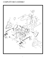
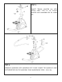
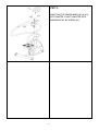
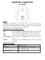
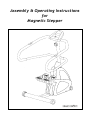
Assembly & Operating Instructions
for
Magnetic Stepper
1
COMPLETE BIKE ASSEMBLY
1
PARTS
NO
1
2
3
4
5
6
7
8
9
DESCRIPTION
Main Frame
Foot Tube
Stabilizer
Handlebar Post
Pulley I
Pulley II
Magnetic System
Bearing Housing
Belt I
10
11
12
13
14
15
16
17
18
19
20
21
22
23
24
25
26
27
28
29
30
31
32
33
34
35
36
37
38
39
40
41
42
LIST
Q’TY
1
2
1
1
1
1
1
2
1
NO
43
44
45
46
47
48
49
50
51
DESCRIPTION
Screw M12 x 85L
M12 Nylock nut
Screw M6 x 20L
Rubber stopper
Pedal
Washer 19 x 8
Screw M8 x 10L
Cap
Belt II
Bearing Hub
Spacerφ25 x 28 x 8.5L
Screw M8 x 45L
Washer 19 x 8 x 1.5T
M8 Nylock Nut
Axle
Key 6 x 6 x 15L
Screw M8 x 12L
Washer 12 x 16 x 1T
Nut 3/8 x 26t x 3T
Nut 3/8 x 26t
Springφ20 x 16 x 2 x 40L
Idle Wheel II
Nut 3/8 x 26t
Spring φ20 x 16 x 2 x 70L
Idle Wheel I
C Clip #19
Rubber stopper
C clip #13
M8 Nylock Nut
Moving wheel
1
2
8
8
8
1
1
1
1
1
4
2
1
1
2
1
1
4
2
4
2
2
52
53
54
55
56
57
58
59
60
61
62
63
64
65
66
67
68
69
70
71
72
73
O-Ring
Magnet
Tension adjuster
Screw φ8 x 33.5L
Screw M6 x 12L
Screw M8 x 10L
Washer 19 x 8
Handpulse sensor wire
Pulse sensor wire
Screw 4 x 12
Sensor wire I
Sensor wire II
Handlebar (R+L)
Screw 4 x 20
Handpulse sensor
Tension wire
Screw M5 x 40L
Screw M5 x 12L
Foam Grip
Meter
Top Cover
Screw M8 x 35L
Cap
Spacer φ19 x 12 x 60.5L
Chain
Chain-Spring connector
Spring
Spring connector
Screw M10 x 55L
M10 Nylock Nut
Spacer φ16 x 10 x 40L
Pedal fixing plate
2
2
4
2
2
2
2
2
2
2
2
74
75
76
77
78
79
80
Left Cover
Right Cover
Screw M5 x 12L
Screw 4 x 12
Screw 4 x 16
Screw 4 x 12
Rubber stopper
TOOL
Allen Key 6mm
Allen Key 5mm
Screw driver
2
Φ25 C Clip
Bushing φ76
Q’TY
4
4
8
2
2
4
4
2
2
4
1
1
8
8
4
4
2
1
1
1
1
2
2
2
1
1
4
2
1
1
1
1
1
2
2
3
4
2
1
2
1
ASSEMBLY INSTRUCTIONS
STEP 1.
ASSEMBLING THE STABILIZER (3) UNTO MAIN
FRAME BY SCREN (49) & WASHER (48).
STEP 2.
SLIDE THE TOP CORER (72) INTO HANDLEBAR
POST (4). CONNECT THE SENSOR WIRE (62) &
(63) TOGETHER. SLIDE HANDLEBAR POST ONTO
MAIN FRAME. FIXING THEM TOGETHER BY
SCRENS (57) & WASHERS (58) SLIDE TOP COVER
TO BOTTOM POSITION.
3
STEP 3.
CONNECT TENSION ADJUSTER (54) WITH
TENSION CABLE. THEN FIX THE TENSION
ADJUSTER ONTO HANDLEBAR POST BY SCREW
(68).
STEP 4.
ASSEMBLING HANDLEBAR ONTO HANDLEBAR POST. PLEASE CONNECT THE HANDPULSE CABLE
TOGETHER BEFORE JOIN THE HANDLEBAR. FIXING HANDLEBAR BY SCREW (55) & (56).
4
STEP 5.
CONNECTING THE SENSOR WIRES (60) & (63)
ONTO COMUTER. FIXING COMPUTER ONTO
HANDLEBAR POST BY SCREWS (69).
5
EXERCISE COMPUTER
BC-51007
NOTE
:
This monitor is equipped with an auto on/off function. The monitor will come on
automatically if the exercise machine is in motion. If stop exercising for over 4 minutes,
monitor will turn itself off & reset all functional data back to Zero. If start exercising again
within 4 minutes, monitor will accumulate all functional values.
FUNCTIONS AND OPERATIONS :
SCAN
Press the button until “SCAN” appears, monitor will automatically
cycles between STEP/MIN, TIME, COUNT, CALORIE every 4 seconds.
TIME
Press the button until “TIME” appears to count up the elapsed time.
COUNT
Press the button until “COUNT” appears to display the total repetitions.
STEP PER MINUTE Press the button until “STEP/MIN” appears to display the step per
minute.
CALORIE
Press the button until “CALORIE” appears to accumulate the calorie
consumption.
SPECIFICATIONS :
Sensor
Magnetic, Non-Contact
Power source
Requires two piece of 1.5V SIZE-AA or UM-3
Operating temperature
Storage temperature
0℃ - +40℃ (32℉ - 104℉)
-20℃ - +50℃ (-4℉ -122℉)
6