1
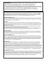
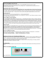
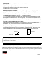
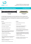
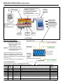
OPERATING INSTRUCTIONS MODEL PDXS25
FRONT PANEL:
PARALLEL OUTPUT
DB25F LPT CONNECTOR
GREEN LED - YELLOW LED
Left - Right Toggle Blinking Indicates
Normal Operation In Record Mode
● Waiting for Print Data
● Blinking pattern viewable at a distance.
NUL PRINTER
MODULE
REMOTE
ACCESS
MODULE
ETHERNET PORT
PORT SELECT SWITCH
FLASH MEMORY CARD
Press Eject
SERIAL PORT
PARALLEL
INPUT
9V DC
POWER JACK
POWER
LED
ILLUSTRATION #1
MODEL PDX-S FAMILY MODELS:
PDXS25-S: Uses Serial COMM type Access
Control Port to communicate to a
remote PC to control and retrieve
Flash Card print data.
No Ethernet feature is provided.
PDXS25-E: Uses rear panel switch to choose
an Access Control Port type: either
Serial COMM or Ethernet.
Model PDXS25 family does not stream data to the
capture PC in real time. It stores all data to a flash
memory card, independent of any PC. The user
accesses the card data with a PC at a time when desired.
No licence is used.
For real time streaming to a PC choose Model PT25.
RS232 SERIAL PORT
SETTINGS:
115.2K Baud
8 Data Bits
No Parity
Hardware Flow Control (RTS/CTS)
ILLUSTRATION #2
Controlling Model PDXS25:
No front panel controls are used. Control Model PDXS25 remotely.
Send simple ASCII commands to the Model PDXS25 Access Control Port
(RS232 Interface or Ethernet Connection).
ASCII
HEX
MODE
DESCRIPTION
RETURN
STRING BYTES
STRING
XS
58 53
PAUSE PLAY
PAUSES RETURN OF FLASH CARD DATA
XW
58 57
RECORD
APPENDS NEW DATA TO FLASH CARD
W
XE
58 45
ERASE CARD
REFORMAT FLASH CARD. RECORD.TXT SIZE = 0 BYTES
E*
XP
58 50
PLAY
PLAYBACK FLASH CARD DATA STARTING AT POINT ZERO
P (data)
XD
58 44
EFORMAT
EMERGENCY FORMAT SETS RECORD.TXT SIZE = 250MB
D*
XT
58 54
PASSTHRU
DISABLES RECORDING TO FLASH CARD, PASSES DATA TO PRINTER T
XL
58 4C
LENGTH
RETURNS APPROX. FILE SIZE OF FLASH CARD RECORD.TXT
FILE SIZE = n X
65K BYTES
XH
58 48
HARDRESET
PERFORMS A MASTER RESET OF MODEL PDXS25
TABLE # 1
H*
PAGE 1 OF 4
EXAMPLE OPERATION:
1. Connect printer cables only to Model PDXS25. See Illustration #1 above. Use NUL Printer Module to replace a printer.
2. Install Flash Memory Card (supplied). 512MB, 1GB, 2GB sizes. Always install Memory Card before powering up.
3. Power Up, and confirm Front Panel LEDs blink alternately: Green LED - Yellow LED, ( see Illustration #1 above).
Model PDXS25 is automatically in RECORDING Mode, and will record, without Remote Access Module serial or ethernet cable attached.
4. To control Model PDXS25, attach Remote Access Module serial or ethernet cable. Adjust port select switch for serial or ethernet operation.
5. If using serial port, see Illustration #2 above. If using ethernet port, see Lantronix XPort Direct + (TM) documentation.
6. Send Model PDXS25 Mode Commands, (see TABLE 1) eg. to retrieve Flash Memory Card data, and control Model PDXS25.
The user provides the remote software to communicate with the Model PDXS25.
INSTALLING FLASH MEMORY CARD:
Insert a new empty card or an existing card containing print data from a past recording (file: RECORD.TXT). If the card is new, the Model
PDXS25 will automatically format the card before it records, and create a RECORD.TXT file, with zero bytes. If the card is an existing card
with print data resident in the RECORD.TXT file, the Model PDXS25 will append new print data to it. After the card is inserted in Model
PDXS25, initiate the card by either: 1. powering up. 2. Issue a Hard Reset command from the remote capture PC.
REMOVING FLASH MEMORY CARD:
To unmount the flash memory card, set Model PDXS25 out of RECORD mode by using a remote command, or power down Model PDXS25
before removing card. When powering down, Model PDXS25 attempts to close the RECORD.TXT file automatically. Then it can be removed,
and read on a PC card reader, or a new card installed.
RECORDING:
Model PDXS25 will automatically enter RECORD mode when it is powered up. Confirm that LED's yellow and green alternately blink,
indicating a normal state waiting for print data, and ready to record. Print data that is recorded will append onto any existing print data from
previous flash memory card use. Cabling to a remote capture PC is not required. Recording can also be enabled/disabled by the remote
capture PC using mode commands.
Model PDXS25 does not alter the captured print data in any way. The raw print stream is stored on the flash memory card. The remote
system may apply any conversion or processing of the information to suit an exact need.
After approximately 250 MB has been recorded, further print data will print, but not be recorded. The remote PC user can obtain the flash
memory card file size status by issuing a file length query command to Model PDXS25: ASCII String "XL", see TABLE #1 above.
STOPPING RECORDING:
Use mode commands sent by the remote capture PC to control recording. Exiting RECORD closes the memory card file RECORD.TXT .
If Model PDXS25 is powered down, then the memory card RECORD.TXT file will be closed, and no data should be lost. When RECORD
mode is entered again, then new print data received will append to RECORD.TXT file.
READING FLASH MEMORY CARD:
Issue a PLAY command to the Access Control Port. The Model PDXS25 will return the contents of the flash Memory Card starting at the
beginning. The data is streamed out of the Model PDXS25 Access Control Port as if it was going to a printer. The PC must capture that data,
eg. Using MS Hyperterminal set to “Capture to File”. Many third party capture software programs are available. The user may design the
remote site software to control Model PDXS25 and and manage the data. The memory card may also be unmounted and read into a PC
using a memory card reader. The file is named RECORD.TXT
RECORD.TXT FILE:
This is the file name created on the flash memory card. It contains the raw print data received. It is 8 bits wide, which is then capable of
storing images and graphics. The data in the file is normally transferred to a remote capture computer using the Model PDXS25 Access
Control Module. The data can also be transfered to a PC by physically moving the card to a PC card reader or USB SD Card reader.
The card is dedicated to just one file named RECORD.TXT, and no other file is allowed on the card. The maximum file size is approximately
250Megabytes. When the card is returned to the ModelPDXS25, any new data recorded will append to the file. The RECORD.TXT file on the
memory card can be erased on a PC, or by Model PDXS25 using a Remote Access Module command issued by the remote control PC. The
RECORD.TXT is an exact image of the print stream, thus the file data would print to a similar printer for an exact copy of the original printout,
You may use DOS Prompt command if file is in PC folder, eg. C:\> COPY C:RECORD.TXT PRN
( copy file RECORD.TXT to printer).
VIEWING RECORD.TXT FILE DATA :
If the raw print data is not plain text, then a conversion viewing software must be applied to the RECORD.TXT file data, otherwise the data may
appear as garbage in a text viewer, eg. MS Notepad or Word. Many kinds of inexpensive third party software exists to convert for example,
PCL or Epson emulation raw print data to .pdf, .tiff , jpg. If the raw print data is simple plain text (eg. Generic Text) , then the print data is
basically readable in simple wordprocessor applications, such as MS Notepad, or Word, or perhaps Excel and other spreadsheets. The user
may perform formating and parsing of data using a programming language, eg. Visual Basic to suit an exact application.
PAGE 2 OF 4
ERASING FLASH MEMORY CARD PRINT DATA:
Issue an erase command from the remote capture computer. This will set RECORD.TXT file size on the card to 0 bytes.
The flash memory card may also be erased manually on a PC by deleting all files. The Model PDXS25 will automatically create a new
RECORD.TXT with file size = 0 bytes.
PRINTING WHILE MODEL PDXS25 IN PLAY MODE:
If the users main system issues a print job while the Model PDXS25 is PLAY mode (transmitting memory card data to the remote system), then
the main system will see it as a busy printer, and no print data should be lost. The busy would be similar to a printer busy state if it was offline
or out of paper. When the PLAY mode is ended, and RECORD is entered, then the main system sees a not busy state, and Model PDXS25
can resume recording where it left off. This busy action is used for any other operating mode of Model PDXS25 to prevent loss of data.
SETTING BAUD RATE:
Baud rate is factory fixed to: 9600 Baud (Model PDXS25-S) or 115.2K Baud (Model PDXS25-E).
Approximate thoughput is 960 chars/sec for 9600 Baud, and 11,500 chars/sec for 115K Baud. Note: The Ethernet connection is currently
limited to approximately 11K characters/sec.
SETUP OF REMOTE CAPTURE COMPUTER:
The user must implement capture software on the capture computer. Choose RS232 Serial COM Port or Ethernet connection, depending on
the model of PDXS25. This may be as simple as Windows Hyperterminal capture software for COM Port connection. For Ethernet connection,
use Lantronix XPort Direct + (TM) documentation, as Lantronix hardware device server is embedded inside Model PDXS25-E. Issue Access
Control Commands to set the modes of Model PDXS25. When using ethernet connection, it is still possible to use Windows Hyperterminal, as
Lantronix COM Port ReDirector software will make the TCP/IP link look like a serial com port for Hyperterminal. When the capture is complete,
and is saved in a folder, then various viewing conversion software may be applied to the file as necessary to suit the users exact need.
POWER FAILURES:
If a power outage occurs, the model PDXS25 detects it, and is normally able to close the flash memory card recoding file RECORD.TXT When
power returns, Model PDX automatically starts up in RECORD mode, and appends new data to RECORD.TXT No data should be lost in
Model PDXS25 flash memory if a power outage and power return occurs, however certain unusual power failures may cause failure of
RECORD.TXT to close. Normally there should be no operator intervention required for Model PDXS25 when power returns. It is assumed that
a printer in the system also recovers on it's own by going ONLINE automatically when powered up.
SCOPE OF 250 MEGABYTE FILE SIZE:
Example number of Generic Print text print linesthat may be stored: 250,000,000 byte capacity/ 136 characters/line = 1.8 million lines
Time to retreive 1 MB using 9600 Baud:
1,000,000 / 960 Characters/second = 1,041 seconds
Time to retreive 1 MB using 115.2K Baud: 1,000,000 / 11,520 Characters/second = 87 seconds
EMERGENCY RECOVERY OF DATA STRANDED ON THE MEMORY CARD:
If for some reason the card becomes corrupt and RECORD.TXT cannot be read, a procedure to reformat the card with 250MB file size can be
performed. This effect may make it possible to access the whole memory card capacity just by opening the RECORD.TXT in a Windows
system. The data however may be organized in random groups with past file contents.
Procedure: With memory card installed, press Red Pushbutton inside Model PDXS25 unit while powering up. The memory card will be
formated to contain RECORD.TXT with file size = 250 MB
PRINTER SECURITY:
The remote access capture computer can only receive print data. The remote access capture computer cannot send any print data to the
printer.
REMOTE ACCESS MODULE CONNECTORS:
Shown: Model PDXS25-E
PAGE 3 OF 4
PROBLEM SOLVING:
Cannot record because front panel LED's Yellow and Green do not alternately blink:
The Model PDXS25 is not ready for recording:
1. The flash memory card may be unsuitable, or missing.
3. The remote capture computer has issued a command to stop recording.
4. The remote capture computer must use uppercase ASCII characters in the command strings.
5. The Model PDXS25 may require a power up reset.
What happens if the remote PC is non-functional:
1. Model PDXS25 continues to record without a PC as long as it is in RECORD mode. To manually set Model PDXS25 in RECORD mode,
power up PDXS25. The distinct alternate blinking of the Green & Yellow front panel LEDs confirms the unit is in RECORD mode.
2. To collect the flash card data without using a capture PC communications link, manually carry the flash card to a PC with a card reader, or
USB card reader. Power down before removing the memory card from Model PDXS25.
The captured data looks like garbage on a PC: an example: " sP╧H Áĕ!wR#RRRΛĆĆÁÁÁke4%R "
1. If the users printer cable is not transmitting Generic Text data, then the data may contain formating codes, escape sequences, font loads,
and even graphics that use byte values ranging from 00Hex to FF Hex (256 range). Check that a repeat of the print job displays exactly the
same garbage character sequences, then that indicates it is not random garbage, but data that requires conversion using software.
2. If the print job is repeated several times, and the garbage pattern is not identical, then possibly the communication link is not setup correctly.
eg, Baud rate mismatch, or Hardware Flow Control missing.
Cannot obtain any response from Model PDXS25 at remote capture site:
If Model PDXS25 was stalled due to some operator event, it may be re-powered up from the remote site using HARD RESET Command. An
acknowledge code: " H* " string will be returned to the remote site to indicate re-established communication.
At installation, no recording can ever be made:
This may be caused by Model PDX-S inability to communicate with the users main system computer printer cable. The printer interface may
not be ASCII type. It may be GDI interface (WinPrinter proprietary type interface), or engine type Non-ASCII bidirectional raster interface.
Check the printer manual for parallel interface type. Use IEEE-1284 Centronics, or classic Centronics Parallel. Model PDXS25 is generally
compatible to all parallel interfaces on legacy systems, Windows DOS, instruments/machines, and print servers. Setup a test Test
PC
SETUP TO TEST FUNCTIONALITY:
MODEL PDXS25
STRAIGHT THRU SERIAL CABLE
COM
PORT
OPEN WINDOWS
HYPERTERMINAL™
TO SEND / RECEIVE DATA
PDXS25RUN.PDF
PARALLEL CABLE
REFERENCE DOCUMENTATION:
Photologic Ltd. PDXS25.PDF Model PDXS25 Description, Specifications, and Control Commands List
Lantronix XPort Direct + ™ Users Guide: http://www.lantronix.com/pdf/XPort-Direct-Plus_UG.pdf
Lantronix XPort Direct + ™ Quick Start Guide
Disclaimer This information is subject to change without notice. Please check with a Photologic Ltd. sales representative for availability and additional information.
Photologic Ltd. assumes no responsibility for any errors that may appear in this document. No license, express, implied or otherwise, is granted under any patents,
copyrights or other intellectual property rights of Photologic Ltd. or others. Descriptions of product device, software and other related information in this document are
provided for illustrative purposes in product operation and application examples. The incorporation of this information in the design of customer's system shall be done
under the full responsibility of customer. Photologic Ltd. bears no responsibility for any losses incurred by customers or third parties arising from the use of this product
and information. While Photologic Ltd. endeavors to enhance the quality, and reliability of this product, customers agree and acknowledge that the possibility of defects
thereof cannot be eliminated entirely.
PHOTOLOGIC LTD. FEDERAL BUILDING • 39 QUEEN STREET, SUITE 214 • COBOURG, ONTARIO • CANADA K9A 1M8
PAGE 4 OF 4