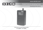
1
210-1000 Series
Operating Instructions
SKC Inc.
863 Valley View Road
Eighty Four, PA 15330 USA
Form #37717 - Rev 0605
Table of Contents
Description ................................................................................................... 1
Performance Profile ..................................................................................... 2
Introduction .................................................................................................. 4
Interpreting Pump Operating Terms ................................................................................................ 4
Interpreting LCD .............................................................................................................................. 4
Operation ..................................................................................................... 5
Operating the Keypad ...................................................................................................................... 5
Determining Pump Operating States ............................................................................................... 6
How to Set up Pump ....................................................................................................................... 7
Calibrating/Setting for Constant Flow Applications ........................................................................ 10
Setting for Multiple Tube Sampling Using Constant Flow Mode .................................................... 12
Setting for Multiple Tube Sampling Using Constant Pressure Mode .............................................. 14
Pump Care and Maintenance .................................................................... 17
Battery Care and Maintenance .................................................................. 18
Replacing Battery Pack .................................................................................................................
Battery Pack Charging System ......................................................................................................
Charging Battery Pack ...................................................................................................................
Discharging Battery Pack ..............................................................................................................
Continuous Operation Using Charger ............................................................................................
Battery Notes .................................................................................................................................
Technical Note ..............................................................................................................................
18
20
21
22
22
23
24
Service Policy ............................................................................................ 25
Accessories ............................................................................................... 26
DataTrac Software ........................................................................................................................ 26
Optional Accessories ..................................................................................................................... 28
Warranty ..................................................................................................... 29
UL Certificate ................................................................................................................................. 30
Index ........................................................................................................... 31
Indicates a caution or warning.
Indicates a reminder.
These Pocket Pump Operating Instructions are also available in
Spanish and French Canadian. Visit www.skcinc.com.
Notice: This operating instruction may not address all safety concerns (if any) associated with this product and its use.
The user is responsible for determining and following the appropriate safety and health practices and regulatory
limitations (if any) before using the product. The information contained in this document should not be construed as
legal advice, opinion, or as a final authority on legal or regulatory procedures.
Description
Your new SKC Pocket Pump is an advanced low flow sample pump combining lightweight and compact design with computer-compatible circuitry. When used with SKC
sampling media such as sorbent sample tubes, the Pocket Pump is efficient and accurate for performing TWA, STEL, and Ceiling sampling for organic gases and vapors.
The result of extensive research and development, the Pocket Pump exemplifies SKC's
commitment to quality and innovation in industrial hygiene sampling equipment.
Flow Rate: 20 to 225 ml/min
1
Performance Profile
Flow range in constant
flow mode:
20 to 225 mL/min
Accuracy variance between
LCD reading and actual flow
rate (after calibration):
20 to 225 mL/min + 5%
Constant flow compensation:
+
Pressure range in constant
pressure (multiple tube
sampling) mode:
1 to 10 inches water (1.87 to 18.7 mm Hg) at
maximum flow rate of 200 mL/min for 8 hrs (12
hrs if using NiMH battery).
10 to 20 inches water (18.7 to 37.4 mm Hg) at
maximum flow rate of 100 mL/min for 8 hrs (12
hrs if using NiMH battery).
5% of flow reading up to 20 inches water
Constant pressure (multiple
tube sampling) mode accuracy:
Pressure reading + 0.5 inches water (0.25 mm Hg)
Battery charge level indicator:
Icon displays at full, mid, and low charge
Temperature range:
Operating:
Charging:
20 to 110 F (-7 to 43 C)
40 to 100 F (5 to 38 C)
Protect sample pump from weather when in use outdoors.
Total varies with flow rate and sampling media
in line. At 200 mL/min, 10 inches water back
pressure, nominal run time is approx. 8 hrs. At
200 mL/min and 20 inches water back pressure,
nominal run time is approx. 6 hrs. Connected to
a charger, run time is indefinite.
Run time:
If using a Nickel Metal Hydride battery, run
times are increased to up to 12 hrs in most
sampling situations.
• RFI/EMI shielded
• CE approved
c
• UL and cUL listed.
• ATEX-approved model 210-1002
See UL Certificate on page 30.
2
Note: If using a Nickel Metal
Hydride (NiMH) battery pack,
run times are extended to up to
12 hours in most sampling
situations.
Performance Profile
Timer:
1 to 9999 min display +1% accuracy
Flow fault:
Pump stops and holds historical data when flow
is restricted. Auto-restart attempted every 5 min.
Battery pack:
Built-in battery pack
Rechargeable NiCad 2.4 V x 0.6 Ah or
Nickel Metal Hydride (NiMH) 2.4 V x 1.0 Ah. See
Battery Notes and Technical Note on pages 23 and 24.
Size:
4.5 x 2.2 x 1.4 inches (11.4 x 5.6 x 3.6 cm)
Weight:
5 ounces (142 gm)
The use of a repaired or rebuilt battery pack voids the SKC warranty
and the UL Intrinsic Safety Listing
2.2”
Note: Newer pump models contain an NiMH
battery. An NiMH battery can be used with older
Pocket Pump models. Simply order Replacement Part
No. P20129-2 NiMH Battery Pack.
4.5”
Note: SKC designs its pumps to minimize inherent
noise. If the noise level is disturbing when the
Pocket Pump is worn in a shirt pocket, SKC
recommends clipping the pump on a waist belt.
3
1.4”
Introduction
Interpreting Pump Operating Terms
In this manual, “run time data” refers to all the terms listed below:
FLOW:
Flow rate in milliliters per minute (mL/min).
VOLUME: Total volume of air in milliliters (mL) or liters (L) since reset.
PRESSURE: Pump back pressure measured in inches (ins) of water or millimeters (mm)
Hg.
TEMP:
Temperature of incoming air in C or F.
RUN TIME: Time in minutes (min) since reset.
FAIL:
A type of fault indicating insufficient battery capacity (see p. 21 ).
Interpreting the LCD
Operating Indicators
PROG:
HOLD:
ADJ:
FLOW:
VOL:
SET:
Active when a program is loaded into the Pocket Pump memory by
DataTrac® software.
Active when the Pocket Pump is in the HOLD state.
Active when the Pocket Pump is being flow calibrated.
Active when the LCD shows the flow rate.
Active when the LCD shows the volume of air pumped.
Flashes when setting the flow rate of the Pocket Pump.
Icons
Flow Fault: Flashes during flow fault
Battery:
Shows battery condition
Display Units
˚C
˚F
ins
mm
mL/min
min
Degrees Celsius. Active when the LCD shows temperature in Celsius
scale.
Degrees Fahrenheit. Active when the LCD shows temperature in Fahrenheit scale.
Inches. Active when the LCD shows the back pressure in inches water.
Millimeters. Active when the LCD shows the back pressure in millimeters
Hg.
Milliliters per minute. Active when the LCD shows the flow rate.
Minutes. Active when the LCD shows run time.
Operating indicators
Flow Fault Icon
Flow fault
PROG HOLD ADJ FLOW VOL SET
Battery
charge
status
°C °F ins
Numerals
mmL/min
Battery Icon
Display units
4
Operation
Operating the Keypad
The Pocket Pump operates by pressing
various sequences of the three keypad
buttons located beneath the sliding cover.
Operate the Pocket Pump with the following key sequences:
Pocket Pump Keypad
Star Button ✹
• Scrolls through running data displayed on the LCD.
• Sets up the pump operation when used with other buttons.
Up and Down Arrow Buttons ▲ ▼
• Increases or decreases either flow (constant flow mode) or pressure
(constant pressure mode) during the setup.
Underlined Sequence ✹▲▼✹
• All buttons in that sequence must be pressed within 10 seconds of previous
command.
Bracketed Sequence [ ▲▼ ]
• All buttons within brackets must be pressed simultaneously.
Security Code ✹▲▼✹
• Pocket Pump operating parameters cannot be changed without pressing the
security code sequence.
• The security code may be required at various points during programming.
In this manual, button
sequences are shown in the
order in which the buttons
should be pressed.
Pressing both the up and down
arrow buttons simultaneously
places a running pump in
HOLD or a holding pump in
RUN.
5
Operation
Determining Pump Operating States
If the LCD shows:
RUN
• The pump is running and run time data is updated continuously in memory.
HOLD
• The pump is off and run time data is stored.
• Temperature and back pressure readings are still active and shown on the
LCD.
FLOW FAULT (
)
• The pump operation is interrupted due to blocked or restricted flow.
• The flow fault icon will flash and the pump goes into HOLD mode (flow
fault icon is steady and HOLD flashes on LCD).
• The pump will restart operation in five minutes and try to continue sampling.
• If flow remains restricted, the pump goes back to HOLD mode (HOLD flashes
on LCD) and attempts to restart every five minutes or until the restricted
flow is corrected.
SLEEP
• The LCD shuts down and the electronic circuitry enters a low power state.
The pump automatically enters SLEEP mode after five minutes in HOLD
unless the battery charger is plugged in or a keypad button is pressed.
FAIL
• A fault state in which the battery capacity is insufficient to run the pump
motor (see FAIL Display on p. 21).
To change the pump from HOLD to
RUN press [▲▼]
Flow Fault Indicator
To change the pump from RUN to
HOLD press [▲▼]
The time the pump is running in
Flow Fault mode is not added
to the displayed run time or
cumulative volume display.
To change the pump from SLEEP to
HOLD press any button
6
Operation
How to Set Up the Pocket Pump
To activate the pump:
• Press any keypad button. The LCD will show the pump’s serial number for
two seconds followed by an internal software revision number.
To determine the battery charge:
• The pump will operate for approximately eight hours with a NiCad battery
and up to 12 hours with an NiMH battery at a flow rate of 200 mL/min and
back pressure of 10 inches of water. Pump operation time will increase as
flow rate and back pressure rates are decreased.
• The LCD shows the current battery charge level. The icons appear as follows:
Three bars indicate a full charge and appear for approximately the first two
hours of operation. If using an NiMH battery, this appears for approximately
the first three hours of operation.
Two bars indicate main running time and display for approximately five hours.
If using an NiMH battery, this indicates approximately eight hours.
One bar indicates that there is approximately one hour of run time remaining.
If using an NiMH battery, this indicates approximately one hour of run time
remaining.
When all bars are clear and the outline is flashing, the pump goes into HOLD
mode, then to SLEEP mode in approximately one minute.
Pump run time is a converse relationship:
Low flow+Bp=longer run time
High flow+Bp=shorter run time
Note:
7
Operation
To obtain run time data:
• Press the ✹ button. After displaying the data, the pump will return to SLEEP
mode in ten seconds. This sequence can be repeated.
To reset the data display to zero:
• With the pump running, press:
[▲▼] (HOLD) ✹▲▼✹ (Security Code) ✹✹
The LCD will briefly show the pump serial number, software version number, and run time at 0 min. This will clear all data except the flow setting. See
instructions on page 10 to change the flow setting.
To determine the pump operating mode (Constant flow or
Constant pressure)
• Look at the LCD. Use the ✹ button to scroll through the displays if necessary.
Multiple tube (constant pressure) mode
Constant flow mode
FLOW
.
ins
mL/min
1 to 3 digit number is displayed
with “P”, and an “ins” or “min”
1 to 3 digit number is displayed
with “mL/min” and “FLOW”
Enhanced Display
scrolls through
flow, volume, back pressure,
temperature, and run time
Standard Display
scrolls through flow, volume, and
run time
To change the operating mode (Constant flow or Constant
pressure)
• With the pump running, press:
[▲▼] ( HOLD) ✹▲▼✹ (Security Code) ✹▼▲✹
The display will now show the new operating mode as indicated above.
Note: If you do not want to clear the run time data after entering the security code,
stop and wait 10 seconds to break the sequence. The LCD will stop flashing at this
point.
8
Operation
To select pump display:
• Standard to Enhanced Display:
With pump running, press:
[▲▼] (HOLD) ✹▲▼✹ (Security Code) ✹▲▲✹
The enhanced data display will scroll through FLOW, VOLUME, BACK
PRESSURE, TEMPERATURE, and RUN TIME.
•
Enhanced to Standard Display:
With pump running, press:
[▲▼] (HOLD) ✹▲▼✹ (Security Code) ✹▼▼✹
The standard data display will scroll through FLOW, VOLUME, and RUN
TIME.
To select the temperature scale display:
• In enhanced display, the temperature of incoming air can be shown in either
Celsius (C) or Fahrenheit (F) scale. Use the ✹ button to scroll to the temperature scale display units.
To change temperature from Celsius (C) to Fahrenheit (F) or
Fahrenheit (F) to Celsius (C):
• With pump running, press:
[▲▼] (HOLD) ✹▲▼✹ (Security Code) [✹▼ ]
The display will show the selected temperature scale.
To select pressure units:
• In enhanced display, back pressure can be shown in either inches (ins) of
water or millimeters (mm) of Mercury. Use the ✹ button to scroll to the back
pressure display units.
To change back pressure units Inches (ins) to Millimeters of
Mercury (mm) or Millimeters of Mercury (mm) to Inches (ins):
• With pump running, press:
[▲▼] (HOLD) ✹▲▼✹ (Security Code) [▲✹ ]
The display will show the selected pressure unit.
When you see a keypad button sequence that is underlined in this manual,
press the buttons in that sequence within 10 seconds of the previous command.
If a bracketed sequence appears, press the keypad buttons in the brackets
simultaneously.
9
Operation
Calibrating/Setting the Pump for Constant Flow
Applications
For single sorbent tube and long-duration detector tube sampling:
1. Set the pump for Constant Flow mode (see page 8).
2. Connect the pump to either a representative sorbent tube using an SKC tube holder
or a long-duration color detector tube using an SKC tandem tube holder and trap
tube.
Long-duration Color Detector Tubes require a special tube cover that
accommodates an in-line trap tube. The trap tube protects the pump from
caustic fumes that are often released from detector tubes. Closely read
all precautions when using these tubes. Failure to use the necessary traps
will damage the pump and void the warranty.
3. Connect the exposed end of the tube to a primary
standard calibrator using another length of tubing.
Low flow tube holder
Sample tube
5. Enter the security code ✹▲▼✹ within ten seconds. The word SET will flash on the LCD.
Sample tube cover
SKC
4. Press [▲▼] for RUN mode.
Tygon tubing
6. The LCD will display the flow rate set from the
last sample taken. If you do not wish to change
the flow rate, go to step 8.
FLOW
mL/min
Air Flow
7. Press ▲ or ▼ to change the flow rate to the desired setting.
When calibrating the pump, the flow rate displayed on the calibrator will
change as a result of adjusting the pump flow rate. The actual pump flow rate
(not the display) and the calibrator must ultimately agree.
10
Operation
8.
Press ✹. The word ADJ appears on the LCD. The pump flow rate can now be
calibrated using a calibrator.
9.
When the flow rate reading appears on the calibrator, press the ▲ or ▼ buttons
on the pump keypad to adjust the flow up or down until the pump and calibrator
agree. The flow rate displayed on the calibrator will change as a result of adjusting the pump flow rate. The actual pump flow rate (not the display) and the
calibrator must ultimately agree.
10. Press ✹ to lock in the calibrated flow. The pump will then enter its normal RUN
state.
11. Press [▲▼] to place the pump in HOLD. Enter [▲▼] ✹▲▼✹ (Security Code)
✹✹ to clear data (minutes that have elapsed during pump setup and/or programming) before sampling.
12. Disconnect the calibration system and replace the representative sample tube
with the tube to be used for sampling.
13. Clip sampling medium to a worker’s collar in the breathing zone and place the
Pocket Pump in the worker’s shirt pocket or clip to the worker’s belt.
14. Press [▲▼] to RUN the pump and begin sampling.
15. Press [▲▼] to HOLD the pump and stop sampling. Pump data is retained in
memory after sampling is completed. While the pump is in the HOLD mode,
use the ✹ button to scroll through the data on the LCD.
Protect sample pump from weather when in use outdoors.
Note:
SKC designs its pumps to minimize inherent noise. If the noise level is
disturbing when the Pocket Pump is worn in a shirt pocket, SKC recommends clipping the pump on a waist belt.
11
Operation
Setting the Pump for Multiple Tube Sampling Using
Constant Flow Mode
For use with constant pressure controller and multi-port
adjustable low flow tube holders:
The Constant Pressure Controller (CPC) (Cat. No. 224-26CPC-10) is a Pocket Pump
accessory that provides a simple alternative for multiple sorbent tube sampling while
in Constant Flow mode. In conjunction with an Adjustable Low Flow Tube Holder
(Catalog No. 224-26-02, 224-26-03, or 224-26-04), the CPC is used as a pressure
regulator to maintain a constant 10 inches water back pressure.
For multi-tube sampling:
1.
Set the pump for Constant Flow mode (see page 8) and set it to the selected flow
rate (see page 10-11, steps 4 through 11). The flow rate of the Pocket Pump
must be greater than the sum of the flow rates through the tubes. The sum of the
flow rates cannot exceed 200 ml/min to achieve an 8-hour run time (12-hour
with NiMH battery).
Example using two tubes:
Tube
Port
Flow (mL/min)
1
A
50
2
B
40
50 + 40 = 90. Therefore the flow rate of the Pocket Pump must be greater than 90.
2.
Connect the pump inlet to the CPC outlet (the side of the CPC without a label)
with a 1/2- to 1-inch length of Tygon®
tubing.
3.
Connect the inlet side of the CPC
(marked “to sample”) to the Adjustable
Low Flow Holder.
CPC
Tube Holders
Flow
Adjustment
Screws
Inlet
FLOW
mL/min
Sample Tubes
Sample Pump
Note:
When multi-tube sampling, the flow rate of the Pocket Pump must be greater
than the sum of the flow rates through the tubes. When using the CPC, the
sum of the flow rates cannot exceed 200 mL/min to achieve an 8-hour run time
with a NiCad battery or a 12-hour run time with an NiMH battery.
Note:
When performing multiple tube sampling, the volume display on the LCD is
the sum of the volumes drawn through all the tubes.
12
Operation
4.
Label all tubes and ports (e.g., Tube #1, port A).
5.
Insert the first opened representative tube (#1) into the first port (A), etc. Place
unopened tubes in any unused ports to “seal” them. This is essential to obtain
correct results.
6.
Connect the exposed end of one tube to a primary standard calibrator using
another length of tubing.
7.
Press [▲▼] to RUN the pump.
8.
Turn the flow adjustment screw (needle valve) on the adjustable tube holder
until the calibrator matches the selected flow rate through the tube. Note: the
flow rate displayed on the calibrator changes as a result of this adjustment.
9.
To calibrate each tube’s flow rate, repeat steps 6 through 8 for each port.
10. Press the [▲▼] to place the pump in HOLD mode. Enter [▲▼] ✹▲▼✹
(Security Code) ✹✹ to reset the data display before sampling.
11. Disconnect the calibration system and replace the representative sample tubes
with the tubes to be used for sampling. The pump is ready to run.
12. Clip sampling medium to a worker’s collar in the breathing zone and place the
Pocket Pump in the worker’s shirt pocket or clip to the worker’s belt.
13. Press [▲▼] to RUN the pump and begin sampling.
14. Press [▲▼] to HOLD the pump and stop sampling.
Pump data is retained in memory after sampling is completed. While the pump is in
the HOLD mode, use the ✹ button to scroll through the data on the LCD.
Pressing [▲▼] will place a running pump in HOLD, and a holding pump in
RUN.
Note:
Protect sample pump from weather when in use outdoors.
All empty ports must contain unopened tubes during calibration.
13
Operation
Setting the Pump for Multiple Tube Sampling Using
Constant Pressure Mode
(For use with multi-port adjustable low flow tube holder)
1.
Enter enhanced display and Constant Flow mode (see page 8). Remain in these
modes until ready to calibrate.
2.
Connect the pump to an Adjustable Low Flow Tube Holder (see Optional Accessories, page 28). Use a screwdriver to turn all of the set screws counterclockwise until they are flush with the tube holder surface.
3.
Label all tubes and ports (e.g., tube #1, port A).
4.
Insert the first opened representative tube (#1) into the first port ("A"), etc. Place
unopened tubes in any unused ports to “seal” them. This is essential to obtain
correct results.
5.
Set the desired flow rate (see page 10-11, steps 4 through 11) as specified by the
method for tube #1 in port (A). Record the flow rate.
6.
Press the ✹ button to scroll to Constant Pressure mode (in H2O or mm Hg).
While the pump is in RUN, record the back pressure for that tube. Press [▲▼]
to place pump in HOLD.
7.
Repeat steps 4 through 6 for each port to obtain each tube's back pressure.
All empty ports must contain unopened tubes during calibration.
When performing multiple tube sampling in Constant Pressure mode, the flow
rate must be set as low as possible. The sum of the flow rates cannot exceed
100 mL/min for back pressures from 10 to 20 inches of water; the sum of the
flow rates cannot exceed 200 mL/min for calculated back pressures less than
10 inches of water.
14
Operation
8.
Obtain the calculated back pressure by adding 1 inch to the highest back pressure number and rounding up to the next number. The additional inch allows for
typical back pressure fluctuations.
Example using two tubes:
Tube
1
2
Port
A
B
Flow
(mL/min)
20
50
Back Pressure
(in H2O)
6.2
7.9
Calculated back pressure is 9 (7.9 +1 = 8.9 rounded to 9).
9.
Insert opened representative tube (#1) back into port (A). Place unopened tubes
in remaining port(s) to “seal” them.
10. Reset the pump to the desired flow rate for port (A) as done in step 5.
11. Press ✹ to scroll to Constant Pressure mode (ins or mm). While the pump is still
in RUN, use a screwdriver to turn the set screw clockwise for port (A) on the
Adjustable Low Flow Tube Holder until it matches the calculated back pressure. Press [▲▼] to place the pump in HOLD.
12. Repeat steps 9 through 11 for remaining port(s).
13. Place pump in Multiple Tube (Constant Pressure) mode by pressing [▲▼]
(HOLD) ✹▲▼✹ (Security Code) ✹▼▲✹ .
Pressing [▲▼] will place a running pump in HOLD, and a holding pump in
RUN.
15
Operation
14. Set pump pressure to the calculated back pressure. From HOLD, press [▲▼] to
RUN the pump, then enter the ✹▲▼✹ (Security Code) within ten seconds. The
LCD will display the previously set back pressure, with flashing SET and P
indicators. The flow fault icon may also be flashing at this point.
15. Press ▲ or ▼ to increase or decrease the previously set back pressure setting
until it matches the calculated back pressure determined in step 8. Press ✹ to
lock in the pressure setting. The pump will then return to its normal RUN state.
16. Clear data (minutes that have elapsed during pump setup and/or programming)
before sampling by pressing [▲▼] (HOLD) ✹▲▼✹ (Security Code) ✹✹.
17. Remove the tubes used for calibration and insert new opened representative
tube(s) in their assigned port(s). The pump is now ready to run.
18. Press [▲▼] to RUN the pump and begin sampling.
19. Press [▲▼] to HOLD the pump and stop sampling.
Pump data is retained in memory after sampling is completed. While the pump is in
the HOLD mode, use the ✹ button to scroll through the data on the LCD.
When performing multiple tube sampling in Constant Pressure mode, the flow
rate must be set as low as possible. The sum of the flow rates cannot exceed
100 mL/min for back pressures from 10 to 20 inches of water; the sum of the
flow rates cannot exceed 200 mL/min for calculated back pressures less than
10 inches of water.
Protect sample pump from weather when in use outdoors.
16
Pump Care and Maintenance
The Pocket Pump has been carefully designed, manufactured, and tested to give excellent performance. Proper care and maintenance include:
• Avoiding dropping the pump or subjecting it to strong impacts.
• Keeping the pump dry.
• Not cleaning the pump with harsh cleaning solvents or detergents.
• Storing the pump in a cool, dry, dust-free location.
• Following instructions in the Battery Care and Maintenance section to
maximize battery life.
When using the charger, the battery icon displays as a solid outline with three
flashing bars (during "fast-charge"). It will then go to a solid outline with three
solid bars (during "trickle-charge").
When the battery loses all of its charge, the battery icon displays as a flashing
outline with no bars.
17
Battery Care and Maintenance
Replacing the Battery Pack
FLOW
mL/min
1. Press down on the sliding keypad cover near the SKC logo with
your thumb, and push the keypad cover down and away from the
display until it is free from the pump.
▲
✳
mL/min
FLOW
▲
✳
▲
▲
2. Lay the pump on a flat surface with the LCD
facing upwards. Remove the two screws on the
front panel of the pump.
3. Turn the pump over so that the LCD faces down. Remove the
belt clip by unscrewing the single locking screw, and remove
the battery compartment cover.
The use of a repaired or rebuilt battery pack voids the SKC warranty and the
UL Intrinsic Safety Listing.
18
Battery Care and Maintenance
4. Unplug the old battery pack by carefully lifting it upwards,
and remove it from the pump.
5. Plug in the replacement battery pack. Replace the
battery compartment cover and belt clip.
▲
▲
✳
min
6. Turn the pump over so that the LCD faces upwards. Replace the two screws on the front panel
of the pump (do not overtighten the screws) and
replace the keypad cover.
min
7. Charge the new battery pack (see page 21).
Do not charge or operate the pump with the charger in hazardous atmospheres!
Use only SKC-approved charger and battery pack designated for the Pocket
Pump to ensure reliable performance and intrinsic safety and to maintain the
SKC warranty.
19
Battery Care and Maintenance
Battery Pack Charging System
The SKC Pocket Pump features the innovative "Smart Charging Battery System." The
advanced technology of the battery pack's circuitry provides multiple features:
• It allows the battery pack to regulate the charge it receives by reducing its fast
charge rate to a trickle charge rate when the battery is at maximum capacity
thus preventing damage to the battery.
• It is also designed to prevent harm to the battery by charging only if the battery is within its acceptable charging temperature range of 40 to 100 F (5 to 38
C). Outside of this range, the battery will only accept the low output trickle
charge.
20
Battery Care and Maintenance
Charging the Battery Pack
To charge the battery, plug the charger into a standard wall outlet and the charging
jack into the battery port on the back of the pump. The fast charging function of the
battery pack will completely recharge the battery in approximately 6 hours or less
when battery pack is attached to the pump. The Pocket Pump battery can be charged
detached from the pump, however, it will only accept a slow charge and will charge
in approximately 16 hours.
◆ During “fast-charging,” the battery icon displays a solid outline with three
flashing bars.
◆ During “trickle-charge” and upon receiving a full charge, the battery icon
is a solid outline with three solid bars.
◆ When the top bar is flashing and the bottom two bars are solid, a
charging fault has occurred. A charging fault may be caused by:
• Changing ambient temperatures
• A defective battery pack
• A disrupted charge cycle
To remove a charging fault, unplug the charger, allow the pump to equilibrate
to the ambient temperature, and retry. If the icon display persists, call SKC
at 724-941-9701.
FAIL Display
Symptom: Press [▲▼] from Hold mode to Run the pump. Pump will not run and
immediately goes back to Hold mode.
Display: Press ✹ to scroll through display until FAIL appears.
Explanation: FAIL is a type of fault caused by battery capacity that is insufficient
to start the pump motor. This indicates a battery pack that has either developed a
fault or is at the end of its life. The fault cannot be fixed by recharging the failing
battery pack.
Solution:Remove the battery pack and replace with a new, fully charged battery
pack. Run the pump and scroll through the display. If the pump runs and FAIL is
not displayed the fault is fixed. If FAIL still displays, there is a fault in the pump
electronics. Send pump to SKC for repair.
Unplug the charging jack from the
Pocket Pump battery port when
finished charging the battery pack.
If the charger is unplugged from a
wall outlet and the charging jack is
left in place, the battery charge will
deplete.
Use only SKC-approved batteries
and charger to ensure reliable
performance and intrinsic safety.
Using a non-approved charger
voids the SKC warranty and could
damage the pump or battery.
Ensure that the computer interface
port is covered before and during
charging.
Do not charge in hazardous
environments.
21
Battery Care and Maintenance
Discharging Battery Packs
“Memory effect” is a characteristic of Nickel-Cadmium (NiCad) batteries that prevents the batteries from being fully recharged. To eliminate “memory effect,” maximize battery life, and provide optimum performance, completely discharge NiCad
batteries after every 40 hours of operation or every 30 days or use a charging system
that does not promote memory effect. Nickel Metal Hydride (NiMH) batteries are
not likely to develop “memory effect.” Use a charging system that does not promote
memory effect for optimum performance.
To discharge the battery pack completely:
1. Enter the Constant Flow mode (see page 8).
2. Set the Pocket Pump flow rate to a flow of 225 mL/min (see pages 10-11, steps 4
through 11).
3. Allow the pump to run until the battery charge is exhausted.
4. Recharge the battery (see page 21).
Continuous Operation Using Charger
Continuous pump operation is possible in nonhazardous environments using the
pump with battery charger plugged into a wall outlet.
It is important to note that the battery will discharge during a continuous run operation, however, when its charge drops by 50%, the fast charge feature is initiated until
the battery receives a full charge. This cycle repeats every several hours during the
operation.
22
Battery Care and Maintenance
Battery Notes and Recommended Maintenance
• Batteries self-discharge at room temperature. The rate of self-discharge increases with
temperature. Ultimately, self-discharge results in an increased need for
charging.
• NiCad: Self-discharge at an average rate of 18 to 20% per month at room
temperature.
• NiMH: More sensitive to temperature extremes. Self-discharge 5 to 8% in the first
24 hours before self-discharge stabilizes.
Recommended Maintenance:
• Cycle battery use on a monthly basis (quarterly for pumps not used on a regular basis).
• "Exercise" your battery pack! Use an SKC battery conditioning system
(MasterCharger® or PowerFlex®) that automatically exercises batteries. Perform this
procedure before storage and monthly (quarterly for pumps not used on a regular
basis).
• Store and charge batteries in the recommended temperature range.
• Discharge and charge battery packs fully before use and storage.
• Stated battery capacity will not be reached "right out of the box," but only after the
battery is exercised. Often new battery packs require 5 to 7 cycles to reach the stated
capacity.
Recommended Maintenance:
"Exercise" your battery! Use an SKC battery conditioning system (MasterCharger or
PowerFlex) that automatically exercises batteries. Perform this procedure before
storage and monthly (quarterly for pumps not used on a regular basis).
• Battery packs are typically shipped less than fully charged to meet testing and shipping
requirements.
Recommended Maintenance:
Discharge and recharge battery packs fully before use and storage.
• A battery should not sit on a charger for long periods of time.
Recommended Maintenance:
Remove battery pack from its charger within 24 to 48 hours after charging is
complete.
For further information on maintaining battery packs, request SKC
Publication 1363 (available for download at www.skcinc.com).
23
Battery Care and Maintenance
Technical Note: Battery Pack Life
• Battery manufacturers typically indicate expected battery life as the number of
usable cycles within an approximate number of years (e.g., 300 charge/discharge
cycles or 3 years).
• The number of usable cycles/years of useful life for a battery pack is determined
by the number of cycles/amount of time it takes for the battery to decline to 80%
of its initial capacity when used under ideal conditions. The battery should be
replaced at this point.
• Battery life ratings are nominal (±5%) and are generally based on ideal
conditions of use such as those in which they are tested (for testing criteria, see
IEC 61436 and IEC 61951 test methods at www.iec.ch).
• Individual conditions of use, charging procedures, and applications (high
versus low current drain, intermittent versus steady current drain) may affect
length of battery life.
• While NiMH batteries provide longer run times than NiCad batteries on a single
charge, the user can expect less cycles life from an NiMH battery when compared to NiCad cycles life.
24
Service
Service Policy
To return products to SKC for servicing:
1. Call 800-752-8472 (724-941-9701 for international customers) to obtain a Return
Materials Authorization (RMA) number and Product Decontamination Form.
2. Carefully package the product. Mark the RMA number on any correspondence
relating to the return and on the outside of the package.
3. Ship to SKC, freight prepaid, to the following address:
SKC Inc.
National Service Center
863 Valley View Road
Eighty Four, PA 15330
Package product carefully to prevent damage during transit. Include a contact name,
phone number, shipping address, RMA number, and a brief description of the problem.
For nonwarranty repairs, a purchase order number and billing address are also required.
The Service Department will contact nonwarranty customers with an estimate before
proceeding with repairs.
Note: SKC Inc. will accept for repair any SKC product that is not contaminated with
hazardous materials. Products determined to be contaminated will be returned unserviced.
SKC Inc. will accept for repair any SKC product that is not contaminated with
hazardous materials. Products determined to be contaminated will be returned
unserviced.
Use only SKC-approved parts to ensure reliable performance and maintain the
SKC warranty.
The use of a repaired or rebuilt battery pack voids the SKC warranty and the
UL Intrinsic Safety Listing.
25
Accessories
DataTrac Software
With the optional DataTrac Software accessory, the Pocket Pump is programmable using a PC. DataTrac simplifies chain-of-custody reporting by allowing
users the option of programming a complete running sequence, delayed start,
timed stop, and intermittent sampling, all at different flow rates. Time and sample
volume are continuously updated in memory. There is no need to perform lengthy
calculations; DataTrac does it for you. The advanced information retrieval system is specifically designed to store data and provide chain-of-custody information. Fault features allow storage of historical data in memory that can be retrieved up to 24 hours after shutdown.
Features
•
•
•
•
•
•
•
•
•
Program a sampling operation from a PC
Calibrate the Pocket Pump’s flow to a primary standard
Display the operating mode including Constant Flow or Constant Pressure, temperature, run time, and battery status
Create and save a Pocket Pump program without the pump being connected to a PC
Program up to fourteen sampling sequences, each with different flow rates
Download pump run time data and history to a PC
Create chain-of-custody information using the sample set-up feature
Print a history file containing pump run time data
Print a worker exposure profile containing run time data and the pump’s
history
DataTrac System Requirements
•
•
•
CD drive
800 x 600 (SVGA) resolution
Available 9- or 25-pin serial port,
i.e., a com port not used by a
mouse, modem, or other device
26
•
•
Mouse
Microsoft® Windows® 98 or
higher
Accessories
With DataTrac Software you can...
Download the pump sampling history
Create a sample sheet for worker & sample information
Create a sample schedule selecting the date,
time, and flow rates that you wish to sample
Simply click to change the
pump settings
Flow Calibrates
DataTrac Software
Includes software on CD, adapter, and cable.
Cat. No. 877-90
27
Accessories
Optional Accessories
Description
Cat. No.
Chargers
PowerFlex Charging System for SKC Personal Pumps
5-station, 100 - 240 V
Single, 120 V
Single, 100 - 240 V
223-1000
223-2000
223-2000B
DataTrac Software Package
Includes software CD, adapter, and cable (see pages 26 and 27 for details)
877-90
Replacement Parts
Battery Pack (NiCad)
Battery Pack (NiCad) ATEX model
Battery Pack (NiMH)
Belt Clip
Case
Filters (10)
Keypad
Pressure Sensor
Spring Clips
Screw/Tubing Kit
Protective Front Cover
P20129-1
P20129TX
P20129-2
P51821
P20120
P40010
P79360
P20134
P51102
P21001
P20131
Constant Pressure Controller (CPC) for Pocket Pump
224-26CPC-10
Sample Tube Holders for Constant Flow Applications (includes tube cover)
Type A (tubes 6 mm OD x 70 mm L)
222-3-1
Type B (tubes 8 mm OD x 110 mm L)
222-3L-1
Type C (tubes 10 mm OD x 150 mm L)
222-3XL-1
Type T (tandem style for color detector
tubes up to 115 mm long and a trap tube)
222-3D-1
Adjustable Low Flow Tube Holders for Constant Pressure Applications
(requires separate tube cover)
Dual
Tri
Quad
Sample Tube Protective Covers
(for adjustable flow tube holders)
Type A (tubes 6 mm OD x 70 mm L)
Type B (tubes 8 mm OD x 110 mm L)
Type C (tubes 10 mm OD x 150 mm L)
Type T (tandem style for color detector
tubes up to 115 mm long and a trap tube)
224-26-02
224-26-03
224-26-04
224-29A
224-29B
224-29C
224-29T
Long-duration Detector Tube Sampling:
Trap Tubes
Tandem Protective Tube Cover
Type T Sample Tube Holder
222-3D-2
224-29T
222-3D-1
Use only SKC-approved parts to ensure reliable performance and intrinsic
safety and to maintain the SKC
28
Warranty
SKC INC. LIMITED ONE YEAR WARRANTY
1.
SKC warrants that its instruments provided for industrial hygiene, environmental, gas analysis, and
safety and health applications are free from defects in workmanship and materials under normal and proper
use in accordance with operating instructions provided with said instruments. The term of this warranty
begins on the date the instrument is delivered to the buyer and continues for a period of one (1) year.
This warranty does not cover claims due to abuse, misuse, neglect, alteration, accident, or use in
application for which the instrument was neither designed nor approved by SKC Inc. This warranty does
not cover the buyer’s failure to provide for normal maintenance, or improper selection or misapplication.
This warranty shall further be void if changes or adjustments to the instrument are made by other than an
employee of the seller, or if the operating instructions furnished at the time of installation are not complied
with.
2.
SKC Inc. hereby disclaims all warranties either expressed or implied, including any implied warranties of merchantability or fitness for a particular purpose, and neither assumes nor authorizes any other
person to assume for it any liability in connection with the sale of these instruments. No description of the
goods being sold has been made a part of the basis of the bargain or has created or amounted to an express
warranty that the goods will conform to any such description. Buyer shall not be entitled to recover from
SKC Inc. any consequential damages, damages to property, damages for loss of use, loss of time, loss of
profits, loss of income, or other incidental damages. Nor shall buyer be entitled to recover from SKC Inc.
any consequential damages resulting from defect of the instrument including, but not limited to, any recovery under section 402A of the Restatement, Second of Torts.
3.
This warranty extends only to the original purchaser of the warranted instrument during the term of
the warranty. The buyer may be required to present proof of purchase in the form of a paid receipt for the
instrument.
4.
This warranty covers the instrument purchased and each of its component parts.
5.
In the event of a defect, malfunction, or other failure of the instrument not caused by any misuse or
damage to the instrument while in possession of the buyer, SKC Inc. will remedy the failure or defect
without charge to the buyer. The remedy will consist of service or replacement of the instrument. SKC Inc.
may elect refund of the purchase price if unable to provide replacement and repair is not commercially
practicable.
6.
(a) To obtain performance of any obligation under this warranty, the buyer shall return the instrument, freight prepaid, to SKC Inc., at the following address:
SKC Inc., National Service Center
863 Valley View Road
Eighty Four, PA 15330 USA
(b) To obtain return authorization information or for further information on the warranty performance you
may telephone 724-941-9701 at the above address. See Service Policy section in operating manual (if applicable).
7.
This warranty shall be construed under the laws of the Commonwealth of Pennsylvania which shall
be deemed to be the situs of the contract for purchase of SKC Inc. instruments.
8.
No other warranty is given by SKC Inc. in conjunction with this sale.
Form #3755 Rev 0207
29
UL Certificate
30
Index
HOLD ...................................................... 6
Keypad .................................................... 5
Star button ...................................... 5
Up & Down Arrow buttons ............... 5
LCD ......................................................... 4
Color Detector Tubes (Long Duration) ... 10
Multiple Tube Sampling .................. 12-16
Operating Indicators ............................... 4
ADJ .................................................. 4
FLOW ............................................... 4
HOLD ............................................... 4
PROG .............................................. 4
SET .................................................. 4
VOL .................................................. 4
Operating Modes .................................... 8
Constant Flow ............................ 8,10
Constant Pressure ...................... 8,14
Operating States .................................... 6
Flow Fault ........................................ 6
HOLD ............................................... 6
RUN ................................................. 6
SLEEP ............................................. 6
Pressure Units ........................................ 9
ins H2O ............................................. 9
mm Hg ............................................. 9
PROG Indicator ....................................... 4
Replacing Battery Pack ......................... 18
Resetting Data Display ........................... 8
RUN ........................................................ 6
Sampling
Constant Flow ................................ 10
Constant Pressure ......................... 14
Constant Pressure Controller ......... 12
Color Detector Tube ......................... 10
Sorbent Tube (Single) .................... 10
Sorbent Tube (Multiple) in
Constant Pressure Mode ............... 14
Sorbent Tube (Multiple) using
Constant Pressure Controller ......... 12
Security Code ......................................... 5
Service Policy ....................................... 25
SET Indicator ........................................ 10
SLEEP .................................................... 6
Smart Charging Battery System ........... 20
Sorbent Tube Sampling (Single) ........... 10
Sorbent Tube Sampling (Multiple) ... 12,14
Specifications (Performance Profile) .... 2-3
Standard Display .................................. 8-9
Star Button .............................................. 5
Temperature Scale ................................. 9
Trickle-Charge ...................................... 20
UL Certificate ........................................ 30
Underlined Button Sequence .................. 5
Up and Down Arrow Buttons ................... 5
Warranty ............................................... 29
AC Charger ........................................... 20
Accessories .......................................... 26
Activate Pump ........................................ 7
ADJ Indicator ..................................... 4,11
Adjustable Low Flow
Tube Holders ................................... 12,14
Arrow Buttons ......................................... 5
Back Pressure ...................................... 15
Battery
Charging ................................... 20-21
Determining Charge ........................ 7
Discharging .................................... 22
Fast-Charge ................................... 21
Icons ........................................ 4,7,21
Maximizing ..................................... 19
Notes ........................................ 23-24
Memory Effect ............................... 22
Replacing .................................. 18-19
Trickle-Charge ............................... 20
Bracketed Button Sequence .................. 5
Button
Arrow ............................................... 5
Star .................................................. 5
Sequence ......................................... 5
Calibration
Constant Flow .......................... 10-13
Constant Pressure .................... 14-16
Charging Battery ............................. 20-21
Clearing Data Display ............................ 8
Constant Flow
Applications .............................. 10-13
Mode ................................................ 8
Constant Pressure
Applications .............................. 14-16
Mode ........................................... 8,14
Continuous operation ........................... 22
CPC ...................................................... 12
DataTrac Software .......................... 26-27
Discharging Battery .............................. 22
Display
Data ............................................. 4, 9
Enhanced ...................................... 8-9
Pressure ........................................... 9
Resetting ......................................... 8
Standard ....................................... 8-9
Temperature .................................... 9
Display Units .......................................... 4
˚C ..................................................... 4
˚F ...................................................... 4
ins .................................................... 4
min ................................................... 4
mL/min ............................................. 4
mm ................................................... 4
Enhanced Display .................................. 9
Fast-Charge .......................................... 21
Flow Fault ............................................... 6
Icon .............................................. 4, 6
Flow Rate
Changing .................................. 10-11
31