1
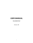
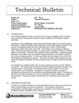
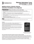
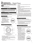
Controls and Displays
MODEL SS7 SERIES
INSTALLATION AND OPERATING
INSTRUCTIONS
Cover/Switch
The clear cover/switch is the manual ON/OFF control.
1. Pull at notch at top edge to remove cover so you can
use the programming buttons.
To replace cover/switch:
2. Set bottom in first.
1
3. Click in the top.
MAN
AM
Features
MODE
DAY
To remove battery:
4. Grasp holder at side bumps
(4a,4b) and pull straight out.
ON
MO
• Automatic or manual operation. Push the clear cover/switch to switch On or Off at any time.
• Program up to 6 On/Off setting pairs (12 automatic switch settings).
• Each setting time can be once a week, every day, every weekday, or only on weekends.
• LCD Digital clock and readout.
• Random feature automatically varies switching times for a “lived-in” look.
• One AA Alkaline battery keeps time, operates timer, and keeps the program for up to 3 years, even without
utility power.
• Can be used for flood (PAR) and compact fluorescent lamps and dimmers.
• Unique “hard contact” output switch allows timer to control most 120 VAC loads.
Also controls many loads 12 to 277 VAC and 12 to 28 Volts DC.
Refer to product label for maximum ratings for various voltages and load types.
ON/OFF
EVENT
RESET
H+
M+
ON/OFF
EVENT
DAY
H+
M+
MODE
ON/OFF
EVENT
RESET
RESET
Installation Instructions - Single Switch or 3-way - to replace an existing switch:
MODE
DAY
H+
M+
Single switch:
3. Connect one of the building wires to the black wire
from the timer, using the wire nuts provided. Connect
the other building wire to the blue wire from the timer.
THE RED TIMER WIRE IS NOT USED FOR SINGLE
SWITCH INSTALLATIONS. Cap the red wire with a
wire nut.
BE SURE THAT ALL THE WIRE NUTS ARE SECURE.
DAY
DAY
ON/OFF
EVENT
RESET
H+
M+
ON/OFF
EVENT
RESET
H+
M+
MODE
ON/OFF
EVENT
RESET
DAY
H+
M+
ON/OFF
EVENT
RESET
H+
M+
ON
RESET
M+
DAY
H+
M+
DAY
ON/OFF
EVENT
Battery
Holder
Battery Replacement
The 1.5 VOLT alkaline battery should operate your timer for 3 years or more under typical conditions. High
or low temperature or frequent use of the manual pushbutton or the 3-way switch will reduce the battery life.
Replace the battery when the digital display is dim, the message ‘lobAt’ (Meaning LOW BATTERY) is displayed,
or if the timer fails to operate. Press any button to clear the ‘lobAt’ message. The timer has built-in memory
protection providing at least 15 seconds to change a weak battery without losing your settings. You do not
need to turn off the load or the power in order to replace the battery, however, do not attempt to switch the
timer on or off while the battery is out or your settings will be lost and the timer will need to be reset.
Function depends on the mode:
CLK mode - Push and release to cycle through the days of the
week: MO,TU,WE,TH, FR, SA, SU. Push and hold to cycle quickly.
PGM mode - Push and release to cycle through all week, weekdays, weekend, individual days of the week and null:
MO TU WE TH FR SA SU (all displayed at once is all week)
MO TU WE TH FR (all displayed at once is weekdays)
SA SU (displayed is weekend)
MO,TU,WE,TH, FR, SA, and SU (are individual days)
-:-- (on clock display is the null setting)
Use null to cancel an unwanted ON or OFF setting. The DAY button does nothing in AUTO, AUTO RAND or MAN modes.
Works in CLK and PGM modes.
Push and release to cycle forward through the hours of the day.
Push and hold to cycle quickly.
AM and PM automatically switch at 12.
If you pass the correct hour, push and hold to cycle around again.
Works in CLK and PGM modes.
Push and release to cycle forward through the minutes.
Push and hold to cycle quickly.
If you pass the correct minute, push and hold to cycle around
again.
ON/OFF/EVENT button
MODE
MAN
AM
H+
Push and release to change the mode (upper line of the display).
CLK mode - To set or change the time.
PGM mode - To set, review or change programmed ON/OFF times.
AUTO mode - Programmed ON/OFF times work. Manual
switching works.
AUTO RAND mode - Programmed ON/OFF times work and
are randomly offset up to 15 minutes. Manual switching works.
MAN mode - Only manual switching works. Programmed
ON/OFF times remain in memory.
The Mode button skips the AUTO modes if the time of day
and/or the ON/OFF times have not been set.
M+ (minute) button
4.Tuck the wires into the wall box leaving room for the timer.
5. Using the screws provided, mount the timer to the wall box then install the wall plate.
Battery (If not supplied with unit.)
6. Grasp battery holder at side bumps (6a, 6b) and pull straight out. Uses a standard AA alkaline battery. Set the
battery in the battery holder (+ towards front of timer). Tuck battery under plastic tab of holder. Insert battery
holder so it clicks into place.
7. Pull at notch at top edge to remove the clear/cover switch so you can
use the programming buttons.
7
8. To stop the flashing display and turn switch to OFF: Push RESET button;
Push MODE so CLK is displayed at the upper left; push H+ to stop the
flashing display; push MODE twice so MAN is displayed at the upper
right; push ON/OFF EVENT so display at upper right says OFF (you may
hear the timer motor run and a clicking sound).
6b
9. Your timer is now ready for use. Return the power to the circuit at the
6a
service panel.
ON/OFF
EVENT
Recessed so you don’t push it accidentally.
Push and release to reset:
When you press RESET:
• The mode switches to MAN.
• The switch is set to ON.
• The clock is set to MO 12:00 AM and flashes.
• All programmed ON or OFF times are set to null
(at null, no switching occurs, clock displays -:--).
(After pushing RESET, you must set the clock then set the
ON/OFF times.)
• If NoOp appears in display, push battery cover in until you
hear a click. Push reset button to clear display. Proceed with
programming.
H+ (hour) button
MODE
3b. Identify the “common” terminal at the other (remote 3-way) switch. Connect the supplied jumper wire from
the common terminal to one of the other two terminals of the switch.
(If the light does not turn on when you get to step 9, turn power off at the fuse or circuit breaker and switch the
jumper wire to the other terminal.)
DAY
Function depends on the mode:
CLK mode - ON/OFF EVENT button does nothing.
PGM mode - Switches in order through the 12 programmable
events 1 ON, 1 OFF, 2 ON, 2 OFF, 3 ON, 3 OFF, 4 ON, 4 OFF, 5 ON, 5 OFF,
6 ON, and 6 OFF.
AUTO mode - Manually turns switch on or off.
AUTO RAND mode - Manually turns switch on or off.
MAN mode - Manually turns switch on or off.
2a
How to set or change the clock
1.
2.
3.
4.
5.
6.
7.
8.
Remove the clear cover/switch.
Push and release MODE button until CLK is displayed (2a).
Push and release DAY button until correct day of week is displayed (3a).
Push and release H+ button until hour and AM/PM are correct (4a).
Push and release M+ button until minutes are correct (5a).
Push and release MODE button to choose AUTO, AUTO RAND or MAN.
Replace clear cover/switch.
Push and release clear cover/switch to switch load ON or OFF if
necessary.
CLK
The timer is a programmable switch.
At any time you can push the clear cover/switch to manually turn the switch ON or OFF, unless selected mode is
CLK or PGM.
You can program up to 12 ON/OFF EVENTS; times when the timer automatically switches the connected lights
(or other electrical devices) ON or OFF (up to 6 ON events and 6 OFF events). An EVENT can be set to switch at:
• any specific time, and day of the week,
• a specific time every day,
• a specific time on weekdays, or
• a specific time on weekends.
See Installation Instructions first if your timer is not already installed, or if the AA Alkaline battery is not
installed.
Manual Override
AUTO RAND
PM
WE
MODE
DAY
ON
ON/OFF
EVENT
RESET
H+
M+
Works like a light switch. Push and release the clear cover/switch
(area over buttons) to switch ON or OFF. Or switch ON and OFF
using the remote switch(es) in multi-switch installations.
•
•
•
•
Works in AUTO, AUTO RAND or MAN modes.
You hear a motor/clicking sound.
ON/OFF display changes.
The program in AUTO or AUTO RAND remains; it automatically switches ON or OFF at next programmed time.
PUSH ON/OFF
5a
PM
4a
WE
3a
MODE
2,6
DAY
ON
ON/OFF
EVENT
RESET
H+
M+
3
4
5
Programming and Operating Instructions
Introduction to Operation and Programming:
4b
2
DAY button
MODE
3-way switch: (See “Other Installations” to use a dimmer or if switching from 3 or more locations)
3a. A three way switch has three wires connected to it. One of the wires is “common” (the terminal has a different colored screw or there are markings on the old switch). Connect the Black wire from the timer to the
common wire. Connect the other two wires to the Blue and Red wires from the timer (it doesn’t matter which
goes to which.)
RED WIRE
COMMON
MOVE
BLUE WIRE
JUMPER WIRE
TO OTHER
TERMINAL
REMOTE
WIRE FROM
IF THIS
3-WAY
“COMMON” OF
SWITCH
SWITCH
OLD SWITCH
DOES NOT
TURN LIGHT
BLACK WIRE
ON
MODE
M+
5
MODE button
7/16”
Trim building wires bare to 7/16”.
MO
H+
DAY
RESET button
RESET
The installation instructions on this page are for replacing a light switch (or 3-way light switch) with the timer. See
“Other Installations” on the next page for wiring diagrams for new construction, switching from 3 or more locations, or using the timer with a dimmer.
BLUE WIRE
RESET
EVENT
Battery Holder
The timer can replace your regular or 3-way light switch (where two switches control the same light) to control
lights for security, or can control an outlet to switch most 120VAC loads up to the maximum rating on the
timer label. The timer can control incandescent lights, fluorescent lights, flood lights (PAR lamps), stereos, or
appliances such as an air conditioner. The timer can also control many loads 12 to 277 VAC and 12 to 28 Volts
DC. Timer may not be used with lighted switches.
You will need to use a Decorator style wall plate with this timer (not supplied).
RED WIRE
(Capped, Not Connected)
ON/OFF
MODE
4a
Push Buttons:
MODE
BLACK WIRE
ON
MO
To re-install battery:
5. Place battery in holder with “+”
end towards front of timer. Insert
battery and holder into timer.
Push at (5) so it clicks
into place.
Introduction
1.TURN OFF POWER by REMOVING FUSE or turning
the CIRCUIT BREAKER OFF.
2. Remove the existing wall switch.
Prepare the ends of the building wiring as shown.
3
MAN
AM
How to set, change, or review ON/OFF times
1. Remove clear cover/switch.
2. Push and release MODE button until PGM is displayed (2a).
2a
[at event 1 ON]
3. If necessary, push and release ON/OFF/EVENT button until event to
set/change is displayed (3a), or push the ON/OFF/EVENT pushbutton
repeatedly to review all the ON/OFF times.
2, 8
4. Push and release DAY button until desired day or group of days is displayed
(4a), or push and release the DAY button until “-:--” is displayed, if you would
like to cancel this ON or OFF time.
4
5. Push and release H+ button until desired event hour and AM/PM are
displayed (5a).
6. Push and release M+ button until desired minutes are displayed (6a).
7. Push and release ON/OFF/EVENT button to choose the next event to set 5a
or change (7a).
8. Push and release MODE button to choose AUTO, AUTO RAND, or MAN.
9. Replace clear cover/switch.
4a
10. Push and release clear cover/switch to switch load ON or OFF if
necessary.
3a
PGM
ON
MODE
DAY
ON/OFF
EVENT
RESET
H+
M+
3, 7
6
5
6a
7a
PGM
OFF
PM
MO TU WE TH FR
(Example)
LOAD MAINTENANCE
WARNING1 DO NOT USE THE TIMER TO TURN OFF POWER FOR MAINTENANCE (repairs, removing broken
bulbs, etc.). ALWAYS TURN POWER OFF AT THE SERVICE PANEL BY REMOVING A FUSE OR SWITCHING OFF
A CIRCUIT BREAKER BEFORE DOING ANY CIRCUIT REPAIRS.
Error Messages
The ‘lobAt’ message means the battery is low and needs to be replaced. Uses one standard AA alkaline battery.
The display is ‘noOp’ (Meaning no Operation) if the timer fails to operate. This can happen in very cold temperatures. Normal timer operation should resume at normal temperatures. Press any button to clear the message(s).
If the ‘noOp’ remains at normal temperatures with a fresh battery, timer needs to be replaced.
Other Installations
4 or more switch installation:
MULTISWITCH APPLICATIONS USING THE ELECTRONIC TIMER ARE WIRED DIFFERENTLY
THAN WHEN USING CONVENTIONAL TOGGLE SWITCHES. READ THE FOLLOWING
INSTRUCTIONS CAREFULLY.
For 4 or more switch installations use the preceding 3 switch installation diagram and wire 4-way switches
between the two 3-way switches.
Note:THE REMOTE SWITCH(ES) MAY NOT FUNCTION RELIABLY WHEN THE ACCUMULATED WIRE
LENGTH TO THE REMOTE SWITCH(ES) EXCEEDS 30 FEET OR IF THE WIRING TO THE REMOTE
SWITCH(ES) IS BURIED UNDERGROUND. Consult factory for details.
Multiple timers may be mounted in adjacent junction box slots.
No derating is required for multiple timers.
Wiring diagram, 2 switch installation (3-way):
Note: Used remote switches from a previous conventional installation may not function reliably with an electronic
timer. Try a brand new remote switch if function is intermittent.
LOAD
JUMPER
BLUE
BLAC
LINE
NEUTRAL
TIMER
Installations including a Dimmer:
COMMON
RED
3-WAY SWITCH
• The load size and type must not exceed the rating of the dimmer.
(Typically 600 watts, 120 VAC, 60 Hz, incandescent lamps only.)
• If the dimmer is placed in it’s ‘OFF’ position, the timer cannot operate the lights.
• If the dimmer is set too low, the lights may not turn back on under timer control. If necessary, use a
premium quality dimmer that can be turned on at very low settings.
NOTE: For new construction or to replace a dimmer switch, a lighted switch, or a 3-way switch without screw
terminals, a single pole switch can be used at the remote location, as shown below.
LIGHT
Wiring diagram, 2 switch installation (3-way) using a single pole remote switch:
BLUE
BLACK
LOAD
TIMER
LINE
BLUE
LINE
DIMMER
NEUTRAL
RED
BLACK
NEUTRAL
TIMER
(Capped, Not Connected)
RED
SINGLE POLE SWITCH
Multi-switch installation using a dimmer :
A 3-way dimmer should not be used. If a multi-switch installation is required, use the following diagram.
Wiring diagram, 3 switch installation:
LIGHT
For 3 or more switch operation, AN ADDITIONAL WIRE MUST BE ADDED between the load and the timer.
The jumper wire is not required for these applications.
LINE
ADDITIONAL WIRE
BLUE
BLACK
TIMER
LOAD
NEUTRAL
DIMMER
RED
BLUE
REMOTE SWITCH
BLACK
LINE
TIMER
NEUTRAL
Special applications
RED
TWO 3-WAY SWITCHES
For existing 3 switch installations replace one 3-way switch with the timer and replace the 4-way switch with a
3-way switch.
Because of it’s unique “hard contact” switch feature, your timer may be used for applications not previously possible
for electronic wall timers, such as use with dimmers, use without utility power, use on circuits other than 120 volts,
controlling relays or contactors, or to control DC voltage (for example in recreational vehicles). See instructions
above for dimmer applications. For DC and high voltage applications please note the reduced load ratings on product label. Consult factory for application details.
TROUBLESHOOTING GUIDE
SYMPTOM
POSSIBLE CAUSE
REMEDY
Timer does not operate, display is dim, blank or unreadable, display shows nonsense or ‘lobAt’, or timer operates erratically.
Battery is worn out, missing or is installed backwards, or timer
was operated while battery was removed.
Install a fresh AA size alkaline battery in the direction indicated. Press RESET button, then reprogram timer.
Timer does not switch but display is normal.
Timer not in AUTO, AUTO RAND(om), or MAN(ual) mode.
Use MODE pushbutton to select the desired operating mode.
Timer works manually but does not follow scheduled program.
Timer not in AUTO or AUTO RAND(om) mode.
Use MODE pushbutton to select AUTO or AUTO RAND
Timer won’t enter the AUTO or AUTO RAND modes when
MODE button is pushed.
Time of day and/or switching times are not programmed.
Make sure time of day and at least one scheduled activity are
programmed.
Timer switches at incorrect times or skips some switching
times.
Programmed schedule(s) are incorrect.
Review / Revise ALL 6 ON/OFF switching time pairs by repeatedly pushing the ON/OFF/EVENT button while in PGM mode.
Timer is in AUTO RAND(om) mode (Varies switching times up
to +/- 15 minutes).
Use MODE pushbutton to select AUTO mode.
Load state doesn’t match programmed state immediately after
programming the time or schedule.
Timer does not “catch up” to the programmed load state. The
load will remain in it’s state prior to entering the PGM mode.
The timer will begin following the scheduled program at the
next contrary ON/OFF time.
After entering your schedules or the time, then returning to
the AUTO modes, push the ON/OFF/EVENT button to change
the load state if necessary.
Display shows ‘no Op’.
Mechanism is inoperative.
If timer is in a very cold environment, try again when warmer.
If not, and if the battery is good, the timer should be replaced.
Push in battery cover until you hear a click. Push reset button
to clear display and reprogram the unit. Replace device if NoOp
will not clear from display.
Timer operates, but light doesn’t come on in dimmer applications.
Dimmer is turned off or is set too low to turn back on or the
bulb is burned out.
Make sure timer display shows ‘ON’ then check dimmer operation at full brightness setting. If timer control is required at
very low brightness settings, use a premium quality dimmer
that can be turned on when set low.
Load only operates when the remote (3-way) switch is in one
position or timer ignores the remote switch.
Remote switch is wired incorrectly.
Recheck wiring, especially for the jumper, per “Installation
Instructions - 3-Way Switch” and “Other Installations”.
Timer ignores remote (3-way) switch even though it is wired
correctly.
Excessive length of wire (greater than 30 feet) or buried wiring
to the remote switch.
Eliminate condition, replace the buried cable, do without the
remote switch, or consult factory for other options.
Remote switch is defective or worn out.
Replace remote switch.
Load turns off immediately after being turned on.
Remote switch or timer wired incorrectly, excessive length of
wire (greater than 30’) or buried wiring to remote switch, or
defective timer.
If the problem persists with the red wire disconnected or with
a ‘remote’ switch temporarily connected right at the timer,
replace the defective timer, otherwise try the above remedies.
Battery holder is difficult to snap in place
Battery not seated in holder, holder misaligned, or contact tabs
of holder are bent.
Make sure the “+” end of battery is tucked under the plastic tab
of the holder. Line up tabs on bottom of holder with notches
in timer housing when pushing in. Straighten bent contact tabs.
FULL ONE YEAR WARRANTY
If within one (1) year from date of purchase, this product fails due to a defect in materials or workmanship, Intermatic Incorporated will repair or replace it free of charge.
The warranty does not apply to: (a) damage caused by accident, abuse, mishandling, dropping; (b) units which have been subject to unauthorized repair, opened, taken apart; (c) units not used in accordance with directions; (d) damages exceeding the cost of the product. Some states do not allow a limitation of damages, so the foregoing limitation may not apply to you. This warranty gives you specific
legal rights, and you may have other rights which vary from state to state.
This warranty service is available by either: a) returning the product to the dealer from whom the product was purchased or (b) mailing postage prepaid to the authorized service station listed below.
Be sure to wrap the product securely when mailing to avoid shipping damage. This warranty is made by Intermatic Incorporated, Spring Grove, Illinois, 60081-9698.
AUTHORIZED SERVICE STATION
INTERMATIC INCORPORATED
INTERMATIC PLAZA
SPRING GROVE, ILLINOIS 60081-9698
158SS10109