1
PNEUMERCATOR
MULTI POINT
LEAK SENSOR
MONITORING
SYSTEM
Liquid Level Control Systems
INSTALLATION MANUAL
DRAWING NO. 20068 REV. N/C
MODEL LC2000
© COPYRIGHT 2007 PNEUMERCATOR CO., INC.
120 FINN COURT, FARMINGDALE, NY 11735
TEL: (631) 293-8450
FAX: (631) 293-8533
http://www.pneumercator.com
LC2000 Installation.doc
01-17-07
INSTALLATION MANUAL
LC2000
Note: A separate OPERATING MANUAL is available, but NOT required for LC2000 installation.
TABLE OF CONTENTS
Page
SAFETY INFORMATION ............................................................................................1
Section 1
1.1
1.2
1.3
PRODUCT DESCRIPTION ...........................................................................................
General System Overview...........................................................................................2
Control Console...........................................................................................................3
Liquid Leak Sensors ....................................................................................................5
Section 2
2.1
2.2
2.3
2.4
2.5
2.6
INSTALLATION DETAILS
Installation Checklist....................................................................................................7
Control Console Installation ........................................................................................8
Leak Sensor Installation – Steel Tanks .......................................................................9
Leak Sensor Installation – Piping Sumps and Dispenser Pans, Vaulted Tank .........10
Leak Sensor Installation – Fiberglass Underground Tanks.......................................11
Leak Sensor Installation – Fiberglass Underground Tank Reservoirs ......................12
Section 3
3.1
3.2
3.3
3.4
3.5
3.6
3.7
WIRING INSTALLATION AND DIAGRAMS
System Intrinsic Safety Wiring...................................................................................14
Power Wiring .............................................................................................................19
Sensor Wiring & Splices ............................................................................................20
Programmable Relay Outputs/Contact Closure Inputs..............................................23
Data Communications Wiring ....................................................................................24
System Setup ............................................................................................................25
Carrier Insert Instructions ..........................................................................................26
INSTALLATION MANUAL
LC2000
IMPORTANT SAFETY INFORMATION
This manual contains instructions for installing electrical hardware in explosion
hazard areas.
The following warnings must be considered to be in compliance with accepted
codes.
Any inquiries about this manual, or to return defective equipment should be
directed to:
PNEUMERCATOR COMPANY
120 FINN COURT
FARMINGDALE, NY 11735
Attention: Technical Services
TEL: (631) 293-8450
FAX: (631) 293-8533
TOLL FREE: (800) 209-7858
www.pneumercator.com
WARNING
Installation must be in strict accordance with this manual as adopted from the
following codes:
- ISA RP12.6, "Installation of intrinsically Safe Instrument Systems in Class I
Hazardous Locations."
- UL - Underwriters Laboratories
- NFPA 70, "National Electric Code."
- NFPA 30A, "Automotive and Marine Service Station Code."
FAILURE TO COMPLY MAY RESULT IN PERSONAL INJURY, PROPERTY LOSS
AND EQUIPMENT DAMAGE.
WARNING
Alteration, modification or replacement with non-factory components could
impair the intrinsic safety of this equipment, void the warranty and void the UL
Listing. FAILURE TO COMPLY MAY RESULT IN PERSONAL INJURY,
PROPERTY LOSS AND EQUIPMENT DAMAGE.
LC2000 Installation.doc
01-17-07
PAGE 2
INSTALLATION MANUAL
LC2000
SECTION 1 – PRODUCT DESCRIPTIONS
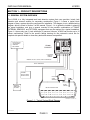
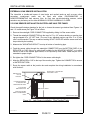
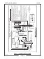
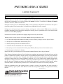
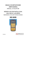
1.1 GENERAL SYSTEM OVERVIEW
The LC2000 is a fully integrated tank leak detection system that uses precision in-tank leak
detection and external sensors for secondary containment. Figure 1-1 shows a typical block
diagram of how a system should be configured for installation. This diagram is not a detailed wiring
diagram, which is found in Section 3 of this manual. Figure 1-1 is to guide the installer in planning
the actual installation, and give a general overview of the possible combinations of TANKS,
EXTERNAL SENSORS, and OPTIONAL equipment that may be required for a typical installation.
Figure 1-1 shows only one (1) tank with three (3) sensors: however, LC2000 can monitor up to 16
sensor combinations. Refer to the specific design drawing for the customer's actual site for
complete site-specific details on how many tanks and sensors are specified.
PNEUMERCATOR
Liquid Level Control Systems
LC 2000
NORM
LEAK/POINT LEVEL CONSOLE
PROD
WATER
NORM
1
PROD WATER
9
FAULT
DATA DISPLAY /
GATHERING &
CONTROL
EQUIPMENT
2
10
3
11
4
12
13
5
14
6
LC2000
CONSOLE
15
7
16
8
SENSOR NO/NC FAULT
PAPER
FEED
PRINT
PROGRAM
SENSOR NO/NC FAULT
RESET
PGM
TEST
SENSOR
SELECT
PROGRAM
SELECT
ON/OFF
115/230 VAC
(50/60 Hz)
POWER
MODEM / RS-232 / RS-485 / RELAY CONTACTS
RELAY CONTACTS
SENSOR
INPUTS FROM
OTHER TANKS
PIPING
SUMP
SENSOR
REMOTE
MOUNTED
ALARMS
FLOAT
SWITCH
LIQUID STORAGE TANK
DRAWING NO. 20069 REV. N/C
Figure 1-1 - Typical System Block Diagram
LC2000 Installation.doc
01-17-07
PAGE 3
INSTALLATION MANUAL
LC2000
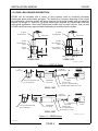
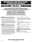
1.2 CONTROL CONSOLE DESCRIPTION
Figure 1-2 illustrates the standard LC2000 outline and dimensions. All standard configurations are
equipped with 4 leak sensor inputs, 1 RS-232 serial port, 1 RS-485 serial port, 2 Fully
programmable Relay outputs/2 Dry contact inputs, NEMA 12 enclosure. There are four (4) basic
configurations available:
LC2000-1
LC2000-2
LC2000-3
LC2000-4
“Black Box” Remote Acquisition Unit w/o display.
Front Panel Display w/o printer.
Front Panel Display with impact printer.
Front Panel Display with impact printer & autowinder.
WARNING
Installation MUST be done by qualified personnel familiar with local wiring
codes and explosion hazard electrical safety practices. FAILURE TO COMPLY
MAY RESULT IN PERSONAL INJURY, PROPERTY LOSS AND EQUIPMENT
DAMAGE.
The standard LC2000 console enclosure is NEMA 12-rated for indoor installation. An optional
NEMA 4/4X enclosure is available for outdoor installation. Confirm enclosure rating on the approval
label located on the exterior, left-hand side of the enclosure before installation outdoors. See Figure
1.2 below for mounting flange locations and dimensions.
OPTIONAL AUTOWIND PRINTER
INDICATOR LIGHTS
EMERGENCY CONTACT
VIEWING WINDOW
CHANNELS 1-8 ADVISORY
LABEL VIEWING WINDOW
OPERATING MEMBRANE BUTTONS
CHANNELS 9-16 ADVISORY
LABEL VIEWING WINDOW
NON I.S. SECTION
NON I.S. & I.S. SECTION
PARTITION LINE
(SHOWN FOR REFERENCE)
ANNUNCIATOR
5/16" DIA. [7.87 DIA.] MOUNTING
HOLES (4) PLACES
B
A
C
CONDUIT OPENINGS
A = 1 1/8" DIA. HOLE
FOR 3/4" NPT *
CONDUIT FITTING
B = 7/8" DIA. KNOCKOUT
FOR 1/2" NPT *
CONDUIT FITTING
C = 1 1/8" DIA. KNOCKOUT
FOR 3/4" NPT *
CONDUIT FITTING
* OR EQUIVALENT
9 3/4
[247.63]
C
A
KEYED
DOOR LOCK
STROBE
DOME
4 23/32
[119.55]
(5 7/32 [132.60]
OVER
ANNUNCIATOR)
11 13/16
[300.22]
9 27/32 [249.94]
10 5/8 [269.75]
11 11/32 [288.04]
I.S. SECTION
(LOW VOLTAGE)
DIMENSIONS: INCHES [MM]
DRAWING NO. 20070 REV. N/C
Figure 1-2 - LC2000 Console Outline
WARNING
The console is designed for Ordinary Location, Non-Hazardous installation
only, as defined by Underwriters Laboratories (UL) and the National Electrical
Code (NEC). DO NOT install where flammable vapors may be present. FAILURE
TO COMPLY MAY RESULT IN PERSONAL INJURY, PROPERTY LOSS AND
EQUIPMENT DAMAGE.
LC2000 Installation.doc
01-17-07
PAGE 4
INSTALLATION MANUAL
LC2000
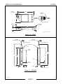
The console should be located in an area that is easily accessible to the personnel responsible for
operation and maintenance of the system. Metal conduiting is recommended and may be required
by local codes. All outdoor conduits must be watertight.
All conduit entries are provided on the bottom of the enclosure. Remove conduit knockouts only for
those entries being used. If a knockout is removed but the entry will not be used, it must be sealed
with an appropriate plug.
WARNING
Do not drill or modify enclosure. Use only knockouts provided. FAILURE TO
COMPLY WILL VOID WARRANTY AND MAY PRESENT A SAFETY HAZARD
RESULTING IN PERSONAL INJURY, PROPERTY LOSS AND EQUIPMENT
DAMAGE.
WARNING
Conduit entries must only be used for their designated purpose in order to
assure safe operation and to maintain safety certification. FAILURE TO
COMPLY WILL VOID WARRANTY AND MAY PRESENT A SAFETY HAZARD
RESULTING IN PERSONAL INJURY, PROPERTY LOSS AND EQUIPMENT
DAMAGE.
A1, B2 & B3
DENOTES CONDUIT
KNOCKOUTS
A1
B4
B3
B2
B1
B1 & B4
DENOTES CONDUIT
HOLES
NON-INTRINSICALLY SAFE
CONDUIT OPENINGS AND
DESIGNATED USES:
INTRINSICALLY SAFE
CONDUIT OPENINGS AND
DESIGNATED USES:
1/2" NPT CONDUIT SIZE *
A1 = COMMUNICATIONS CABLES
3/4" NPT CONDUIT SIZE *
B1 & B2 = I.S. SENSOR INPUTS
3/4" NPT CONDUIT SIZE *
B3 = RELAY OUTPUTS AND NON I.S. SLOT
B4 = POWER AND I.S. GROUNDS
* OR EQUIVALENT
DRAWING NO. 20071 REV. N/C
Figure 1-3 - LC2000 Designated Conduit Locations
LC2000 Installation.doc
01-17-07
PAGE 5
INSTALLATION MANUAL
LC2000
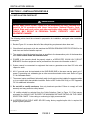
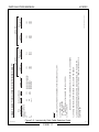
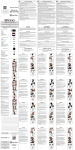
1.3 LIQUID LEAK SENSOR DESCRIPTION
LC2000 can be integrated with a variety of liquid sensors used for monitoring secondary
containment areas around tanks and pipes. The maximum is 8 sensors depending on the overall
job configuration; check the specific job design drawings for the actual number and type specified.
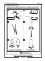
Figures 1-4 through 1-7 show four (4) typical sensor types provided by Pneumercator with their
most typical applications. Other non-Pneumercator models may be used; however, their use with
LC2000 should have been approved before attempting to wire them into the system.
25' LONG
18 AWG CABLE
25' LONG
18 AWG CABLE
CABLE GRIP
CABLE GRIP
NYLON
TEFLON
304 STAINLESS
STEEL
304 STAINLESS
STEEL
4.00"
BUNA N
FLOAT
4.00"
316 STAINLESS
STEEL FLOAT
1/2" LIQUID
TRIP POINT
1/2" LIQUID
TRIP POINT
Ø1.75"
Ø1.50"
LS600 LDBN
LS600 LDSS
DRAWING NO. 20006 REV. A
Figure 1-4 – LS600 LD Series
.62"
(HEX FLAT)
3.00"
ES825-100F
Ø.75"
3 CONDUCTOR
CABLE
REMOVABLE
PULL RING
PASS-THRU OPENING SIZE
3/4" NPT MINIMUM
PULL RING
REMOVED
20' OR 25'
22 AWG CABLE
SHRINK TUBE
("C" & "X" VERSIONS ONLY)
CONVOLUTIONS ACCEPTS 1/2" ENT
PULL RING
REMOVED
20' OR 25'
22 AWG CABLE
3.50"
3 CONDUCTOR
CABLE
PASS-THRU OPENING SIZE
3/4" NPT MINIMUM
REMOVABLE
PULL RING
ES825-200F
1/4" NPT
1/4" NPT
SHRINK TUBE
("X" VERSION ONLY)
END ACCEPTS 1/2" ENT
DRAWING NO. 20007 REV. A
Figure 1-5 – ES825 Series
LC2000 Installation.doc
01-17-07
PAGE 6
INSTALLATION MANUAL
LC2000
3.02"
Ø.130"
PULL HOLE
25' LONG
CABLE
1.50"
CABLE GRIP
.236 REF.
1/2" LIQUID
TRIP POINT
.40"
DRAWING NO. 20008 REV. N/C
Figure 1-6 – LS610
16' LONG
22 AWG CABLE
16' LONG
22 AWG CABLE
CABLE GRIP
CABLE GRIP
PVC HOUSING
FLOAT
HIGH
ALARM
18.25"
18.25"
15.00"
11.00"
15.00"
FLOAT
LOW
ALARM
2.25"
Ø2.88"
2.25"
Ø2.88"
DRAWING NO. 20009 REV. N/C
Figure 1-7 – RSU800
LC2000 Installation.doc
01-17-07
PAGE 7
INSTALLATION MANUAL
LC2000
SECTION 2 – INSTALLATION DETAILS
2.1 INSTALLATION CHECKLIST
WARNING
Do NOT apply power to the LC2000 until its installation has been checked and
found to be in accordance with these instructions; National Electric Code;
Federal, State and Local codes; and other applicable safety codes. FAILURE TO
COMPLY MAY RESULT IN PERSONAL INJURY, PROPERTY LOSS AND
EQUIPMENT DAMAGE.
The following points should be reviewed in preparation for installation, and again when installation
is complete.
1. Review Figure 3-1 to ensure that all of the safety/wiring requirements have been met.
2. Check that all equipment at job site matches the DESIGN DRAWING SPECIFICATIONS for the
tank sizes and control features required.
3. The console should be located as close as possible to the demarcation point of the hazardous
area. Never mount inside the hazardous area.
4. POWER to the console should be properly wired to a DEDICATED 120/240 VAC CIRCUIT
BREAKER. No other equipment can be powered from the same circuit breaker as the LC.
5. System cannot be connected to equipment that uses or generates more than 250 volts with
respect to earth.
6. All LC grounds must be terminated at the GND BUSS BAR in the same service panel as LC
power. A grounding rod, coldwater pipe or other connection should not be used. Refer to Figure
3-3 for illustrated details.
7. The sensor inputs are different intrinsically safe circuits and must be installed in separate cables
or in one cable which has suitable insulation. Refer to NEC Article 504-30 (b) or CEC Appendix
F6.3 for additional information.
8. Do not drill or modify enclosure. Use only knockouts provided. Failure to comply will void
warranty and may present a safety hazard.
9. I.S. cabling should be selected from the Cable Selection Chart in Figure 3-2. Each sensor
wire/cable run SHOULD NOT EXCEED THE MAXIMUM DISTANCE RATING ON THE CABLE
SELECTION CHART. Color-coding or numbering is highly recommended.
10. WATERPROOFING FIELD WIRE SPLICES using factory supplied splice kits is required for
proper system operation.
LC2000 Installation.doc
01-17-07
PAGE 8
INSTALLATION MANUAL
LC2000
2.2 CONTROL CONSOLE INSTALLATION
The console is the center of operations for any tank monitor system therefore its location should be
selected for the operators convenience, or as specified on the DESIGN DRAWINGS.
Select a flat wall surface and prepare it with four wall-mounting inserts to accept up to 1/4-inch size
bolts. Allow sufficient room for door to open and for conduit runs to enter ONLY THE CONSOLE
BOTTOM. See Figure 1-2 for console dimensions.
Note that the console is divided into two electrical areas:
NON INTRINSICALLY SAFE (LEFT SIDE)
INTRINSICALLY SAFE (RIGHT SIDE)
for Power and Control
for Sensor signals
Figure 2-1 shows the console interior, again indicating the power and signal separation. THIS
SEPARATION MUST BE MAINTAINED when conduits are connected. Refer to Section 3 for
electrical conduit and wiring.
LOCK
DISPLAY
COVER
I.S. COMPARTMENT COVER
(SHOWN OPENED)
OPTIONAL
PRINTER
EDIT
ENABLE / SAVE
BUTTON
I.S. SENSOR
INPUTS
RS-232 CONNECTION
COMMUNICATIONS PORT
CONNECTOR
FUSE HOLDER
ON/OFF SWITCH
POWER
I.S. GROUNDS
RS-485 CONNECTION
(2) STANDARD
NON I.S. RELAY I/Os
NON I.S. SLOT
CONNECTOR
DRAWING NO. 20072 REV. N/C
Figure 2-1 - Control Console Interior
LC2000 Installation.doc
01-17-07
PAGE 9
INSTALLATION MANUAL
LC2000
EXTERNAL LEAK SENSOR INSTALLATION
The interstitial or double-wall space of steel tanks and vaulted tanks as well as many other
secondary containment areas can be fitted with either DISCRIMINATING or
NON-DISCRIMINATING leak sensors. Also, for float type non-discriminating sensors, switch
actuation may be factory set for either NORMALLY OPEN or NORMALLY CLOSED.
2.3 LEAK SENSOR INSTALLATION IN STEEL AND VAULTED TANKS
Check the specific design drawings for the job, or choose the sensor type desired from Figures 1-4
and 1-5. Install sensor per Figure 2-2 as follows:
1. Remove the watertight CORD CONNECTOR supplied by sliding it off the sensor cable.
2. Thread the watertight CONNECTOR into the top of a 2" by 1/2" reducer bushing or monitor pipe
cap pre-tapped for a 1/2" NPT hole. (The use of any standard monitor cap from 2" to 4" pipe
size is recommended. The cap or reducer bushing IS NOT SUPPLIED with the sensor and must
be provided by the installer).
3. Measure the "MOUNTING HEIGHT" from top to bottom of monitoring pipe.
4. Feed the sensor cable through the watertight CONNECTOR from the BOTTOM SIDE of the
REDUCER (or CAP) fitting to a cable length suitable for the MOUNTING HEIGHT; or to allow
sensor to rest on the monitor pipe bottom; or as required by local codes. Cable may be cut or
extended to proper length.
5. Re-tighten the CORD CONNECTOR to fix the sensor cable length.
6. Mate the REDUCER or CAP to the top of the monitor pipe. Tighten the CONNECTOR to ensure
a WATERTIGHT SEAL.
7. Route the sensor cable to the junction box and complete the wiring installation in accordance
with Section 3.
WATERTIGHT JUNCTION BOX
AND CONDUIT SEAL
MONITOR PIPE
CAP OR
REDUCER
12" MINIMUM MANHOLE
IS REQUIRED FOR
UNDERGROUND TANKS
2" OR LARGER
MONITORING PIPE
MOUNTING HEIGHT
TANK LEAK SENSOR
MODELS LS600LDBN OR
ES825
DOUBLE WALL TANK
DRAWING NO. 20016 REV. B
Figure 2-2 - Leak Sensor Installation - Steel Vaulted Tanks
LC2000 Installation.doc
01-17-07
PAGE 10
INSTALLATION MANUAL
LC2000
2.4 LEAK SENSOR INSTALLATION IN PIPING SUMPS AND DISPENSER PANS
Check the specific design drawings for the job, or choose the sensor type desired from Figures 1-4
and 1-5. Install sensor per Figure 2-3 as follows:
1. Measure the "MOUNTING HEIGHT" from conduit or junction box to the bottom of the SUMP (or
MANHOLE, VAULT or DISPENSER PAN).
2. Feed the sensor cable through the watertight CONNECTOR to length suitable for the
MOUNTING HEIGHT; or to allow sensor to rest on the containment bottom; or as required by
local codes. Feed an additional 12 inches past the CONNECTOR for splicing inside the junction
box; cable may be cut to proper length.
3. Thread the CONNECTOR into the WATERTIGHT JUNCTION BOX and tighten the
CONNECTOR cord grip over the cable to insure a WATERTIGHT SEAL. The sensor should
rest on the containment floor or as required by local codes.
4. Complete the wiring installation in accordance with Section 3.
1/2" NPT LIQUID
TIGHT CONNECTOR
WATERTIGHT JUNCTION BOX
AND CONDUIT SEAL
SENSOR FLEXIBLE CABLE
MANHOLE
PIPING SUMP OR
DISPENSER PAN
LEAK SENSOR
MODELS:
LS600LDBN OR
ES825
MOUNTING HEIGHT
DRAWING NO. 20017 REV. B
Figure 2-3 - Leak Sensor Installation in Piping Sumps, Manholes, and Dispenser Pans
LC2000 Installation.doc
01-17-07
PAGE 11
INSTALLATION MANUAL
LC2000
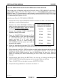
2.5 LEAK SENSOR INSTALLATION IN FIBERGLASS TANK ANNULUS
The annular space of fiberglass tanks can be fitted with either a "DRY ANNULUS" type sensor,
models ES825 (Figure 1-5) and LS610 (Figure 1-6), or a "WET RESERVOIR" sensor model
RSU800 (Figure 1-7). The wet reservoir is also referred to as the HYDROSTATIC METHOD. Check
the specific design drawings for the job, or choose the type sensor desired from Figures 1-5 through
1-7. Install sensor per Figures 2-4 or 2-5.
Instructions per Figure 2-4, DRY ANNULUS SENSOR:
1. Calculate the sensor cable's MOUNTING LENGTH from tank size data so the sensor rests at
tank bottom; or use the following method.
Determine the cable's MOUNTING LENGTH by
adding the cable measurement M from the table at
the right to the RISER HEIGHT. Mark the cable at
that length. DO NOT CUT THE CABLE.
CABLE MEASUREMENT
FROM END OF SENSOR
Tank Dia.
Cable M
4 Feet
81 in.
6 Feet
118 in.
8 Feet
150 in.
10 Feet
194 in.
12 Feet
222 in.
2. Remove the watertight CORD CONNECTOR
supplied by sliding it off the cable.
3. Thread the CONNECTOR into the top of a 2" by
1/2" reducer bushing or riser pipe cap pre-tapped
for a 1/2" NPT hole. (The use of any standard
monitor cap from 2" to 4" pipe size is
recommended. The cap or reducer bushing IS
NOT SUPPLIED with the sensor and must be
provided by the installer).
4. At riser top, attach the annular space PULL CORD
(this is part of the tank supplier's pre-installed accessories) to the sensor's PULL HOLE.
5. Pull the free end of the PULL CORD out of the riser while feeding the sensor into the riser and
through the annular space until the sensor is at the bottom centerline of the tank. The
MOUNTING LENGTH MARK should be about 5 INCHES above the open riser. Adjust its
position as necessary and, without disconnecting the PULL CORD, coil its excess inside the
riser pipe.
6. Feed the sensor cable through the BOTTOM of the riser cap (or bushing), and through the
CORD CONNECTOR while positioning cap over the riser pipe. Mate riser and cap.
7. Tighten CONNECTOR over the cable to ensure a WATERTIGHT SEAL.
8. Complete the wiring installation in accordance with Section 3.
LC2000 Installation.doc
01-17-07
PAGE 12
INSTALLATION MANUAL
LC2000
1/2" NPT LIQUID TIGHT CABLE GRIP
(USE 1/2" X 3/8" NPT REDUCER FOR 3/8" CABLE GRIPS)
WATERTIGHT JUNCTION BOX AND
VAPOR SEAL
RISER PIPE CAP W/
LIQUID TIGHT CABLE GRIP
1/2" OR 3/4" CONDUIT TO CONSOLE
MANHOLE
OPTIONAL PADLOCK
(BY CUSTOMER)
RISER HEIGHT
COIL & SECURE EXCESS PULL CORD
DO NOT REMOVE THE PULL CORD
4" SCHEDULE 40 OR
2" SCHEDULE 40
RISER PIPE
LEAK SENSOR CABLE
PULL CORD
LEAK SENSOR MODELS
LS610 OR ES825
TANK ANNULUS
DRAWING NO. 20018 REV. C
Figure 2-4 - Dry Leak Sensor Installation in Fiberglass Tanks
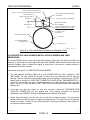
2.6 HYDROSTATIC LEAK SENSOR INSTALLATION IN FIBERGLASS TANK
RESERVOIRS
The model RSU800 sensor uses a dual float that senses a HIGH and LOW liquid level within the
reservoir. If a tank leak occurs through either wall of the DOUBLE-WALL tank the liquid level in the
reservoir changes. When it reaches the upper or lower limits of the sensor a contact closure is
transmitted to the control console.
Instructions per Figure 2-5, HYDROSTATIC LEAK SENSOR:
1. The tank reservoir should be fitted with a 4 inch RISER PIPE and CAP, supplied by THE
INSTALLER. The riser should be at least 12 inches long as measured from the reservoir
opening. The riser cap may be any standard type, but as a minimum it should have a 3/8" NPT
tapped hole to accept the CORD GRIP CONNECTOR SUPPLIED BY PNEUMERCATOR, or
contain its own suitable cord grip. (An alternate method is to drill and tap the wall of the riser
pipe). The use of a riser cap with a VENT TUBE is only recommended where local installation
requires one.
2. If the riser cap does not contain its own cord connector, thread the PNEUMERCATOR
SUPPLIED CONNECTOR into the tapped hole using sealing compound as required.
(Alternately, the CONNECTOR may be threaded into the sidewall of the riser).
3. Slowly lower the sensor into the riser until it rests on the reservoir bottom. The top portion
should extend into the riser pipe for support from tipping over. The liquid level in the reservoir
should be at about 7 inches up the sensor's height for optimum performance. (See Figure 1-7
for float travel set point limits).
LC2000 Installation.doc
01-17-07
PAGE 13
INSTALLATION MANUAL
LC2000
4. Feed the sensor cable through the BOTTOM of the riser cap (or pipe wall), and through the
CORD CONNECTOR. Leave just enough slack inside the riser pipe so the sensor remains on
the bottom, and will not tip over.
5. Mate the riser and cap; tighten the CONNECTOR over the cable to ensure a WATERTIGHT
SEAL.
6. Complete the wiring installation in accordance with Section 3.
1/2" NPT LIQUID TIGHT CABLE GRIP
(USE 1/2" X 3/8" NPT REDUCER FOR 3/8" CABLE GRIPS)
WATERTIGHT JUNCTION BOX AND
CONDUIT SEAL FITTING
RISER PIPE CAP W/
LIQUID TIGHT CABLE GRIPS &
VENT TUBE
1/2" OR 3/4" CONDUIT
LEAK SENSOR CABLE
OPTIONAL PADLOCK (BY CUSTOMER)
MIN. 12"
MANHOLE
4" SCHEDULE 40 RISER
PIPE 12" MIN. LENGTH
LEAK SENSOR
MODEL RSU800
RESTS ON BOTTOM
OF RESERVOIR
7"
RECOMMENDED
HYDROSTATIC
FILL LIQUID
DEPTH IN
RESERVOIR
FIBERGLASS TANK
DRAWING NO. 20019 REV. C
Figure 2-5 - Hydrostatic Leak Sensor Installation in Fiberglass Tanks
LC2000 Installation.doc
01-17-07
PAGE 14
INSTALLATION MANUAL
LC2000
SECTION 3 WIRING INSTALLATION AND DIAGRAMS
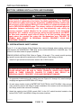
CAUTION
Leak sensors connected to the LC2000 are usually installed in explosion hazard
areas typical of hydrocarbon fuel tanks. For these applications, it is CRITICAL
that electrical conduit and wiring be installed by qualified installers familiar with
all provisions of the National Electrical Code relating to equipment intended for
use in EXPLOSION HAZARD areas. The primary concern is to maintain physical
separation between intrinsically safe and non-intrinsically safe wiring by
running separate conduit attached to the control console at the designated
knockouts. ALL conduits carrying sensor wiring into the hazardous area MUST
be fitted with standard vapor seal-off fittings at all field junction boxes and
again where the conduit first enters the non-hazardous area. FAILURE TO
COMPLY MAY RESULT IN PERSONAL INJURY, PROPERTY LOSS AND
EQUIPMENT DAMAGE.
3.1 SYSTEM INTRINSIC SAFETY WIRING
Figure 3-1 is a typical System Wiring Diagram that must be followed when running conduit and
wires between the HAZARDOUS TANK area and the NON-HAZARDOUS CONSOLE area. This
follows UL and other codes for proper installation.
SENSOR WIRING INSTALLATION. Refer to Figures 1-3 through 1-7 for console conduit openings
and specific sensors that will be wired into the LC2000 system. Install wiring as follows:
1. Install 3/4" rigid conduit from all sensor areas to the LC2000 console.
CAUTION
All sensor wiring from the LC2000 console may be run in the same conduit. NO
OTHER WIRING MAY BE RUN IN THESE CONDUITS. NEVER RUN POWER
WIRES IN THESE CONDUITS. FAILURE TO COMPLY MAY RESULT IN
PERSONAL INJURY, PROPERTY LOSS AND EQUIPMENT DAMAGE.
2. At appropriate locations along the conduit runs (see Figures 2-2 through 2-5) install watertight
couplings and approved VAPOR SEAL-OFF fittings.
3. At each sensor location install a WATERTIGHT ELECTRICAL JUNCTION BOX. Allow enough
room around the sensor tank fitting for proper installation of the sensor and all conduit/junction
box fittings, and for later removal if necessary.
4. Attach the conduit at the LC2000 console ONLY to the 3/4" conduit knockout located on the
bottom RIGHT SIDE. Use NEMA 4 fittings for outdoor locations.
LC2000 Installation.doc
01-17-07
PAGE 15
INTERNAL TOP VIEW
CC2
GND
CC1
GND
NC
COM
NO
NC
COM
NO
I
N
P
U
T
S
O
U
T
P
U
T
S
CC3
GND
CC4
GND
CC5
GND
CC6
GND
NC
COM
NO
NC
COM
NO
NC
COM
NO
NC
COM
NO
I. S. GROUND
INTERCONNECTIONS
50445 No Change (01/19/07)
3-WIRE
SENSOR
EXAMPLES
(SEE NOTE 9)
WHT *
RED
BLK
RED
BLK
14
+V
LEAK/POINT-LEVEL
SENSOR INPUTS
!
IMPORTANT NOTES - READ CAREFULLY BEFORE INSTALLATION
* WHT OR GRN
FROM
SENSOR
TO BLK
WHT * TO WHT *
RED TO RED
B LK
3-WIRE
EXAMPLE
TO CONSOLE
(AS SHOWN ABOVE)
FIELD CABLE
(SEE NOTE 9)
WIRING MUST BE DONE IN WATERTIGHT RATED BOX/HOUSING
JUNCTION BOX(ES) AS REQ'D
Page 1 of 1
HAZARDOUS AREA
CLASS I, DIVISION 1, GROUPS C AND D
NON-HAZARDOUS AREA
(SEE NOTE 1 ABOVE)
UNLESS OTHERWISE SPECIFIED:
1. CONSOLE MOUNTING: MOUNT AS CLOSE AS PRACTICAL TO DIVIDING BOUNDRY OF THE HAZARDOUS
AND NON-HAZARDOUS AREAS. NEVER MOUNT INSIDE THE HAZARDOUS AREA.
2. INTRINSICALLY SAFE INPUT WIRING: WIRE AND INSTALL IN ACCORDANCE WITH ARTICLE 504 OF
NATIONAL ELECTRICAL CODE ANSI/NFPA 70. NON-INTRINSICALLY SAFE WIRING CANNOT BE RUN IN
CONDUIT OR OPEN RACEWAYS TOGETHER WITH INTRINSICALLY SAFE WIRING.
a. I.S. ELECTRO-OPTIC/DRY CONTACT ENTITY PARAMETERS: (between ground and any ungrounded
contact) Vt = 29.4 Volts; It = 0.149 Amps; Ca = 0.88µF; La = 10mH.
b. IF THE ELECTRICAL PARAMETERS OF THE CABLE ARE UNKNOWN, THE FOLLOWING VALUES MAY BE
USED. Capacitance = 60 pF/ft; Inductance = 0.20 µH/ft.
c. IN ORDER TO DETERMINE THE SUITABILITY OF THE CONNECTION BETWEEN THE LC2000 AND
INTRINSICALLY SAFE DEVICES, THE TOTAL PARAMETERS FOR EACH INTRINSICALLY SAFE SENSOR
INPUT CIRCUIT MUST BE DETERMINED.
First the Cc and Lc of each cable is calculated using length and the manufactures specified parameters or
the values given in note (b). The Cc and Lc for each intrinsically safe circuit is then determined by adding
the Cc and Lc for all cables used in each sensor input circuit. The Ci and Li for each intrinsically safe circuit
is then determined by adding the Ci and Li for all devices connected to each sensor input circuit.
d. LC2000
I.S. EQUIPMENT
Vt
<
Vmax
(smallest Vmax of any I.S. device in circuit)
Imax
(smallest Imax of any device in circuit)
It
<
Ca
>
Ci+Cc
(using Ci and Cc totals for each ciruit)
La
>
Li+Lc
(using Ci and Cc totals for each circuit)
3. WARNING: TO INSURE INTRINSIC SAFETY, A 12 AWG WIRE MUST BE CONNECTED TO EACH TERMINAL.
EACH WIRE MUST THEN BE CONNECTED TO THE SYSTEM EARTH GROUND (GROUND BUSS BAR) AT THE
SERVICE PANEL. THE RESISTANCE BETWEEN THE EARTH GROUND TERMINAL BLOCK AND EARTH
GROUND SHALL BE LESS THAN 1 OHM.
4. CONSOLE CANNOT BE CONNECTED TO EQUIPMENT THAT USES OR GENERATES MORE THAN 250 VOLTS
WITH RESPECT TO EARTH.
5. POWER TO THE LC2000 CONSOLE SHOULD BE PROPERLY WIRED TO A SEPARATE DEDICATED
115/230 VAC CIRCUIT BREAKER.
6. SWITCH MUST BE SET TO 115 VAC FOR 115 VAC OPERATION AND 230 VAC FOR 230 VAC OPERATION.
7. DRY CONTACT SWITCH OUTPUT WIRING: WIRE TO COMMON AND EITHER NORMALLY OPEN OR
NORMALLY CLOSED FOR DESIRED SWITCH CONTACT. OUTPUT RATED 10 AMPS AT 120 VAC, 6 AMPS AT
240 VAC. (VOLTAGE MUST BE LESS THAN 120 VAC OR 240 VAC RESPECTIVELY).
8. NEC CLASS 2 CIRCUITS.
9. SHIELDED SENSOR FIELD CABLE IS NOT REQUIRED, BUT IF USED, THE SHIELD WIRE MUST BE
CONNECTED TO THE SENSOR GROUND TERMINAL IN THE CONSOLE I.S. COMPARTMENT AND SHOULD
BE CUT BACK AND LEFT UNTERMINATED AT THE SENSOR JUNCTION BOX.
VAPOR SEAL FITTING(S) AS REQ'D
2-WIRE
SENSOR
EXAMPLES
(SEE NOTE 9)
* WHT OR GRN
+V
7
8 SIG
+V
SIG
6 SIG
+V
5 SIG
+V
4 SIG
+V
3 SIG
+V
RED
WHT *
BLK
+V
2 SIG
16 SIG
15
+V
SIG
13
+V
SIG
+V
SIG
12
11
+V
SIG
+V
SIG
10
+V
RED
BLK
1 SIG
+V
SIG
+V
SENSOR
INPUTS
1-8
9 SIG
SENSOR
INPUTS
9-16
PNEUMERCATOR
Liquid Level Control Systems
TELEPHONE LINE
GND
RS-485
COMMUNICATIONS
NEUT
NON I. S. DRY CONTACT OUTPUT
(SEE NOTE 7)
HOT
RS-232
COMMUNICATIONS
CH A
NON I. S. DRY CONTACT INPUT
(SEE NOTE 8)
OFF
ON
CH B
TO EARTH GROUND
(SEE NOTE 3)
115/230 VAC
50/60Hz
(SEE NOTES 4-6)
SEE
NOTE 6
ISGND
Refer to Installation Manual
for other card options
SHD
Refer to Installation Manual
for other card options
COMMUNICATIONS SLOT
Optional Modem Card shown
NON I. S. SLOT
Optional 4X4 Relay I/O
Card shown
ISGND
RELAY 6
RELAY 5
RELAY 4
RELAY 3
6
5
RELAY 1
RELAY 2
1
2
PAGE 16
4
LC2000 Installation.doc
3
115V
INTRINSICALLY
SAFE WIRING
(SHOWN OVERSIZED FOR CLARITY)
NON-INTRINSICALLY
SAFE WIRING
WIRING DRAWING - LEAK/POINT LEVEL ALARM CONSOLE (LC2000)
INSTALLATION MANUAL
LC2000
Figure 3-1 - Intrinsically Safe Wiring Diagram
01-17-07
9608
83553
S
S
S, B
LC2000 Installation.doc
PAGE 17
6327
2403C
-
1173C
BLK / RED / GRN (BELDEN)
BLK / RED / WHT (ALPHA)
BLK / RED / WHT
BLK / RED / WHT
BLK / REDIWHT
COLOR CODE
2600
3800
2700
2700
___(SEE NOTE 3)___
5.) FOR OPTO-SENSORS, SHIELDED CABLE IS NOT REQUIRED, BUT IF USED IN THE
APPLICATION, THE SHIELD MUST BE CONNECTED TO “SHD” TERMINAL IN CONSOLE I.S.
COMPARTMENT.
4.) CHANNEL MAXIMUM LENGTH: MAXIMUM CABLE LENGTH PER SENSOR.
2600
3800
2700
2700
___(SEE NOTE 4)___
CHANNEL MAXIMUM
LENGTH FEET
LEAK SENSORS - TOTAL COMBINED CABLE LENGTH FOR ALL LEAK SENSORS
2.) TYPE SPECIFIERS
NS = NON-SHIELDED
S = SHIELDED
B = DIRECT BURIAL (IF ALLOWABLE PER LOCAL CODES)
3.) TOTAL LENGTH:
1.) ALL CABLES SPECIFIED HAVE A NOMINAL PAIR INDUCTANCE OF 0.2uH/FT.
NOTES:
8443
MANUFACTURERS
BELDEN ALPHA
3-WIRE OPTO-SENSOR
ES825 series, ES820-100
(ELS-1100)
NS
___(SEE NOTE 2)___
TYPE
TOTAL LENGTH
FEET
GROUP C
CABLE SELECTION GUIDE FOR INTRINSIC SAFETY
11000
16000
11000
11300
___(SEE NOTE 3)___
LC2000 Cable Selection Guide.eps 01-17-07
5500
5500
5500
5500
___(SEE NOTE 4)___
CHANNEL MAXIMUM
LENGTH FEET
GROUP D
TOTAL LENGTH
FEET
INSTALLATION MANUAL
LC2000
Figure 3-2 - Instrinsically Safe Cable Selection Guide
01-17-07
INSTALLATION MANUAL
LC2000
5. Pull properly marked 2 to 4 conductor wiring (depending on sensor configuration) for each
sensor through the conduit leaving at least 24 inches excess at both console and junction box
ends for final connections. The field wires must be resistant to hydrocarbon liquids; type THHN
or MTW, 22 AWG is recommended.
6. Fill all conduit VAPOR SEAL-OFF FITTINGS with approved filling compound and tighten all
conduit fittings.
7. Splice all sensor wires to the respective conduit wires at each WATERTIGHT JUNCTION BOX.
(See Figure 3-4 for a recommended procedure). Maintain correct color-coding and polarity
between wires.
8. Connect sensor wires to the LC2000 INPUT TERMINALS following Figure 3-1. Maintain correct
polarity between wires and respective terminal points.
9. Sensors should be logically identified as to location and type and recorded on the sensor map
provided in this manual, SECTION 3.6.
CAUTION
Sensor wires are to be connected ONLY to the designated input terminals of the
INTRINSIC SAFETY compartment. Do NOT allow sensor wires to cross over into
the non-intrinsically safe section. FAILURE TO COMPLY MAY RESULT IN
PERSONAL INJURY, PROPERTY LOSS AND EQUIPMENT DAMAGE.
LC2000 Installation.doc
01-17-07
PAGE 18
LC2000 Installation.doc
PAGE 19
BREAKER 5
BREAKER 6
LINE 2 BUSS
BAR
BREAKER 2
BREAKER 1
LINE 1 BUSS
BAR
GND BUSS BAR
NEUTRAL
BUSS BAR
ISGND
GND
NEUT
Bulletin 172 Rev. A (01/19/07)
Liquid Level Control Systems
PNEUMERCATOR
Page 1 of 1
NOTE:
ALL GROUNDS MUST BE TERMINATED AT THE GND BUSS BAR IN THE SAME SERVICE PANEL AS LC2000
AND/OR TMS POWER. A GROUNDING ROD, COLDWATER PIPE OR OTHER CONNECTION SHOULD NOT BE
USED.
BREAKER 4
BREAKER 3
PARTIAL VIEW OF
LC2000/TMS CONSOLE
ISGND
PARTIAL VIEW OF A TYPICAL
SERVICE PANEL
HOT
IMPORTANT! LC2000 AND TMS SERIES GROUND WIRING INSTRUCTIONS
INSTALLATION MANUAL
LC2000
3.2 POWER WIRING INSTALLATION.
Figure 3-3 – LC2000 AC Power Wiring
01-17-07
INSTALLATION MANUAL
LC2000
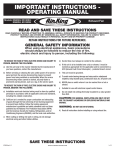
3.3 SENSOR WIRING & SPLICES.
WIRE SPLICE AND SEAL INSTRUCTIONS - 2 CONDUCTOR PAIRS KIT 10585-2
WARNING: USE CONNECTORS ONLY FOR THEIR DESIGNATED PURPOSE. DO NOT USE FOR AC WIRING.
1
2
BREAK APART
STRIP WIRES
FIELD CABLE *
(2) "V" SLOTS
1.25"
.75"
OUTER
SLEEVE
* PROBE FIELD CABLE SHIELD WIRE HAS NO CONNECTION
INNER
SLEEVE
2-WIRE SENSOR
OR MP46x PROBE
CABLE
USE TO SEAL 2-WIRE
SENSOR AND/OR MP46x
PROBE CABLE SPLICES
1.25"
.75"
SPLICE SEAL WIRE CONNECTOR PROVIDED BY PNEUMERCATOR
3
4
TWIST WIRES
INSERT
5
6
PULL ONE TWISTED LEAD PAIR
THROUGH EACH "V" AND BEND OVER
SNAP ON OUTER SLEEVE
DO NOT REUSE
PNEUMERCATOR
Bulletin 179 Rev. C (02/09/05)
Liquid Level Control Systems
Page 1 of 1
2/9/2005 5:33:57 PM, 1:1, © COPYRIGHT 2005 PNEUMERCATOR COMPANY, INC.
Figure 3-6 - 2-wire sensor Splice Kit Instructions
LC2000 Installation.doc
01-17-07
PAGE 20
INSTALLATION MANUAL
LC2000
WIRE SPLICE AND SEAL INSTRUCTIONS - 3 CONDUCTOR PAIRS KIT 10585-3
WARNING: USE CONNECTORS ONLY FOR THEIR DESIGNATED PURPOSE. DO NOT USE FOR AC WIRING.
1
2
BREAK APART
STRIP WIRES
1.25"
(3) "V" SLOTS
FIELD CABLE
.75"
OUTER
SLEEVE
INNER
SLEEVE
3-WIRE SENSOR
CABLE
USE TO SEAL 3-WIRE
SENSOR CABLE SPLICES
1.25"
.75"
SPLICE SEAL WIRE CONNECTOR PROVIDED BY PNEUMERCATOR
3
4
TWIST WIRES
INSERT
5
6
PULL ONE TWISTED LEAD PAIR
THROUGH EACH "V" AND BEND OVER
SNAP ON OUTER SLEEVE
DO NOT REUSE
PNEUMERCATOR
Bulletin 180 Rev. C (02/09/05)
Liquid Level Control Systems
Page 1 of 1
2/9/2005 5:40:55 PM, 1:1, © COPYRIGHT 2005 PNEUMERCATOR COMPANY, INC.
Figure 3-7 - 3-wire sensor Splice Kit Instructions
LC2000 Installation.doc
01-17-07
PAGE 21
INSTALLATION MANUAL
LC2000
IMPORTANT! LC2000 SENSOR WIRING INSTRUCTIONS
IDENTIFY THE TYPE OF SENSOR(S) TO BE INSTALLED. WIRING MUST BE TERMINATED ON THE
TERMINALS INDICATED BELOW TO ENSURE CORRECT OPERATION.
2-WIRE SENSORS
+V
SIG
HS100-ND
RED
LS600
M
O
D
E
L
BLK
NOTE: CONDUCTOR COLOR PAIR PER
SWITCH POINT. REFER TO THE TAG
ATTACHED TO THE SENSOR.
+V
2 SIG
LS610
RSU801
RSU800
(NON-DISCRIMINATING)
+V
SIG
GRN
BLK
2
W
I
R
I
N
G
+V
SIG
3-WIRE SENSORS
+V
SIG
RED
ES825-100 SERIES
ES825-200 SERIES
WHT OR GRN
BLK
+V
2 SIG
M
O
D
E
L
RED
HS100D
+V
SIG
BLK
WHT OR GRN
GRN
RED *
RSU800
(DISCRIMINATING)
BLK
+V
SIG
W
I
R
I
N
G
+V
SIG
+V
SIG
* RED IS COMMON GROUND WIRE
Questions? Contact Technical Support at (800) 209-7858
PNEUMERCATOR
Bulletin 204 No Change (01/17/07)
Liquid Level Control Systems
Page 1 of 1
Figure 3-8 - LC2000 sensor wiring
LC2000 Installation.doc
01-17-07
PAGE 22
INSTALLATION MANUAL
LC2000
3.4 PROGRAMMABLE RELAY OUTPUTS/CONTACT CLOSURE INPUTS
The LC2000 provides dry contact closure inputs and relay contact closure outputs that are
user-programmable via the console front panel or most LC communications interfaces. Each input
is programmable for relay control and alarm functions as well as remote relay acknowledgement or
gating functions. Each relay output is programmable to trigger on any combination of events,
including leak or point level sensor alarm, contact closure input or system error. Additionally, relays
are individually programmable for failsafe mode; delayed shutoff mode and a latching mode for
pump up/down functions. Typical relay applications include remote annunciation, pump and siphon
break/flow control valve operation, and other user-defined switch closure inputs. These relays also
provide a simple and straightforward interface to most programmable logic controllers, building
management systems, and similar input monitoring devices.
The standard LC2000 includes two (2) dry contact closure inputs and two (2) relay contact closure
outputs as illustrated in Figure 3-9 below. Also shown is an optional 4 Input/4 Relay Output Card.
An optional 8 Input/8 Relay Output Card or 16 Relay Output Card is available.
CAUTION
Relay output and contact closure input terminals are located on the
NON-INTRINSICALLY SAFE side of the console. ALL wiring to these terminals
MUST enter through the designated conduit opening. Refer to FIGURE 1-3.
FAILURE TO COMPLY MAY RESULT IN PERSONAL INJURY, PROPERTY LOSS
AND EQUIPMENT DAMAGE.
OPTIONAL RELAY
CARD
RELAY OUTPUTS
CONTACT
CLOSURE INPUTS
STANDARD
RELAY OUTPUTS
STANDARD CONTACT
CLOSURE INPUTS
DRAWING NO. 20051 REV. N/C
Figure 3-9 - Relay Output/Contact Closure Input Layout
(Optional 4 Relay Output/4 Contact Closure Input Expansion Card shown)
LC2000 Installation.doc
01-17-07
PAGE 23
INSTALLATION MANUAL
LC2000
3.5 DATA COMMUNICATIONS WIRING
The console's power area is equipped with three (3) communications ports that are assigned as
follows:
One (1) for external EIA RS-232 Interface to externally mounted computers or modems.
One (1) for external EIA RS-485 Interface to externally mounted PNEUMERCATOR smart
peripheral control devices.
One (1) for use with an optional communications expansion board.
Figure 3-10 shows the locations of these ports.
CAUTION
All communication terminations are located in the NON-INTRINSICALLY SAFE
side of the LC2000 console. ALL wiring to these terminals MUST enter the
designated conduit opening. Refer to FIGURE 1-3. FAILURE TO COMPLY MAY
RESULT IN PERSONAL INJURY, PROPERTY LOSS AND EQUIPMENT DAMAGE.
OPTIONAL
COMMUNICATIONS CARD
OPTIONAL
RELAY CARD
RS-232 CONNECTION
RS-485 CONNECTION
STANDARD
RELAY OUTPUTS
STANDARD CONTACT
CLOSURE INPUTS
DRAWING NO. 20075 REV. N/C
Figure 3-10 - Non-Hazardous Expansion Option Installation
LC2000 Installation.doc
01-17-07
PAGE 24
INSTALLATION MANUAL
LC2000
3.6 SENSOR MAP/SYSTEM SETUP
The sensor map/system setup below should be completed by the electrical installer as each sensor
and control output function is wired to the LC2000 system. This will provide the equipment operator
a means of identifying each field device for proper system setup programming and use. The
SENSOR MAP should be adhered to or kept near the LC2000 console.
SENSOR MAP/SYSTEM SETUP
CHNL
1
2
3
4
5
6
7
8
9
10
11
12
13
14
15
16
LEAK INPUT USAGE
SENSOR
CHNL
1
2
3
4
5
6
7
8
AUX/SWITCH INPUT USAGE
SENSOR
RELAY
1
2
3
4
5
6
7
8
9
10
11
12
13
14
15
16
17
18
ALARMS
USAGE
LC2000 Installation.doc
01-17-07
PAGE 25
LC2000 Installation.doc
PAGE 26
If Alarm
Sounds
Call:
DISPENSERS
1-4
DISPENSERS
5-8
DISPENSERS
9 - 12
DISPENSERS
13 - 16
LOW - T2
HIGH - T3
LOW - T3
HIGH - T4
LOW - T4
TYPE II INSERT WITH LABEL
INSTALL THRU SLOT AS SHOWN
(555) 501-0005
TYPE I INSERT WITH LABEL
INSTALL THRU SLOT AS SHOWN
FOR CHANNELS 1-8
INSIDE COVER VIEW
LEAK - T4
HIGH - T2
COMPANY ABC INC.
LEAK - T3
LOW - T1
TYPE I INSERT WITH LABEL
INSTALL THRU SLOT AS SHOWN
FOR CHANNELS 9-16
TYPE II
EMERGENCY
CONTACT
LABEL
EXAMPLE
TYPE I
ADVISORY LABEL
EXAMPLES
LEAK - T1
LEAK - T2
HIGH - T1
NOTE: 21-LABEL 8 1/2" X 11" SHEET WITH PRE-PRINTED
TYPE I AND II LABELS PROVIDED. USE TEMPLATE (ON CD
OR DOWNLOAD FROM www.pneumercator.com) TO FILL IN
AND PRINT ADVISORY AND EMERGENCY CONTACT
INFORMATION AS NEEDED. LABEL INFORMATION MAY
ALSO BE HAND WRITTEN.
TYPES I AND II INSERT LABELS - P/N 313262-1-21
TOP
TYPE II CARRIER INSERT - P/N 313245-1
P/N 313261-1 REV. N/C
TOP
TYPE I CARRIER INSERT - P/N 313261-1
DISPENSERS
9 - 12
DISPENSERS
13 - 16
P/N 313261-1 REV. N/C
HIGH - T4
LOW - T4
P/N 313261-1 REV. N/C
(555) 501-0005
DWG NO. 20074 REV. N/C
COMPANY ABC INC.
DISPENSERS
5-8
LOW - T3
If Alarm
Sounds
Call:
DISPENSERS
1-4
HIGH - T3
OUTSIDE COVER VIEW
TOP
LEAK - T3
LEAK - T4
LOW - T2
LOW - T1
HIGH - T2
LEAK - T1
LEAK - T2
HIGH - T1
TOP
TOP
INSTALL LABEL ON CARRIER INSERT
INSTALLATION MANUAL
LC2000
3.7 CARRIER INSERT INSTRUCTIONS
01-17-07
P/N 313245-1 REV. N/C
P/N 313245-1 REV. N/C
PNEUMERCATOR LC SERIES
LIMITED WARRANTY
LC Series
Pneumercator, here and after referred to as PCO, warrants its LC Series family of products to be free of defects in
material and workmanship for a period of Twelve (12) months from date of installation or Fifteen (15) months
from date of invoice, whichever comes first.
During the warranty period on the LC Series, PCO, or factory third party independent representatives will repair or
replace the product at the location where it is installed at no additional cost to the customer.
Packages must be inspected upon receipt for damage, missing parts, and/or manuals. PCO must be contacted by
telephone immediately with a description of damaged or missing parts so replacements can be sent. Written details
must be sent within thirty (30) days.
Pneumercator will not be responsible for shipping charges incurred by the customer.
Warranty repair coverage invoices will be paid if all the following conditions are met:
•
PCO has acknowledged and authorized warranty work to be done by issuing a Warranty Repair Number.
•
Start-up Service technician has been trained by PCO
•
Warranty start-up form has been submitted to PCO
•
Technician fills out and submits a PCO “Service Report”
•
Parts (if any) used are returned to PCO with a proper WRGA (Warranty Return Goods Authorization)
•
Returned parts are found to be defective.
Repair time will be paid according to PCO document “Standard Warranty Labor Charge Schedule”
If the Warranty Registration/Start up Check List has been completed and returned on file with the factory and the
product is installed in accordance with the specific PCO Installation Product Manual, PCO will activate and meet
warranty criteria as described above. Warranty criteria shall be voided if any product has been subjected to misuse,
negligence, damage from acts of nature (lightning, wind, rain, etc.) or is in violation of the products design intent,
disregard to warnings, instructions, modified or repaired by unauthorized personnel or improperly installed. Given
that the third party independent contractor has installed the equipment in accordance with the specific product
instruction manual, and followed all precautions, PCO will fulfill the terms stated in our warranty obligation.
Under no circumstances does the warranty provide a remedy in excess of the equipment. No other expressed or
implied warranty is given by PCO. PCO shall not be liable for consequential damages or any expenses incurred by
the user.
Distributed by:
PNEUMERCATOR
Liquid Level Control Systems
120 Finn Ct. Farmingdale NY 11735
(631) 293-8450 Fax (631) 293-8533