1
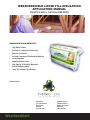
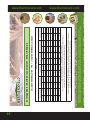
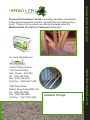
Eco-Friendly
Loose Fill Blown-in
Cellulose Insulation
Installation Manual
Weathershield is a loose-fill blown-in type 1 cellulose
insulation for ease of installation in attics, walls,
ceilings and floors.
Its not only a natural choice for the environmentally-conscious consumer but
one that outperforms both thermally and acoustically. With a superior R-value of
3.8 per inch, Weathershield’s excellent coverage, perfect fit and greater density
is a sound alternative to other fibrous insulations.
Weathershield insulation delivers long-term fire retardant protection and unlike
other insulation products, will not melt or propagate fire. Safe and easy to
install, it does not itch or contain any formaldehyde or harmful emissions. It is
specially treated to repel insects and rodents and will not promote the growth of
harmful mold and fungi.
With over 87% recycled content, and many performance benefits, Weathershield
is a natural choice for all your insulation needs. Start saving today, save on
product cost and get immediate rewards in energy savings.
Weathershield
provides seamless
coverage
Superior thermal
and acoustical
properties - comfort
www.thermocell.com
Weathershield Cellulose Insulation
Contact us today for more iinformation.
Weathershield is available in Ontario, Quebec and Atlantic Canada
Attic Requirements
1 bag per 36 ft2 (3.3m2)
1 bag per 22 ft2 (2.1m2)
1 bag per 18ft2 (1.7m2)
1 bag per 12ft2 (1.1m2)
Please carefully read manufacturer’s instructions and precautions prior to
application in order to ensure proper installation.
Weathershield is manufactured in accordance with CAN/ULC-S703-09
“Standard for Cellulose Fibre insulation for Buildings” and has been
evaluated by Canadian Construction Materials Centre (CCMC #08251-L).
Weathershield is manufactured under a certified quality management system. If
you consider all of the environmental advantages of Weathershield and combine
this with its performance, safety and cost effectiveness, cellulose is the right
choice ... naturally.
Increased Fire Resistance
Environmentally
Preferred 87% Recycled Content
www.thermocell.com
R-20 (RSI 3.5)
R-32 (RSI 5.6)
R-40 (RSI 7.0)
R-60 (RSI 10.6)
Easy & Safe to install
WEATHERSHIELD LOOSE FILL INSULATION
APPLICATION MANUAL
FOR ATTICS, WALLS, FLAT OR SLOPED ROOFS
ADVANTAGES AND BENEFITS:
•
•
•
•
•
•
•
•
•
High Stable R-Value
Controls air Leakage and Convection
Reduces Conduction
Prevents Formation of Condensation Moisture
Cooler Summers
Seamless Blanket Cover
High Density To Resist Air Movement
Sound Deadening Ability
Lasts The Lifetime of the Building
Manufactured By:
Head Office
Maritime Division
123 Clement Street1822 Plains Road
Vars, OntarioDebert, Nova Scotia
K0A 3H0B0M 1G0
(613) 443-5100(902) 662-3600
Weathershield
TABLE OF CONTENTS
Product Performance Specifications. . . . . . . . . . . . . . . . . . . . . . . . . . . . . . . . . . ..... . . . . . . . . . . . .1
Weathershield’s Features. . . . . . . . . . . . . . . . . . . . . . . . . . . . . . . . . . . . . . . . . . . . . . . . . . . . . . . . .1
Factors Effecting Heat Loss.. . . . . . . . . . . . . . . . . . . . . . . . . . . . . . . . . . . . . . . . . . . . . . . . . ... . . . .1
Infiltration. . . . . . . . . . . . . . . . . . . . . . . . . . . . . . . . . . . . . . . . . . . . . . . . . . . . . . . . . .... . .. .2
Convection. . . . . . . . . . . . . . . . . . . . . . . . . . . . . . . . . . . . . . . . . . . . . . . . . . . . . . . . . . . . . .2
Conduction.. . . . . . . . . . . . . . . . . . . . . . . . . . . . . . . . . . . . . . . . . . . . . . . . . . . . . . . . . .. . . .2
R-Value. . . . . . . . . . . . . . . . . . . . . . . . . . . . . . . . . . . . . . . . . . . . . . . . . . . . . . . . . . . . .. . . .3
Performance Value.. . . . . . . . . . . . . . . . . . . . . . . . . . . . . . . . . . . . . . . . . . . . . . . . . . . . . . .3
Planning Considerations. . . . . . . . . . . . . . . . . . . . . . . . . . . . . . . . . . . . . . . . . . . . . . . . . . . .... . . . . .3
Heat Sources. . . . . . . . . . . . . . . . . . . . . . . . . . . . . . . . . . . . . . . . . . . . . . . . . . . . .. . . . . . . .3
Air Ducts. . . . . . . . . . . . . . . . . . . . . . . . . . . . . . . . . . . . . . . . . . . . . . . . . . . . . . . . ... . . . . . .3
Exposure to Water. . . . . . . . . . . . . . . . . . . . . . . . . . . . . . . . . . . . . . . . . . . . . . . . .. . . . . . . .3
Masonry Wall Cavities.. . . . . . . . . . . . . . . . . . . . . . . . . . . . . . . . . . . . . . . . . . . . ... . . . . . . .4
Attic Ventilation/Insulation Stops/Air Chutes. . . . . . . . . . . . . . . . . . . . . . . . . . .... . . . . . . . .4
Moisture Diffusion.. . . . . . . . . . . . . . . . . . . . . . . . . . . . . . . . . . . . . . . . . . . . . . . . . ... . . . . .4
Dust Masks.. . . . . . . . . . . . . . . . . . . . . . . . . . . . . . . . . . . . . . . . . . . . . . . . . . . . . . . . . . . . .4
Bulkhead Openings. . . . . . . . . . . . . . . . . . . . . . . . . . . . . . . . . . . . . . . . . . . . . . . . . . . . . . .4
Existing Wall Cavity Insulation.. . . . . . . . . . . . . . . . . . . . . . . . . . . . . . . . . . . . . . ... . . . . . .4
Balloon Framing. . . . . . . . . . . . . . . . . . . . . . . . . . . . . . . . . . . . . . . . . . . . . . . . .. . . . . . . . .4
Drilling Access Holes. . . . . . . . . . . . . . . . . . . . . . . . . . . . . . . . . . . . . . . . . . . . . .. . . . . . . .4
Reversed Vapour Barrier. . . . . . . . . . . . . . . . . . . . . . . . . . . . . . . . . . . . . . . . . . . . . . ... . . .4
Poor Fit With Batts. . . . . . . . . . . . . . . . . . . . . . . . . . . . . . . . . . . . . . . . . . . . . . . . . . .. . . . .4
Attic Hatch.. . . . . . . . . . . . . . . . . . . . . . . . . . . . . . . . . . . . . . . . . . . . . . . . . . . . . . . . .. . . . .4
Recommended Equipment.. . . . . . . . . . . . . . . . . . . . . . . . . . . . . . . . . . . . . . . . . . . . . . . . . . .. . . . .5
Blowing Machines. . . . . . . . . . . . . . . . . . . . . . . . . . . . . . . . . . . . . . . . . . . . . . . . . . . . . . . .5
Low Volume Electric.. . . . . . . . . . . . . . . . . . . . . . . . . . . . . . . . . . . . . . . . .. . . . . . .5
High Volume Gasoline or Diesel.. . . . . . . . . . . . . . . . . . . . . . . . . . . . . . . . . . . . . .5
Accessories. . . . . . . . . . . . . . . . . . . . . . . . . . . . . . . . . . . . . . . . . . . . . . . . . . . . . . . . . . . . .5
Attic Application Procedures - Horizontal Ceiling. . . . . . . . . . . . . . . . . . . . . . . . . . . . . . ..... . . . . . .6
Air Adjustment.. . . . . . . . . . . . . . . . . . . . . . . . . . . . . . . . . . . . . . . . . . . . . . . . . . . . .. . . . . .5
Insulation Depth.. . . . . . . . . . . . . . . . . . . . . . . . . . . . . . . . . . . . . . . . . . . . . . . . . . . . . . . . .5
Perimeter Application. . . . . . . . . . . . . . . . . . . . . . . . . . . . . . . . . . . . . . . . . . . . . . .. . . . . . .6
Attic Application Procedures - Sloped Ceilings (4.5 in 12 pitch or less). . . . . . . . . . . . . . . . .... . . .6
Insulation Stops (Vents).. . . . . . . . . . . . . . . . . . . . . . . . . . . . . . . . . . . . . . . . . . . . . . . . . .6
Alternative for Perimeter Application. . . . . . . . . . . . . . . . . . . . . . . . . . . . . . . . . . . . . . .. . .6
Flat or Sloped Roof (enclosed cavity) Application. . . . . . . . . . . . . . . . . . . . . . . . . . . . . . . . . . ... . .6
House Trailers. . . . . . . . . . . . . . . . . . . . . . . . . . . . . . . . . . . . . . . . . . . . . . . . . . . . . . . . . .6
Flat or Sloped Roofs. . . . . . . . . . . . . . . . . . . . . . . . . . . . . . . . . . . . . . . . . . . . . . . . . . . .. .6
Weathershield
Floors. . . . . . . . . . . . . . . . . . . . . . . . . . . . . . . . . . . . . . . . . . . . . . . . . . . . . . . . . . . . . . . . .8
Hole Locations. . . . . . . . . . . . . . . . . . . . . . . . . . . . . . . . . . . . . . . . . . . . . . . . . . . . . . . . . .6
Drilling Access Holes. . . . . . . . . . . . . . . . . . . . . . . . . . . . . . . . . . . . . . . . . . . . . . . . . . . . .6
Install Insulation.. . . . . . . . . . . . . . . . . . . . . . . . . . . . . . . . . . . . . . . . . . . . . . . . . . . . . . . .7
Repairing Holes. . . . . . . . . . . . . . . . . . . . . . . . . . . . . . . . . . . . . . . . . . . . . . . . . . . . . . . . .7
Wall Installation Procedures - Retrofit. . . . . . . . . . . . . . . . . . . . . . . . . . . . . . . . . . . . . . . . . . ... . . .7
Removal of Siding. . . . . . . . . . . . . . . . . . . . . . . . . . . . . . . . . . . . . . . . . . . . . . . . . . . . . . .7
Fire Blocks. . . . . . . . . . . . . . . . . . . . . . . . . . . . . . . . . . . . . . . . . . . . . . . . . . . . . . . . . . . . .7
Cavity Completely Enclosed. . . . . . . . . . . . . . . . . . . . . . . . . . . . . . . . . . . . . . . . . . .. . . . .7
Air Setting. . . . . . . . . . . . . . . . . . . . . . . . . . . . . . . . . . . . . . . . . . . . . . . . . . . . . . . .. . . . . .7
Quantity Check. . . . . . . . . . . . . . . . . . . . . . . . . . . . . . . . . . . . . . . . . . . . . . . . . . . . . . . . .7
Direct Blow (two Hole) Method. . . . . . . . . . . . . . . . . . . . . . . . . . . . . . . . . . . . . . . . . . . .. .8
Injection Method. . . . . . . . . . . . . . . . . . . . . . . . . . . . . . . . . . . . . . . . . . . . . . . . . . . .. . . . .8
Wall Installation Procedures - New Construction. . . . . . . . . . . . . . . . . . . . . . . . . . . . . . . . . .... . . .8
ANNEX A - CAN/ULC-S703 (Standard for Cellulose Fibre Insulation for Buildings). . . ......... . . . .9
ANNEX B - Weather shield Coverage Chart ................................................................................10
ANNEX C - Product Warranty........................................................................................................11
Weathershield is manufactured in Canada
and is available coast to coast
Weathershield
Introduction
This manual is a general installation guide for Weathershield loose fill insulation in attics, flat or sloped
roofs, walls and floors.
Product Performance Specifications
Weathershield is manufactured in accordance with Underwriter Laboratories of Canada (ULC) Standard
CAN/ULC-S703-09. This standard contains several very demanding product performance requirements an abbreviated standard is included as an annex to this publication.
To ensure Weathershield is manufactured to these high standards, Weathershield is evaluated and listed
with the Canadian Construction Material Centre (CCMC). Also, Weathershield is manufactured under an
ISO 9001:2008 certified quality management system.
Weathershield’s Features
• High R-Value - as much as 35 percent better than conventional insulation.
• Perfect fit Requires no cutting or splitting.
Reduces heat losses due to air leaks around wires, pipes and fixtures.
No air leaks as commonly found with improperly fitting batts and at batt seams.
• High density As much as three times as dense as conventional insulation.
Reduces heat losses caused by air infiltrating directly through the insulation.
• Treated with borates to resist fire, pests, mould, mildew, rot and corrosion.
• Made with at least 85% recycled paper fibre.
Weathershield is an effective and economical insulation system designed to cut the rising costs for heating
and cooling. Remember, optimum product performance is obtained when the installation is done correctly.
The following procedures are only recommendations by the manufacturer. In the event these
recommendations appear inadequate, the applicator should consult the manufacturer for further information
and advice.
Factors Effecting Heat Loss
To help provide the general public with a means by which insulation performance can be measured and
compared, R-Value (Resistance-Value) was established. R-Value is derived from thermal conductivity
measurements which is a measure of the amount of heat energy which flows through a material over a
given period of time. Thermal conductivity measurement are made under non-extreme laboratory conditions
and does not describe the overall resistance of the material to heat loss.
Overall heat losses not only occur by conduction but by convection and infiltration. When all these factors
are taken into consideration a true picture of the insulation’s performance can be made and is commonly
referred to as P-Value.
1
Weathershield insulation offers a solution to this problem. It has been used successfully for many years in
schools, restaurants, hotels, swimming pools, arenas, warehouses and all types of farm and commercial
buildings. It is a short, fibrous and dense material which conforms to irregularities such as electrical boxes,
wiring and plumbing pipes, thus providing a seamless blanket of insulation. Conversely, batt insulation
leaves gaps and voids at butts, along studding and joists, next to sheathing and around any fixture such as
electrical boxes or pipes. According to independent studies these air leakage factors can cause the
effective R-Value to be reduced by up to 50%. Furthermore, such air movement into the wall and ceiling
membrane carries water vapour which can result in condensation problems. A comprehensive test for
P-Value concerns the four areas of performance discussed below. If an insulation performs well in each of
these areas, it will perform well in a structure, resulting in low heating costs.
Infiltration: This is the movement of warm or cold air from one area to another such as through walls,
around windows and doors, heat vents, plate lines, corners and any other area where air can move
through. Air infiltration can occur by passing directly through the insulation, by passing through defects in
construction such as gaps, cracks or voids. For good performance, it is essential to control air flow. For
many years vapour barriers were used in an attempt to control air flow. Even today this method is still being
used because of the very basic misconception that a vapour barrier is adequate to stop infiltration. It is now
known that vapour barriers do not stop infiltration, nor do exterior type barriers such as rigid foam
sheathing. Air leakage is best controlled by the insulation itself. If the insulation component leaks air,
infiltration and convection will result. Even if an infiltration barrier results in a tight house it will not necessarily be a warm house. Let us illustrate that by the example of a new house with no insulation. Having determined that infiltration was a major heat loser, let’s wrap the entire house with a poly barrier.
Would this house then be warm and comfortable? The answer to this question is no, as will be revealed
below under “convection”. Let’s consider the same house with the vapour barrier and a loosely bound
insulation fibre of full thickness in the wall and attic.
Would this house be warm and comfortable?
Answer: It would be better than the empty cavities, but even though the infiltration is cut out, convection
still exists. If we wanted this house to be very comfortable, we would use an insulation product that does
not allow free air flow. This would stop the infiltration and convection problem and create a very comfortable
house. Urethane and other foam type sub-sidings which are vapour barriers themselves, should never be
put on the outside of exterior walls. Exterior wall membranes should be able to breathe so that any moisture
which accumulates may dissipate by diffusion to the atmosphere. Although vapour barriers are a separate
subject, we are mentioning this so that you will understand that the very best method for restricting air flow
is to fill the wall and attic with a material that resists infiltration, and not rely completely on poly or sidings for
control.
Convection: Convection is the circulation of air within a space. Air when heated, rises, and when cooled,
falls. In a wall, natural forces of gravity along with warmer inner surfaces and colder outer surfaces create a
continuous movement of air which in turn facilitates the transfer of heat energy.
Conduction: is the transmission of energy moving through a substance. If a building material is conductive such
as the glass used in windows heat loss will occur directly across the material. Similarly building materials
with low thermal properties accelerates convective heat losses because the material facilitates a differential
temperature gradient between the warm and cold environments.
2
R-Value: This is the resistance of heat or the measure of heat lost through a material. This test is done in a
laboratory using a 5.5” thick sample, at a mean temperature of 75o F (24oC) with a temperature difference
across the sample of 72o F (22oC). R-Value then is testing heat flow through insulation or other materials.
Air flow is not part of the test.
Performance Value: Performance of insulation cannot be evaluated before each of the above factors
are evaluated individually. To determine the performance of an insulation, one must evaluate its ability to
control infiltration, convection and conduction. To sell high performing products, the customer will need to
understand the difference between high performing products and R-Value alone. Contractors and builders
especially need to understand these factors. If they are genuinely interested in quality of insulation, they
respond to this approach. If they accept the idea of Performance-Value (P-Value), they will be interested in
giving you future jobs. The basic reason for this performance is as follows:
a) Glass fibre batts installed in an exterior wall are dry, but because of air leakage the
glass fibre batt and surrounding construction materials are continuously subject to
moisture gains through condensation.
b) Weathershield remains dry on a continuous basis because of its resistance to air
leakage and air convection.
Planning Considerations
The following items should be given attention prior to installing insulation:
Heat Sources: Maintain building, electrical, gas and oil safety code clearances between the insulation and
heat emitting device, such as fuel burning appliances, chimney pipes, ducts and vents to these appliances
(at least 2” (50mm)) and recessed light fixtures (at least 3” (75mm)) unless approved for insulation contact.
Do not cover recessed light fixtures or other heat emitting devices that are not approved for insulation
contact with any type of insulation because the heat which is generated has no means of escape. The
resultant heat build-up may be enough to ignite surrounding combustible building materials. The consideration
also applies to other heat sources such as fan motors, transformers or especially, incandescent light bulbs
such as the one on the end of your trouble light cord. Never cover these items with insulation. Similarly, do
not permit insulation to directly contact a chimney or flue. Do not fill up chimney chases.
“NEVER CUT CORNERS WHEN DEALING WITH FIRE HAZARDS”.
Maximum Service Temperature: To preserve the integrity and performance of the insulation, constant ambient temperatures should not exceed 90oC (194o F).
Air Ducts: Combustion air intakes for fireplaces and furnaces must not be blocked and insulation should
not be installed in a manner which would allow it to be drawn into or cooling system. Particular attention
should be paid to any loose connection in duct work located in attic areas.
Exposure to Water: Recurring exposure to conditions such as rain, or running water must be avoided; as
this will reduce the thermal resistance of the insulation.
3
Masonry Wall Cavities: This insulation is not recommended for filling the cavities of masonry walls.
Attic Ventilation/Insulation Stops/Air Chutes: Attic ventilation is an important factor for good insulation
performance. It is recommended that 1 ft² (100cm2) of ventilation area be provided for each 300 ft² (3m2)
of ceiling area. It is recommended that 50% of ventilation space be located in the soffit area and the other
50% be on the roof or gable ends. Properly installed stops are also necessary to prevent wind coming
through the soffits blowing the insulation back from the eave area. Use air chutes for renovation work
because stops are difficult to install once the ceiling is in place. Insulation stops that are positioned between
the roof rafters to allow ventilation from soffits are available from our warehouse stock.
Moisture Diffusion: It is important that moisture be able to escape from within a building envelope.
Therefore, exterior sheathing material should be of the breathable type or, if not, have small spaces left
between sheets. When insulating flat roofs it is important diffusion points be provided around the perimeter.
Dust Masks: It is recommended that the installer wear a dust mask when installing the insulation in
confined areas. Although the product is non-toxic, like all nuisance dust it can be irritating to nasal passage
membranes.
Bulkhead Openings: Holes in ceilings or sidewalls that would allow the insulation to escape from the area
to be insulated should be sealed. In ceilings this could include openings into cabinet bulkheads, bulkheads
over bathtubs, and interior walls. In sidewalls, particular attention should be given to electrical box covers
and plumbing openings under sinks. Filling these areas would waste insulation and create a mess.
Bulkheads often contain recessed lights. Make sure the drywall or sheathing is securely fastened.
Existing Wall Cavity Insulation: Sidewalls should be checked for existing insulation. Weathershield
insulation can be easily pumped into empty wall cavities. Although under some conditions additional
insulation can be added to the cavity, it is recommended that the existing insulation be removed.
Balloon Framing: When blowing the walls on a two story house, determine if the wall section between
stories is open. If this is the case, some form of insulation stop is necessary in order to insulate this area
without wasting a lot of insulation in the joist spaces between floors.
Drilling Access Holes: Entry into wall cavities can be obtained by drilling a hole through the interior or
exterior wall surface, depending on wall conditions and preference.
Reversed Vapour Barrier: If you intend to add insulation to an attic which contains batt type insulation with
an impermeable facing on the top side you must completely break this facing so that a vapour barrier is not
formed in the middle of the insulation. Any applications of batts in this position were improperly made in the
beginning. (Facing should be on bottom side). Vapour barriers should always be located on the heated side
of a wall or ceiling. Also, the outside (cold side) of walls should be able to breathe so that moisture vapour
can escape. Many older homes and buildings don’t have a vapour barrier on the warm side of walls and
ceilings. The major source of moisture is air leakage. For good performance it is essential to control air
flow. Air leakage is controlled by the Weathershield itself. Weathershield’s short fibres, high density and the
seamless blanket cover provides high resistance to air leakage and prevents formation of condensation
moisture by preventing moist interior air from penetrating deep enough into the wall or ceiling insulation to
reach the dew point temperature. If a vapour barrier is desired, an oil base paint or a vapour barrier paint
applied to the drywall will serve this purpose.
4
Poor Fit With Batts: Glass fibre batt insulation is usually inserted between the ceiling joists from below,
and the installer or owner may not be aware of the areas where the batt is compressed or where poor fit
around obstructions or trusses leaves voids and gaps on the upper surface. These thin spots and gaps can
reduce the effective R-Value by up to 50%, and also cause moisture problems. Weathershield insulation
provides a seamless blanket cover that avoids these problems (P-Value).
Attic Hatch: A fence of backer board or plywood should be placed around the attic hatch to prevent the
insulation from falling out.
Recommended Equipment
Blowing Machines: A good variety of portable or truck mount, electric or internal combustion powered
machines are available:
Low Volume Electric: Agitator hopper (Krendl or equivalent) fitted with a fan type blower (Dumore
or Equivalent) and 100’ (30m) of 2½” (64mm) hose. This equipment is suitable for DIY attic
installation or low volume retrofit wall application. Production rates with this type of equipment is
usually around 800 lb/hr (360 kg/hr.).
High Volume Gasoline or Diesel: Large hopper, positive displacement blower (Vanco, Unimatic,
Heat Seal or equivalent) with a minimum 100’ of 3” (75mm) hose, or smaller if desired. This
equipment is recommended for high volume attic application but can also be used for wall
installation if air pressure is carefully reduced. Production rates with this type of equipment is
usually around 2000 to 2750 lb/hr (900 to 1250 kg/hr.). For wall installations use a 2” (50mm) hose
direct from the machine. Best performance on any installation, attic or wall, is achieved using a
minimum hose length of 150’ (45m).
Accessories:
1. Electric Drill (insulated) 1” (25mm) and/or 2c” (54mm) drill bit.
2. Plugs to fill access holes (plastic vented or paintable, wood or foam).
3. Appropriate finishing materials (mortar, joint filler, caulking, paint).
4. Dust masks, ladder, tape measure, plumb bob, hammer, etc.
Attic Application Procedures - Horizontal Ceiling
Air Adjustment: Set the air adjustment on the blowing machine as per manufacturer’s guide. The setting
will vary with the amount of hose you are using. The material should flow steadily (as water from a hose)
without creating excessive dust.
Insulation Depth: By holding the end of the hose in a horizontal to slightly inclined position and within a
few feet of the attic floor, apply the insulation. Install the insulation to the applied thickness which
corresponds to the desired R-Value located on the back of the package. Install the insulation as uniformly
as possible and ensure the correct number of bags (as determined by the coverage chart on the package)
are installed.
5
Perimeter Application: Inaccessible outer edges of an attic might be reached more easily if a rigid tube
extension, such as a lightweight aluminum or plastic pipe is attached to the end of the flexible hose.
Attic Application Procedures - Sloped Ceilings (4.5 in 12 pitch or less)
a) The same procedure for attic application on a horizontal ceiling would apply.
b) Insulation Stops (Vents): Make sure the insulation stop will extend inward a minimum of 6” above the
top surface of the insulation material to prevent blow back of material during windy conditions (The
minimum stop length should be 48” or 1200mm).
c) Alternative for Perimeter Application: Install insulation stops and then install glass fibre batts to cover
a 4’ (1200mm) strip around the perimeter. Then insulate down to the glass fibre batt.
NOTE: For slopes greater than 4.5 in 12, spaces must be enclosed (ventilation provided where possible)
and filled under pressure to achieve a finished density of 2.5 lb./ft3 (40.5 g/m3).
Flat or Sloped Roof (enclosed cavity) Application
House Trailers: House trailers are the most common example of flat roof construction. As no standard construction practices are employed, it is therefore necessary to check construction parameters before insulating. Ceiling panelling may be rather flimsy so very careful air control is required.
Flat or Sloped Roofs: The actual vertical thickness of ceiling joists determines the maximum possible
thickness of insulation.
Most flat roof construction includes some type of bridging between joists for added stability to the roof assembly. Such bridgings may obstruct the application tube, making it impossible to completely fill the joist
space from one side of the building, it is then necessary to complete the space from the other side of the
building or from inside using a directional nozzle.
For sloped ceilings (cathedral ceilings) greater than 4.5 in 12, spaces must be filled under pressure to
achieve a minimum density of 2.5 lb./ft3 (40.5 kg/m3) in order to prevent settlement.
Floors: Enclosed floor cavities may be filled in the same manner as a flat roof.
Hole Locations: Check roof assembly parameters (as mentioned above) and determine how many access
holes should be drilled and where. Should there be joist bridging within the roof assembly, both sides of
the building must then be marked for access holes. Provided there are no obstructions, at least one hole is
needed for each 10’ (3m) length of cavity space.
Drilling Access Holes: Since the application tube has a 2” (50mm)O.D., it is recommended that 2c”
(54mm) holes be drilled for access. Be sure to use the proper bit for the job.
Before drilling, it must be realized that upon completion of the job, you must repair the surface that has
6
been drilled. For trailers, aluminum sheathing usually can be removed and then replaced after insulating
(i.e. no need to refinish surface). For non-removable surfaces, it is important to realize that it is extremely
difficult to match the old surface (especially faded paint, stucco, siding, and other finishes).
Install Insulation: Beginning at one end of the roof assembly, insert application tube through access hole
into framing space. Endeavour to maintain a central position. Since you are working from back to front in
filling the cavity, insert application tube to near maximum in depth. Begin insulating. Progressively withdraw
the hose as each portion of the cavity is insulated. If thru-blower type insulating machine is used there will
be an audible increase in RPM of the fan blower motor as the hose blocks or flow stoppage is visible in
hose itself. Continue application until cavity has been completely filled.
Repairing Holes: Plug access holes and repair surfaces as required. Plastic vent plugs can be used.
Make sure the roof can breathe so that moisture can escape.
Wall Installation Procedures - Retrofit
Removal of Siding: Remove exterior finish material whenever possible before drilling holes as this will
eliminate patching.
Fire Blocks: Wall cavities should be checked for fire blocks or other obstructions by inserting an electrician’s fish
tape or plumb bob through the drilled holes.
Cavity Completely Enclosed: Unless the cavity is completely enclosed, it may not be possible to install
Weathershield under sufficient pressure to ensure complete fill and uniform density. Weathershield will not
settle if blown into the wall cavity at a minimum density of 3.0 lb/ft3 (48kg/m3).
Air Setting: The air setting for proper cavity fill is critical. Not enough air may result in light density and
possible voids. On the other hand too much air (with positive displacement blowers) could bulge or dislodge
panelling. Best to start with too little air and adjust upwards to the correct setting.
Quantity Check: Complete fill of the cavity can be double checked by doing a mathematical calculation
based on the amount of material installed and the volume of the stud spaces (see coverage chart on the
Weathershield package).
Direct Blow (two Hole) Method: This method is accomplished by filling the wall cavity from two points for
each eight feet of vertical wall section. Location of the 1” (25mm) or should be approximately two feet up
from the bottom and one foot down from the top. Only one hole is necessary above and beneath windows
and doors without solid headers. A 1” (25mm) or 2” (50mm) nozzle is available. For quicker installation, use
the 2” (50mm) nozzle and 2c” (54mm) hole. A special 2” (50mm) directional nozzle can be used to direct
Weathershield upward or downward more easily. You may prefer to use a 2c” (54mm) hole on the bottom
for high volume and a 1” (25mm) hole at the top where less material is required. Insert the nozzle into the
bottom hole first and blow until the material flow stops.
Next insert the nozzle into the top hole and continue the blow until the material flow stops, thus ensuring
the cavity is full. Excess air will find its way out through cracks and openings. To ensure complete fill under
electrical plug-in boxes, it is helpful to place the bottom hole slightly below the box level. Older houses
7
slated for interior refinishing may have the fill holes drilled on the inside. In the event you drill into electrical
wires, an electrician’s assistance should be obtained to assess and/or repair any damage. It is also advised
to use an insulated drill to avoid the possibility of electrical shock.
Injection Method: This method is accomplished by inserting a 1” (25mm) to 1 ½” (38mm) plastic hose
through a hole into the wall cavity. Insulation is blown into the cavity to the proper density by withdrawing
the hose in one foot stages each time the material stops flowing. To ensure that the hose is inserted into
the wall cavity properly, a piece of tape should be wrapped around the hose back from the end at a point
equal to the distance from hole to the top of the wall cavity. The end of the hose should be cut at an angle
to make passing obstructions easier.
These possibilities include entry from:
a) The outside wall behind or through the siding
b) The bottom plate
c) The inside wall behind the baseboard
d) The inside wall at the drywall tape joint.
When entering the wall cavity from points (a) and (c), the hole should be drilled at an upward angle.
Plugging the holes in the wall can be done with plastic plugs (paintable), wood or foam plugs. Plastic plugs
are typically used in areas where the plug will be concealed such as wood-lap, fibreboard, aluminum, vinyl
and steel siding. The tapered wood plugs can be used with wood lap, plywood, fibreboard and drywall.
Foam plugs are used exclusively as a backer on the interior walls for patching plaster. When using plugs
and doing hole repair, be careful not to guarantee colour of hole repair with the existing exterior finish which
could be difficult or impossible to blend.
Wall Installation Procedures - New Construction
Application of Weathershield in walls of new construction is currently limited to factory certified applicators
or individuals installing under the direct supervision of a certified applicator. Installation instructions and
guidelines are covered under the EnviroShield Insulation System. Please contact Thermo-Cell for
additional information.
8
ANNEX A
CAN/ULC-S703-09
Standard for Cellulose Fibre Insulation for Buildings
Underwriter’s Laboratories of Canada (ULC) is a private agency which certified by Standards Council of
Canada to produce product standards in a wide range of subject areas and have, in cooperation with
testing agencies, consumer groups and manufacturers, produced the above product standard for Cellulose
Fibre insulation. The current document supersedes CGSB 51.60 and came into effect in June 2000. CAN/
ULC-S703-09 requires that Weathershield meet or exceed the following test criteria:
Surface Burning Characteristics: Flame spread clarification shall not exceed 25 when tested in
accordance with CAN/ULC-S102M or 150 when tested in accordance with CAN/ULC-S102.2M.
Open Flammability: The critical radiant flux shall be greater or equal to 0.12 W/cm2.
Thermal Resistance: Thermal resistivity shall not be less than an R 3.3 (RSI of 18.5) nor less than the
values shown on the bag.
Density: Density shall be within plus/minus 10% of value used to establish coverage shown on bag).
Flame Spread Permanency: The critical radiant flux shall be greater or equal to 0.12 W/cm2. after the
aging process.
Moisture Vapour Sorption: Moisture gain after exposure to high humidity shall be no more than 20%
higher than the value determined before exposure.
Corrosiveness: Aluminum, copper, steel and galvanized steel samples shall not show pitting and/or weight
loss as stipulated in the Standard after 28 days exposure.
Fungi Resistance: Test specimen shall exhibit no more growth than the comparative item.
Separation of Chemicals: Separation during prescribed test shall not exceed 1.5% by mass of the sample.
Smoulder Resistance: Specimens shall not exhibit any flaming combustion and shall not exhibit a mass
loss greater than 15%.
NOTE: Actual test procedures for the above performance criteria are very detailed, and are available from
Thermo-Cell upon request.
9
10
Applied Thickness
Épaisseur Appliquée
mm
in (po)
90
3.5
150
5.9
210
8.3
240
9.4
262
10.3
270
10.6
299
11.8
374
14.7
412
16.2
449
17.7
kg/m2
2.06
3.43
4.80
5.48
6.00
6.17
6.85
8.57
9.42
10.28
lb/ft2 (lbs/pi2)
0.42
0.70
0.98
1.12
1.23
1.26
1.40
1.75
1.93
2.11
Mass per Unit Area
Masse par Unité de Surface
ATTICS / ENTRETOIT
Settled Thickness
Épaisseur Tassée
mm
in(po)
80
3.2
134
5.3
187
7.4
214
8.4
234
9.2
241
9.5
267
10.5
334
13.2
368
14.5
401
15.8
m2
5.5
3.3
2.4
2.1
1.9
1.8
1.7
1.3
1.2
1.1
ft2 (pi2)
59.4
35.6
25.4
22.3
20.4
19.8
17.8
14.3
13.0
11.9
Coverage per Bag
Recouvrement par Sac
# Bags Required
Quantité de Sacs Requis
1000 ft2 (pi2)
100 m2
18.1
16.8
30.2
28.1
42.3
39.3
48.3
44.9
52.9
49.1
54.4
50.5
60.4
56.1
75.5
70.2
83.1
77.2
90.6
84.2
Weathershield is manufactured under a certified quality management system. If you consider all of the environmental advantages
of Weathershield insulation and combine this with its performance, safety and cost effectiveness, cellulose is the right choice ... naturally.
R-VALUE 3.8/in (RSI 0.0263/mm)
DESIGN DENSITY 1.6 lbs/ft3 (25.6 kg/m3)
These charts represent average machine applied coverages which may be affected according to equipment and applicators' techniques.
From R-40 or RSI-7.0, it may be necessary to bring a correction according to the application technique.
3
3
COEFFICIENT R 3.8/po (RSI 0.0263/mm)
MASSE VOLUMIQUE THÉORIQUE 1.6 lbs/pi (25.6 kg/m )
Ces tableaux représentent des moyennes lorsque appliquées à la machine, la couverture varie selon l'équipement et les techniques de l'applicateur.
À partir de R-40 ou de RSI-7,0, il peut être nécessaire d'apporter une correction selon la technique d'application.
Thermal Resistance
Résistance Thermique
RSI Value
R Value
12
2.1
20
3.5
28
4.9
32
5.6
35
6.2
36
6.3
40
7.0
50
8.8
55
9.7
60
10.6
CELLULOSE FIBRE INSULATION TYPE 1 L'ISOLATION EN FIBRE CELLULOSIQUE
Coverage Chart / Charte de recouvrement - Attics / Entretoit
CCMC #08251-L
Masterformat #07212
www.thermocell.com
www.thermocell.com
- Manufacturer’s Warranty Thermo-Cell Industries Limited warrants that Weathershield Insulation is manufactured
to meets or exceed CAN/ULC-S703-09 (formerly CGSB 51.60-M90).
Weathershield Insulation is guaranteed in accordance with the installation record for the
normal life of the building, provided the material is installed according to manufacturers
instructions. The liability of Thermo-Cell will be limited to the replacement of defective
insulation or installation of additional insulation provided a copy of the product’s attic
completed card and proof of purchase is supplied to Thermo-Cell.
In no event shall Thermo-Cell be responsible or liable for any damages arising from the
improper installation or use of defective material whether such damages be direct, indirect, consequential or otherwise. This warranty excludes all damages to the insulation
resulting from defects or deterioration in the structure, physical or mechanical abuse
and/or acts of nature.
11
www.thermocell.com
Thermo-Cell Industries Limited is a leading Canadian manufacturer
of thermal and acoustical insulation, specialty fibres and hydroseeding
mulch. Thermo-Cell’s products are actively marketed under the
Weathershield, Pro-Cell and Celumulch trademarks.
For more information on:
1822 Plains Road
Debert, Nova Scotia B0M 1G0
Tel: (902) 662-3600
Fax: (902) 662-2882
Toll Free: 1 (877) 575-3600
Available through:
www.thermocell.com
contact Thermo-Cell at:
123 Clement Street
Vars, Ontario K0A 3H0
Tel: (613) 443-5100
Fax: (613) 443-5160
Toll Free: 1 (800) 267-1433