1
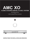
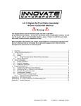
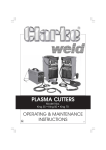
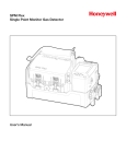
INSTRUCTION AND
INSTALLATION MANUAL
EC-F2 SENSOR FOR
AMMONIA
Model EC-F2-NH3
11511 West 83rd Terrace
Lenexa, Kansas 66214
ph. 913.894.1185
fax 913.894.1296
CONTENTS
Section
1
2
3
4
1
A
Title
Sensor Description
Installation
Operation
Warranty
Serial Number
SENSOR DESCRIPTION
Introduction
This manual has been prepared to
help in the use and installation of the
Manning Systems’ Model EC-F2-NH3
(Electrochemical-Ammonia) Sensor. This
manual will convey the operating principles of the sensor, ensure proper installation, and demonstrate start-up and routine maintenance procedures for the sensor.
This manual must be carefully followed by all individuals who have or
will have the responsibility for using or
servicing the sensor. Warranties made
by Manning Systems, Inc. with respect to
this equipment will be voided if the equipment is not used and serviced in accordance with the instructions in this manual.
If in doubt about a procedure, please
contact Manning Systems, Inc. before
proceeding.
B
Page
2
3
5
7
System Description
The Manning Systems’ EC-F2 Sensor is a three-wire, 4/20 mA sensor for
ammonia available in ranges of 0-100
ppm, 0-200 ppm, 0-250 ppm, 0-500 ppm,
and 0-1,000 ppm.
The unit exhibits excellent accuracy
and precision, with negligible response to
common interference gases and dramatic
changes in relative humidity. Reliable
trip levels as low as 25 ppm can be expected with the 0-100 ppm sensor. The
unit exhibits extremely high reliability
with no moving parts.
Monitoring equipment must be configured to indicate a fault if the signal is
less than 1.5 mA. All signals over 20 mA
must be considered a high gas concentration.
Specifications:
Method: Electrochemical (diffusion).
Ranges:
0-100 ppm (standard)
0-200 ppm
0-250 ppm
0-500 ppm
0-1,000 ppm
Output: Isolated 4/20 mA, 700 ohms
max at 24 VDC.
Accuracy: +/- 5% generally, but limited by available calibration gas accuracy.
2
MANNING EC-F2-NH3 SENSOR
Repeatability: +/-2% full scale.
Operating Humidity: 5-100% RH
(condensing). ATMOSTM enviro-adaptive technology option required for condensing conditions or refrigerated areas.
o
Operating Temperatures: -50 F
o
to 120 F. ATMOSTM enviro-adaptive
technology option required for refrigerated areas or outdoors.
Sensor Pressure Limits: 0-10 PSIG.
Power Source: 24 VDC, 0.5 amp
max.
Gas Sampling: Diffusion method is
standard (sample draw connections are
available).
Weight: 3 lbs.
Dimensions: 6” high x 4” wide x
3.5” deep.
Cable Recommendations: #18/3
shielded cable (Belden #8770 or equal),
cable runs <1,500 feet.
Enclosure: NEMA 1, gasketed, #16gauge steel (standard). NEMA 4, stainless steel or explosion-proof designs, including modified enclosures for low temperatures, ventilation ducts, etc., are available (contact Manning Systems). Note:
The standard EC is for use in non-classified areas only.
301-0304-h
2
A
INSTALLATION
Locating the EC-F2
Sensor
Because each sensor is a point measurement, it is very important that the
sensor be located properly.
One of the most important considerations when installing EC sensors is that
they must be easily accessible for calibration and maintenance. As a general rule,
locate sensors no closer than 1 foot from
the ceiling.
If the primary application is personnel protection (representative concentration reading that an employee would be
exposed to), mount the sensor at a height
in the breathing zone of the employees. It
would typically be about five feet off the
ground, which also allows easy access.
If the primary application is the fastest possible leak detection, mount the
sensor near the potential leak sources. In
the case of ammonia, this is usually near
the ceiling as ammonia vapor is lighter
than air. In doing this, be aware that the
indicated concentration will not be representative of personnel exposure and easy
access for the required calibration and
maintenance could be compromised.
No matter where the sensor is
mounted, it must be easily accessible.
General Mounting Considerations:
• Must be easily accessible for calibration and maintenance.
• Always mount the sensor vertically.
• Mount the sensor close to the potential leak source.
• If personnel protection is the primary application, mount in the “breathing
zone.”
• Protect sensor from water, excessive humidity, and wash-down.
• Take air movement and ventilation
patterns into account.
• To prevent electrical interference,
keep sensor and wire runs away from
mercury vapor lights, variable speed
drives, and radio repeaters.
• Protect sensor from physical damage (fork lifts, etc.).
• Do not mount the sensor over a
door in a refrigerated area.
• If mounting sensor outdoors, consider prevailing wind direction and proximity to the most likely source of leaks.
Protect the sensor from sun and rain as
much as possible.
• Never mount the sensor in CA (controlled atmosphere) rooms because normal atmospheric levels of oxygen are
required for operation.
• For highly critical locations more
than one sensor should be installed in
each room.
Blast freezers: Never mount sensor
above the coil. The ideal location, when
possible, is below the bottom of the coil.
Try to put in return air and protect the unit
from being damaged by product loading
and unloading. Keep it away from warm,
moist air during defrost. Usually four or
five feet off the ground is the best location.
Penthouses: Multi-Coil (defrost one
coil at a time): In this case the best
location is usually in the center of the
penthouse four or five feet above the
grate.
Single Coil (or when all coils defrost
at the same time): In this case high moisture conditions can occur and the sensor
should be mounted one foot above the
grate.
Engine Rooms: The EC sensor
should be mounted in a cool part of the
room, if possible. Keep the sensor away
from hot air exhausting from electric
motors or other machinery. Usually the
best location is four or five feet above the
floor in a location where the room exhaust
fan will move air across the sensor from
the potential leak source.
Ceiling Hung Evaporators: When
mounting EC sensors near evaporators,
mount the sensor no higher than two feet
below the top of the evaporator coil. DO
NOT mount in high air flow (1,200 feet/
minute maximum). Never mount the sensor on evaporators as vibration can damage the sensor.
Other Locations: When mounting
EC sensors in locations such as roof top
air units, duct-work, attic spaces, makeup
air intakes, etc., contact Manning Systems for application assistance and recommendations.
Sensor must be mounted vertically
Never mount flat on a ceiling
Enter enclosure only through existing hole in bottom
Always make a drip loop in the
conduit
Figure 1: Mounting dimensions for the EC-F2 Sensor
3
MANNING EC-F2-NH3 SENSOR
301-0304-h
2
B
INSTALLATION (CONT’D)
Wiring
Figure 2 presents wiring information
for the EC-F2 sensor.
Electrical wiring must comply with
all applicable codes. Plant equipment
that may be involved and operating conditions should be discussed with local
operating personnel to determine if any
special needs should be taken into account.
Almost all start-up problems are due
to improper wiring or monitor configuration. Please follow these guidelines carefully.
Always use three conductor, insulated, stranded, shielded copper cable.
Use only three conductor cable, not two
cables of two conductor wire.
Do not pull sensor wiring with AC
power cables. This will cause electrical
interference. Be sure there are no breaks
or splices in sensor wiring runs. If cable
runs cannot be made without a splice, all
connections must be soldered. Soldering
should be done using a rosin flux to tie the
connecting ends of sensor wires to ensure
a positive and long-lasting contact.
Ground the shield at the main control
panel. Connect the shield wire in the
sensor terminal block labeled SHLD.
Tape all exposed shield wire at the sensor
to insulate it from the enclosure.
All penetrations into a refrigerated
room should be sealed to prevent condensate from forming in the conduit and dripping into the sensor enclosure. Silicone
should not be used near the sensor, because silicone can damage the sensor.
Make drip loops for cables going into
sensor housings. When heated enclosures are used, follow the special mounting instructions on the enclosure (This
End Up).
Mount sensor enclosures through the
flange holes as shown in Figure 1, and
always mount vertically.
Electrical Power: 24 VDC regulated, 30 mA. With an ATMOSTM enclosure the current draw is 500 mA max.
Output: Circuit board mounted sensor provides a linear 4/20 mA output.
Monitoring equipment may have a maximum input impedance of 250 ohms.
Cable Recommendation: No. 18/3
shielded cable (Belden #8770 or equivalent). Length of cable to sensor should be
no greater than 1,500 feet. Use only the
existing punched holes for connections to
the sensor.
Monitoring: The EC-F2 Ammonia
Sensor may be monitored by the Manning
Systems’ Model 20, GM-1, GM-JR, GM10, or other appropriately configured system. Monitoring equipment must be configured to indicate a fault if the signal is
below 1.5 mA. All signals over 20 mA
must be considered a high gas concentration.
Connects to signal input of monitoring equipment
Connects to 24 VDC power supply positive side (40500 mA depending on environment)
Connects to 24 VDC ground side
Connects to case ground of monitoring equipment (earth ground)
Figure 2: Wiring diagram for the EC-F2 Sensor
4
MANNING EC-F2-NH3 SENSOR
301-0304-h
3
A
OPERATION
Start-Up Procedures
Before applying power, make a final
check of all wiring for continuity, shorts,
grounds, etc. (see Figure 3, Note 5) It is
usually best to disconnect external alarms
and other equipment from the sensor until
the initial start-up procedures are completed.
After power-up, allow 24 hours for
the system to stabilize before testing the
sensors. Because sensors are normally
located at a distance from the main unit,
the test time required and accuracy of the
response checks will be improved if two
people perform the start-up procedures
and use radio contact.
Start-Up Test:
1) One person exposes each sensor
to a small amount of the gas that is being
monitored.
2) The second person stays at the
control unit to determine that each sensor,
when exposed to the gas fumes, is connected to the proper input and responds,
causing appropriate alarm functions.
B
Zero Calibration: After the unit is
installed and has been powered up for a
minimum of 24 hours, the unit should be
zero calibrated by the following:
• Be sure the unit is in clean air.
• Adjust the zero pot until the sensor
outputs 40 mV from Test [-] to Test [+]
(see Figure 3, Note 2 and 4).
Span Calibration: The unit is factory calibrated and normally does not
need to be spanned upon initial installation. DO NOT ADJUST THE SPAN POT WITHOUT
CERTIFIED CALIBRATION GAS! If span adjust-
ment is required, the following procedure
will span the unit:
• Perform zero adjustment before
spanning.
• Apply span gas at 0.8 L/min (span
gas must be in air, not nitrogen or other
carrier).
• After span gas has been on sensor
for two minutes, adjust the span pot until
the correct output is achieved (see Figure
3, Note 1).
Calibration kits are available from
Manning Systems.
Note 1: Span Adjustment
Note 2: Zero Adjustment
Note 5: Sensor cable plugs in
here. Verify that sensor is plugged
in properly and cable is secured
Calibration
The EC-F2 Sensor comes factory calibrated and should require minimal adjustments after installation. There are two
pots on the preamp that are used for calibrations.
Note 4: Sensor Output
Note 3: Power Supply Voltage
Figure 3: Checking sensor output, power supply voltage, and zero
and span adjustments to the EC-F2 Sensor
5
MANNING EC-F2-NH3 SENSOR
301-0304-h
3
C
OPERATION (CONT’D)
Troubleshooting
If the sensor output is 0 mA: First,
verify +24 VDC at the sensor terminal
block (see Figure 3, Note 3).
Second, check voltage between Test
(-) and Test (+) (see Figure 3, Note 4).
Voltage should be in the range of 40 mV
to 200 mV corresponding to an actual
current flow of 4 to 20 mA. If this voltage
is 0 mV, the signal has no path to ground.
Check monitoring equipment connections
and configuration. Input impedance must
be 250 ohms or less.
Electrical Interference: This sensor has been designed to be highly resistant to EMI/RFI using multiple stages of
filtering and protection. However, in
extreme environments, some noise pickup
can occur directly through the sensor.
Ensure that the bare shield wire of the
instrument cable is connected to the terminal block marked SHLD at the sensor
(not touching the metal enclosure) and
properly grounded at the readout unit.
Interference Gases: The EC-F2NH3 is designed to be quite specific to
ammonia. However, some other gases
can affect the reading. Phosphene, methyl
mercaptan, and hydrogen can give a slight
upscale indication. Bromine, ozone, fluorine, chlorine, and nitrogen dioxide can
give a slight down-scale indication. Contact Manning Systems if any of these
gases are present in your application.
D
Maintenance
For proper operation it is essential
that the test and calibration schedule be
adhered to. Manning Systems recommends the following maintenance schedule:
• Calibration should be performed
with certified calibration gas every six
months or after major exposure to a leak.
Calibration kits are available from Manning Systems.
• Response test once between calibrations, i.e. at three month intervals. Expose sensor to ammonia/water solution to
verify proper sensor response and alarm
functions. Test more frequently in highly
critical applications. The response test is
not required if multiple electrochemical
sensors are installed in the same room.
• All tests and calibrations must be
logged.
Sensor Life: These electrochemical
cells are extremely reliable, but several
things can cause the cell chemicals to
become depleted including:
• a period of time,
• exposure to high temperatures,
• exposure to varying concentrations
of the target gas,
• exposure to high moisture for
extended periods without proper
sensor enclosure.
When the cell becomes depleted, the unit
will give no indication of failure other
6
MANNING EC-F2-NH3 SENSOR
than that the sensor will not respond. For
this reason it is absolutely essential that
these units be exercised with a gas
sample on a regular and timely basis.
Typical sensor life in a refrigerated
area will be three to four years. Typical
life in a non-refrigerated area will be one
and a half to two years. Exposure to high
levels of ammonia will shorten these times.
In addition to timely response checks, a
preventative maintenance program of periodic cell replacement should be implemented.
When the cell becomes depleted, a
replacement cell can be obtained from
Manning Systems. Simply unplug the
ribbon cable from the pins labeled Sensor, pull the old cell from the spring clip,
discard the old cell and replace it with a
new one.
The sensor should be calibrated after
a 24 hour warm-up period.
E
Replacement Parts
For replacement parts, contact Manning Systems. Be sure to give serial
number of unit and model number.
301-0304-h
4
WARRANTY
Limited Warranty
1. Limited Warranty. Manning Systems, Inc. (“Manning”) warrants to the
original purchaser and/or ultimate customer (“Purchaser”) of Manning’s Products (“Product”) that if any part thereof
proves to be defective in material or workmanship within eighteen (18) months of
the date of shipment by Manning or twelve
(12) months from the date of first use by
the purchaser, whichever comes first, such
defective part will be repaired or replaced,
free of charge, at Manning’s discretion if
shipped prepaid to Manning at 11511 W.
83rd Terrace, Lenexa, Kansas 66214, in a
package equal to or in the original container. The Product will be returned freight
prepaid and repaired or replaced if it is
determined by Manning that the part failed
due to defective materials or workmanship. The repair or replacement of any
such defective part shall be Manning’s
sole and exclusive responsibility and liability under this limited warranty.
2.
Exclusions.
A. If gas sensors are part of the
Product, the gas sensor is covered by a
twelve (12) month limited warranty of the
manufacturer.
B. If gas sensors are covered by this
limited warranty, the gas sensor is subject
to inspection by Manning for extended
exposure to excessive gas concentrations
if a claim by the Purchaser is made under
this limited warranty. Should such inspection indicate that the gas sensor has
been expended rather than failed prematurely, this limited warranty shall not apply to the Product.
C. This limited warranty does not
cover consumable items, such as batteries, or items subject to wear or periodic
replacement, including lamps, fuses,
valves, vanes, sensor elements, cartridges,
or filter elements.
3. Warranty Limitation and Exclusion. Manning will have no further obligation under this limited warranty. All
warranty obligations of Manning are extinguishable if the Product has been subject to abuse, misuse, negligence, or accident or if the Purchaser fails to perform
any of the duties set forth in this limited
warranty or if the Product has not been
operated in accordance with instructions,
or if the Product serial number has been
removed or altered.
4. Disclaimer of Unstated Warranties. THE WARRANTY PRINTED
ABOVE IS THE ONLY WARRANTY
APPLICABLE TO THIS PURCHASE.
ALL OTHER WARRANTIES, EX-
7
MANNING EC-F2-NH3 SENSOR
PRESS OR IMPLIED, INCLUDING,
BUT NOT LIMITED TO, THE IMPLIED
WARRANTIES OF MERCHANTABILITY OR FITNESS FOR A PARTICULAR PURPOSE ARE HEREBY DISCLAIMED.
5. Limitation of Liability. IT IS UNDERSTOOD AND AGREED THAT
MANNING’S LIABILITY, WHETHER
IN CONTRACT, IN TORT, UNDER
ANY WARRANTY, IN NEGLIGENCE
OR OTHERWISE SHALL NOT EXCEED THE AMOUNT OF THE PURCHASE PRICE PAID BY THE PURCHASER FOR THE PRODUCT AND
UNDER NO CIRCUMSTANCES
SHALL MANNING BE LIABLE FOR
SPECIAL, INDIRECT, OR CONSEQUENTIAL DAMAGES. THE PRICE
STATED FOR THE PRODUCT IS A
CONSIDERATION
LIMITING
MANNING’S LIABILITY. NO ACTION, REGARDLESS OF FORM, ARISING OUT OF THE TRANSACTIONS
UNDER THIS WARRANTY MAY BE
BROUGHT BY THE PURCHASER
MORE THAN ONE YEAR AFTER THE
CAUSE OF ACTION HAS OCCURRED.
301-0304-h