1
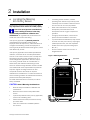
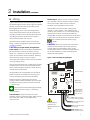
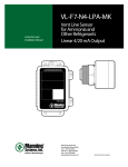
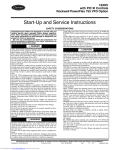
Ammonia-specific Electrochemical Gas Sensor/Transmitter
Manning EC-F9-NH3
Instruction and Installation Manual
04/13
Certified for electrical shock and electrical fire hazard only.
La certification couvre uniquement les risques de chocs électriques et d’incendies d’origine électrique.
Release F
Honeywell Confidential and Proprietary
This work contains valuable, confidential, and proprietary information. Disclosure, use
or reproduction outside of Honeywell Inc. is prohibited except as authorized in writing.
This unpublished work is protected by the laws of the United States and other countries.
Notices and Trademarks
Copyright 2013 by Honeywell International Inc.
Release F April 2013
While this information is presented in good faith and believed to be accurate, Honeywell disclaims the implied
warranties of merchantability and fitness for a particular purpose and makes no express warranties except as may
be stated in its written agreement with and for its customers.
In no event is Honeywell liable to anyone for any indirect, special, or consequential damages. The information and
specifications in this document are subject to change without notice.
Manning is a registered trademark of Honeywell International Inc.
Other brand or product names are trademarks of their respective owners.
Honeywell Analytics
23500 W. 105th St. MD 400
Olathe, KS 66061
847 955 8200
800 538 0363
[email protected]
www.honeywell.com
Manning EC-F9-NH3 Sensor 19186 ECF9NH3 10/2006 REVE Copyright © 2006 Honeywell Analytics. All Rights Reserved.
2
About This Document
World Wide Web
The following Honeywell web sites may be of interest to Industry Solution customers.
Honeywell Organization
WWW Address (URL)
Corporate
www.honeywell.com
Honeywell Analytics
www.honeywellanalytics.com
Manning Gas Detection
www.manningsystems.com
Telephone
Contact us by telephone at the numbers listed below.
O r g a n iz a tio n
United States / Canada
Service
Asia Pacific
P h o n e N u m be r
Honeywell Analytics Inc.
Lincolnshire, IL
1-800-538-0363
Honeywell Asia Pacific Inc.
H ong K ong
(852) 23 31 9133
1-800-321-6320
Europe
Honeywell PACE
Brussels, Belgium
{32-2} 728-2711
Latin America
Honeywell International Inc.
Lincolnshire, IL
1-847-955-8200
Sales Information
Contact us at [email protected]
Manning EC-F9-NH3 Sensor 19186 ECF9NH3
3
Symbol Definitions
The following table lists those symbols used in this document to denote certain conditions.
Symbol
Definition
ATTENTION: Identifies information that requires special consideration.
TIP: Identifies advise or hints for the user, often in terms of performing a task.
REFERENCE-EXTERNAL: Identifies an additional source of information outside of
this bookset.
REFERENCE-INTERNAL: Identifies an additional source of information within this
bookset.
CAUTION
indicates a situation which, if not avoided, may result in equipment or work (data) on
the system being damaged or lost, or may result in the inability to properly operate the
process.
CAUTION: Indicates a potentially hazardous situation which, if not avoided, may result
in minor or moderate injury. It may also be used to alert against unsafe practices.
CAUTION symbol on the equipment refers the user to the product manual for
additional information. The symbol appears next to required information in the manual.
Manning EC-F9-NH3 Sensor 19186 ECF9NH3
4
Contents
Serial number:
Section
Title
1
System Description
6
Specifications
6
2
3
Installation
7
A Locating the Manning EC-F9-NH3 Sensor
7
B Wiring
9
Operation
11
A Start-up Procedures
11
B Pushbutton Operation and LED Indicators
11
LED Blink Sequence
11
LED Sequence Indicator and Operation Summary
SensorCheckTM
13
14
4/20 mA Loop Check
14
Simple Zero Test
15
Span Calibration Mode
15
Modbus Address Change
17
C Troubleshooting
18
D Maintenance
19
EC Cell Replacement Procedure
4
Page
19
E Replacement Parts
19
Limited Warranty
20
Introduction
This manual has been prepared to help in the use and installation of the Manning EC-F9-NH3 (ElectrochemicalAmmonia) Sensor. This manual will convey the operating principles of the sensor, ensure proper installation, and
demonstrate start-up and routine maintenance procedures for the sensor.
ATTENTION: This manual must be carefully followed by all individuals who have or will have the
responsibility for using or servicing the sensor. Warranties made by Honeywell Analytics with respect
to this equipment will be voided if the equipment is not used and serviced in accordance with the instructions in this
manual. If in doubt about a procedure, please contact Honeywell Analytics before proceeding.
Manning EC-F9-NH3 Sensor 19186 ECF9NH3
5
1
System Description
The Manning EC-F9-NH3 Sensor is a three-wire,
4/20 mA sensor, with optional RS-485 Modbus RTU
communication, designed for low-level ammonia
detection available in ranges of 0—100 ppm,
0—250 ppm, 0—500 ppm, and 0—1,000 ppm.
The unit exhibits excellent accuracy and precision,
with negligible response to common interference
gases and dramatic changes in relative humidity.
Reliable trip levels as low as 25 ppm can be
expected with the 0—100 ppm sensor. The unit
exhibits extremely high reliability with no moving
parts.
Monitoring equipment must be configured to indicate
a fault if the signal is less than 1.5 mA. All signals
over 20 mA must be considered a high gas
concentration.
Specifications
Method: Electrochemical (diffusion)
Ranges: 0—100 ppm (standard)
0—250 ppm
0—500 ppm
0—1,000 ppm (requires High-Range cell)
Output: Isolated 4/20 mA, 700 ohms max at 24
VDC. Signal output reduces to 0.5 mA to indicate a
fault condition.
RS-485 Protocol: MODBUS RTU
Accuracy: ± 5% generally, but limited by available
calibration gas accuracy
Repeatability: ± 2% full scale
Response Time: T50 = 10 seconds,
T100 = 1 second for concentrations >1% NH3
Sensor Viability Test: An internal microprocessor
determines the sensor’s electrical viability every 24
hours (SensorCheckTM). Should the electrical viability
test fail, a 0.5 mA signal will indicate a fault.
A red LED on the circuit board will indicate if a
sensor is degraded electrically, dried up or
disconnected.
Manning EC-F9-NH3 Sensor 19186 ECF9NH3
4/20 mA Loop Viability Test: Internal monitoring of
4/20 mA output impedance
Operating Humidity: 5—100% RH (condensing).
ATMOS equipped® enviro-adaptive technology
option required for condensing conditions or
refrigerated areas, and all outdoor applications.
Operating Temperatures: —50o F to +120o F.
ATMOS equipped® enviro-adaptive technology
option required for refrigerated areas or outdoors.
Sensor Pressure Limits: 0—10 PSIG
Power Source: 24 VDC (recommended), 0.5 amp
max. 14—26 VDC acceptable. NOTE: If sensor is
ATMOS equipped®, contact Honeywell Analytics if
supply voltage is less the 16 VDC.
Cable Recommendations:
4/20 output: #18/3 shielded cable (Belden #8770 or
equal), cable runs <1,500 feet.
Modbus RTU (RS-485): For communication cable,
use 24 AWG twisted pair, shielded (Belden #9841 or
equal), cable runs up to 2,000 feet. For power cable,
use 14 AWG (Belden #5100UE or equal), cable runs
up to 1,000 feet, for each power supply. Larger power
cable and/or additional power supplies may be
required for longer cable runs and/or increased
number of sensors. Due to variables such as sensor
current draw, line loss, and cable size, contact
Honeywell Analytics for help with power requirements.
Gas Sampling: Diffusion method is standard.
Enclosure: NEMA 1, gasketed, #16-gauge steel
(standard). Stainless steel or explosion-proof
designs, including modified enclosures for low
temperatures, ventilation ducts, etc., are available
(contact Honeywell Analytics).
NOTE: The standard EC is for use in nonclassified areas only.
Weight: 3 lbs.
Dimensions: 6" high x 4" wide x 3.5" deep
6
2
A
Installation
Locating the Manning
EC-F9-NH3 Sensor
Because each sensor is a point measurement, it is
very important that the sensor be located properly.
One of the most important considerations
when installing EC sensors is that they
must be easily accessible for calibration and
maintenance. As a general rule, locate sensors no
closer than one foot from the ceiling.
If the primary application is personal protection
(representative concentration reading that an
employee would be exposed to), mount the sensor at
a height in the breathing zone of the employees. It
would typically be about five feet off the ground, which
also allows easy access.
If the primary application is the fastest possible leak
detection, mount the sensor near the potential leak
sources. In the case of ammonia, this is usually near
the ceiling as ammonia vapor is lighter than air. In
certain refrigeration applications, ammonia vapors
from an NH3 leak will remain at a low elevation. In
these cases, leak detection will take longer if the
sensor is mounted at high elevation and the indicated
concentration will not be representative of personnel
exposure. Higher mounting locations can also
complicate access to the sensor for required
calibration and maintenance. For more information on
sensor mounting locations for different leak scenarios,
please contact Honeywell Analytics.
No matter where the sensor is mounted, it must be
easily accessible.
•
If mounting sensor outdoors, consider
prevailing wind direction and proximity to the
most likely source of leaks. Protect the sensor
from sun and rain as much as possible.
•
Never mount the sensor in CA (controlled
atmosphere) rooms because normal
atmospheric level of oxygen is required for
operation.
•
For highly critical locations, more than one
sensor should be installed in each room.
•
To prevent electrical interference, keep sensor
and wire runs away from mercury vapor lights,
variable speed drives, and radio repeaters.
•
Protect sensor from physical damage (fork
lifts, etc.).
•
Do not mount the sensor over a door in a
refrigerated area.
Figure 1. Mounting Dimensions
2"
5/16" diameter
MOUNT ENCLOSURE THIS END UP
DO NOT BLOCK PERFORATED VENT HOLES.
Manning Gas Sensor
6 3/4"
CAUTION General Mounting Considerations:
•
Must be easily accessible for calibration and
maintenance.
•
Mount the sensor close to the potential leak
source.
•
If personnel protection is the primary application,
mount in the “breathing zone”.
•
Protect sensor from water, excessive humidity,
and wash-down.
•
Take air movement and ventilation patterns
into account.
Manning EC-F9-NH3 Sensor 19186 ECF9NH3
7
2
Installation continued
CAUTION
•
Sensor must be mounted vertically.
•
Never mount flat on a ceiling.
•
Enter enclosure only through existing hole in
bottom.
•
Always make a drip loop in the conduit (see
Figure 1).
Blast Freezers: Never mount sensor above the coil.
The ideal location, when possible, is below the
bottom of the coil. Try to put in return air and protect
the unit from being damaged by product loading and
unloading. Keep it away from warm, moist air during
defrost. Usually four or five feet off the ground is the
best location.
Ceiling-Hung Evaporators: When mounting
Manninh EC sensors near evaporators, mount the
sensor no higher than two feet below the top of the
evaporator coil. DO NOT mount in high air flow
(1,200 feet/ minute maximum). NEVER mount the
sensor on evaporators as vibration can damage the
sensor.
Other Locations: When mounting Manning EC
sensors in locations such as roof top air units, ductwork, attic spaces, makeup air intakes, etc., contact
Honeywell Analytics for application assistance
and recommendations.
Penthouses:
Multi-Coil (defrost one coil at a time): In this case the
best location is usually in the center of the penthouse
four or five feet above the grate.
Single Coil (or when all coils defrost at the same time):
In this case high moisture conditions can occur and
the sensor should be mounted one foot above the
grate.
Engine Rooms: The Manning EC sensor should be
mounted in a cool part of the room, if possible. Keep
the sensor away from hot air exhausting from electric
motors or other machinery. Usually the best location
is four or five feet above the floor in a location where
the room exhaust fan will move air across the sensor
from the potential leak source.
Manning EC-F9-NH3 Sensor 19186 ECF9NH3
8
2
B
Installation continued
Wiring
Figure 2 presents 4/20 mA output wiring information
for the Manning EC-F9-NH3 sensor. Figure 3 presents
RS-485 communication wiring information for the
Manning EC-F9-NH3 sensor.
Electrical wiring must comply with all applicable
codes. Plant equipment that may be involved and
operating conditions should be discussed with local
operating personnel to determine if any special
needs should be taken into account.
Almost all start-up problems are due to improper
wiring or monitor configuration. Please follow these
guidelines carefully.
CAUTION Do not pull sensor wiring with AC
power cables. This will cause electrical interference.
Be sure there are no breaks or splices in sensor
wiring runs. If cable runs cannot be made without a
splice, all connections must be soldered. Soldering
should be done using a rosin flux to tie the
connecting ends of sensor wires to ensure a positive
and long-lasting contact.
Ground the shield at the main control panel. Connect
the shield wire in the sensor terminal block labeled
SHLD. Tape all exposed shield wire at the sensor to
insulate it from the enclosure.
RS-485 output: Always use two conductor twisted
pair, insulated, stranded, shielded copper cable for
the communication cable. Use two conductor,
insulated, stranded cable for sensor power.
With RS-485, the communication cabling of the
network is “daisy chained”, with multiple devices
(sensors, relay modules, etc.) communicating along
the same pair of wires. If used with the Manning
AirAlertTM96d controller, up to 32 devices can be wired
in series per channel (up to three channels). Refer to
the controller manual for specific wiring
details.
CAUTION When many sensors are connected to
one set of power cables, total current draw may
exceed cable recommendations and/or cause
considerable line-loss. Contact Honeywell Analytics
for recommendations on power cable sizing and
additional power supplies.
Figure 2. 4/20 mA Output Wiring Diagram
NH3
SENSOR
PPM
SW1
All penetrations into a refrigerated room should be
sealed to prevent condensate from forming in the
conduit and dripping into the sensor enclosure.
Note 1: Pushbutton
LED
G
R
Y
TEST(+)
Make drip loops for cables going into sensor
housings. When heated enclosures are used, follow
the special mounting instructions on the enclosure
(…This End Up).
40 to
200 MVDC
Mount sensor enclosures through the flange
holes as shown in Figure 1, and always
mount vertically.
Note 2: Mode
Indicator LEDs
TEST(-)
JP1
JP3
A
EC-F9
B
E.O.L.
4/20 mA output: Always use three conductor,
insulated, stranded, shielded copper cable. Use only
three conductor cable, not two cables of two
conductor wire.
SHLD
GND
+24
SIG
Fake-out resistor
Remove factoryinstalled 100 ohm,
fake-out resistor
White—Connects to signal
input of monitoring equipment
Always respect
minimum volt
agerequirements at
device.
Red—From +24 VDC terminal
of power supply
Black—From Ground terminal
of power supply
Outside bare wrap—From
“SHLD” terminal of controller
Manning EC-F9-NH3 Sensor 19186 ECF9NH3
9
2
Installation continued
Electrical Power: 24 VDC regulated, 30 mA. With
an ATMOS equipped® enclosure the current draw is
400 mA max.
Respect minimum voltage requirements.
Outputs:
ATTENTION: The Manning EC-F9 sensor is
shipped with a 100 ohm, 1/4 watt resistor in
the green, four position terminal block, across the
Signal and Ground terminals (see Figure 3). This
resistor is needed to “fake out” the 4/20 mA loop if
using the Modbus RTU output. Only remove this
resistor if using the 4/20 mA output.
NOTE for PLC applications: The signal
output load can range from 0 to 700 ohms,
where the maximum load resistor at a 24 VDC supply
is 700 ohms and the maximum load resistor at a 10
VDC supply is 267 ohms. Any load outside these
values will indicate a fast flash on the red LED while
in operation or this test mode during normal
operation. The error LED will blink fast at any time if
the signal output cannot source the necessary
current.
Figure 3. RS-485 Communication and
Power Wiring Diagram
4/20 mA: Circuit board mounted sensor provides a
linear 4/20 mA output. Monitoring equipment may
have a maximum input impedance of 700 ohms.
EC-F9-NH3
SN:
SPAN
RS-485: MODBUS RTU communication protocol.
Cable Recommendation:
NH3
4/20 mA output: Use #18/3 shielded cable (Belden
#8770 or equivalent). Length of cable to sensor
should be no greater than 1,500 feet. Use only the
existing punched holes for connections to the
sensor.
PPM
SENSOR
SW1
LED
RS-485: For communication cable, use 24 AWG
twisted pair, shielded (Belden #9841 or equal), cable
runs up to 2,000 feet. Avoid “T-taps” if possible. Do
not exceed 65 feet per T-tap. Do not exceed 130 feet
total of all T-taps (per channel). For power cable, use
14 AWG (Belden #5100UE or equal), cable runs up
to 1,000 feet, for each power supply. Larger power
cable and/or additional power supplies may be
required for longer cable runs and/or increased
number of sensors. Due to variables such as sensor
current draw, line loss, and cable size, contact
Honeywell Analytics for help with power cable
requirements.
CAUTION Follow cable recommendations.
Monitoring: The Manning EC-F9-NH3 Ammonia
Sensor may be monitored by the Manning GM-10,
GM-4, GM-1, GM-JR, AirAlertTM96d, or other
appropriately configured system. For 4/20 output,
monitoring equipment must be configured to indicate
a fault if the signal is below 1.5 mA. All signals over
20 mA must be considered a high gas concentration,
not a fault condition.
Manning EC-F9-NH3 Sensor 19186 ECF9NH3
G
R
Y
TEST(+)
40 to
200 MVDC
TEST(-)
JP1
JP3
A
EC-F9
B
SHLD
GND
+24
SIG
E.O.L.
End of line resistor
On the last sensor of the
communication network, a
jumper must be installed
Fake-out resistor
If 4/20 mA output is not used,
a 100 Ohm, 1/4 Watt resistor
must be installed as shown
White—From “A”
terminal of controller to
“A” terminal of next device
Red—From +24 VDC terminal of
power supply
Black—From “B”
terminal of controller to
“B” terminal of next device
Black—From Ground terminal of
power supply
Outside bare wrap—From “SHLD”
terminal of controller
10
3
A
Operation
Start-Up Procedures
Before applying power, make a final check of all
wiring for continuity, shorts, grounds, etc. It is usually
best to disconnect external alarms and other
equipment from the sensor until the initial start-up
procedures are completed. SensorCheckTM is initiated
each time the unit is powered up.
After power-up, allow 24 hours for the system to
stabilize before testing the sensors. Because sensors
are normally located at a distance from the main unit,
the test time required and accuracy of the response
checks will be improved if two people perform the
start-up procedures and use radio contact.
Simple Start-Up Test:
•
One person exposes each sensor to a small
amount of the gas that is being monitored.
•
The second person stays at the control unit to
determine that each sensor, when exposed to
the gas fumes, is connected to the proper input
and responds, causing appropriate alarm
functions.
•
For press and hold activations, one’s finger
must always be applying a down pressure
without disruption for the specified time in order
to activate the desired mode.
•
See complete details of each
operation in other parts of the manual.
The Manning EC-F9-NH3 has been designed with
three distinct test mode procedures that are
triggered by the appropriate push button action.
These test modes include Manual SensorCheckTM,
Simple Zero Test, and 4/20 mA Loop Check.
The fourth operation puts the unit into Calibration
Mode to allow for testing with a certified calibration
gas standard and to provide information for
appropriate span adjustments, if required.
Figure 4. LED Blink Sequence
SLOW BLINK
MEDIUM BLINK
FAST BLINK
B
Pushbutton Operation and
LED Indicators
CONTINUOUS ON
The Manning EC-F9-NH3 has an internal pushbutton
that is utilized for navigation of test functions and
operating modes (see Figure 5, Note 5). It also has a
group of LEDs (green, red, yellow — see Figure 3)
that blink in specific sequences to indicate sensor
operation modes. A summary of sensor operation
modes and corresponding LED blink sequences is
shown in Figure 6. The pushbutton must be pressed
the correct number of times and at the correct rate.
•
When a multi-press sequence must be
performed, the button must be pressed rapidly
and evenly, lifting one’s finger completely from
the actuator for each consecutive press.
Manning EC-F9-NH3 Sensor 19186 ECF9NH3
11
3
Operation continued
Green LED
•
Solid ON — all modes except Cal. and 4/20 mA
calibration.
•
Slow Blink — Calibration mode.
Red LED
•
•
•
•
Solid ON — Possible catastrophic failure on the
circuit board. The 4/20 mA signal will vary
depending on the exact failure. In the event of
corrupted data, calibration values and Modbus
ID may be lost but the gas sensor and 4/20 mA
output circuit would still be operational. In the
event of a CPU failure, a 0.5 mA fault signal is
output from the sensor. All other functions and
devices would be inoperable (optional LCD,
network, pushbuttons, etc.). Contact Honeywell
Analytics for technical support.
Slow Blink — Near death, possible dried up or
disconnected Cell. A 0.5 mA fault signal is
output from the sensor during this error event.
A replacement cell should be ordered at this
time.
Medium Double Blink — Possible weak cell.
Cell is nearing the end of its useful life.
Although the sensor may pass the span
calibration or detect the presence of ammonia,
frequent attention and increased calibration
checks are strongly recommended until the cell
is replaced.
Green — ON, Red — Fast Blink, Yellow — Fast Blink
•
4/20 mA loop test failed the 22 mA high
extremity. Check output impedance and ensure
it is between 10Ω and 700Ω referenced to
ground. In addition, ensure power supply
voltage is within specified operating range.
Figure 5. Manning EC-F9-NH3 Sensor Components
Note 5: Pushbutton
Note 1: Span adjustment
Note 4: Sensor cable plugs
in here. Verify that sensor
is plugged in properly and
cable is secured.
EC-F9-NH3
SN:
SPAN
NH3
SENSOR
PPM
SW1
LED
G
R
TEST(+)
Fast Blink — Possible 4/20 mA loop failure or
load resistance too high. Check output
impedance and ensure it is between 10Ω and
700Ω referenced to ground. In addition, ensure
power supply voltage is within specified
operating range.
Solid ON — During Sensor CheckTM.
•
Medium Double Blink — During 4/20 mA (0.5
mA low) test.
•
Fast Blink — During 4/20 mA (22 mA high) test
and during failed (22 mA high) test.
Note 2: LEDs
40 to
200 MVDC
TEST(-)
JP1
JP3
Yellow LED
•
Y
A
EC-F9
B
SHLD
GND
+24
SIG
E.O.L.
LCD module connector
40-200 mV
mVDC
Risk of electrical shock.
Black
-
Red
+
Note 3: Sensor output
Manning EC-F9-NH3 Sensor 19186 ECF9NH3
12
3
Operation continued
Figure 6. LED Sequence Indicator and Operation Summary
MODE
G
GREEN LED (left)
R
RED LED (center)
Y
YELLOW LED (right)
NOTE
Normal
Run Mode
During Span
Calibration Mode
3
During Simple
Zero Test
Manual
SensorCheck™
1
Weak Cell
Failed or
Disconnected Cell
2
Hardware failure
2
During 4/20 mA
Loop Test
(22 mA high)
Failed Loop Test
(22 mA high)
During 4/20 mA
Loop Test
(.5 mA low)
Failed Signal
Output
4
NOTE 1: SensorCheck™ automatically every 24 hours. Manual test can be initiated.
NOTE 2: Unit will output 0.5 mA.
NOTE 3: Exits mode after 10 minutes or if pushbutton is pressed for one second.
NOTE 4: Occurs due to wiring problem or incorrect load value.
= Initiated by button press
Manning EC-F9-NH3 Sensor 19186 ECF9NH3
13
3
Operation continued
TM
SensorCheck
4/20 mA Loop Test
SensorCheckTM is a microprocessor-based technology
that monitors and predicts the electrical viability of its
electrochemical and infrared ammonia sensors by
testing every 24 hours. If the sensor dries up or is
disconnected, SensorCheckTM sends an indication that
can be detected by a Manning Gas Monitor or PLC.
NOTE: This test is recommended especially for PLC
operations (non-Manning readout/alarm unit).
The red LED will indicate if a sensor starts to degrade
electrically causing marginal operation requiring
frequent attention and increased calibration checks.
Should the electrical viability test fail, the unit outputs
a 0.5 mA signal to indicate this fault condition.
The SensorCheckTM electrical viability test is
not, however, meant to replace adherence to
the factory-recommended calibration schedule.
SensorCheckTM is an internal electrical test that is not
capable of verifying physical aspects such as
blockage of the sensor membrane by dirt, flour,
grease, water, paint, etc.
Physical blockage is rare, but does occasionally
happen, especially in many harsh processing
environments.
NOTE: SensorCheckTM is not intended to measure or
indicate the chemical viability of a sensor operating
in high or continuous concentration of NH3.
Although SensorCheckTM is performed automatically
every 24 hours, at any time a manual sensor check
can be performed.
To perform a manual SensorCheckTM, follow the
procedure below:
Start: Press button (see Figure 4, Note 5) three
times within two second time limit (test takes about
15 seconds). During test, green and yellow LED’s are
both continuous ON.
G
Continuous ON
Y
Continuous ON
Exit: Unit resumes normal mode automatically after
about 20 seconds. Green LED remains continuous
ON and yellow LED is unlit.
G
Continuous ON
Y
LED is OFF
Manning EC-F9-NH3 Sensor 19186 ECF9NH3
NOTE: This test will not automatically time out. You
must force the unit into normal operation.
Full Scale Test: This test will verify that the full-scale
output of the sensor is also achieved at the PLC.
Start: Place meter leads on Test (+) and Test (—).
Press button five times within a two- or three-second
period of time. The voltmeter should read
approximately 220 mV (equal to 22.0 mA output).
Verify full-scale signal at PLC. NOTE: some PLCs
limit input to 20 mA. Blink sequence will be:
G
Continuous ON
Y
Fast blink
Signal Fault Test: This test will simulate one of many
sensor fault conditions in which the transmitter will
send 0.5 mA to the control panel. To check for
downscale fault verification, press button for one
second (voltmeter should read approximately 5 mV
(equal to 0.5 mA output). Verify downscale fault
indication at PLC. Blink sequence will be:
G
Continuous ON
Y
Medium blink
PLC and monitoring equipment should indicate
Fault at this extremely low signal output, (i.e.,
Honeywell Analytics recommends fault indication on
any signal below 1.5 mA.)
Exit: Press and hold button for one second. Sensor
will exit test and return to normal operation.
G
Continuous ON
NOTE: This test will not automatically time out. You
must force the unit into normal operation.
14
3
Operation continued
Simple Zero Test
Span Calibration Mode
Start: With meter set to mVDC, place leads on
Test (+) and Test (—) (see Figure 4, Note 3). Press
and hold button for one second to enter the
Calibration Mode.
NOTE: If using the Modbus RTU output with
the Manning AirAlertTM96d controller, while in
calibration mode, alarms A, B, and C will not be
activated during calibration of the sensor.
Slow blink
G
•
Unplug the cell from the pre-amp.
•
Observe the 4/20 mA signal which should be
approximately 4.0 mA (40 mV on meter). Range
should be 39.4 to 40.6 mV. If sensor output is
not in this range, contact Honeywell Analytics.
•
Plug cell back into pre-amp. Wait for cell to
stabilize at approximately 4.0 mA.
Exit: Press and hold button for one second (places
unit in Normal Operation Mode).
G
Continuous ON
PLC and monitoring equipment should indicate Fault
at this extremely low signal output, (i.e., Honeywell
Analytics recommends fault indication on any signal
below 1.5 mA.)
Exit: Press and hold button for one second. Sensor
will exit test and return to normal operation. Blink
sequence will be:
G
Manning EC-F9-NH3 Sensor 19186 ECF9NH3
Continuous ON
NOTE: When replacing an aged or nonresponsive cell, the new cell may cause an
erratic or jumpy signal, sometimes causing false
alarms. This is usually caused by excessive gain
leftover from adjusting the span pot (increasing the
sensitivity) for the old cell. Once the span calibration
is performed on the new cell, the gain will be
decreased to match the sensitivity of the new cell,
reducing the jumpiness of the new cell.
NOTE: It is not recommended that any span
gas with a concentration lower than 1/2 of
the full-scale range is used for span calibration. For
example, for a 0/500 ppm ranged sensor, do not use
span gas lower than 250 ppm.
The Manning EC-F9-NH3 comes factory calibrated
and should require minimal adjustments after
installation. There is one pot on the preamp that is
used for Span calibration (see Figure 4,
Note 1). There is no zero pot as the pre-amp
is factory zeroed and should not require any further
adjustment.
Calibration Kits are available from Honeywell
Analytics. Each calibration kit contains certified
calibration gas and complete detailed instructions for
calibration of all Manning sensors.
15
3
Operation continued
Span Calibration
Span Signal Formula
The unit is factory calibrated and normally does not
need to be spanned upon initial installation. Do not
adjust the span pot without certified calibration gas!
Normal span gas is full scale. In case it is not full
scale, use the following formula:
If span calibration is required, follow the procedure
below:
Signal (mA) =
x 16 + 4
Where:
Start:
•
ASGC
SFSV
With meter set to mVDC, place leads on Test
(+) and Test (—).
•
Make sure signal is resting at 4.0 mA. If sensor
is not outputting 4.0 mA, see Troubleshooting
on Page 18.
•
Press and hold button for 1—2 seconds. Green
LED shows slow blink during test procedure.
G
ASGC = Available Span Gas Concentration
SFSV = Sensor Full Scale Concentration Value
Example: If 100 ppm ASGC gas is used to calibrate
a 250 ppm SFSV sensor, the signal would be as
follows:
Signal =
100 ppm
250 ppm
x 16 + 4 = 10.4 mA
Slow blink
10.4 mA = 104 mV from TEST (—) to TEST (+)
•
Apply span gas at 0.8 L/min (span gas must be
in air, not nitrogen or other carrier).
•
After span gas has been on sensor for a
maximum of two minutes or achieving peak
level, adjust the span pot until the correct
output is achieved (see Figure 4, Note 1).
•
If full scale calibration gas is used, output
should be 200 mV. If required, use “Span”
potentiometer to adjust output to 200 mV (20
mA). If “mid-range” cal gas is being used, refer
to the formula in the following section.
If the correct output cannot be achieved, a
replacement cell is required.
Exit: Press and hold button for one or two seconds.
Green LED (left) on continuous (normal operation).
G
Continuous ON
NOTE: The Span Calibration Mode will automatically
time out after 10 minutes.
Manning EC-F9-NH3 Sensor 19186 ECF9NH3
16
3
Operation continued
MODBUS Address Change
11
NOTE: To view or change the Modbus
TM
address, the Manning CalPro LCD Module
is required. Contact Honeywell Analytics to obtain the
module.
12
NOTE: No two devices on the network can
have the same address. Each device needs to
have a unique address.
Each device requires an address to communicate
with the controller on the network. The Modbus
address normally comes factory programmed and
does not require to be programmed at startup. If it is
determined that the Modbus address needs to be
Using the LCD module to view or change the
Modbus address: The LCD module has two pushbuttons; Accept and Scroll, which will be utilized for
this procedure (see Figure 7).
13
If the Modbus address is not correct, using the
Accept and Scroll buttons, change the Modbus
address the correct value.
You will then be prompted to save the changes.
Press Accept to save, and Scroll to abort. You
will then be returned to the MAIN MENU.
Use scroll button to navigate through the main
menu. To exit the menu, scroll until the LCD
displays Quit? and press the Accept button. This
will return you to normal operating mode. The
LCD module can be unplugged at this time.
NOTE: After 5 minutes of inactivity, the LCD returns to
normal (idle) operating display.
Figure 7. CalProTM LCD Module
EC-F9-NH3
SN:
NOTE: To display the Modbus address, press the
Scroll button anytime during normal operating mode.
1
2
3
4
5
6
7
8
9
10
Plug in the LCD module to the LCD port on the
PCB (see Figure 7).
This module will power-up immediately and will
display the normal (idle) operating display.
Press the Accept button.
You will then be prompted for a password. The
password is MA.
Use the Scroll button to change the first letter to
M. Then press the Accept button.
You will then be prompted to change the
second letter. If it is already set to A, press the
Accept button.
If the correct password is entered, you will be
sent to the MAIN MENU.
In the MAIN MENU, scroll until the ModbsID?
screen is displayed.
Press Accept to enter Modbus Address Change
menu. The current programmed Modbus
address will be displayed (if not programmed
at the factory, the default address is 001).
If the Modbus address is correct, keep pressing
the Accept button until you are prompted to
accept the current Modbus address. You will
then be returned to the MAIN MENU.
SPAN
NH3
SENSOR
PPM
SW1
LCD Module
Plug
LED
G
R
Y
TEST(+)
40 to
200 MVDC
TEST(-)
ECF9 NH3
JP3
0 PPM
JP1
A
EC-F9
Accept
B
SHLD
GND
+24
SIG
E.O.L.
Scroll
Risk of electrical
shock.
Manning EC-F9-NH3 Sensor 19186 ECF9NH3
17
3
C
Operation continued
Troubleshooting
Figure 8. Troubleshooting
Note 5: Pushbutton
Risk of electrical shock.
The LEDs will give visual indication of several sensor
and transmitter conditions.
Note 1: Span adjustment
If the sensor output is 0 mA: First, verify +24 VDC
at the sensor terminal block (see Figure 8, Note 2).
Second, check voltage between Test (—) and Test (+)
(see Figure 8, Note 3). Voltage should be in the
range of 40 mV to 200 mV corresponding to an
actual current flow of 4 mA to 20 mA. If this voltage is
0 mV, the signal has no path to ground. Check
monitoring equipment connections and configuration.
Note 4: Sensor cable plugs
in here. Verify that sensor
is plugged in properly and
cable is secured.
EC-F9-NH3
SN:
SPAN
NH3
SENSOR
If the sensor output is 0.5 mA: Indicates a fault
condition has occurred.
•
•
Most common — failed or disconnected sensor
Hardware failure (pre-amp)
PPM
SW1
If the sensor output is erratic: Make sure that the
unit is in clean, ammonia-free air.
The unit has been factory zeroed and spanned. If the
zero has become unstable, and there are no interference gases, the most likely problem is a faulty or
aged cell, or a new cell with high gain left over from a
previous cell that was adjusted for aging. If span
calibration has not been performed with the new cell,
turn span pot down (see Figure 7, Note 1), or counterclockwise, 15 full turns. This will decrease the
sensitivity and reduce the “jumpiness” of the new cell.
Calibration is definitely required after this adjustment.
Electrical Interference: This sensor has been
designed to be highly resistant to EMI/RFI using multiple
stages of filtering and protection. However, in extreme
environments, some noise pickup can occur directly
through the sensor. Ensure that the bare shield wire of
the instrument cable is connected to the terminal block
marked SHLD at the sensor (not touching the metal
enclosure) and properly grounded at the readout unit.
Interference Gases: The Manning EC-F9-NH3 is
designed to be quite specific to ammonia. However,
some other gases can affect the reading. Phosphene,
methyl mercaptan, and hydrogen can give a slight
upscale indication. Bromine, ozone, fluorine, chlorine,
and nitrogen dioxide can give a slight down-scale
indication. Contact Honeywell Analytics if any of these
gases are present in your application.
Manning EC-F9-NH3 Sensor 19186 ECF9NH3
LED
G
R
Y
TEST(+)
40 to
200 MVDC
TEST(-)
JP1
JP3
A
EC-F9
B
SHLD
GND
+24
SIG
E.O.L.
20-24 V
40-200 mV
VDC
mVDC
Black
-
Red
+
Note 2: Power supply voltage
Black
-
Red
+
Note 3: Sensor output
18
3
D
Operation continued
Maintenance
For proper operation it is essential that the test and
calibration schedule be followed. Honeywell
Analytics recommends the following maintenance
schedule:
•
Calibration should be performed with certified
calibration gas every six months or after major
exposure to a leak. Calibration kits are
available from Honeywell Analytics.
•
Response test once between calibrations, i.e.
at three month intervals. Expose sensor to
ammonia/water solution to verify proper sensor
response and alarm functions. Test more
frequently in highly critical applications. The
response test is not required if multiple electrochemical sensors are installed in the same
room.
When the cell becomes depleted, a replacement cell
can be obtained from Honeywell Analytics. Simply
unplug the ribbon cable from the pins labeled
Sensor, pull the old cell from the spring clip, discard
the old cell and replace it with a new one.
The sensor should be checked according to the
following procedure after a five-minute warm-up
period.
EC Cell Replacement Procedure
•
Remove the old EC cell.
•
Plug in new EC cell, making sure connector
pins are positioned correctly. Be sure
ribbon cable is snug under plastic clip
(see Figure 8, Note 4).
•
Allow cell to stabilize for five minutes.
•
Perform manual SensorCheckTM using the
procedure in the SensorCheckTM section.
All tests and calibrations must be logged.
Sensor Life: These electrochemical cells are
extremely reliable, but several things can cause the
cell chemicals to become depleted including:
•
a period of time,
•
exposure to high temperatures,
•
exposure to varying concentrations of the
target gas,
•
exposure to high moisture for extended periods
without proper sensor enclosure.
Manning Systems’ recommendation is to check
calibration of all new cells with certified calibration
gas. Follow procedure in Calibration section of this
manual.
E
Replacement Parts
For replacement parts, contact Honeywell Analytics.
Be sure to give serial number of unit and model
number.
CAUTION Although SensorCheck tests the
TM
sensor’s electrical viability every 24 hours, it is
absolutely essential that these units be exercised
with a gas sample on a regular and timely basis.
Typical sensor life in a refrigerated area will be three
to four years. Typical life in a non-refrigerated area
will be one and a half to two years. Exposure to high
levels of ammonia will shorten these times. In
addition to timely response checks, a preventative
maintenance program of periodic cell replacement
should be implemented.
Manning EC-F9-NH3 Sensor 19186 ECF9NH3
19
4
1.
2.
Limited Warranty
Limited Warranty
Honeywell Analytics, Inc. warrants to the
original purchaser and/or ultimate customer
(“Purchaser”) of Manning products (“Product”)
that if any part thereof proves to be defective in
material or workmanship within eighteen (18)
months of the date of shipment by Honeywell
Analytics or twelve (12) months from the date of
first use by the purchaser, whichever comes
first, such defective part will be repaired or
replaced, free of charge, at Honeywell Analytics’
discretion if shipped prepaid to Honeywell
Analytics at 405 Barclay Blvd., Lincolnshire, IL
60069, in a package equal to or in the original
container. The Product will be returned freight
prepaid and repaired or replaced if it is
determined by Honeywell Analytics that the
part failed due to defective materials or
workmanship. The repair or replacement of any
such defective part shall be Honeywell
Analytics’ sole and exclusive responsibility and
liability under this limited warranty.
Exclusions
A. If gas sensors are part of the Product, the
gas sensor is covered by a twelve (12)
month limited warranty of the manufacturer.
B. If gas sensors are covered by this limited
warranty, the gas sensor is subject to
inspection by Honeywell Analytics for
extended exposure to excessive gas concentrations if a claim by the Purchaser is
made under this limited warranty. Should
such inspection indicate that the gas sensor
has been expended rather than failed
prematurely, this limited warranty shall not
apply to the Product.
C. This limited warranty does not cover consumable items, such as batteries, or items
subject to wear or periodic replacement,
including lamps, fuses, valves, vanes, sensor
elements, cartridges, or filter elements.
Manning EC-F9-NH3 Sensor 19186 ECF9NH3
3.
Warranty Limitation and Exclusion
Honeywell Analytics will have no further obligation
under this limited warranty. All warranty obligations
of Honeywell Analytics are extinguishable if the
Product has been subject to abuse, misuse,
negligence, or accident or if the Purchaser fails to
perform any of the duties set forth in this limited
warranty or if the Product has not been operated in
accordance with instructions, or if the Product
serial number has been removed or altered.
4.
Disclaimer of Unstated Warranties
THE WARRANTY PRINTED ABOVE IS THE ONLY
WARRANTY APPLICABLE TO THIS PURCHASE.
ALL OTHER WARRANTIES, EXPRESS OR IMPLIED,
INCLUDING, BUT NOT LIMITED TO, THE IMPLIED
WARRANTIES OF MERCHANTABILITY OR
FITNESS FOR A PARTICULAR PURPOSE ARE
HEREBY DISCLAIMED.
5.
Limitation of Liability
IT IS UNDERSTOOD AND AGREED THAT
HONEYWELL ANALYTIC’S LIABILITY, WHETHER
IN CONTRACT, IN TORT, UNDER ANY
WARRANTY, IN NEGLIGENCE OR OTHERWISE
SHALL NOT EXCEED THE AMOUNT OF THE
PURCHASE PRICE PAID BY THE PURCHASER
FOR THE PRODUCT AND UNDER NO
CIRCUMSTANCES SHALL HONEYWELL
ANALYTICS BE LIABLE FOR SPECIAL, INDIRECT,
OR CONSEQUENTIAL DAMAGES. THE PRICE
STATED FOR THE PRODUCT IS A CONSIDERATION LIMITING HONEYWELL ANALYTICS’
LIABILITY. NO ACTION, REGARDLESS OF FORM,
ARISING OUT OF THE TRANSACTIONS UNDER
THIS WARRANTY MAY BE BROUGHT BY THE
PURCHASER MORE THAN ONE YEAR AFTER
THE CAUSE OF ACTIONS HAS OCCURRED.
20