1
13. ERROR CODES
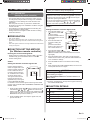
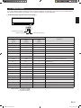
If you use a wireless remote controller, the lamp on the photo detector unit will output error codes by way of blinking patterns.
See the lamp blinking patterns in the table. An error display is displayed only during operation.
[ Troubleshooting with the indoor unit display ]
OPERATION lamp (green)
TIMER lamp (orange)
ECONOMY lamp (green)
Error display
OPERATION
lamp
(green)
TIMER
lamp
(orange)
ECONOMY
lamp
(green)
● (1)
● (1)
◊
Serial communication error
● (3)
● (2)
◊
Indoor unit PCB model information error
● (3)
● (5)
◊
Manual auto switch error
● (4)
● (1)
◊
Room temp. sensor error
● (4)
● (2)
◊
Indoor unit Heat Ex. Middle temp.sensor error
● (5)
● (1)
◊
Indoor unit fan motor error
● (5)
● (15)
◊
Indoor unit error
● (6)
● (2)
◊
Outdoor unit main PCB model
information error or communication error
● (6)
● (3)
◊
Inverter error
● (6)
● (4)
◊
Active filter error, PFC circuit error
● (6)
● (5)
◊
Trip terminal L error
● (6)
● (10)
◊
Display PCB microcomputers communication error
● (7)
● (1)
◊
Discharge temp. sensor error
● (7)
● (3)
◊
Outdoor unit Heat Ex. liquid temp. sensor error
● (7)
● (4)
◊
Outdoor temp. sensor error
● (8)
● (4)
◊
Current sensor error
● (9)
● (4)
◊
Trip detection
● (9)
● (5)
◊
Compressor rotor position detection error
● (9)
● (7)
◊
Outdoor unit fan motor error
● (9)
● (9)
◊
4-way valve error
● (10)
● (1)
◊
Discharge temp. error
Description
Display mode ● : 0.5s ON / 0.5s OFF
◊ : 0.1s ON / 0.1s OFF
( ) : Number of flashing
En-15
9332622027_IM.indb 15
2012-9-29 8:36:58