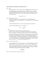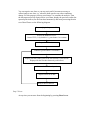
1
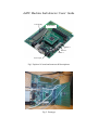
dsPIC Machine fault detector: Users’ Guide
LCD display
Reset Button
Button 3
Button 2
Button 1
Power input
Fig.1 Explorer 16 board and some useful descriptions.
Fig. 2. Prototype
Operation steps of the harmonic based fault detector:
Step 1. Start
Referring to figures 1 and 2, when you press the Reset button or turn the system
on by plugging in the power input (the power is supplied by a power adapter
Microchip Technology, SN 20182, input 100-240 V AC and output is 9 V DC,
700 mA), the LCD will display the copy right information and then displays the
following message:
Num of FCC (1-4):
Step 2. Input number of FCC’s
Here the user is asked to enter the number of FCC’s (Fault Characteristic
Coefficients) (Note: in the C programs, FCC is represented by FCF) that are going
to be analysed.
As the default number of FCC’s is one, to pass this step just press button 1.
The LCD will then display (FCC1 = the first FCC):
FCC1
00.000
U
Note:
o To adjust the FCC button you need to use buttons 2 and 3.
o Button 3 relocates the U sign to the location of the digit that can be changed.
o Button 2 changes the value of the digit that is above the U sign. Each time this
button is pressed the digit increases by one and when it passes 9 it will return to 0.
o For example, if the desired FCC1 is 05.230, we can shift U (by pressing the 3rd
button once) to the 2nd digit (from left) and press the 2nd button five times (to get
“5”), then shift the U to the 3rd digit (from left), then press the 2nd button twice (to
get “2”), then shift the U to the 4th digit (from left) and then press the 2nd button
three times (to get “3”). Now the LCD will display 05.230.
Step 3. Acquire and analyze data
After inputting the FCC1 value, press button 1 to collect data (though you could
run the system for any time duration, only 1 sec of data will be collected) and
analyse the incoming vibration data. From this point on, the user is not asked to
enter any parameters. The processor will continue using the already entered FCC.
The following is displayed when the analysis is finished.
Continue?
Step 4. Collect and analyze new data (if necessary)
You can acquire new data, or you may wait until it becomes necessary to
collect/analyze new data, e.g., when the shaft speed or any other conditions
change. For this purpose you may press button 1 to continue the analysis. Then
the microprocessor will acquire a new set of data; display the previous results (the
spectral peak indices (for the first three harmonics)) and starts processing the new
set of data. Please see the following diagram:
Reset or plug in the power cable
Ask for the number of FCCs:
“Num of FCC (1-4) (default is 1), press button 1 to continue
Input the FCC1 value
Continue? (press button 1 to continue)
Display previous results (if this is the first iteration 3 zeros will be
displayed for the first three harmonic peak indices)
Estimate shaft rotational speed
Acquire a new set of data
Analyse the new data set
Step 5. Reset
At any time you can start from the beginning by pressing Reset button.