1
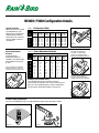
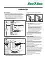
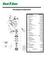
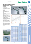
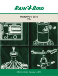
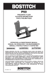
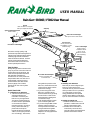
USER MANUAL
Rain Gun® SR3003 / F3002 User Manual
Nozzle
Refer to Table 2 to integrate
with spoon adjustment bracket
Arm Stop
Spoon Adjustment Bracket
Refer to table 2
Rear Arm Counterweight
Pulls spoon into the water stream
Pressure Port
Check pressure here
at installation or when
troubleshooting
Front Arm Counterweight
Rain Guns are high quality, high
performance sprinklers designed for a
variety of uses and applications where
relatively high flows and extended
radius of throw are desired. For best
results, please read the following
instructions before construction to
ensure optimal performance.
Rear Counterweight
Used in sloping
installations where
riser is not set
vertical to horizon
(sold separately)
Start Up Note
Always verify pressure. Pressure at the
pump or point of connection does not
equal pressure at the sprinkler. The
most common problem associated
with sprinkler installations is
insufficient or too much pressure at
the sprinkler head. Your Rain Gun is
equipped with a pressure port to
accommodate a 1/4" NPT thread
pressure gauge, also included,
specifically for this critical system
pre-check.
Quick Start Guide
1. Configuring Your Rain Gun
a. A set of 6 nozzles and a spoon
adjustment bracket are
included to customize your
Rain Gun to your application.
The spoon bracket allows you
to set the rotation speed based
on the nozzle size and the
pressure at the gun. To ensure
a fast, problem free start up,
please refer to the spoon
bracket adjustment guide (Ref.
Table 2) to configure your Rain
Gun accordingly. The nozzles,
NPT or BSP Thread Adapter
Used to mount Rain Gun
to threaded riser
along with the pressure at the
Rain Gun, dictate flow rate and
radius of throw and should be
selected accordingly.
b. If you are using a part circle
Rain Gun, manually set the
desired rotation arc by pushing
the two friction collars to the
desired position (See Figure 3
of Installation Tips).
c. Flush pipeline delivery system
prior to installing Rain Gun.
d. If you are using the BSP or NPT
adapter, make sure that it is
securely bolted to the Rain Gun
using the 6 bolts and gasket
supplied. Make sure that the
adapter is securely tightened to
the 2" riser.
2. Installing Your Rain Gun
Now that you have configured your
Rain Gun, make sure that it is
mounted securely. If there is wobble
while your Rain Gun is in operation,
it is a signal that you are losing
energy needed to ensure optimal
rotation speed. Refer to Installation
Tips for more information if needed.
3. Starting Your Rain Gun
a. Make sure that the Rain Gun is
pointed in a safe direction and all
people in the area are ready.
b. Activate valve if automatic. If
controlled by a manual valve,
open valve slowly until the desired
pressure and flow are reached.
SR3003 / F3002 Configuration Details
Nozzle Selection
Select one of the six nozzles
provided based on your
performance requirements,
available water pressure
(at the Rain Gun), and flow
capacity. Refer to Table 1
and Figure 1.
Spoon Adjustment
Bracket
Install the Spoon
Adjustment Bracket, if
needed, in accordance with
Table 2. Refer to Figures A,
B, and C.
Figure A: Bracket not installed
Provides maximum drive and
rotation speed at low pressures.
Table 1 – Performance
Data
NOZZLE SIZE
(.55")
PSI @
Nozzle
40
50
60
70
80
90
100
14 mm
(ft.)
(gpm)
Rad.
103
109
115
121
128
134
140
Flow
55
61
66
72
77
82
88
(.63")
16 mm
(.71")
18 mm
(ft.)
(gpm)
(ft.)
Rad.
105
111
120
126
128
135
141
Flow
72
79
86
93
99
106
113
Rad.
113
124
133
140
146
151
154
Table 2 – Spoon
(gpm)
Flow
92
101
110
118
127
136
144
(.79")
(.87")
20 mm
(ft.)
(gpm)
Rad.
131
137
141
146
153
159
164
Flow
114
124
136
147
157
168
178
(.94")
22 mm
(ft.)
(gpm)
Rad.
126
136
140
149
161
168
176
Flow
134
148
162
175
188
201
214
24 mm
(ft.)
(gpm)
Rad.
126
137
142
151
166
175
184
Flow
162
177
193
209
224
240
255
Adjustment Bracket
NOZZLE SIZE
(.55")
(.63")
(.71")
(.79")
(.87")
(.94")
14 mm
16 mm
18 mm
20 mm
22 mm
24 mm
40
A
A
A
A/B
A/B
A/B
45
A
A/B
A/B
A/B
A/B
A/B
50
A/B
B
B
B
B
B
60
A/B
B
B
B
B
B
65
B
B
B
B
B/C
B/C
75
B
B
B
B/C
B/C
B/C
80
B
B
B/C
C
C
C
90
B
B
B/C
C
C
C
95
B
B/C
B/C
C
C
C
100
B
B/C
B/C
C
C
C
PRESSURE
PSI
Example (see shaded area):
You have 60 PSI and a 14 mm nozzle; the chart
recommends configuration A or B. This means that your
Rain Gun® will operate properly in either configuration,
but the rotation speed will be faster in A than in B.
Rotation Angle Adjustment
For part circle (SR3003) model only, adjust desired rotation angle manually as shown.
Rotation Angle
Figure 2
Figure 3
Figure 1
Figure B: Plus position (+)
Provides an intermediate
position to regulate rotation
speed at intermediate pressures.
Figure C: Minus position (–)
Provides greatest slowing of
rotation speed at high pressures.
Installation Tips
Riser Installation
a. To ensure proper operation and performance for the life of
your Rain Gun, the riser must be stable and solidly installed to
resist vibration. An unsupported riser is insufficient for proper
operation. Additionally, a PVC riser will not support the
reaction load of a Rain Gun. Some options that may be used
are: (Note: confirm friction loss and flow in your application)
• Option 1: Galvanized riser strapped to a 6" x 6" pressure
treated wood post (See Figure 4).
Figure 4
Max. of 72” height is
recomended. Post should be
continuous to base of Rain Gun.
Use hi-torque
stainless steel bands
Keep riser vertical
Min. of 36” depth
is recommended.
Compact dirt
around post.
2" Elbow swing
assembly
Lateral
Provide drain valve
as necessary
Use pressure
treated wood
Figure 5
2” Galv.sch. 40
Using thread adapter
Figure 6
Using bolt flange
Figure 7
c. Inclined operation:
• The preferred installation on an inclined plane
is on a vertical riser regardless of angle of
incline.
• If the riser must be set at an angle, use the rear
counterweight (part number L00270) for
proper rotation of your Rain Gun. The weight is
designed to help the Rain Gun rotate up hill.
• If you are using a portable gun stand, please
consult the manufacturer to be sure it is
designed to support inclined terrain.
d. For more help with your installation, please call
your Rain Bird Dealer or District Manager. The
toll free Rain Bird number is listed on the back
page of this guide.
Traveler Installation
• Option 2: Galvanized riser set in a pillar of concrete
(See Figure 5).
12” to bolt
flange
b. Install Rain Gun to riser as shown in Figure 6
or 7.
10”
12”
a. Make sure that the pressure at the gun is over
45 psi. Most users underestimate the pressure loss
in the pipe, which is very high. Adjust your spoon
bracket in relation to the nozzle size and the
pressure at the gun.
b. On sloped terrain, weight compensation may be
required for proper rotation. For such conditions,
a rear counterweight is available (Part number
L00270, sold separately).
c. As an alternative to using a counterweight, some
travelers can be vertically adjusted.
Center Pivot Installation
Dimensions of concrete
required will vary depending on riser height, soil
bearing capacity, and
Rain Gun flowrate.
Example shown is for
compact clay soil with
18 mm nozzle and
maximum pressure 80 psi.
2" Elbow swing assembly
Lateral
Provide drain valve
as necessary
• Option 3: A portable gun stand designed to support a Rain
Gun. (Contact your dealer for a recommended supplier.)
a. For proper operation, make sure that the pressure
at the gun is over 45psi. Many users underestimate
the pressure loss in the pivot, which is very high,
especially at the end-gun location. Adjust your
spoon bracket in relation to the nozzle size and
the pressure at the gun (Refer to spoon bracket
adjustment guide, Table 2).
b. Make sure that the pivot end-gun mounting
position is stable.
Parts Diagram and Description
Ref.
1
2
3
4
5
6
7
8
9
10
11
12
13
14
15
16
17
18
19
20
21
22
23
24
25
26
27
28
29
35
36
37
38
Part Description
Arm Shaft Assembly
Arm Assembly/Counterweight
Spoon Assembly
Spacer
Snap Ring
Pivot Cap Assembly
Pivot Assembly
Arm Spring
Spring Spacer
Arm Locknut
Arm Washer
Counterweight Kit
Elbow/Range Tube Assembly
O-Ring
Brake Assembly
Bearing Assembly
Friction Collar (2 Required)
Snap Ring
Ball Bearing
Lock Nut
O-Ring
Bearing Sleeve
Trip Lever Assembly
Trip Link Bushing
Elbow Shaft Washer (3 Required)
Cotter Pin (3 Required)
Trip Rod
Nozzle Retainer
GNS-3003T Nozzle Set
Spring, Red (8 Required)
Pressure Port Plug (1/4")
Spoon Bracket
Dry Pressure Gauge (not shown)
Accessories
30 2" Female BSP Adapter
31 2" Female NPT Adapter
32 Bearing Wrench
33 Riser Installation Kit
34 Rear Counterweight
Part Numbers
Included in Kit B
71-P50472
71-P50824
71-P50420
71-P00358
71-P50825
71-P50826
71-P50812
71-P50706
Included in Kit B
Included in Kit B
71-P50827
71-P50471
71-P50155
71-P51176
71-P50976
71-P50116
71-P50463
71-P50544
71-P50793
71-P50121
71-P50794
71-P50538
71-P50539
Included in Kit A
Included in Kit A
71-P50478
71-105943
L003003
71-P51165
71-P20006
71-P51099
DV160
71-P50545
71-P50596
71-P50697
71-P50368
L00270
Spare Parts Kit
A
B
Misc. Kit
Arm Shaft Kit
71-P50590
71-P50591
Troubleshooting Tips
Should you experience operating
difficulties, here are some tips that
may apply to your application. For
further assistance, please record the
date code, the serial number on the
elbow, and the pressure at the gun,
and call your Rain Bird Dealer or the
toll free Rain Bird number listed at the
back of this guide.
Rotation speed too fast
Rain Gun does not rotate
or rotation speed is too slow
Rotation speed varies from
one direction to another
• Install a 1/4" pressure gauge into
the Rain Gun pressure port and
verify adequate operating pressure.
Refer to Spoon Bracket Adjustment
guide (table 2) for proper
configuration of spoon bracket
based on nozzle size. Also check
the spoon and the arm for damage.
• Check that the spoon is properly
installed on the arm.
• Check that the arm is not bent.
• Check that the nozzle is properly
installed in the nozzle housing.
It should be seated squarely.
• Check the condition of the spoon.
If broken, it will need to be
replaced.
• Make sure that the trip stops are
not loose by pushing against them
with your finger. (See Figure 3)
• Turn your gun manually to the trip
stops. They should hold when the
trip lever pushes against them.
• If your Rain Gun has recently been
re-assembled, make sure that the
trip lever was not reinstalled in
between the trip stops. This will
open the trip mechanism and not
stop the Rain Gun.
Gun does not reverse
Arm does not move
• Install a pressure gauge at the Rain
Gun pressure port and refer to
Spoon Bracket Adjustment guide
(Table 2) for proper configuration
of spoon bracket to nozzle size.
Pressure at gun should not exceed
100 psi.
• Check trip mechanism by manually
operating it. Operation should be
free and smooth.
• Check trip mechanism spring. It
must have tension and be properly
installed.
• Check bushings at the trip
mechanism. They must be clean
and not damaged.
• Check the pressure at the gun
• Check that the nozzle is properly
installed on the nozzle housing
• Make sure that the nozzle retainer
is tightened
• Check that the spoon is not broken
• Check that the mechanical stop
(arm stop) on the arm is not
damaged
• Check that the arm is not bent
• If pressure is below specification
and the Rain Gun is properly
configured, decrease the nozzle
size to increase pressure at the gun.
• If pressure is lower than it was at
installation, check for obstructions
in the water line. You may be able
to flush obstructions from the
sprinkler and water line by
removing the nozzle and turning
on the water.
• If pressure is still low after
removing obstructions, and your
Rain Gun still does not rotate, you
may need to add a booster pump or
increase pressure in another way.
Install a pressure gauge at the Rain
Gun pressure port and refer to Spoon
Bracket Adjustment guide (table 2) for
proper configuration of spoon bracket
to nozzle size. Also check the spoon
for damage. For proper operation, the
operating pressure at the gun should
not exceed 100 psi.
Arm stroke frequency is
too high
• Make sure pressure is not above
100 psi.
• Make sure the front arm
counterweight is installed
(below spoon).
• Make sure the rear arm
counterweight is installed.
Gun rotation slows down
over time
• Refer to first troubleshooting tip
above for non-rotating or slow
rotation.
Trip stop mechanism is not
holding the gun at the
desired arc
Rain Gun® Warranty
Agricultural Applications
Non-agricultural Applications
Our latest generation of Rain Guns is built on a legacy of
knowledge, trust, and feedback from end users like you.
Our warranty is simple and in line with Rain Bird’s reputation
as the most reliable agricultural sprinkler in the world.
To back up our claim, we offer the best warranty in the
agriculture industry. For all agricultural applications, we
offer a three year, no questions asked warranty including
free service or parts replacement.
We understand that Rain Guns are often utilized in
applications that may be more demanding than general
agricultural applications. In these circumstances, Rain Bird
offers an eighteen month warranty including free service or
parts replacement, but excludes coverage in the following
general applications or environments:
• Electrolytic conditions, such as high salt environments
or salt water spray applications
• Applications where environmental conditions are not
compatible with the materials used in Rain Guns
• Caustic or corrosive chemical conditions or spray
applications
• Abrasive fluid spray applications
Rain Bird International, Inc.
145 N. Grand Ave.
Glendora, CA 91741-2469
Phone: (626) 963-9311
Fax: (626) 963-4287
Rain Bird Agri-Products Co.
633 W. Foothill Blvd.
Glendora, CA 91741-2469
Phone: (800) 435-5624
Fax: (626) 852-7310
www.rainbird.com
® Registered trademark of Rain Bird Sprinkler Mfg. Corp.
© 2002 Rain Bird Sprinkler Mfg. Corp. 7/02
PN L357