1
ForeRunner ® HE
ATM Adapters for IRIX
Systems
User’s Manual
MANU0404-01
Revision A
05-13-1999
Software Version 5.1
FORE Systems, Inc.
1000 FORE Drive
Warrendale, PA 15086-7502
Phone: 724-742-4444
FAX: 724-742-7742
http://www.fore.com
fs
Notices
St. Peter's Basilica image courtesy of ENEL SpA and InfoByte SpA. Disk Thrower image courtesy of Xavier Berenguer, Animatica.
Copyright © 1998 Silicon Graphics, Inc. All Rights Reserved. This document or parts thereof may not be reproduced in any
form unless permitted by contract or by written permission of Silicon Graphics, Inc.
LIMITED AND RESTRICTED RIGHTS LEGEND
Use, duplication, or disclosure by the Government is subject to restrictions as set forth in the Rights in Data clause at FAR
52.227-14 and/or in similar or successor clauses in the FAR, or in the DOD, DOE or NASA FAR Supplements. Unpublished
rihts reserved under the Copyright Laws of the United Stated. Contractor/manufacturer is Silicon Graphics, Inc., 2011 N.
Shoreline Blvd., Mountain View, CA 94043-1389.
Autotasking, CF77, CRAY, Cray Ada, CraySoft, CRAY Y-MP, CRAY-1, CRInform, CRI/TurboKiva, HSX, LibSci, MPP
Apprentice, SSD, SUPERCLUSTER, UNICOS, X-MP EA, and UNICOS/mk are federally registered trademarks and
Because no workstation is an island, CCI, CCMT, CF90, CFT, CFT2, CFT77, ConCurrent Maintenance Tools, COS, Cray Animation Theater, CRAY APP, CRAY C90, CRAY C90D, Cray C++ Compiling System, CrayDoc, CRAY EL, CRAY J90, CRAY
J90se, CrayLink, Cray NQS, Cray/REELlibrarian, CRAY S-MP, CRAY SSD-T90, CRAY SV1, CRAY T90, CRAY T3D, CRAY
T3E, CrayTutor, CRAY X-MP, CRAY XMS, CRAY-2, CSIM, CVT, Delivering the power . . ., DGauss, Docview, EMDS, GigaRing, HEXAR, IOS, ND Series Network Disk Array, Network Queuing Environment, Network Queuing Tools, OLNET, RQS,
SEGLDR, SMARTE, SUPERLINK, System Maintenance and Remote Testing Environment, Trusted UNICOS, and UNICOS
MAX are trademarks of Cray Research, Inc., a wholly owned subsidiary of Silicon Graphics, Inc.
DynaText and DynaWeb are registered trademarks of Inso Corporation. Silicon Graphics and the Silicon Graphics logo are
registered trademarks of Silicon Graphics, Inc. UNIX is a registered trademark in the United States and other countries,
licensed exclusively through X/Open Company Limited. X/Open is a trademark of X/Open Company Ltd. The X device
is a trademark of the Open Group.
The UNICOS operating system is derived from UNIX . System V. The UNICOS operating system is also based in part on
the Fourth Berkeley Software Distribution (BSD) under license from The Regents of the University of California.
FCC CLASS A NOTICE
WARNING: Changes or modifications to this unit not expressly approved by the party responsible for compliance could
void this user’s authority to operate this equipment.
NOTE: The devices referenced in this manual have been tested and found to comply with the limits for a Class A digital
device, pursuant to Part 15 of the FCC Rules. These limits are designed to provide reasonable protection against harmful
interference when the equipment is operated in a commercial environment. This equipment generates, uses, and can radiate radio frequency energy and, if not installed and used in accordance with the instruction manual, may cause harmful
interference to radio communications. Operation of the equipment in a residential area is likely to cause harmful interference in which case the user is required to correct the interference at his own expense.
DOC CLASS A NOTICE
This digital apparatus does not exceed Class A limits for radio noise emission for a digital device as set out in the Radio
Interference Regulations of the Canadian Department of Communications.
Le present appareil numerique n’emet pas de bruits radioelectriques depassant les limites applicables aux appareils numeriques de la class A prescrites dans le reglement sur le brouillage radioelectrique edicte par le ministere des Communications du Canada.
VCCI CLASS 1 NOTICE
This is a Class A product based on the standard of the Voluntary Control Council for Interference by Information
Technology Equipment (VCCI). If this equipment is used in a domestic environment, radio disturbance may arise. When
such trouble occurs, the user may be required to take corrective actions.
CE NOTICE
Marking by the symbol CE indicates compliance of this system to the EMC (Electromagnetic Compatibility) directive of the
European Community and compliance to the Low Voltage (Safety) Directive. Such marking is indicative that this system
meets or exceeds the following technical standards:
• EN 55022 - “Limits and Methods of Measurement of Radio Interference Characteristics of Information Technology Equipment.”
• EN 50082-1 - “Electromagnetic compatibility - Generic immunity standard Part 1: Residential, commercial,
and light industry.”
• IEC 1000-4-2 - “Electromagnetic compatibility for industrial-process measurement and control equipment
Part 2: Electrostatic discharge requirements.”
• IEC 1000-4-3 - “Electromagnetic compatibility for industrial-process measurement and control equipment
Part 3: Radiate electromagnetic field requirements.”
• IEC 1000-4-4 - “Electromagnetic compatibility for industrial-process measurement and control equipment
Part 4: Electrical fast transient/burst requirements.”
SAFETY CERTIFICATIONS
ETL certified to meet Information Technology Equipment safety standards UL 1950, CSA 22.2 No. 950, and EN 60950.
TRADEMARKS
FORE Systems, ForeRunner, ForeView, ForeThought, ForeRunnerLE, PowerHub and AVA are registered trademarks of FORE Systems, Inc. Cellpath, EdgeRunner, Zero Hop Routing, MSC, TNX, VoicePlus, StreamRunner, Universal Port, ASN, CellStarter,
Intelligent Infrastructure, I2, NetPro, FramePlus, ForeRunnerHE, ASX, Network of Steel, and Networks of Steel are trademarks
of FORE Systems, Inc. All other brands or product names are trademarks of their respective holders.
Table of Contents
List of Figures
List of Tables
Preface
Chapter Summaries. . . . . . . . . . . . . . . . . . . . . . . . . . . . . . . . . . . . . . . . . . . . . . . . . . . . . . . . . . i
Silicon Graphics Product Support . . . . . . . . . . . . . . . . . . . . . . . . . . . . . . . . . . . . . . . . . . . . . . iii
Typographical Styles . . . . . . . . . . . . . . . . . . . . . . . . . . . . . . . . . . . . . . . . . . . . . . . . . . . . . . . . iv
Important Information Indicators . . . . . . . . . . . . . . . . . . . . . . . . . . . . . . . . . . . . . . . . . . . . . . . .v
Safety Agency Compliance . . . . . . . . . . . . . . . . . . . . . . . . . . . . . . . . . . . . . . . . . . . . . . . . . . . vi
Safety Precautions . . . . . . . . . . . . . . . . . . . . . . . . . . . . . . . . . . . . . . . . . . . . . . . . . . . vi
Symbols . . . . . . . . . . . . . . . . . . . . . . . . . . . . . . . . . . . . . . . . . . . . . . . . . . . . . . . . . . . vi
Modifications to Equipment . . . . . . . . . . . . . . . . . . . . . . . . . . . . . . . . . . . . . . . . . . . . vi
CHAPTER 1
1.1
1.2
1.3
1.4
Introduction
Overview of the ATM Standard . . . . . . . . . . . . . . . . . . . . . . . . . . . . . . . . . . . . . . . . . . . . 1 - 1
Overview of LANE/MPOA . . . . . . . . . . . . . . . . . . . . . . . . . . . . . . . . . . . . . . . . . . . . . . . . 1 - 1
LANE Primer . . . . . . . . . . . . . . . . . . . . . . . . . . . . . . . . . . . . . . . . . . . . . . . . . . . . . . . . . . 1 - 2
1.3.1 LANE Components . . . . . . . . . . . . . . . . . . . . . . . . . . . . . . . . . . . . . . . . . . . . . 1 - 2
1.3.2 Example LANE Configuration . . . . . . . . . . . . . . . . . . . . . . . . . . . . . . . . . . . . . 1 - 3
1.3.2.1 Initialization Process . . . . . . . . . . . . . . . . . . . . . . . . . . . . . . . . . . . . . . . 1 - 4
1.3.2.2 Connection Process. . . . . . . . . . . . . . . . . . . . . . . . . . . . . . . . . . . . . . . . 1 - 5
1.3.2.3 Multicast and Broadcast Packets . . . . . . . . . . . . . . . . . . . . . . . . . . . . . . 1 - 5
1.3.2.4 Accessing Fast Ethernet and FDDI Networks . . . . . . . . . . . . . . . . . . . . 1 - 5
1.3.2.5 Multiple ELANs . . . . . . . . . . . . . . . . . . . . . . . . . . . . . . . . . . . . . . . . . . . 1 - 6
1.3.2.6 Distributed LAN Emulation. . . . . . . . . . . . . . . . . . . . . . . . . . . . . . . . . . . 1 - 6
1.3.2.7 Automatic ELAN Selection . . . . . . . . . . . . . . . . . . . . . . . . . . . . . . . . . . . 1 - 6
1.3.2.8 Intelligent BUS . . . . . . . . . . . . . . . . . . . . . . . . . . . . . . . . . . . . . . . . . . . . 1 - 6
Introduction to Multi-Protocol Over ATM (MPOA) . . . . . . . . . . . . . . . . . . . . . . . . . . . . . . 1 - 7
1.4.1 LANE Without MPOA. . . . . . . . . . . . . . . . . . . . . . . . . . . . . . . . . . . . . . . . . . . . 1 - 7
1.4.2 Why MPOA? . . . . . . . . . . . . . . . . . . . . . . . . . . . . . . . . . . . . . . . . . . . . . . . . . . 1 - 8
1.4.3 MPOA Components. . . . . . . . . . . . . . . . . . . . . . . . . . . . . . . . . . . . . . . . . . . . . 1 - 9
1.4.4 MPOA Example . . . . . . . . . . . . . . . . . . . . . . . . . . . . . . . . . . . . . . . . . . . . . . . 1 - 10
1.4.4.1 MPS Configuration. . . . . . . . . . . . . . . . . . . . . . . . . . . . . . . . . . . . . . . . 1 - 11
1.4.4.2 Initialization . . . . . . . . . . . . . . . . . . . . . . . . . . . . . . . . . . . . . . . . . . . . . 1 - 12
1.4.4.3 Flow Analysis . . . . . . . . . . . . . . . . . . . . . . . . . . . . . . . . . . . . . . . . . . . . 1 - 12
1.4.4.4 Making a Shortcut . . . . . . . . . . . . . . . . . . . . . . . . . . . . . . . . . . . . . . . . 1 - 13
ForeRunner® HE ATM Adapters for IRIX® Systems User’s Manual
TOC - 1
Table of Contents
1.4.4.5 Shortcut Teardown . . . . . . . . . . . . . . . . . . . . . . . . . . . . . . . . . . . . . . . .1 - 14
1.5 ForeRunner Adapter Overview . . . . . . . . . . . . . . . . . . . . . . . . . . . . . . . . . . . . . . . . . . . .1 - 14
1.5.1 Hardware Overview . . . . . . . . . . . . . . . . . . . . . . . . . . . . . . . . . . . . . . . . . . . .1 - 14
1.6 Software Overview . . . . . . . . . . . . . . . . . . . . . . . . . . . . . . . . . . . . . . . . . . . . . . . . . . . . .1 - 15
1.6.1 Advanced Cell Processor Architecture . . . . . . . . . . . . . . . . . . . . . . . . . . . . . .1 - 16
1.6.2 Software Features. . . . . . . . . . . . . . . . . . . . . . . . . . . . . . . . . . . . . . . . . . . . . .1 - 17
1.7 Supported Platforms . . . . . . . . . . . . . . . . . . . . . . . . . . . . . . . . . . . . . . . . . . . . . . . . . . . .1 - 18
1.8 Unpacking Information . . . . . . . . . . . . . . . . . . . . . . . . . . . . . . . . . . . . . . . . . . . . . . . . . .1 - 18
1.9 HE155 Adapter Specifications . . . . . . . . . . . . . . . . . . . . . . . . . . . . . . . . . . . . . . . . . . . .1 - 20
1.10 HE622 Adapter Specifications . . . . . . . . . . . . . . . . . . . . . . . . . . . . . . . . . . . . . . . . . . . .1 - 21
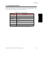
1.11 Cable Specifications . . . . . . . . . . . . . . . . . . . . . . . . . . . . . . . . . . . . . . . . . . . . . . . . . . . .1 - 23
CHAPTER 2
2.1
2.2
CHAPTER 3
3.1
3.2
Hardware Installation
General Installation Procedures . . . . . . . . . . . . . . . . . . . . . . . . . . . . . . . . . . . . . . . . . . . .2 - 1
Halting the System . . . . . . . . . . . . . . . . . . . . . . . . . . . . . . . . . . . . . . . . . . . . . . . . . . . . . .2 - 2
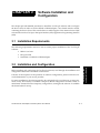
Software Installation and Configuration
Installation Requirements . . . . . . . . . . . . . . . . . . . . . . . . . . . . . . . . . . . . . . . . . . . . . . . . .3 - 1
Installation and Configuration . . . . . . . . . . . . . . . . . . . . . . . . . . . . . . . . . . . . . . . . . . . . . .3 - 1
3.2.1 Installation. . . . . . . . . . . . . . . . . . . . . . . . . . . . . . . . . . . . . . . . . . . . . . . . . . . . .3 - 2
3.2.1.1 Deviations . . . . . . . . . . . . . . . . . . . . . . . . . . . . . . . . . . . . . . . . . . . . . . . .3 - 7
3.2.1.2 Software Conflicts . . . . . . . . . . . . . . . . . . . . . . . . . . . . . . . . . . . . . . . . . .3 - 7
3.2.1.3 Hardware Conflicts . . . . . . . . . . . . . . . . . . . . . . . . . . . . . . . . . . . . . . . . .3 - 8
3.2.2 Installation Completion . . . . . . . . . . . . . . . . . . . . . . . . . . . . . . . . . . . . . . . . . . .3 - 8
3.2.3 Configuration . . . . . . . . . . . . . . . . . . . . . . . . . . . . . . . . . . . . . . . . . . . . . . . . . .3 - 9
3.2.3.1 Typical Configuration Session . . . . . . . . . . . . . . . . . . . . . . . . . . . . . . . .3 - 10
3.2.3.1.1
ATM Core Software. . . . . . . . . . . . . . . . . . . . . . . . . . . . . . . .3 - 10
3.2.3.1.1.1
Questions and Responses . . . . . . . . . . . . . . . . . .3 - 11
3.2.3.1.2
UNI Signalling Software . . . . . . . . . . . . . . . . . . . . . . . . . . . .3 - 12
3.2.3.1.2.1
Questions and Responses . . . . . . . . . . . . . . . . . .3 - 12
3.2.3.1.3
MPOA/LAN Emulation Software . . . . . . . . . . . . . . . . . . . . . .3 - 14
3.2.3.1.3.1
Questions and Responses . . . . . . . . . . . . . . . . . .3 - 16
3.2.3.1.4
Legacy Application QoS Software . . . . . . . . . . . . . . . . . . . .3 - 18
3.2.3.1.4.1
Questions and Responses . . . . . . . . . . . . . . . . . .3 - 18
3.2.3.1.5
Classical IP Software . . . . . . . . . . . . . . . . . . . . . . . . . . . . . .3 - 19
3.2.3.1.5.1
Questions and Responses . . . . . . . . . . . . . . . . . .3 - 19
3.2.3.1.6
SPANS Signalling Software . . . . . . . . . . . . . . . . . . . . . . . . .3 - 20
3.2.3.1.6.1
Questions and Responses . . . . . . . . . . . . . . . . . .3 - 21
3.2.3.1.7
FORE IP Software . . . . . . . . . . . . . . . . . . . . . . . . . . . . . . . .3 - 21
3.2.3.1.7.1
Questions and Responses . . . . . . . . . . . . . . . . . .3 - 22
TOC - 2
ForeRunner® HE ATM Adapters for IRIX® Systems User’s Manual
Table of Contents
3.2.3.2
3.2.4
CHAPTER 4
4.1
4.2
4.3
6.2
6.3
Network Interface Administration
Configuring FORE IP
Configuring an Outgoing FORE IP PVC . . . . . . . . . . . . . . . . . . . . . . . . . . . . . . . . . . . . .
5.1.1 Configuring an Incoming FORE IP PVC . . . . . . . . . . . . . . . . . . . . . . . . . . . . .
5.1.2 Verifying the FORE IP PVC Configuration. . . . . . . . . . . . . . . . . . . . . . . . . . . .
5.1.3 FORE IP Multicasting Support. . . . . . . . . . . . . . . . . . . . . . . . . . . . . . . . . . . . .
5.1.4 FORE IP Load Balancing and Automatic Failover . . . . . . . . . . . . . . . . . . . . . .
5.1.5 Settable Peak Cell Rate for FORE IP SVCs . . . . . . . . . . . . . . . . . . . . . . . . . .
5.1.6 IP MTU Size. . . . . . . . . . . . . . . . . . . . . . . . . . . . . . . . . . . . . . . . . . . . . . . . . . .
5.1.7 User Configurable FORE IP Network Interface Name. . . . . . . . . . . . . . . . . . .
CHAPTER 6
6.1
3 - 23
3 - 23
3 - 23
3 - 24
Network Interface Configuration . . . . . . . . . . . . . . . . . . . . . . . . . . . . . . . . . . . . . . . . . . . 4 - 1
4.1.1 Naming Conventions . . . . . . . . . . . . . . . . . . . . . . . . . . . . . . . . . . . . . . . . . . . . 4 - 1
4.1.2 Configuring the ForeRunner Adapter Network Interface . . . . . . . . . . . . . . . . . 4 - 2
4.1.3 Assigning IP Addresses During Reboots. . . . . . . . . . . . . . . . . . . . . . . . . . . . . 4 - 2
UNI Load Balancing and Failover . . . . . . . . . . . . . . . . . . . . . . . . . . . . . . . . . . . . . . . . . . 4 - 3
4.2.1 Configuring . . . . . . . . . . . . . . . . . . . . . . . . . . . . . . . . . . . . . . . . . . . . . . . . . . . 4 - 4
4.2.1.1 Command-Line Configuration . . . . . . . . . . . . . . . . . . . . . . . . . . . . . . . . 4 - 4
ForeRunner Adapter in an IP Network. . . . . . . . . . . . . . . . . . . . . . . . . . . . . . . . . . . . . . . 4 - 6
4.3.1 Multi-homing on ATM and Ethernet Networks . . . . . . . . . . . . . . . . . . . . . . . . . 4 - 7
4.3.2 Configuring a Workstation as ATM-Only . . . . . . . . . . . . . . . . . . . . . . . . . . . . . 4 - 8
4.3.3 Dynamic and Static IP Routing (ATM-Only Network). . . . . . . . . . . . . . . . . . . . 4 - 9
4.3.3.1 Dynamic Routing . . . . . . . . . . . . . . . . . . . . . . . . . . . . . . . . . . . . . . . . . . 4 - 9
4.3.3.2 Static Routing. . . . . . . . . . . . . . . . . . . . . . . . . . . . . . . . . . . . . . . . . . . . 4 - 10
CHAPTER 5
5.1
ATM Card Drivers. . . . . . . . . . . . . . . . . . . . . . . . . . . . . . . . . . . . . . . . .
3.2.3.2.1
HE Adapters . . . . . . . . . . . . . . . . . . . . . . . . . . . . . . . . . . . .
3.2.3.2.1.1
Questions and Responses . . . . . . . . . . . . . . . . .
Removal. . . . . . . . . . . . . . . . . . . . . . . . . . . . . . . . . . . . . . . . . . . . . . . . . . . . .
5-1
5-2
5-2
5-3
5-3
5-4
5-4
5-5
Configuring Classical IP
Introduction . . . . . . . . . . . . . . . . . . . . . . . . . . . . . . . . . . . . . . . . . . . . . . . . . . . . . . . . . . .
6.1.1 Logical IP Subnets. . . . . . . . . . . . . . . . . . . . . . . . . . . . . . . . . . . . . . . . . . . . . .
6.1.2 Classical IP Interfaces . . . . . . . . . . . . . . . . . . . . . . . . . . . . . . . . . . . . . . . . . . .
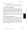
Address Registration and ILMI. . . . . . . . . . . . . . . . . . . . . . . . . . . . . . . . . . . . . . . . . . . . .
6.2.1 ATM Addresses . . . . . . . . . . . . . . . . . . . . . . . . . . . . . . . . . . . . . . . . . . . . . . . .
6.2.2 Operating with ILMI Support . . . . . . . . . . . . . . . . . . . . . . . . . . . . . . . . . . . . . .
6.2.3 Operating without ILMI Support. . . . . . . . . . . . . . . . . . . . . . . . . . . . . . . . . . . .
ARP and ARP Servers. . . . . . . . . . . . . . . . . . . . . . . . . . . . . . . . . . . . . . . . . . . . . . . . . . .
6.3.1 Theory . . . . . . . . . . . . . . . . . . . . . . . . . . . . . . . . . . . . . . . . . . . . . . . . . . . . . . .
6.3.2 Configuring a FORE Switch as an ARP Server. . . . . . . . . . . . . . . . . . . . . . . .
6.3.3 Classical IP Operation . . . . . . . . . . . . . . . . . . . . . . . . . . . . . . . . . . . . . . . . . . .
ForeRunner® HE ATM Adapters for IRIX® Systems User’s Manual
6-1
6-1
6-2
6-2
6-2
6-3
6-3
6-4
6-4
6-5
6-5
TOC - 3
Table of Contents
6.4
6.5
6.3.4 Operational Issues . . . . . . . . . . . . . . . . . . . . . . . . . . . . . . . . . . . . . . . . . . . . . .6 - 6
Classical IP PVCs . . . . . . . . . . . . . . . . . . . . . . . . . . . . . . . . . . . . . . . . . . . . . . . . . . . . . . .6 - 7
6.4.1 Theory and Configuration . . . . . . . . . . . . . . . . . . . . . . . . . . . . . . . . . . . . . . . . .6 - 7
6.4.2 Re-validation and Removal. . . . . . . . . . . . . . . . . . . . . . . . . . . . . . . . . . . . . . . .6 - 7
Configuring the Network . . . . . . . . . . . . . . . . . . . . . . . . . . . . . . . . . . . . . . . . . . . . . . . . . .6 - 9
6.5.1 Third-Party Switch with ILMI Support . . . . . . . . . . . . . . . . . . . . . . . . . . . . . . . .6 - 9
6.5.2 Third-Party Switch with RFC-1577 and No ILMI Support . . . . . . . . . . . . . . . .6 - 10
CHAPTER 7
7.1
7.2
7.3
7.4
7.5
Configuring an ELAN
Introduction . . . . . . . . . . . . . . . . . . . . . . . . . . . . . . . . . . . . . . . . . . . . . . . . . . . . . . . . . . . .7 - 1
Emulated LAN Components . . . . . . . . . . . . . . . . . . . . . . . . . . . . . . . . . . . . . . . . . . . . . . .7 - 1
7.2.1 LAN Emulation Client (LEC) . . . . . . . . . . . . . . . . . . . . . . . . . . . . . . . . . . . . . . .7 - 2
7.2.2 LAN Emulation Configuration Server (LECS) . . . . . . . . . . . . . . . . . . . . . . . . . .7 - 2
7.2.3 LAN Emulation Server (LES) . . . . . . . . . . . . . . . . . . . . . . . . . . . . . . . . . . . . . .7 - 3
7.2.4 Broadcast and Unknown Server (BUS) . . . . . . . . . . . . . . . . . . . . . . . . . . . . . .7 - 3
Emulated LAN Operation . . . . . . . . . . . . . . . . . . . . . . . . . . . . . . . . . . . . . . . . . . . . . . . . .7 - 4
7.3.1 Initialization . . . . . . . . . . . . . . . . . . . . . . . . . . . . . . . . . . . . . . . . . . . . . . . . . . . .7 - 5
7.3.2 Registration and Address Resolution . . . . . . . . . . . . . . . . . . . . . . . . . . . . . . . .7 - 6
7.3.3 Data Transfer . . . . . . . . . . . . . . . . . . . . . . . . . . . . . . . . . . . . . . . . . . . . . . . . . .7 - 7
Distributed LAN Emulation . . . . . . . . . . . . . . . . . . . . . . . . . . . . . . . . . . . . . . . . . . . . . . . .7 - 8
7.4.1 Single Server LANE Services Model . . . . . . . . . . . . . . . . . . . . . . . . . . . . . . . .7 - 8
7.4.1.1 Using a Single Server . . . . . . . . . . . . . . . . . . . . . . . . . . . . . . . . . . . . . . .7 - 8
7.4.1.2 Limitations of a Single Server . . . . . . . . . . . . . . . . . . . . . . . . . . . . . . . .7 - 10
7.4.2 Distributed LAN Emulation Model. . . . . . . . . . . . . . . . . . . . . . . . . . . . . . . . . .7 - 10
7.4.2.1 Using DLE. . . . . . . . . . . . . . . . . . . . . . . . . . . . . . . . . . . . . . . . . . . . . . .7 - 11
7.4.2.2 Advantages of DLE . . . . . . . . . . . . . . . . . . . . . . . . . . . . . . . . . . . . . . . .7 - 13
7.4.2.2.1
Load Sharing . . . . . . . . . . . . . . . . . . . . . . . . . . . . . . . . . . . .7 - 13
7.4.2.2.2
Improved Performance for Remote LECs . . . . . . . . . . . . . . .7 - 13
7.4.2.2.3
Fault Tolerance . . . . . . . . . . . . . . . . . . . . . . . . . . . . . . . . . . .7 - 13
7.4.2.2.3.1
Single Server ELAN . . . . . . . . . . . . . . . . . . . . . . .7 - 14
7.4.2.2.3.2
DLE ELAN . . . . . . . . . . . . . . . . . . . . . . . . . . . . . .7 - 16
Configuring an ELAN . . . . . . . . . . . . . . . . . . . . . . . . . . . . . . . . . . . . . . . . . . . . . . . . . . .7 - 19
7.5.1 Command-line ELAN Configuration and Administration. . . . . . . . . . . . . . . . .7 - 19
7.5.1.1 Administering LECs . . . . . . . . . . . . . . . . . . . . . . . . . . . . . . . . . . . . . . .7 - 19
7.5.1.1.1
Starting a LEC . . . . . . . . . . . . . . . . . . . . . . . . . . . . . . . . . . .7 - 20
7.5.1.1.2
Deleting a LEC . . . . . . . . . . . . . . . . . . . . . . . . . . . . . . . . . . .7 - 20
7.5.1.2 Using elarp . . . . . . . . . . . . . . . . . . . . . . . . . . . . . . . . . . . . . . . . . . . . . .7 - 21
7.5.1.2.1
Displaying ARP Table Information. . . . . . . . . . . . . . . . . . . . .7 - 21
7.5.1.2.2
Deleting ARP Table Information . . . . . . . . . . . . . . . . . . . . . .7 - 21
7.5.1.3 Using leq . . . . . . . . . . . . . . . . . . . . . . . . . . . . . . . . . . . . . . . . . . . . . . . .7 - 22
7.5.1.4 Using lestat . . . . . . . . . . . . . . . . . . . . . . . . . . . . . . . . . . . . . . . . . . . . . .7 - 24
TOC - 4
ForeRunner® HE ATM Adapters for IRIX® Systems User’s Manual
Table of Contents
CHAPTER 8
8.1
8.2
Additional Software and Manual Pages . . . . . . . . . . . . . . . . . . . . . . . . . . . . . . . . . . . . . . 8 - 1
Administrative Programs . . . . . . . . . . . . . . . . . . . . . . . . . . . . . . . . . . . . . . . . . . . . . . . . . 8 - 2
8.2.1 adconfig(8). . . . . . . . . . . . . . . . . . . . . . . . . . . . . . . . . . . . . . . . . . . . . . . . . . . . 8 - 4
8.2.2 adinfo(8). . . . . . . . . . . . . . . . . . . . . . . . . . . . . . . . . . . . . . . . . . . . . . . . . . . . . . 8 - 6
8.2.3 adstat(8) . . . . . . . . . . . . . . . . . . . . . . . . . . . . . . . . . . . . . . . . . . . . . . . . . . . . . 8 - 7
8.2.4 atmarp(8) . . . . . . . . . . . . . . . . . . . . . . . . . . . . . . . . . . . . . . . . . . . . . . . . . . . . 8 - 10
8.2.5 atmconfig(8). . . . . . . . . . . . . . . . . . . . . . . . . . . . . . . . . . . . . . . . . . . . . . . . . . 8 - 13
8.2.6 atm_snmpd(8) . . . . . . . . . . . . . . . . . . . . . . . . . . . . . . . . . . . . . . . . . . . . . . . . 8 - 16
8.2.7 cliparp(8) . . . . . . . . . . . . . . . . . . . . . . . . . . . . . . . . . . . . . . . . . . . . . . . . . . . . 8 - 18
8.2.8 clipconfig(8) . . . . . . . . . . . . . . . . . . . . . . . . . . . . . . . . . . . . . . . . . . . . . . . . . . 8 - 21
8.2.9 elarp(8) . . . . . . . . . . . . . . . . . . . . . . . . . . . . . . . . . . . . . . . . . . . . . . . . . . . . . 8 - 23
8.2.10 elconfig(8) . . . . . . . . . . . . . . . . . . . . . . . . . . . . . . . . . . . . . . . . . . . . . . . . . . . 8 - 25
8.2.11 lappqos(8) . . . . . . . . . . . . . . . . . . . . . . . . . . . . . . . . . . . . . . . . . . . . . . . . . . . 8 - 28
8.2.12 leq(8) . . . . . . . . . . . . . . . . . . . . . . . . . . . . . . . . . . . . . . . . . . . . . . . . . . . . . . . 8 - 31
8.2.13 lestat(8) . . . . . . . . . . . . . . . . . . . . . . . . . . . . . . . . . . . . . . . . . . . . . . . . . . . . . 8 - 33
8.2.14 uniconfig(8) . . . . . . . . . . . . . . . . . . . . . . . . . . . . . . . . . . . . . . . . . . . . . . . . . . 8 - 35
CHAPTER 9
9.1
Additional Administration Information
Software Interfaces
XTI Application Programming Interface Support . . . . . . . . . . . . . . . . . . . . . . . . . . . . . . .
9.1.1 XTI Contents . . . . . . . . . . . . . . . . . . . . . . . . . . . . . . . . . . . . . . . . . . . . . . . . . .
9.1.1.1 Header Files. . . . . . . . . . . . . . . . . . . . . . . . . . . . . . . . . . . . . . . . . . . . . .
9.1.1.2 Device Names . . . . . . . . . . . . . . . . . . . . . . . . . . . . . . . . . . . . . . . . . . . .
9.1.1.3 ANS Library . . . . . . . . . . . . . . . . . . . . . . . . . . . . . . . . . . . . . . . . . . . . . .
9-1
9-1
9-1
9-2
9-2
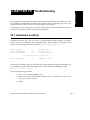
CHAPTER 10 Troubleshooting
10.1 Installation Conflicts . . . . . . . . . . . . . . . . . . . . . . . . . . . . . . . . . . . . . . . . . . . . . . . . . . . . 10 - 1
10.1.1 Resolving Installation Conflicts . . . . . . . . . . . . . . . . . . . . . . . . . . . . . . . . . . . 10 - 2
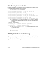
10.2 Adapter Hardware Troubleshooting . . . . . . . . . . . . . . . . . . . . . . . . . . . . . . . . . . . . . . . . 10 - 2
10.2.1 Check Self-Test (Automatically Performed) . . . . . . . . . . . . . . . . . . . . . . . . . . 10 - 4
10.2.2 Firmware Download (Automatically Performed) . . . . . . . . . . . . . . . . . . . . . . 10 - 4
10.2.3 Hardware Detected by Driver . . . . . . . . . . . . . . . . . . . . . . . . . . . . . . . . . . . . 10 - 5
10.2.4 Checking the Physical Link . . . . . . . . . . . . . . . . . . . . . . . . . . . . . . . . . . . . . . 10 - 6
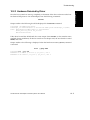
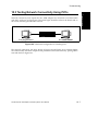
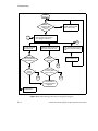
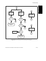
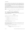
10.3 Testing Network Connectivity Using PVCs . . . . . . . . . . . . . . . . . . . . . . . . . . . . . . . . . . 10 - 7
10.3.1 Verifying the Outgoing ATM ARP Entry . . . . . . . . . . . . . . . . . . . . . . . . . . . . 10 - 10
10.3.2 adstat. . . . . . . . . . . . . . . . . . . . . . . . . . . . . . . . . . . . . . . . . . . . . . . . . . . . . . 10 - 11
10.3.2.1 No Cells Received by Remote End . . . . . . . . . . . . . . . . . . . . . . . . . . 10 - 11
10.3.2.2 Cells and VPI/VCI Errors Received by Remote . . . . . . . . . . . . . . . . . 10 - 12
10.3.2.3 Cells and AAL* Errors Received by Remote . . . . . . . . . . . . . . . . . . . 10 - 12
10.3.2.4 Cells and No Errors Received by Remote/Transmitting No Cells. . . . 10 - 12
10.3.2.5 Cells and No Errors Received by Remote/Transmitting Cells . . . . . . 10 - 12
ForeRunner® HE ATM Adapters for IRIX® Systems User’s Manual
TOC - 5
Table of Contents
10.4 LAN Emulation Troubleshooting . . . . . . . . . . . . . . . . . . . . . . . . . . . . . . . . . . . . . . . . . .10 - 13
10.4.1 Troubleshooting Procedures . . . . . . . . . . . . . . . . . . . . . . . . . . . . . . . . . . . . .10 - 13
10.4.1.1 Before Beginning. . . . . . . . . . . . . . . . . . . . . . . . . . . . . . . . . . . . . . . . .10 - 13
10.4.1.2 Is the ELAN state "Operational?" . . . . . . . . . . . . . . . . . . . . . . . . . . . .10 - 14
10.4.1.3 Is the ATM address assigned? . . . . . . . . . . . . . . . . . . . . . . . . . . . . . .10 - 14
10.4.1.4 Last Error in the elconfig show -configured command? . . . . . . . . . . . .10 - 15
10.5 Collecting Additional Information . . . . . . . . . . . . . . . . . . . . . . . . . . . . . . . . . . . . . . . . .10 - 17
10.5.1 Adapter Information . . . . . . . . . . . . . . . . . . . . . . . . . . . . . . . . . . . . . . . . . . .10 - 17
10.5.2 Switch Information . . . . . . . . . . . . . . . . . . . . . . . . . . . . . . . . . . . . . . . . . . . .10 - 20
APPENDIX A
A.1
A.2
APPENDIX B
B.1
B.2
D.2
D.3
Tunable Parameters
CPU to ATM Adapter Mapping. . . . . . . . . . . . . . . . . . . . . . . . . . . . . . . . . . . . . . . . . . .
TCP Performance . . . . . . . . . . . . . . . . . . . . . . . . . . . . . . . . . . . . . . . . . . . . . . . . . . . .
UDP Socket Buffer Overflows . . . . . . . . . . . . . . . . . . . . . . . . . . . . . . . . . . . . . . . . . . .
Tuning the HE622 . . . . . . . . . . . . . . . . . . . . . . . . . . . . . . . . . . . . . . . . . . . . . . . . . . . .
C.4.1
Enabling Interrupt Coalescing . . . . . . . . . . . . . . . . . . . . . . . . . . . . . . . . . . .
APPENDIX D
D.1
ATM Network Configurations
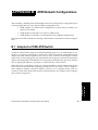
Adapter-to-FORE ATM Switch . . . . . . . . . . . . . . . . . . . . . . . . . . . . . . . . . . . . . . . . . . . B - 1
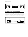
Adapter-to-Other Vendor’s Equipment. . . . . . . . . . . . . . . . . . . . . . . . . . . . . . . . . . . . . B - 2
APPENDIX C
C.1
C.2
C.3
C.4
PMD LED Indicators
LED Location . . . . . . . . . . . . . . . . . . . . . . . . . . . . . . . . . . . . . . . . . . . . . . . . . . . . . . . . A - 1
LED Descriptions. . . . . . . . . . . . . . . . . . . . . . . . . . . . . . . . . . . . . . . . . . . . . . . . . . . . . A - 1
C-1
C-2
C-2
C-3
C-3
Two-Node Origin200 and 2GB Octane Support
The Problem . . . . . . . . . . . . . . . . . . . . . . . . . . . . . . . . . . . . . . . . . . . . . . . . . . . . . . . .
D.1.1
Single Origin200 Systems . . . . . . . . . . . . . . . . . . . . . . . . . . . . . . . . . . . . . .
The Solution . . . . . . . . . . . . . . . . . . . . . . . . . . . . . . . . . . . . . . . . . . . . . . . . . . . . . . . .
Tunable Parameters . . . . . . . . . . . . . . . . . . . . . . . . . . . . . . . . . . . . . . . . . . . . . . . . . . .
D-1
D-2
D-3
D-3
Index
TOC - 6
ForeRunner® HE ATM Adapters for IRIX® Systems User’s Manual
List of Figures
CHAPTER 1
Figure 1.1
Figure 1.2
Figure 1.3
Figure 1.4
Figure 1.5
Introduction
Example ELAN . . . . . . . . . . . . . . . . . . . . . . . . . . . . . . . . . . . . . . . . . . . . . . . . 1 - 4
LANE Without MPOA. . . . . . . . . . . . . . . . . . . . . . . . . . . . . . . . . . . . . . . . . . . . 1 - 7
LANE With MPOA . . . . . . . . . . . . . . . . . . . . . . . . . . . . . . . . . . . . . . . . . . . . . . 1 - 9
MPOA Example Network . . . . . . . . . . . . . . . . . . . . . . . . . . . . . . . . . . . . . . . . 1 - 11
HE Series Adapters . . . . . . . . . . . . . . . . . . . . . . . . . . . . . . . . . . . . . . . . . . . . 1 - 15
CHAPTER 2
Hardware Installation
CHAPTER 3
Software Installation and Configuration
Figure 3.1
Figure 3.2
Figure 3.3
Figure 3.4
Figure 3.5
Figure 3.6
Figure 3.7
Figure 3.8
Figure 3.9
Figure 3.10
Figure 3.11
Figure 3.12
Figure 3.13
Figure 3.14
CHAPTER 4
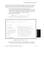
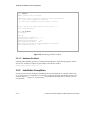
Software Installation Screen . . . . . . . . . . . . . . . . . . . . . . . . . . . . . . . . . . . . . . 3 - 3
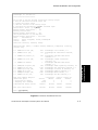
Software Installation Pick-List . . . . . . . . . . . . . . . . . . . . . . . . . . . . . . . . . . . . . 3 - 5
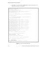
Software Installation Messages . . . . . . . . . . . . . . . . . . . . . . . . . . . . . . . . . . . . 3 - 6
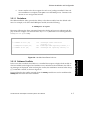
Modified Installation Pick-List . . . . . . . . . . . . . . . . . . . . . . . . . . . . . . . . . . . . . 3 - 7
Resolving Software Conflicts . . . . . . . . . . . . . . . . . . . . . . . . . . . . . . . . . . . . . . 3 - 8
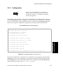
configure_atm Script Main Menu . . . . . . . . . . . . . . . . . . . . . . . . . . . . . . . . . . . 3 - 9
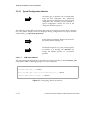
Configuring ATM Core Software . . . . . . . . . . . . . . . . . . . . . . . . . . . . . . . . . . 3 - 10
Configuring UNI Signalling . . . . . . . . . . . . . . . . . . . . . . . . . . . . . . . . . . . . . . 3 - 12
Configuring MPOA/LAN Emulation . . . . . . . . . . . . . . . . . . . . . . . . . . . . . . . . 3 - 15
Configuring LAppQoS . . . . . . . . . . . . . . . . . . . . . . . . . . . . . . . . . . . . . . . . . . 3 - 18
Configuring Classical IP . . . . . . . . . . . . . . . . . . . . . . . . . . . . . . . . . . . . . . . . 3 - 19
Configuring SPANS Signalling . . . . . . . . . . . . . . . . . . . . . . . . . . . . . . . . . . . . 3 - 20
Configuring FORE IP. . . . . . . . . . . . . . . . . . . . . . . . . . . . . . . . . . . . . . . . . . . 3 - 21
Configuring the HE Adapter. . . . . . . . . . . . . . . . . . . . . . . . . . . . . . . . . . . . . . 3 - 23
Network Interface Administration
Figure 4.1 Multi-homing Network Configuration . . . . . . . . . . . . . . . . . . . . . . . . . . . . . . . . 4 - 8
Figure 4.2 ATM Network with Access to Ethernet. . . . . . . . . . . . . . . . . . . . . . . . . . . . . . . 4 - 9
CHAPTER 5
Configuring FORE IP
Figure 5.1 IP Permanent Virtual Circuit . . . . . . . . . . . . . . . . . . . . . . . . . . . . . . . . . . . . . . 5 - 1
CHAPTER 6
Configuring Classical IP
Figure 6.1 Configuring a Third-Party Switch with ILMI Support . . . . . . . . . . . . . . . . . . . . 6 - 9
ForeRunner® HE ATM Adapters for IRIX® Systems User’s Manual
LOF - 7
List of Figures
Figure 6.2 Configuring a Third-Party Switch with RFC-1577 and No ILMI Support. . . . .6 - 10
CHAPTER 7
Figure 7.1
Figure 7.2
Figure 7.3
Figure 7.4
Figure 7.5
Figure 7.6
Figure 7.7
Figure 7.8
Figure 7.9
Figure 7.10
Figure 7.11
Figure 7.12
Figure 7.13
Figure 7.14
Figure 7.15
Figure 7.16
Figure 7.17
Figure 7.18
Configuring an ELAN
Basic Emulated LAN Interconnections . . . . . . . . . . . . . . . . . . . . . . . . . . . . . . .7 - 2
ELAN Operation . . . . . . . . . . . . . . . . . . . . . . . . . . . . . . . . . . . . . . . . . . . . . . . .7 - 5
Single Server LANE Services Model . . . . . . . . . . . . . . . . . . . . . . . . . . . . . . . .7 - 8
Broadcast IP-ARP Request . . . . . . . . . . . . . . . . . . . . . . . . . . . . . . . . . . . . . . .7 - 9
IP ARP Response Handling . . . . . . . . . . . . . . . . . . . . . . . . . . . . . . . . . . . . . . .7 - 9
Distributed LAN Emulation Model. . . . . . . . . . . . . . . . . . . . . . . . . . . . . . . . . .7 - 10
IP ARP Broadcast from LEC 1 to LEC 9. . . . . . . . . . . . . . . . . . . . . . . . . . . . .7 - 11
Re-distributing the Broadcast across DLE Peer Servers . . . . . . . . . . . . . . . .7 - 11
LE-ARP for Unknown Host Sent to Proxies and DLE Peer Servers . . . . . . . .7 - 12
LE-ARP Query Answered by One DLE Peer Server and Re-distributed . . . .7 - 12
LE-ARP Response Delivered and LEC 9 Contacts LEC 1 . . . . . . . . . . . . . . .7 - 13
ELAN with Single Server and Multiple Switches Connecting to Services . . .7 - 14
ELAN with Single Server and Remote Connection to Server . . . . . . . . . . . . .7 - 15
ELAN with Single Server in Operation . . . . . . . . . . . . . . . . . . . . . . . . . . . . . .7 - 15
Registrations on an ELAN with Multiple Servers . . . . . . . . . . . . . . . . . . . . . .7 - 16
ELAN with Multiple Servers in Operation . . . . . . . . . . . . . . . . . . . . . . . . . . . .7 - 17
Failure of One ELAN Server and the Recovery Process . . . . . . . . . . . . . . . .7 - 17
ELAN Re-established Using the Second Server . . . . . . . . . . . . . . . . . . . . . .7 - 18
CHAPTER 8
Additional Administration Information
CHAPTER 9
Software Interfaces
CHAPTER 10 Troubleshooting
Figure 10.1
Figure 10.2
Figure 10.3
Figure 10.4
APPENDIX A
Adapter Troubleshooting Flowchart . . . . . . . . . . . . . . . . . . . . . . . . . . . . . . . .10 - 3
Hardware Configuration for Checking PVCs. . . . . . . . . . . . . . . . . . . . . . . . . .10 - 7
Networking Connectivity Using PVCs (Page 1) . . . . . . . . . . . . . . . . . . . . . . .10 - 8
Networking Connectivity Using PVCs (Page 2) . . . . . . . . . . . . . . . . . . . . . . .10 - 9
PMD LED Indicators
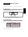
Figure A.1 SC Connector Face Plate Configuration. . . . . . . . . . . . . . . . . . . . . . . . . . . . . A - 1
APPENDIX B
ATM Network Configurations
Figure B.1 Minimum Configuration with UNI 3.0 or UNI 3.1 Signalling . . . . . . . . . . . . . . B - 2
Figure B.2 Adapter-to-Other Vendor Configuration . . . . . . . . . . . . . . . . . . . . . . . . . . . . . B - 2
LOF - 8
ForeRunner® HE ATM Adapters for IRIX® Systems User’s Manual
List of Figures
APPENDIX C
Tunable Parameters
APPENDIX D
Two-Node Origin200 and 2GB Octane Support
ForeRunner® HE ATM Adapters for IRIX® Systems User’s Manual
LOF - 9
List of Figures
LOF - 10
ForeRunner® HE ATM Adapters for IRIX® Systems User’s Manual
List of Tables
CHAPTER 1
Table 1.1
Table 1.2
Table 1.3
Table 1.4
Table 1.5
CHAPTER 2
Table 2.1
CHAPTER 3
Table 3.1
CHAPTER 4
Table 4.1
Introduction
Supported Platforms . . . . . . . . . . . . . . . . . . . . . . . . . . . . . . . . . . . . . . . . . . .
HE155 Adapter Specifications . . . . . . . . . . . . . . . . . . . . . . . . . . . . . . . . . . . .
HE622 Adapter Specifications . . . . . . . . . . . . . . . . . . . . . . . . . . . . . . . . . . . .
System Limitations . . . . . . . . . . . . . . . . . . . . . . . . . . . . . . . . . . . . . . . . . . . .
Fiber-Optic Specifications . . . . . . . . . . . . . . . . . . . . . . . . . . . . . . . . . . . . . . .
Hardware Installation
Related Silicon Graphics Manuals. . . . . . . . . . . . . . . . . . . . . . . . . . . . . . . . . . 2 - 1
Software Installation and Configuration
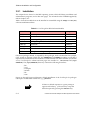
ForeThought for IRIX Software Modules . . . . . . . . . . . . . . . . . . . . . . . . . . . . . 3 - 2
Network Interface Administration
Default Interface Names . . . . . . . . . . . . . . . . . . . . . . . . . . . . . . . . . . . . . . . . . 4 - 1
CHAPTER 5
Configuring FORE IP
CHAPTER 6
Configuring Classical IP
CHAPTER 7
Configuring an ELAN
CHAPTER 8
Additional Administration Information
Table 8.1
CHAPTER 9
1 - 18
1 - 20
1 - 21
1 - 22
1 - 23
ForeThought 5.1 Administrative Programs and Manual Pages . . . . . . . . . . . . 8 - 2
Software Interfaces
CHAPTER 10 Troubleshooting
APPENDIX A
Table A.1
Table A.2
PMD LED Indicators
Transmit LED . . . . . . . . . . . . . . . . . . . . . . . . . . . . . . . . . . . . . . . . . . . . . . . . . . A - 1
Receive LED . . . . . . . . . . . . . . . . . . . . . . . . . . . . . . . . . . . . . . . . . . . . . . . . . . A - 2
APPENDIX B
ATM Network Configurations
APPENDIX C
Tunable Parameters
APPENDIX D
Two-Node Origin200 and 2GB Octane Support
ForeRunner® HE ATM Adapters for IRIX® Systems User’s Manual
LOT - 11
List of Tables
LOT - 12
ForeRunner® HE ATM Adapters for IRIX® Systems User’s Manual
Preface
Preface
This manual provides general product information, network configuration information and
information on software administration capabilities of the ForeRunner®HE ATM adapters, as
used with the IRIX 6.5 operating system, with the necessary information to install the adapter
and accompanying ForeThought 5.1 software. This manual was created for users with various
levels of experience. The procedures contained herein should be carefully read before attempting to perform the installation and configuration. If there are any questions or problems with
installation or configuration, please contact the Silicon Graphics Product Support.
Chapter Summaries
Chapter 1 - Introduction - Provides an overview of ATM, adapter hardware and software, and
general information to prepare for the installation of ForeRunner adapter.
Chapter 2 - Hardware Installation - Guides the user through the installation of the ForeRunner
adapters. Included are hardware installation instructions, how to test to verify the proper
installation, and product registration information.
Chapter 3 - Software Installation and Configuration - Contains the requirements and instructions for the installation and configuration of the adapter software for the IRIX operating system.
Chapter 4 - Network Interface Administration - Provides network configuration information
such as assigning an IP address, configuring a workstation as a multi-homed and/or ATMonly workstation, and the dynamic and static IP routing information for an ATM-only network.
Chapter 5 - Configuring FORE IP - Discusses how to configure the ForeRunner adapters in a
FORE IP network environment.
Chapter 6 - Configuring Classical IP - Discusses how to integrate ATM into legacy LANs.
Chapter 7 - Configuring an ELAN - Provides information on the methods for configuring
emulated LANs.
ForeRunner® HE ATM Adapters for IRIX® Systems User’s Manual
i
Preface
Chapter 8 - Additional Administration Information - Provides information on administration commands and on-line manual pages supplied with the ForeThought 5.1 software.
Chapter 9 - Software Interfaces - Provides information about the XTI programming interface
support that is provided with the ForeRunner adapter software.
Chapter 10 - Troubleshooting - Provides information about tests that can isolate and locate
possible problems.
Appendix A - PMD LED Indicators - Describes the physical and functional capabilities of the
PMD module LED indicators.
Appendix B - ATM Network Configurations - Contains examples of various physical network configurations using ForeRunner adapters.
Appendix C - Tunable Parameters - This appendix provides information that can be used to
better tune performance characteristics of ATM adapters running ForeThought 5.1 software.
Appendix D - Two-Node Origin200 and 2GB Octane Support - This appendix provides
information that can be used to configure and tune for peak performance two node Origin200
and 2GB Octane systems.
ii
ForeRunner® HE ATM Adapters for IRIX® Systems User’s Manual
Preface
Silicon Graphics Product Support
Preface
Silicon Graphics, Inc., provides a comprehensive product support and maintenance program
for its products. If you are in North America, and would like support for your Silicon Graphics-supported products, contact Silicon Graphics Product Support at 1-800-800-4SGI or your
authorized service provider. If you are outside North America, contact the Silicon Graphics
subsidiary or authorized distributor in your country.
ForeRunner® HE ATM Adapters for IRIX® Systems User’s Manual
iii
Preface
Typographical Styles
Throughout this manual, specific commands to be entered by the user appear on a separate
line in bold typeface. In addition, use of Enter or Return keys is represented as <Enter>. The
following example demonstrates this convention:
cd /usr <Enter>
Commands, menu items, or file names that appear within the text of this manual are represented in the following style: “...the atmarp command shows a user the current connections
to the adapter as well as the ATM address.”
As in the following example, any messages appearing on the screen during software installation or network interface administration appear in Courier font to distinguish them from the
rest of the text.
Save Configuration Information? [y]
iv
ForeRunner® HE ATM Adapters for IRIX® Systems User’s Manual
Preface
Important Information Indicators
Preface
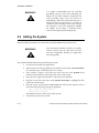
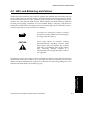
To call attention to safety and otherwise important information that must be reviewed to
insure correct and complete installation, as well as to avoid damage to the adapter or the system, FORE Systems utilizes the following WARNING/CAUTION/NOTE indicators.
WARNING statements contain information that is critical to the safety of the operator and/or
the system. Do not proceed beyond a WARNING statement until the indicated conditions are
fully understood or met. This information could prevent serious injury to the operator and
damage to the adapter, the system, or currently loaded software, and are indicated as:
WARNING!
Hazardous voltages are present. To lessen the
risk of electrical shock and danger to personal
health, follow the instructions carefully.
Information contained in CAUTION statements is important for proper installation/operation. Compliance with CAUTION statements can prevent possible equipment damage and/
or loss of data and are indicated as:
CAUTION
Damage to the equipment and/or software is
possible if these instructions are not followed.
Information contained in NOTE statements has been found important enough to be called to
the special attention of the operator and are set off from the text as follows:
NOTE
Steps 1, 3, and 5 are similar to the installation for
the computer type above. Review the previous
installation procedure before installation in the
particular model.
ForeRunner® HE ATM Adapters for IRIX® Systems User’s Manual
v
Preface
Safety Agency Compliance
This preface provides safety precautions to follow when installing a FORE Systems, Inc., product.
Safety Precautions
For personal protection, observe the following safety precautions when setting up the equipment:
•
Follow all warnings and instructions marked on the equipment.
•
Ensure that the voltage and frequency of the power source matches the voltage
and frequency inscribed on the equipment’s electrical rating label.
•
Never push objects of any kind through openings in the equipment. Dangerous
voltages may be present. Conductive foreign objects could produce a short circuit
that could cause fire, electric shock, or damage to the equipment.
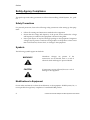
Symbols
The following symbols appear in this book.
WARNING!
Hazardous voltages are present. If the
instructions are not heeded, there is a risk of
electrical shock and danger to personal health.
CAUTION
If instructions are not followed, there is a risk of
damage to the equipment.
Modifications to Equipment
Do not make mechanical or electrical modifications to the equipment. FORE Systems, Inc., is
not responsible for regulatory compliance of a modified FORE product.
vi
ForeRunner® HE ATM Adapters for IRIX® Systems User’s Manual
CHAPTER 1
Introduction
This chapter provides an overview of the Asynchronous Transfer Mode (ATM) Standard, LAN
Emulation Over ATM (LANE), Multi-Protocol Over ATM (MPOA), and the following FORE
ForeRunner adapters:
•
HE155 and HE622 for the PCI bus
1.1 Overview of the ATM Standard
ATM is a communication architecture based on the switching of small fixed length packets of
data called cells. In ATM, all data is transferred in 53-byte cells. Each cell has a 5-byte header
that identifies the cell’s route through the network and 48-bytes containing user data. This
user data, in turn, carries any headers or trailers required by higher level protocols.
Perhaps the most important advantage offered by ATM, in addition to data transfer speed, is
its open-ended growth path. ATM is not locked into one physical medium or speed. The fixedsize ATM cell allows traffic from multiple sources (simultaneous video, audio, and data) to be
switched to multiple destinations by fast ATM switches. For example, a ForeRunner ASX-1000
ATM Switch can connect up to 96 users and has an aggregate capacity of 10 gigabits per second. Larger LANs can be built by interconnecting multiple ForeRunner ATM switches.
1.2 Overview of LANE/MPOA
FORE System’s ForeThought 5.1 software is compliant with the ATM Forum’s LAN Emulation
Over ATM Version 2.0 specification. LAN Emulation (LANE) allows higher level protocols and
LAN applications to interoperate, without modifications, with an ATM network.
ForeRunner® HE ATM Adapters for IRIX® Systems User’s Manual
1-1
Introduction
Hardware and software requirements and the contents of the adapter packages are also discussed.
Introduction
The LANE components, running on the ATM network, interact to emulate an Ethernet or
Token Ring LAN. This emulated Ethernet or Token Ring LAN is called an emulated LAN
(ELAN). The ELAN components resolve MAC addresses to ATM addresses, replace the connectionless operation of legacy LANs with point-to-point connections, and provide broadcast
and multicast services. The ELAN consists of a LANE/MPOA Client (LEC/MPC) running on
each host in the ELAN, and the following LANE Services:
•
the LAN Emulation Server (LES)
•
the Broadcast and Unknown Server (BUS)
•
the LAN Emulation Configuration Server (LECS)
In ForeThought 5.1, the LANE services may operate on a FORE Systems switch, PowerHub 7000,
or Solaris workstation. ForeThought 5.1 introduces support for Distributed LAN Emulation
(DLE) which provides load-sharing and improved fault-tolerance within an ELAN.
LANE also is the foundation on which MPOA is built.
1.3 LANE Primer
LAN Emulation (LANE) is the foundation on which Multi-Protocol Over ATM (MPOA) is
built. Therefore, before presenting an explanation of MPOA, an understanding of LANE components and their operation in an emulated LAN (ELAN) is needed.
1.3.1
LANE Components
An ELAN includes the following components:
1-2
LANE/MPOA Client (LEC/MPC)
The LEC/MPC can wear two different “hats”. When
wearing its LEC “hat,” it simply communicates with
other ELAN components (the LES and BUS) to
resolve MAC addresses into ATM addresses. When it
puts on its MPC “hat,” the additional function of the
LEC/MPC in an MPOA-aware network is to source
and sink internetwork shortcuts.
LAN Emulation
Configuration Server (LECS)
Runs on a Solaris workstation or a FORE Systems
switch. Maintains information about all ELANs
within the administrative domain. When the LEC/
MPC successfully communicates with the LECS, the
LECS provides a list of ELANs which the LEC/MPC
can join. The LECS may be configured with various
MPOA parameters. LEC/MPCs that connect to
LANE/MPOA services through an MPOA-aware
ForeRunner® HE ATM Adapters for IRIX® Systems User’s Manual
Introduction
LECS are configured with these centrally-supplied
MPOA parameters. LEC/MPCs that connect through
an LECS that does not contain MPOA parameters
still performs flow analysis and attempts inter-ELAN
shortcuts according to user-editable or factorydefault settings.
Runs on a PowerHub 7000, a ForeRunner switch, or a
Solaris workstation. Maintains information about the
LEC/MPCs within a single ELAN and performs
address resolution. The LES can be configured to
support or disable MPOA operation in an ELAN.
The LES accepts MPOA parameters from registering
LEC/MPCs, and distributes MPOA parameters to
LEC/MPCs in response to queries. (This is the
mechanism used by LEC/MPCs to determine
whether routers in the ELAN are MPOA-aware).
Broadcast and Unknown Server
(BUS)
Runs on a PowerHub 7000, a ForeRunner switch, or a
Solaris workstation. Provides services within a single
ELAN allowing broadcasts, multicast, and unknown
unicasts. The BUS is MPOA-ignorant.
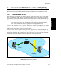
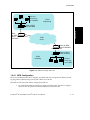
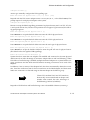
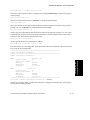
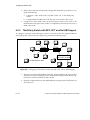
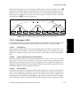
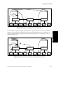
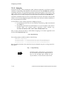
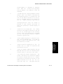
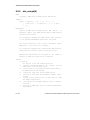
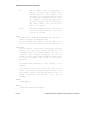
1.3.2
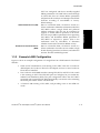
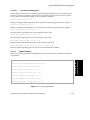
Example LANE Configuration
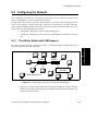
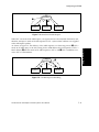
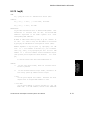
Figure 1.1 shows an example configuration of a single ELAN in a FORE network. The ELAN
includes:
•
UNIX and PC Workstations, each running a LEC/MPC. Each has a ForeRunner
ATM adapter, the ForeRunner driver for the adapter, and one or more ForeRunner
ELAN drivers installed.
•
Two ForeRunner ASX-200BX switches running LESs, BUSs, and LECs. Each switch
is also running an LECS. The LES/BUS pairs are configured as peers under Distributed LAN Emulation (DLE). The peer configuration allows the LEC/MPCs
associated with a particular LES/BUS automatically to reconnect to the remaining
functional peer if their “home” LES/BUS fails.
•
A Powerhub 7000 running a LEC/MPC, and providing access to non-ATM networks.
ForeRunner® HE ATM Adapters for IRIX® Systems User’s Manual
1-3
Introduction
LAN Emulation Server (LES)
Introduction
ATM
UNIX
UNIX
UNIX
ASX-200BX
Each PC/
UNIX Workstation
runs a
LEC/MPC
PC
PC
PC
ASX-200BX
Runs a LECS,
LES/BUS, and/or
LEC
PowerHub 7000
Runs a
LEC/MPC
Runs a LECS,
LES/BUS, and/or
LEC
Fast Ethernet
FDDI
Ethernet
Figure 1.1 - Example ELAN
1.3.2.1 Initialization Process
NOTE
1-4
This section discusses the general aspects of
LANE configuration. The specific capabilities of
each FORE adapter is dependent on the
operating system of the parent platform. Refer to
Chapter 7, Configuring an ELAN for more detailed
information.
ForeRunner® HE ATM Adapters for IRIX® Systems User’s Manual
Introduction
Each LEC/MPC goes through the following process when it starts up:
1.
The LEC/MPC obtains its own ATM address via address registration. Optionally,
the ATM address can be manually specified.
2.
The LEC/MPC establishes a connection to a LECS using an address obtained via
ILMI, a well-known address, or the Permanent Virtual Circuit (0,17). Optionally,
the LECS address can be manually specified.
3.
The LEC/MPC requests the information needed to join a specified ELAN or the
default ELAN. The LECS has information about available ELANs, what ELANs
each LEC/MPC can join, and which ELAN the LEC/MPC should attempt to join
first.
4.
The LEC/MPC contacts the LES associated with the ELAN it wants to join and registers its MAC-ATM address pair. It also contacts the BUS associated with the
ELAN. At this point, the LEC/MPC and the LES have the information required to
allow this host to communicate with other hosts on the ELAN as if it were an Ethernet (or Token-Ring) network. Refer to the following section for a description of
how the LEC/MPC connects to other hosts on the ELAN.
1.3.2.2 Connection Process
To send packets to another host on the ELAN:
1.
The LEC/MPC calls the LES to map the MAC destination address into an ATM
address. (The LES maintains a mapping table of the address of all LEC/MPCs on
the ELAN.)
2.
If the LES finds an entry in its table for the destination MAC address, it returns the
destination ATM address to the LEC/MPC.
3.
The LEC/MPC then opens up a point-to-point ATM connection to the destination
host to send the packet.
1.3.2.3 Multicast and Broadcast Packets
The LEC/MPC sends outgoing multicast and broadcast packets to the BUS which uses a
point-to-multipoint connection to send the packets to multiple ATM addresses in the ELAN.
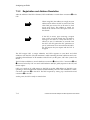
1.3.2.4 Accessing Fast Ethernet and FDDI Networks
Note that the diagram in Figure 1.1 shows dotted lines from the PowerHub 7000 to the Fast
Ethernet and FDDI networks. This is because the PowerHub does not use bridging to reach
these networks but must route to them.
ForeRunner® HE ATM Adapters for IRIX® Systems User’s Manual
1-5
Introduction
If a LECS is not available, or if not being used, manually specify the information
required to join a specific ELAN.
Introduction
1.3.2.5 Multiple ELANs
It is possible to set up more than one ELAN in a FORE network. For each new ELAN, another
LES/BUS instance must be configured for that LAN. On the access devices, bridge groups
must be used to associate physical ports with ELANs on the ATM side.
An end station in the ELAN with a ForeRunner adapter can connect to up to 16 ELANs simultaneously.
1.3.2.6 Distributed LAN Emulation
To ensure that a single LES/BUS failure does not bring down an entire ELAN, ForeThought 5.1
introduces Distributed LAN Emulation (DLE). DLE allows the LES/BUS functions to be distributed among multiple interconnected LES/BUS instances called peers. In the example
ELAN shown in Figure 1.1, the two LES/BUS pairs running in the switches function as peers
in the same ELAN. The LEC/MPCs are distributed such that they are not all connected to the
same server. With this arrangement, should one of the peer servers fail, the clients connected
to the remaining server continue to maintain connectivity; while the clients that were connected to the failed server automatically reestablish connectivity to the ELAN within 60 seconds.
1.3.2.7 Automatic ELAN Selection
To simplify configuration of the ELAN, ForeThought 5.1 allows a host to join an ELAN without
specifying an ELAN name. If the LECS has been configured to provide the required information, and an ELAN name to join was not manually specified when the ELAN driver was configured, the host initially attempts to join the ELAN specified by the LECS. The host
successfully joins the ELAN if the LECS is available, the proper LES address for the ELAN has
been specified in the LECS, and the LES and BUS are available.
1.3.2.8 Intelligent BUS
This feature reduces broadcast traffic by using the MAC address information in the LES.
When an intelligent BUS receives a unicast frame, the BUS first checks the LES’s mapping
table to see if the MAC address is registered there. If it is, the BUS routes the frame directly to
the destination, instead of broadcasting.
1-6
ForeRunner® HE ATM Adapters for IRIX® Systems User’s Manual
Introduction
1.4 Introduction to Multi-Protocol Over ATM (MPOA)
Multi-Protocol Over ATM (MPOA) builds upon the foundation of LAN Emulation (LANE).
1.4.1
LANE Without MPOA
ATM networks co-exist with and support network applications which may not be ATMaware. Consequently, ATM protocols are needed to monitor legacy network protocol (IP, IPX,
Appletalk, etc.) packets and perform translation into ATM cells and circuits. This monitoring
and translation can be performed in one of the following ways:
in a host protocol stack after packet construction and before packet transmission
•
in a LAN-to-ATM edge device as packets move through the network
LANE is one example of such a protocol. It resolves datalink layer addresses into ATM
addresses and establishes circuits to the destination addresses. Network addresses within a
subnet can be learned using LANE’s broadcast support.
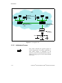
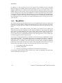
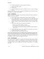
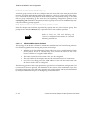
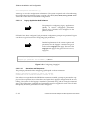
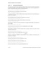
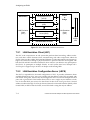
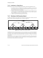
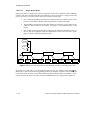
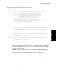
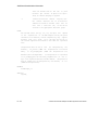
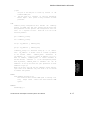
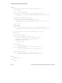
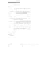
However, LANE relies on physical routers to deliver packets across subnets (see Figure 1.2).
Because routers must examine – and modify – every packet, ATM cells must be reassembled
into packets, modified, and re-segmented at every router hop. This process imposes significant
transmission delays between the source and destination of the network traffic.
Router
ATM Cloud
E LAN
engineering
E LAN
marketing
Figure 1.2 - LANE Without MPOA
ForeRunner® HE ATM Adapters for IRIX® Systems User’s Manual
1-7
Introduction
•
Introduction
In addition to LANE, protocols such as IP can operate over an ATM network via the IETF
Internetworking Over NBMA Networks (ION) Working Group’s Next Hop Resolution Protocol
(NHRP). NHRP allows the ATM network to be divided into Logical IP Subnets (LISs). Using
NHRP, routers are still required to interconnect these subnets; but NHRP permits intermediate
routers to be bypassed on the data path. NHRP allows entities called Next Hop Clients (NHCs)
to send queries between different subnets. These queries are propagated using Next Hop Servers (NHSs) via paths found using standard routing protocols. Consequently, NHRP enables
the establishment of VCC data paths across subnet boundaries without requiring physical routers
in the data path.
1.4.2
Why MPOA?
The ATM Forum developed the Multi-Protocol over ATM (MPOA) specification to address the
limitations of LAN Emulation. MPOA extends ATM support of legacy networks into the network layer. The main objective of MPOA is the efficient transfer of unicast data between subnet(s).
MPOA introduces LANE/MPOA Clients (LEC/MPCs) and MPOA Servers (MPSs) and
defines the protocols that are required for LEC/MPCs and MPSs to communicate. LEC/MPCs
issue queries for ATM addresses, and receive replies from the MPS using these protocols.
MPOA also maintains interoperability with the existing infrastructure of routers. MPOA Servers use routers that run standard Internetwork Layer routing protocols such as OSPF, thus
providing integration with existing networks.
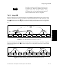
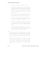
ForeThought 5.1 implements MPOA for IP traffic. It does this by adding capabilities to LANE,
not by replacing LANE. LANE/MPOA client drivers are extended LANE drivers. When handling traffic within the same ELAN and subnet, they function like LECs. However, when handling traffic that crosses subnets, LEC/MPCs initially work with MPSs to use MPS-established
hop-by-hop circuits. Then, for traffic flows that exceed configurable limits, shortcut circuits are
built that allow the traffic to traverse the route without the necessity of the router(s):
•
reassembling packets from ATM cells
•
modifying the packets
•
and then re-segmenting the packets for transmission to the next hop.
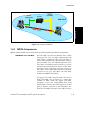
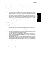
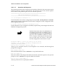
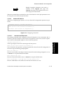
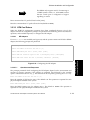
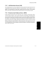
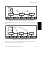
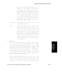
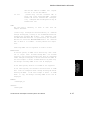
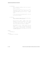
Consequently, traffic flowing through a shortcut VCC moves at essentially wire speed from
source to destination (see Figure 1.3).
1-8
ForeRunner® HE ATM Adapters for IRIX® Systems User’s Manual
Introduction
E LAN
engineering
R outer
E LAN
marketing
ATM Cloud
Introduction
S hor tcu
t VCC
Figure 1.3 - LANE With MPOA
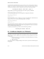
1.4.3
MPOA Components
MPOA requires LANE services for both ELAN traffic handling and MPOA configuration.
LANE/MPOA Client (LEC/MPC)
The LEC/MPC can wear two different “hats”. When
wearing its LEC “hat,” it simply communicates with
other ELAN components (the LES and BUS) to
resolve MAC addresses into ATM addresses. When it
puts on its MPC “hat,” the additional function of the
LEC/MPC in an MPOA-aware network is to source
and sink internetwork shortcut circuits. A LEC/MPC
that is the source of a shortcut is known as an ingress
LEC/MPC. A LEC/MPC that is the sink of a shortcut
is known as an egress LEC/MPC. The LEC/MPC
includes an NHRP Client (NHC).
An ingress LEC/MPC monitors traffic flow that is
being forwarded over an ELAN to a router that
contains an MPS. When the ingress LEC/MPC
recognizes a flow rate (configurable) that could
benefit from a shortcut (and thus bypass the routed
path), it requests a shortcut to the destination. If a
shortcut is available, the ingress LEC/MPC sets up a
ForeRunner® HE ATM Adapters for IRIX® Systems User’s Manual
1-9
Introduction
shortcut VCC, and forwards
destination over the shortcut.
traffic
for
the
An egress LEC/MPC receives internetwork traffic
from other LEC/MPCs to be forwarded to its local
interfaces/users. For traffic received over a shortcut,
the egress LEC/MPC adds the appropriate
encapsulation and forwards them via a LAN
interface (that may be a bridge port, an internal host
stack, etc.).
MPOA Server (MPS)
An MPS includes an NHRP Server (NHS) and is the
logical component of a router that provides
internetwork layer forwarding information to LEC/
MPCs. The MPS answers MPOA queries from
ingress LEC/MPCs and provides encapsulation
information to egress LEC/MPCs.
The MPS also converts between MPOA requests and
replies, and NHRP requests and replies, on behalf of
LEC/MPCs.
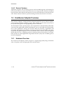
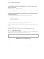
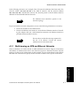
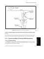
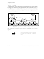
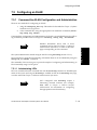
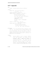
1.4.4
MPOA Example
The following are the basic requirements for establishing a shortcut across an MPOA-enabled
network:
•
there must be LEC/MPCs at each end of the network between which a shortcut is
desired.
•
the local router interface at each end must be running an MPS.
•
a Next Hop Resolution Protocol (NHRP) path must exist between MPSs.
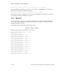
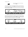
The following example illustrates a typical ATM network that allows MPOA shortcuts to be
employed.
1 - 10
ForeRunner® HE ATM Adapters for IRIX® Systems User’s Manual
Introduction
UNIX
UNIX
Each of
these runs
UNIX a LEC/MPC
ELAN
engineering
Runs a LECS,
ASX-200BX LES, and BUS
Introduction
Runs
an MPS
and a Powerhub 7000
LEC/MPC
ATM
Cloud
Runs an MPS
and a LEC/MPC
Powerhub 7000
Runs a LECS,
ASX-200BX LES, and BUS
ELAN
marketing
PC
PC
PC
Each of
these runs
a LEC/MPC
Figure 1.4 - MPOA Example Network
1.4.4.1 MPS Configuration
The network administrator must configure each MPS with the site-specific IP address matching the gateway address being used by LEC/MPCs in its ELAN.
The MPS on each PowerHub 7000 is configured as follows:
1.
For each LANE/MPOA virtual port, specify an ELAN name. The LECS configuration must also be updated to allow the MPS to join these ELANs.
ForeRunner® HE ATM Adapters for IRIX® Systems User’s Manual
1 - 11
Introduction
2.
For each LANE/MPOA virtual port, specify an IP address.
3.
Enable LANE/MPOA support.
4.
Enable routing.
5.
Save the configuration and reboot the MPS if necessary to make the changes
effective.
Router table information need not be configured. The MPS gathers this information through
routing protocol exchanges with other MPS’s.
1.4.4.2 Initialization
When its host boots, each LEC/MPC automatically goes through the following sequence to
establish a connection to the MPS.
1.
The LEC/MPC registers via ILMI with the switch to which it is attached.
2.
The LEC/MPC connects to an LECS to which it sends its own ATM address and
the name of the ELAN it wishes to join (the ELAN name is an empty string unless
the LEC/MPC has been site-configured with an ELAN name). The LEC/MPC also
supplies a LANE 1.0 compliant parameter identifying itself as an MPOA-aware
client.
3.
Next, the LEC/MPC receives the following from the LECS:
-
the name of the ELAN to which it is assigned
-
the ATM address of the LES for the ELAN it is joining
-
the parameters containing the flow detection and shortcut establishment policies it is to use
4.
The LEC/MPC then connects to its assigned LES, and provides the LES with a
parameter identifying itself as MPOA-aware.
5.
Finally, the LEC/MPC connects to the ELAN’s BUS.
Once the LANE/MPOA connections are established, third-party network-layer protocol drivers on the host can establish network-layer connectivity. The methods these upper-layer drivers use to determine host IP addresses, default gateway, and backup gateway addresses vary
depending on the third-party product. The LANE/MPOA driver itself permits these drivers
to use BOOTP or DHCP to obtain IP configuration information.
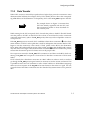
1.4.4.3 Flow Analysis
On a LEC/MPC’s host or edge device, IP packets with destinations within the host’s subnet
are sent using LANE 1.0 methods; i.e., the client puts on its LEC “hat” and works directly with
its ELAN’s services to connect with local destinations. Packets destined for remote subnets
cause the LEC/MPC to put on its MPC “hat”. This client is then referred to as an “ingress
LEC/MPC”.
1 - 12
ForeRunner® HE ATM Adapters for IRIX® Systems User’s Manual
Introduction
Ingress LEC/MPCs associate destination IP addresses with shortcut circuits. Ingress LEC/
MPCs use configurable parameters called flow descriptors to determine whether and when to
trigger creation of shortcut circuits. The ingress LEC/MPC also monitors the most recent use
of a shortcut circuit to determine when to tear down the shortcut. Specifically, when an ingress
LEC/MPC sends a packet:
If a shortcut circuit already exists to the IP destination, the LEC/MPC sends the
packet over this circuit.
2.
If no shortcut circuit exists, the LEC/MPC determines whether shortcuts to this IP
address are allowed. If shortcuts to the destination IP address are not allowed, the
LEC/MPC sends the packet to the gateway router.
3.
If no shortcut circuits exist, and shortcuts to the IP address are allowed, the LEC/
MPC determines if the packet traffic flow exceeds the shortcut enable trigger value
(set by the flow descriptors) for the destination IP address’s flow. If the flow
exceeds the trigger value, the LEC/MPC tries to establish a shortcut circuit to the
destination LEC/MPC (called the egress LEC/MPC). If the flow does not exceed
the trigger value, the ingress LEC/MPC simply sends the packet traffic to the gateway router.
1.4.4.4 Making a Shortcut
When the ingress LEC/MPC determines that the packet traffic flow exceeds the shortcutenable trigger value, the ingress LEC/MPC tries to establish a shortcut circuit to the egress
LEC/MPC. The following describes how a shortcut is set-up:
1.
The ingress LEC/MPC initiates the shortcut creation process by sending a request,
called a next hop resolution protocol (NHRP) request, to the MPS it uses as a gateway router (this MPS is called the ingress MPS). This NHRP request includes the
destination’s IP address and asks for the corresponding ATM destination address.
2.
This request is passed along hop-by-hop until it reaches the final MPS (called the
egress MPS) on the route to the destination IP address.
3.
The egress MPS looks up the ATM address corresponding to the destination IP
address, and returns the destination ATM address in a NHRP response hop-byhop to the ingress LEC/MPC.
4.
When the ingress LEC/MPC receives the NHRP response containing the destination’s ATM address, it first checks if a shortcut circuit to that ATM address already
exists. If a shortcut circuit to that address already exists, it sends the packets via the
existing shortcut circuit. If no shortcut circuit exists it opens a new shortcut circuit
and begins sending packets over it to the destination.
ForeRunner® HE ATM Adapters for IRIX® Systems User’s Manual
1 - 13
Introduction
1.
Introduction
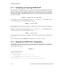
1.4.4.5 Shortcut Teardown
Application programs and networking protocol stacks are MPOA-ignorant and therefore do
not tear down shortcut circuits when the shortcut is no longer needed. Therefore the MPOA
layer itself tears down seldom-used shortcuts to avoid circuit exhaustion in the client and network. When a shortcut is idle for a period exceeding a set limit, the shortcut is torn down.
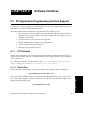
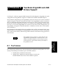
1.5 ForeRunner Adapter Overview
The ForeRunner adapter is a high performance adapter designed for use in a Silicon Graphicssystem running the IRIX 6.5 operating system. These adapters provide ATM connectivity for
host systems and supports evolving signalling and AAL standards.
The HE adapters feature special-purpose AAL5 Segmentation and Reassembly (SAR) hardware and scatter-gather DMA. With the HE adapters, users can add ATM networking capabilities to their applications, leaving the low-level ATM cell processing, segmentation and
reassembly, and signalling to the adapter’s hardware and device driver. In addition, the adapters provide transparent support for TCP/IP, Switched Virtual Circuits (SVCs) through the
SPANS and UNI 3.0 or 3.1 signalling protocols, Permanent Virtual Circuits (PVCs), LAN Emulation (LANE), an ATM Applications Programmer Interface (API), and an SNMP agent for
network management.
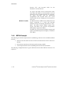
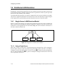
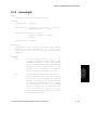
1.5.1
Hardware Overview
The ForeRunner HE adapters, shown in Figure 1.5, support high-quality image, full-motion
video, CD-quality audio, and high speed data communications.
1 - 14
ForeRunner® HE ATM Adapters for IRIX® Systems User’s Manual
Introduction
HE155
Requires 33 or 66 MHz PCI Bus Slot
Available with SC Connectors
Supports OC-3 Multi-Mode Fiber
Introduction
HE622
Requires 33 or 66 MHz PCI Bus Slot
Available with SC Connectors
Supports OC-12 Multi-Mode Fiber
Figure 1.5 - HE Series Adapters
ATM networking capabilities can be added to applications, leaving the low-level ATM cell
processing, segmentation and reassembly, and signalling to the adapter hardware and device
driver.
1.6 Software Overview
ForeRunner adapters use ForeThought’s market-proven support for TCP/IP protocols, allowing
existing applications to operate with no modifications. Major advantages include high-performance network throughput delivered to applications, and the flexibility for future upgrades.
The driver software implements:
•
SPANS Switched Virtual Circuits (SVC) signalling protocol that provides applications with end-to-end ATM connectivity including on-demand access to ForeRunner ATM switch multicast functions.
ForeRunner® HE ATM Adapters for IRIX® Systems User’s Manual
1 - 15
Introduction
1.6.1
•
ATM Forum-compliant Simple Network Management Protocol (SNMP) Management Information Base (MIB) which can be accessed by any SNMP network management system.
•
Supports UNI 3.0 and UNI 3.1 signalling standards.
•
Compliant with ATM Forum LAN Emulation over ATM, Version 2.0.
•
XTI API library, supplied with the adapter, offers applications access to unique
features of ATM such as guaranteed bandwidth reservation, per-connection selection of AAL0 (null), 3/4 or 5 and multicasting with dynamic addition and deletion of recipients.
Advanced Cell Processor Architecture
The Advanced Cell Processor Architecture provides optimized on-board cell processing functions including segmentation and reassembly (SAR). The software device driver provides a
high-performance packet-level interface to the cell-processing engine. The driver identifies the
data packets to be communicated over ATM; the cell-processing engine does the rest.
1 - 16
ForeRunner® HE ATM Adapters for IRIX® Systems User’s Manual
Introduction
1.6.2
Software Features
The 5.1 release of ForeThought software supports the ATM Forum LAN Emulation Over ATM,
Version 2.0 standard. The particular features supported include:
•
LAN Emulation Clients
•
Multiple Virtual LANs
•
Ethernet emulation
•
Multi-Protocol Over ATM
Additional software features include:
Distributed LAN Emulation
•
FORE IP load balancing
•
FORE IP automatic failover
•
Support for UNI 3.0 and 3.1 signalling
•
Support for Classical IP
•
UNI load balancing
•
UNI automatic failover
•
XTI API
Introduction
•
Each of these features is detailed in the appropriate chapters throughout this manual.
ForeRunner® HE ATM Adapters for IRIX® Systems User’s Manual
1 - 17
Introduction
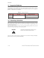
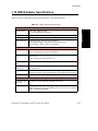
1.7 Supported Platforms
The HE adapters can be installed in any of the supported platforms listed in Table 1.1. Refer to
the IRIX® ATM ForeThought® 5.1 Release Notes for detailed information as to the supported
platforms, configurations, and limitations.
Table 1.1 - Supported Platforms
Adapter
HE155
Bus Type
Supported Platforms
Any available 33 or 66MHz PCI slot. Octane, O2, Origin200, Origin2000, and
Onyx2
HE622
Origin200, Origin2000, and Onyx2
1.8 Unpacking Information
Before unpacking the adapter, inspect the package for any damage that may have occurred
during shipping. If the package shows any signs of external damage or rough handling, notify
the carrier’s representative.
When unpacking the adapter, be sure to keep all original packing materials. They may be
needed for storing, transporting, or returning the product.
CAUTION
All products returned under warranty, must be
packed in their original packing materials.
Verify the package contents against the shipping list. If any items are missing or damaged,
please contact your service provider immediately.
1 - 18
ForeRunner® HE ATM Adapters for IRIX® Systems User’s Manual
Introduction
CAUTION
The ForeRunner adapter contains static-sensitive
devices. Keep the adapter in its protective bag
until installation. Electronic components are
subject to damage from even small amounts of
static discharge. Therefore, be sure to have the
equipment properly grounded. Be sure to use an
anti-static grounding strap and properly ground
the equipment when installing the adapter.
Introduction
ForeRunner® HE ATM Adapters for IRIX® Systems User’s Manual
1 - 19
Introduction
1.9 HE155 Adapter Specifications
Table 1.2 lists the capabilities and physical parameters of the HE155 adapter.
Table 1.2 - HE155 Adapter Specifications
Hardware
ATM Support
UBR, CBR, VBR and ABR
OC-3c (155 Mbps) full-duplex
Memory
2 Mbytes Synchronous DRAM
DMA Support
384 bytes (write), 768 bytes (read) Maximum Burst Size
Environmental
Operating Temp: 0° to 40° C (to 10,000 ft.)
Operating Humidity: 20 to 80% RH non-condensing
Storage Temp: -40° to +70° C (to 30,000 ft.)
Architecture
PCI Bus
PCI 2.1, 33 MHz, 32-bit addressing, 32 or 64 bit data
3.3 or 5V Single slot PCI short form factor.
ATM Support
ForeThought software including, MPOA, LANE 1.0/2.0 and CLIP
(RFC1577).
AAL5, AAL1 (via AAL0) UNI 3.0/3.1
Power Requirement
12 watts
Cabling and
Connectors
Duplex 62.5/125µ multi-mode fiber (2,000 meters max, 10 dB loss);
SC connectors
Host Interface
Full bus mastering, dynamic burst sizing, multiple programming
interrupts, receive queue prioritization, TCP checksum calculation.
Memory
2 Mbytes Synchronous DRAM; Supports 4K VCs
Compliance
Emissions and
Electrical
UL1950/CSA 950, EN60950, EN60825, IEC 825.1
Compliance
IEC 825.2
EMI: FCC Part 15, Class A, EN55022 Class A, VCCI Class 1, TS016
EMC: EN50082-1, EN50022
1 - 20
ForeRunner® HE ATM Adapters for IRIX® Systems User’s Manual
Introduction
1.10 HE622 Adapter Specifications
Table 1.3 lists the capabilities and physical parameters of the HE622 adapter.
Table 1.3 - HE622 Adapter Specifications
Hardware
UBR, CBR, VBR and ABR
OC-12c (622 Mbps) full-duplex
Memory
2 Mbytes Synchronous DRAM
DMA Support
384 bytes (write), 1536 bytes (read) Maximum Burst Size
Environmental
Operating Temp: 0° to 40° C (to 10,000 ft.)
Operating Humidity: 20 to 80% RH non-condensing
Storage Temp: -40° to +70° C (to 30,000 ft.)
Introduction
ATM Support
Architecture
PCI Bus
PCI 2.1, 33/66 MHz, 32-bit addressing, 32 or 64 bit data
3.3 or 5V Single slot PCI short form factor.
ATM Support
ForeThought software including, MPOA, LANE 1.0/2.0 and CLIP
(RFC1577).
AAL5, AAL1 (via AAL0) UNI 3.0/3.1
Power Requirement
12 watts
Cabling and
Connectors
Duplex 62.5/125µ multi-mode fiber (2,000 meters max, 10 dB loss);
SC connectors
Host Interface
Full bus mastering, dynamic burst sizing, multiple programming
interrupts, receive queue prioritization, TCP checksum calculation.
Memory
2 Mbytes Synchronous DRAM; Supports 4K VCs
Compliance
Emissions and
Electrical
UL1950/CSA 950, EN60950, EN60825, IEC 825.1
Compliance
IEC 825.2
EMI: FCC Part 15, Class A, EN55022 Class A, VCCI Class 1, TS016
EMC: EN50082-1, EN50022
ForeRunner® HE ATM Adapters for IRIX® Systems User’s Manual
1 - 21
Introduction
Table 1.4 - System Limitations
Description
Limiting Value
Maximum number of streams open
255
Maximum number of connections per adapter
4096
Number of LEC/MPCs supported per adapter
16 (maximum)
Number of ELANs supported
16 (maximum)
Number of DLE LES/BUS peers per ELAN
10 (maximum)
Number of clients supported by each LES/BUS
100 (maximum)
Maximum MTU size
65535 bytes (varies with selected protocol)
Incoming/outgoing (receive/send) VPI support
12-bits available for VPI/VCI
1 - 22
ForeRunner® HE ATM Adapters for IRIX® Systems User’s Manual
Introduction
1.11 Cable Specifications
The HE155 and HE622 adapters are available with a Multi-Mode Fiber (MMF) interface. Table
1.5 lists the fiber optic cabling specifications for MMF interfaces.
Table 1.5 - Fiber-Optic Specifications
Description
Specification
SC
Core Diameter
62.5 µm
Fiber Diameter
125 µm
Wavelength
1310 nm
Loss characteristic
~0.5 dB/km
Power Budget
11 dB1
Maximum run
approximately 2 km
Transmit Power
-19 dBm (minimum)
Receive Power
-30 dBm (minimum)
1.
Introduction
Connector Style
If a 50 µm core fiber is used, derate the power budget by 4dB.
ForeRunner® HE ATM Adapters for IRIX® Systems User’s Manual
1 - 23
Introduction
1 - 24
ForeRunner® HE ATM Adapters for IRIX® Systems User’s Manual
CHAPTER 2
Hardware Installation
This section is designed to assist in the installation of the adapter in a Silicon Graphics workstation. This chapter also contains handling and registration information. Please read all information carefully before attempting the installation.
2.1 General Installation Procedures
Installation of the adapter is a simple procedure and differs slightly for the various systems.
Refer to the appropriate manual listed in Table 2.1 for installation procedures related to the
appropriate platform type.
Hardware Installation
NOTE
Only SGI trained System Support Engineers (SSE’s)
are qualified to install, remove or replace XIO/PCI
boards.
Table 2.1 - Related Silicon Graphics Manuals
Platform
Origin2000
(Deskside
mount)
Part Number
Refer To
Onyx2 Origin2000 and Onyx2 Deskside 108-0155-004
Rack- and Rackmount Installation
Instructions
Chapter 6
O2 Workstation Hardware Ref- 007-3275-003
erence Manual
Chapter 2
Origin200 and Origin200 Origin200
and
Origin200 007-3708-001
GIGAchannel
GIGAchannel
Maintenance
Guide
Chapter 2
OCTANE
Chapter 4
O2
and
and
Manual Title
OCTANE Workstation Owner’s 007-3435-002
Guide
ForeRunner® HE ATM Adapters for IRIX® Systems User’s Manual
2-1
Hardware Installation
WARNING!
It is highly recommended that the included
grounding strap be used when handling the
adapter, or any other computer component. The
wrist grounding strap is just one portion of
maintaining a static free environment. Be sure to
follow all necessary precautions to prevent an
accidental static discharge which may damage
the computer or any of its components. Handle
the adapter by the edges to minimize direct
contact with components and metal parts.
2.2 Halting the System
Before installing the adapter, the workstation should be halted and powered down.
WARNING!
The workstation should be halted in an orderly
manner. Always quit all open files and user
processes. Improperly aborting an application
may damage files.
The system should be halted using the following routine:
1.
Save all work and quit any applications.
2.
If the system is not using a graphical user interface (GUI), enter /etc/shutdown,
at a system prompt, to halt the system. Go to step 7.
3.
If the system is using a GUI, place the cursor over the word system in the
toolchest. The toolchest is in the upper left corner of the screen.
4.
Press the left or right mouse button to view the System submenu.
5.
Drag the cursor down the menu until System Shutdown is highlighted, then
release the mouse button.
6.
Place the cursor over the button labeled Yes, and click the mouse button. After a
few minutes the following message is displayed:
Okay to power off the system now.
Press any key to restart.
This indicates that it is safe to turn off the system.
7.
2-2
Turn off the system power switch.
ForeRunner® HE ATM Adapters for IRIX® Systems User’s Manual
Hardware Installation
8.
For additional information on halting a Silicon Graphics workstation, refer to the
owner’s guide provided with the system or visit the Silicon Graphics, Inc., web
page at: http://techpubs.sgi.com.
Hardware Installation
ForeRunner® HE ATM Adapters for IRIX® Systems User’s Manual
2-3
Hardware Installation
2-4
ForeRunner® HE ATM Adapters for IRIX® Systems User’s Manual
CHAPTER 3
Software Installation and
Configuration
This chapter provides detailed procedures to install the ForeThought software and to configure
the device driver. In order to use the HE155 or HE622 adapter, a new kernel must be created,
containing the device driver. This must be done to enable support of the Internet Protocol (IP)
suite and the user-level X/Open Transport Interface (XTI) Application Programming Interface
(API).
3.1 Installation Requirements
The following requirements need to be met to ensure proper installation of the ForeThought
software:
•
IRIX 6.5.3 or later
•
Root password
•
Installation of a HE155 or HE622 adapter
3.2 Installation and Configuration
If unsure of the responses to the questions on network configuration, please contact the network administrator or your service provider.
For many installations, the software needs to be configured only once. However, in some situations, it may be necessary to establish a temporary kernel configuration and then, based on
information obtained from the temporary configuration, reconfigure the software to establish
the desired network set-up.
ForeRunner® HE ATM Adapters for IRIX® Systems User’s Manual
3-1
Software Installation
and Configuration
Before installing and configuring the ForeThought software, read through the installation and
configuration instructions contained in Section 3.2.1.
Software Installation and Configuration
3.2.1
Installation
The adapter device driver for the IRIX operating system, ATM API library, installation and
administration programs, and on-line man pages, are contained on the CDROM supplied by
Silicon Graphics, Inc.
Table 3.1 lists the modules that can be installed or uninstalled using the swmgr or inst(1m)
software installation utilities.
Table 3.1 - ForeThought for IRIX Software Modules
Module
Contents
Requires
FORECore
Core components
N/A
FOREDrv
Card drivers
FORECore
FORESpans
SPANS Signalling
FORECore
FOREUni
UNI Signalling, ILMI, SD-API, Connection Manager
FORECore
FOREclip
Classical IP
FOREUni
FOREip
FORE IP
FORESpans
FOREmpoa
MPOA/LAN Emulation
FOREUni
FORExti
XTI Application Programming Interface
FOREUni
Only those packages desired, or required by other packages, need to be installed. For example,
if the system is running LANE only, the FORESpans and FOREip modules are all that is
required to be installed. The other modules could be omitted from the installation (see Section
3.2.1.1). ForeThought 5.1 utilities and man pages are installed in /etc/fore/ and /opt/
FOREatm/. The /opt/FOREatm/ directory contains the following directories:
/bin
/conf
/examples
/include
/lib
/man
Figure 3.1 through Figure 3.3 illustrate a default installation of the ForeThought 5.1 packages.
User inputs are indicated in bold face, e.g., y<Enter>.
NOTE
3-2
If there is a default response to a given prompt, it
appears in brackets [ ]. The user may accept the
default response by pressing the <Enter> key.
ForeRunner® HE ATM Adapters for IRIX® Systems User’s Manual
Software Installation and Configuration
The device drivers, installation and administration programs, and on-line manual pages are
contained on the software distribution CD-ROM. The following steps summarize the software
installation process. The screens appear as they would in the normal installation process.
1.
Prior to installing the software, the user must be logged in as root.
2.
If installing from the CDROM and the media daemon, mediad, is running, loading
the CD-ROM into the drive results in the automatic mounting of its file system.
Proceed to Step 3. If mediad is not running, consult the IRIX Admin: Peripheral
Devices manual for more information on mounting a CDROM.
3.
Begin the installation by entering:
inst -f <path to distribution directory>
Output similar to the following is displayed on the console:
root@O2000# inst -f /dist/test/atmft5.1[Enter]
Default distribution to install from: /usr/tmp/ft51.tardist
For help on inst commands, type "help overview".
Inst 3.6 Main Menu
from [source ...]
open [source ...]
close [source ...]
list [keywords] [names]
go
install [keywords] [names]
remove [keywords] [names]
keep [keywords] [names]
step [keywords] [names]
conflicts [choice ...]
help [topic]
view ...
admin ...
quit
Specify location of software to be installed
Specify additional software locations
Close a software distributions location
Display information about software subsystems
Perform software installation and removal now
Select subsystems to be installed
Select subsystems to be removed
Do not install or remove these subsystems
Interactive mode for install/remove/keep
List or resolve installation conflicts
Get help in general or on a specific word
Go to the View Commands Menu
Go to the Administrative Commands Menu
Terminate software installation
Software Installation
and Configuration
.1.
.2.
.3.
.4.
.5.
.6.
.7.
.8.
.9.
10.
11.
12.
13.
14.
Inst> l|list|4[Enter]
Figure 3.1 - Software Installation Screen
4.
Entering either l, list or 4, and then pressing the <Enter> key causes the picklist of packages available for installation, as shown in Figure 3.2, to be displayed.
ForeRunner® HE ATM Adapters for IRIX® Systems User’s Manual
3-3
Software Installation and Configuration
NOTE
3-4
On PCI-based systems, the HE driver is installed
as a default. The user can modify the pick-list, if
desired, by deselecting the driver that does not
apply (refer to Section 3.2.1.1). If multiple
adapters are installed, the respective software
products must be installed.
ForeRunner® HE ATM Adapters for IRIX® Systems User’s Manual
Software Installation and Configuration
ForeThought 5.1 for IRIX 6.5
============================
Do you wish to run the optional installation startup script?
1. Run the installation startup script now
2. Ignore the startup script
3. Show the contents of the startup script
4. Help/Show the introductory "README" statement again
Please enter a choice [1]: 1[Enter]
Reading product descriptions .. 13%
Reading /var/inst/hist
Reading product descriptions .. 25%
Setting distribution to /usr/tmp/ft51
Reading product descriptions .. 100% Done.
View:
distribution
Status:
N=new, U=upgrade, S=same, D=downgrade
Stream:
maint
Selection: i=install, r=remove, k=keep
Subsystem Types [bdroc]:
c=Client only
i N
i N
N
i N
FORECore.sw.core [bd]
FOREDrv.sw.he [bd]
956+
176+
FOREDrv.sw.pca200e [b]
196+
FOREDrv.sw.utils [bd]
132+
N
FOREDrv.sw.vma200e
N
N
N
N
N
N
FORESpans.sw.spans [bd]
FOREUni.sw.uni [bd]
FOREclip.sw.clip [bd]
FOREip.sw.ip [bd]
FOREmpoa.sw.mpoa [bd]
FORExti.sw.xti [bd]
Disk space summary (Kbytes):
urrent free space
- Selections net change
- Temporary inst overhead
= Minimum free during install
Free space after reboot
0
140+
1740+
304+
204+
1324+
388+
ForeThought Core Software, 5.1
ForeThought HE Card Driver Software,
5.1
ForeThought PCA-200E Card Driver
Software, 5.1
ForeThought Common Card Driver
Utilities, 5.1
ForeThought VMA-200E Card Driver
Software, 5.1
ForeThought SPANS Signalling Software, 5.1
ForeThought UNI Signalling Software, 5.1
ForeThought Classical IP Software, 5.1
ForeThought FORE IP Software, 5.1
ForeThought MPOA Software, 5.1
ForeThought XTI API Software, 5.1
/ /usr/people
2007356
1418100
308+
0
13532+
0
1993516
1418100
2007048
1418100
Software Installation
and Configuration
i
i
i
i
i
i
b=reBoot needed, d=Default, r=Required, o=overlay,
/irix6.4 /irix6.5.2m
1005212
2183248
0
0
0
0
1005212
2183248
1005212
2183248
Inst> g|go|5[Enter]
Figure 3.2 - Software Installation Pick-List
ForeRunner® HE ATM Adapters for IRIX® Systems User’s Manual
3-5
Software Installation and Configuration
5.
Enter g, go, or 5, and then press the <Enter> key to initiate the installation. The
display shown in Figure 3.3 is displayed.
Reading fileset information ..
8%
Pre-installation check .. 16%
Checking space requirements .. 24%
Installing/removing files .. 24%
Installing new versions of selected FORECore.sw subsystems
Installing/removing files .. 27%
*
*
*
*
*
*
Copyright (c) 1998 FORE Systems, Inc., as an unpublished work.
All rights reserved.
U.S. Government Restricted Rights.
* (or any successor regulations).
If you are licensing the
Installing/removing files .. 41%
Installing new versions of selected FOREDrv.sw subsystems
Installing/removing files .. 50%
Installing new versions of selected FORESpans.sw subsystems
Installing/removing files .. 52%
Installing new versions of selected FOREUni.sw subsystems
Installing/removing files .. 58%
Installing new versions of selected FOREclip.sw subsystems
Installing/removing files .. 62%
Installing new versions of selected FOREip.sw subsystems
Installing/removing files .. 67%
Installing new versions of selected FOREmpoa.sw subsystems
Installing/removing files .. 76%
Installing new versions of selected FORExti.sw subsystems
Installing/removing files .. 94%
Running exit-commands .. 94%
Automatically reconfiguring the operating system.
Reboot to start using the reconfigured kernel.
Running exit-commands .. 99%
Checking dependencies .. 100% Done.
Installations and removals were successful.
You must restart your system to complete the installation.
You may continue with installations or quit now.
Inst> q|quit|14[Enter]
Requickstarting ELF files (see rqsall(1)) .. 100% Done.
Figure 3.3 - Software Installation Messages
3-6
ForeRunner® HE ATM Adapters for IRIX® Systems User’s Manual
Software Installation and Configuration
6.
Screens similar to the above appear for each set of packages installed. If the software installation is complete, enter quit to exit the inst process. Continue with
Section 3.2.3 to configure the software.
3.2.1.1 Deviations
The IRIX installation utility provides the ability to de-select modules from the default selections. For example, to de-select the FORESpans module, enter the following:
k FORESpans.sw.spans
Entering l following the above command changes the display in Figure 3.2, indicating the display as shown in Figure 3.4. Notice that the i (install) indicator is now missing from the
FORESpans.sw.spans entry.
.
.
.
i N FOREDrv.sw.utils [bd]
N FORESpans.sw.spans [bd]
i N FOREUni.sw.uni [bd]
.
.
.
132+
ForeThought Common Card Driver
Utilities, 5.1
140+ ForeThought SPANS Signalling Software, 5.1
1740+ ForeThought UNI Signalling Software, 5.1
Figure 3.4 - Modified Installation Pick-List
In the event that a module from Table 3.1 is installed that requires a higher-level module to
also be installed, but the higher-level module was not included in the installation, the following messages are displayed. After resolving the conflict, the installation continues when the g
(go) command is issued, as shown in Figure 3.5.
Figure 3.5 displays the conflict received when the FOREip module was set for installation but
FORESpans was removed from installation.
ForeRunner® HE ATM Adapters for IRIX® Systems User’s Manual
3-7
Software Installation
and Configuration
3.2.1.2 Software Conflicts
Software Installation and Configuration
Inst> g[Enter]
ERROR: Conflicts must be resolved.
FOREip.sw.ip cannot be installed because of missing prerequisites:
1a. Do not install FOREip.sw.ip (5000000)
1b. Also install FORESpans.sw.spans (5000000 - 5000000).
Resolve conflicts by typing "conflicts choice choice ..."
or try "help conflicts"
Inst> con 1a[Enter]
No conflicts
Inst> g
Reading fileset information ..
8%
Pre-installation check .. 16%
Checking space requirements .. 24%
Installing/removing files .. 24%
Installing new versions of selected FORECore.sw subsystems
Installing/removing files .. 28%
.
.
.
Figure 3.5 - Resolving Software Conflicts
3.2.1.3 Hardware Conflicts
If during the installation process a warning message similar to the following appears, refer to
Section 10.1, Installation Conflicts for procedures to resolve the conflict.
Warning: major number collision -- 79
3.2.2
Installation Completion
If no errors are received during the installation process described above, continue with Section
3.2.3, Configuration to configure the ForeThought 5.1 software modules and adapter. If errors are
received, refer to Chapter 10, Troubleshooting, for possible error resolution or contact your service provider.
3-8
ForeRunner® HE ATM Adapters for IRIX® Systems User’s Manual
Software Installation and Configuration
3.2.3
Configuration
If this is the first installation of ForeThought 5.x
software on this system, it is necessary to reboot
the system to create /dev files before continuing
with the configuration.
NOTE
Configuration of the installed ForeThought for IRIX modules is accomplished through the use
of the configure_atm script. Configuration of each of the above components is controlled
by its own script. Each of these individual scripts are called from the configure_atm main
menu shown in Figure 3.6. Begin the configuration by entering the following command:
/opt/FOREatm/bin/configure_atm
ForeThought ATM Software Configuration
The following modules are available:
1 ForeThought ATM Core Software
ForeThought UNI signalling Software
3
ForeThought MPOA / LAN Emulation Software
4
ForeThought Legacy Application QoS Software
5
ForeThought Classical IP Software
6
ForeThought SPANS signalling Software
7
ForeThought FORE IP Software
8
ForeThought ATM Card Drivers
Software Installation
and Configuration
2
Select module(s) you wish to configure ('all' for all, 'q' to quit) [q]:
Figure 3.6 - configure_atm Script Main Menu
Entering the number that corresponds to the component to be configured, and pressing the
<Enter> key, executes the configuration script for that component. Entering all and pressing the <Enter> key causes all installed modules to be configured. Pressing the <Enter> key
without selecting an option causes configure_atm to exit.
ForeRunner® HE ATM Adapters for IRIX® Systems User’s Manual
3-9
Software Installation and Configuration
3.2.3.1 Typical Configuration Session
Answering y to a question calls a configuration
script for that component. The component
scripts prompt for information to configure each
component. The following sections present a
typical configuration session for each of the
component listed in Figure 3.6.
NOTE
The following screens address questions that must be answered for proper driver configuration, and contain samples of the text displayed during configuration. User inputs are indicated in bold e.g., engineering<Enter>.
In the following examples, all was answered at
the prompt shown in Figure 3.6.
NOTE
The default response to a given prompt appears
in brackets [ ]. Pressing the <Enter> key
accepts the default response to a particular
question.
NOTE
3.2.3.1.1
ATM Core Software
The first general question asked by the ATM core software module of the configure_atm
script allows FORE’s SNMP agent (Figure 3.7) to be configured.
ForeThought ATM Core Software Configuration
Run FORE's SNMP agent? [y] <Enter>
Should the SNMP agent listen on the standard UDP port? [y] <Enter>
Configure SNMP community strings? [n] <Enter>
Figure 3.7 - Configuring ATM Core Software
3 - 10
ForeRunner® HE ATM Adapters for IRIX® Systems User’s Manual
Software Installation and Configuration
3.2.3.1.1.1
Questions and Responses
The prompts that are presented while configuring the core software depend on the environment and on answers to previous questions. In this section, the question is shown first, and
the explanations of effects of the possible replies are shown after the questions.
Run FORE’s SNMP agent? [y]
If the SNMP agent supplied by FORE Systems is used, access is granted to the FORE Systems
Management Information Base (MIB). Using this in conjunction with applications such as
ForeView, or other network management applications, enables the adapter to be monitored
remotely. Answering y to this question causes the SNMP Daemon (snmpd) to run. Answering
n to this question suppresses execution of snmpd, and the other two statements in the installation script are not presented.
Should the SNMP agent listen on the standard UDP port? [y]
SNMP agents generally use port 161 to receive queries, and port 162 to send trap messages.
Only one agent can bind to these ports at a time. Therefore, in order to run a vendor-supplied
SNMP agent at the same time as FORE’s SNMP agent, one agent must run on a different set of
ports. If both SNMP agents are not to be run, reply y to this question. If both must be run,
reply no [n] to this question and continue with the next.
This statement prompts for a new UDP port number to use for SNMP queries and trap messages. In addition to supplying the new port numbers here, any network management applications, such as ForeView, must be configured to query the agent using the new port.
Configure SNMP community strings? [n]
The default response to this question is no [n]. If the default is selected, the remaining statements in this section do not appear. If y is the answer, the following appears:
Enter community string for set: [private]
Enter IP address for set (return to end):
Enter the appropriate community strings and corresponding IP addresses for get and set.
The configuration is then echoed thus:
Current Configuration:
get: public
set: private
Do you want to modify configuration? [n]
Answering y allows the SNMP configuration to be changed. Answering n ends the core configuration portion of the script.
ForeRunner® HE ATM Adapters for IRIX® Systems User’s Manual
3 - 11
Software Installation
and Configuration
Enter community string for get: [public]
Enter IP address for get (return to end):
Software Installation and Configuration
3.2.3.1.2
UNI Signalling Software
When the ATM core software configuration is completed (Section 3.2.3.1.1), the next module to
be configured is UNI signalling. Figure 3.8 shows the questions and default responses for UNI
signalling configuration.
ForeThought UNI signalling Software Configuration
Use ILMI for ATM address registration? [y] <Enter>
Use ILMI to autoconfigure UNI versions? [y] <Enter>
Enable UNI failover and load balancing? [y] <Enter>
Establish failover groups dynamically? [y] <Enter>
Configure UNI signalling VC? [n] <Enter>
Figure 3.8 - Configuring UNI Signalling
3.2.3.1.2.1
Questions and Responses
The prompts presented while configuring the UNI signalling software depend on the environment and on answers to previous questions. In this section, the question is shown first, and
the explanations of effects of the possible replies are shown after the questions.
Use ILMI for ATM address registration? [y]
The Interim Local Management Interface (ILMI) is a protocol used to dynamically assign a
Network Service Access Point (ATM) address to a UNI 3.0 or 3.1 port. This ATM address is
used in UNI 3.0 and 3.1 signalling messages to identify the workstation. If UNI 3.0 or 3.1 signalling is to be used, respond y to this question. If n is replied and UNI 3.0 or 3.1 signalling is
not to be used, an ATM address in the host and in the switch to which it is connected must be
manually configured. A prompt for the ATM address of the host is presented later in the
installation process.
Use ILMI to autoconfigure the UNIs? [y]
This prompt appears only if y was answered to the previous question. If y is answered, the
next four prompts do not appear. If n is answered, the following prompt appears:
Configure ATM addresses statically? [y]:
Answering y results in the following prompt:
Enter ATM address for physical unit 0:
Enter the ATM address for unit 0. Answering n results in the question being repeated for unit
1 (if more than one FORE ATM adapter is installed).
3 - 12
ForeRunner® HE ATM Adapters for IRIX® Systems User’s Manual
Software Installation and Configuration
Configure the UNIs? [y]
Answer y to manually configure the UNI signalling type.
Enter UNI version for physical unit 0 (3.0, 3.1, auto): [auto]
Respond with the UNI version adapter unit 0 is to use (3.0, 3.1, or the default auto). This
prompt repeats for each physical adapter in the system.
Configure UNI signalling VC? [n]
Enter n to accept the default signalling parameters for physical unit 0 (AAL 5 on VPI, VCI of 0,
5; and a peak cell rate of 0). The next four questions do not appear. If y is answered, the following prompt appears:
Enter UNI signalling VPI for physical unit 0: [0]
Press <Enter> to accept the default. Otherwise enter the VPI for physical unit 0.
Enter UNI signalling VCI for physical unit 0: [5]
Press <Enter> to accept the default. Otherwise enter the VCI for physical unit 0.
Enter UNI signalling AAL for physical unit 0: [5]
Press <Enter> to accept the default. Otherwise enter the AAL type for physical unit 0.
Enter UNI signalling peak cell rate for physical unit 0: [0]
Press <Enter> to accept the default. Otherwise enter the peak cell rate for physical unit 0.
(The default value of 0 signifies UBR signalling.)
Enable UNI failover and load balancing? [y]
In addition, if one (or more) of the adapters fails, the driver automatically detects this condition, clears the connection state for those connections on the failed adapter, and then establishes new connections on demand using an alternate adapter in the failover group.
NOTE
Classical IP, emulated LAN and XTI interfaces,
because they are associated with an adapter unit
number when created, also take advantage of
load balancing/failover (if enabled).
Respond n if UNI failover and load balancing is not to be enabled. Otherwise, answer y.
ForeRunner® HE ATM Adapters for IRIX® Systems User’s Manual
3 - 13
Software Installation
and Configuration
Systems that have more than one adapter unit installed and connected to the same physical
ATM network can take advantage of automatic adapter failover and load balancing. When
UNI failover/load balancing is enabled, multiple functional adapters in a system balance outgoing connections and the ATM network balances incoming connections across each of the
adapters.
Software Installation and Configuration
Establish failover groups dynamically? [y]
A failover group consists of the set of adapters that are connected to the same physical ATM
network. Accepting the default y enables each adapter to “discover” which of the other adapters is connected to the same physical ATM network and consequently belong to the same
failover group. Responding y also ends the UNI Signalling configuration portion of the
configure_atm installation. Respond n if failover groups are not to be established dynamically. The following prompt appears:
Enter physical units in this failover group (return to end):
Enter the adapter unit numbers (separated by spaces) that are in this failover group. This
prompt recurs until the <Enter> key is pressed with no unit numbers specified.
NOTE
3.2.3.1.3
Refer to Section 4.2, UNI Load Balancing and
Failover for additional information on UNI load
balancing and failover.
MPOA/LAN Emulation Software
The topology of the ELAN or ELANs to administer should be known. The following information must be supplied when running this portion of the script:
•
Whether or not Lan Emulations Clients (LECs) are to use a LAN Emulation Client
Server (LECS), and if so, whether they are to contact the LECS via the “wellknown” address or a supplied ATM address.
•
The name of each ELAN for which a LEC is to be configured.
•
The unit number of the adapter that each ELAN interface uses for connections.
•
If a LECS is not being used, the ATM address of the LES associated with each
ELAN for which a LEC is configured.
The following portion of the script represents a typical new LAN emulation configuration. If n
is answered to the first question, the remainder of this section of the installation script does
not appear. Responses to the following questions are system-specific and must be determined
by the system administrator prior to configuring an emulated LAN.
3 - 14
ForeRunner® HE ATM Adapters for IRIX® Systems User’s Manual
Software Installation and Configuration
ForeThought MPOA / LAN Emulation Software Configuration
======================================================================
Would you like to use an LECS to retrieve configuration information? [y]
Use the well-known LECS address? [y] <Enter>
An Automatic ELAN is a special case, where you do not specify
the ELAN to join. The ELAN is decided by the Administrator by
configuring the LECS database.
Would you like to configure an Automatic ELAN? [y] <Enter>
Enter Interface name [el0]: <Enter>
Enter unit number [0]: <Enter>
Would you like to enable MPOA? [y] <Enter>
WARNING: el0 has no IP address configured
Enter ELAN name to configure (return to end): <Enter>
======================================================================
Current Configuration Information ...
LECS ATM Address:
well-known
ELAN:
Interface Name:
Physical Unit Number:
LAN Type:
MPOA Status:
Automatic ELAN
el0
0
ethernet
enabled
======================================================================
Software Installation
and Configuration
Do You Want To Modify Configuration Information? [n] <Enter>
Save Configuration Information? [y] <Enter>
Saving /etc/fore/fore_lanem.conf ...
Figure 3.9 - Configuring MPOA/LAN Emulation
ForeRunner® HE ATM Adapters for IRIX® Systems User’s Manual
3 - 15
Software Installation and Configuration
3.2.3.1.3.1
Questions and Responses
The prompts presented while configuring LAN emulation depend on the environment and on
answers to previous questions. In this section, the question is shown first, and the explanations of effects of the possible replies are shown after the questions.
======================================================================
FORE Systems LAN Emulation Configuration
======================================================================
***** No Configuration Information *****
If LAN Emulation has not been configured previously, the No Configuration Information message appears. If emulated LANs have been configured, current configuration information appears, followed by:
Do You Want To Modify Configuration Information? <y/[n]>
If LAN Emulation is to be configured or modified, respond with y. Answering n ends the LAN
Emulation Configuration process.
NOTE
Detailed information about the establishment of
an emulated LAN (ELAN) is available in the online elconfig man page. The elconfig man
page text is also available for reference in Section
8.2.10, elconfig(8) of this manual. Note that a host
may join more than one ELAN. A LEC/MPC
must be configured for each ELAN it is to join.
An Automatic ELAN is a special case, where you do not specify
the ELAN to join. The ELAN is decided by the Administrator by
configuring the LECS database.
Would you like to configure a Automatic ELAN? [y]
Answer y if an Automatic ELAN is to be configured. If n is answered, the following three
prompts do not appear.
Enter Interface name [el0]:
Enter the ELAN interface name or <Enter> to accept the default name.
Enter unit number [0]:
Enter unit number of the adapter that the ELAN interface named in response to the previous
prompt is to use or <Enter> to accept the default unit number.
Would you like to enable MPOA? [y]
Answer y if this ELAN is to participate in MPOA.
3 - 16
ForeRunner® HE ATM Adapters for IRIX® Systems User’s Manual
Software Installation and Configuration
Enter ELAN name to configure (return to end):
The name of the emulated LAN to configure (for example, marketing) is entered in response
to this prompt.
Enter Interface name [el1]:
Enter the ELAN interface name or <Enter> to accept the default name.
Enter unit number [0]:
Enter unit number of the adapter that the ELAN interface named in response to the previous
prompt is to use or <Enter> to accept the default unit number.
Enter LES address Manually? [n]
Answer y if the ATM address that the ELAN named in the previous prompt is to use when
communicating with the LES is to be entered. Answer n if ELAN members are to use the LECS
to discover the ATM address of the ELAN’s LES.
Would you like to enable MPOA? [y]
Answer y if this ELAN is to participate in MPOA.
Enter ELAN name to configure (return to end):
If another ELAN is to be configured, enter the ELAN name here. Otherwise, press the return
key to end ELAN configuration.
======================================================================
Current Configuration Information ...
======================================================================
Current Configuration Information ...
ELAN:
Automatic ELAN
el0
0
ethernet
enabled
170.2.2.212
Software Installation
and Configuration
Interface Name:
Physical Unit Number:
LAN Type:
MPOA Status:
IP Address:
ELAN:
"marketing"
Interface Name:
el1
Physical Unit Number: 0
LAN Type:
ethernet
MPOA Status:
enabled
IP Address:
170.2.4.111
======================================================================
Do You Want To Modify Configuration Information? [n]<Enter>
Answer y to change, delete, or add LAN emulation configuration information. Answering n
produces the following prompt.
ForeRunner® HE ATM Adapters for IRIX® Systems User’s Manual
3 - 17
Software Installation and Configuration
Save Configuration Information? [y]
Answer y to save the configuration information. The system responds with a line indicating
the configuration information is being saved in a file called /etc/fore/fore_lanem.conf.
Answer n to abort the LAN emulation configuration.
3.2.3.1.4
Legacy Application QoS Software
NOTE
The prompt for configuring Legacy Applications
Quality of Service (LAppQoS) parameters
appears only if ELANs were configured in the
previous section.
If ELANs have been configured, QoS parameter configuration prompts are presented. Figure
3.10 shows a typical session for configuring QoS parameters.
NOTE
Detailed explanations of the various options and
parameters for the lappqos command are given
in the on-line lappqos man page. The text of the
lappqos man page is also given in Section 8.2.11,
lappqos(8).
ForeThought Legacy Application QoS Software Configuration
Configure QoS parameters for the ELANs? [n]<Enter>
Figure 3.10 - Configuring LAppQoS
3.2.3.1.4.1
Questions and Responses
The prompts presented while configuring QoS depend on the environment.
LAppQoS configuration requires an editor, but neither
the EDITOR nor the VISUAL environment variable is set.
If an editor is not specified in the EDITOR environment variable, a prompt is presented to supply one. The script then sets it as the editor, and opens the LAppQos configuration file in it for
editing. The syntax for the lappqos command is presented along with an example command
string. The appropriate commands and parameters must be supplied for each of the ELANs
that Quality of Service parameters are to be configured.
3 - 18
ForeRunner® HE ATM Adapters for IRIX® Systems User’s Manual
Software Installation and Configuration
Detailed LAppQoS information and syntax is
available in the lappqos man page. The
lappqos man page is also reproduced in Section
8.2.11, lappqos(8) of this manual.
NOTE
When the command lines are finished for each of the ELANs for which QoS parameters are to
be configured, save the file and quit the editor.
3.2.3.1.5
Classical IP Software
When done configuring QoS (Section 3.2.3.1.4), Classical IP configuration questions are presented.
ForeThought Classical IP Software Configuration
Would you like to add a Classical IP interface? [n]
No changes.
Abort Classical IP configuration? [y]
Figure 3.11 - Configuring Classical IP
3.2.3.1.5.1
Questions and Responses
The prompts presented while configuring Classical IP depend on the environment and on
answers to previous questions. In this section, the question is shown first, and the explanations of effects of the possible replies are shown after the questions.
Configure Classical IP? [n]
Would you like to add a Classical IP interface? [n]
If n is answered to this question, a prompt is presented to abort Classical IP configuration. If
the answer is y, the following prompt appears.
Enter unit number [0]:
Enter the unit number of the adapter that the Classical IP interface being configured is to use,
or <Enter> to accept the default unit number.
Enter Interface name [ci0]:
Enter the Classical IP interface name, or <Enter> to accept the default name.
Enter the ATM address of the ARP Server for CLIP interface "ci0"
Enter the ATM address of the ARP server that this CLIP interface is to use.
ForeRunner® HE ATM Adapters for IRIX® Systems User’s Manual
3 - 19
Software Installation
and Configuration
Answer y configure Classical IP. Answering n ends this process.
Software Installation and Configuration
Enter the MTU size for CLIP interface "ci0" [9180]:
Enter the Maximum Transmission Unit (MTU) size for the CLIP interface being configured.
The default value is 9180.
Warning: ci0 has no IP address configured
This statement appears as a reminder that an IP address needs to be configured for the CLIP
interface being added.
Would you like to add another Classical IP interface? [n]
Answer y to add another CLIP interface. Answering n causes the current CLIP configuration
to be presented. For example:
======================================================================
Current Configuration Information ...
Physical Unit Number:0
CLIP Interface Name:ci0
ARP Server ATM Address:0x47.0005.80.ffe100.0000.f21c.121d.0020481c121d.20
MTU Size:9180
======================================================================
Do You Want To Modify Configuration Information? [n]
Answer y to modify the CLIP configuration just entered. Answering n results in the following
question.
Save Configuration Information? [y]
Answer y to save the CLIP configuration in the file /etc/fore/fore_clip.conf.
3.2.3.1.6
SPANS Signalling Software
When the Classical IP software configuration is complete (Section 3.2.3.1.5), SPANS signalling
configuration prompts are presented if all was selected at Figure 3.6.
ForeThought SPANS signalling Software Configuration
Configure the SPANS signalling VC? [n]
Figure 3.12 - Configuring SPANS Signalling
3 - 20
ForeRunner® HE ATM Adapters for IRIX® Systems User’s Manual
Software Installation and Configuration
3.2.3.1.6.1
Questions and Responses
The prompts presented while configuring SPANS signalling depend on the environment and
answers to previous questions. In this section, the question is shown first, and the explanations of effects of the possible replies are shown after the questions.
Configure SPANS signalling? [n] y
Enter y to configure SPANS signalling. If n is entered, the remaining prompts do not appear.
Configure the signalling VC? [n] y
Enter y to configure the signalling VC. If n is entered, the remaining prompts do not appear.
Enter SPANS signalling VPI for unit 0: [0]
Enter the SPANS signalling VPI for unit 0 (default value is zero).
Enter SPANS signalling VCI for unit 0: [15]
Enter the SPANS signalling VCI for unit 0 (default value is 15).
Enter SPANS signalling AAL for unit 0: [4]
Enter the SPANS signalling AAL type for unit 0 (default value is 4).
Enter SPANS signalling peak cell rate for unit 0 (Kbps): [none]
Enter the SPANS signalling peak cell rate for unit 0 (default value is none).
3.2.3.1.7
FORE IP Software
When done configuring SPANS signalling (Section 3.2.3.1.6), FORE IP configuration prompts
are presented.
ForeThought FORE IP Software Configuration
Software Installation
and Configuration
Enter the name for the FORE IP interfaces [fa]:
Enable FORE IP load balancing/failover? [y]
Enter failover poll interval (sec): [5]
Enter failover poll duration (sec): [10]
Configure FORE IP interface MTUs? [n]
Configure FORE IP SVC peak cell rates? [n]
Configure the FORE IP connectionless VC? [n]
Figure 3.13 - Configuring FORE IP
ForeRunner® HE ATM Adapters for IRIX® Systems User’s Manual
3 - 21
Software Installation and Configuration
3.2.3.1.7.1
Questions and Responses
The prompts presented while configuring FORE IP depend on the environment and answers
to previous questions. In this section, the question is shown first, and the explanations of
effects of the possible replies are shown after the questions.
Enter the name for the FORE IP interfaces [fa]:
The ATM interfaces are called fa or the specified name.
Enable load balancing/failover? [y]
Accepting the default, y, enables FORE IP load balancing and failover. If n, the following two
prompts do not appear.
Enter failover poll interval (sec): [5]
Enter the FORE IP failover polling interval (default is 5 seconds).
Enter failover poll duration (sec): [10]
Enter the FORE IP failover polling duration (default is 10 seconds).
Configure interface MTUs? [n]
If the default is entered, n, the next prompt does not appear, and the MTU size remains the
default 9188.
Enter interface MTU for fa0: [9188]
Enter the maximum transmission unit size for fa0 (default value is 9188).
Configure SVC peak cell rates? [n]
If the default is entered, n, the next prompt does not appear, and the SVC peak cell rate
remains the default zero.
Enter SVC peak cell rate for fa0: [0]
Enter the SVC peak cell rate for fa0 (default value is zero).
Configure the FORE IP connectionless VC? [n] y<Enter>
Enter y to configure the FORE IP connectionless VC. If n is entered, the remaining four
prompts do not appear.
Enter connectionless VC VPI for fa0: [0]
Enter the connectionless VC VPI for fa0 (default is zero).
Enter connectionless VC VCI for fa0: [14]
Enter the connectionless VC VCI for fa0 (default is 14).
Enter connectionless VC AAL for fa0: [4]
Enter the connectionless VC AAL type for fa0 (default is 4).
3 - 22
ForeRunner® HE ATM Adapters for IRIX® Systems User’s Manual
Software Installation and Configuration
The HE622 only supports AAL 5. If connecting to
a FORE Systems switch, i.e., ASX-200BX, ensure
that the switch port is configured to support
signalling on AAL5.
NOTE
Enter connectionless VC peak cell rate for fa0: [none]
Enter the connectionless VC peak cell rate for fa0 (default is none).
3.2.3.2 ATM Card Drivers
When the FORE IP configuration questions have been completed (Section 3.2.3.1.7), the
adapter card driver configuration prompts are presented. The following section describes the
questions, and available responses, to configure the HE adapter.
3.2.3.2.1
HE Adapters
If FOREDrv.sw.he was installed (see Figure 3.2) and the system contains an HE155 or HE622
adapter, the following prompts are presented.
ForeThought ATM Card Driver Configuration
Enter the number of VPI bits for unit 0: [0]
Enter PMD framing for unit 0 (sonet, sdh): [sonet]
Enter PMD cell insertion type for unit 0 (unassigned, idle): [unassigned]
Enter PMD clock source for unit 0 (internal, external): [internal]
3.2.3.2.1.1
Questions and Responses
The prompts presented while configuring the HE adapter depend on the environment and
answers to previous questions. The question is presented first followed by the possible
options. The default is shown in [ ]. The defaults can be accepted by pressing the Enter key.
Enter the number of VPI bits for unit 0: [0]
Enter the number of VPI bits for unit 0. The default is 0. This question is repeated for each
physical adapter installed in the system.
Enter PMD framing for unit 0 (sonet, sdh): [sonet]
Enter the PMD framing type for adapter unit 0. The default is sonet. This question is
repeated for each physical adapter installed in the system.
ForeRunner® HE ATM Adapters for IRIX® Systems User’s Manual
3 - 23
Software Installation
and Configuration
Figure 3.14 - Configuring the HE Adapter
Software Installation and Configuration
Enter PMD cell insertion type for unit 0 (unassigned, idle): [unassigned]
Enter the PMD cell insertion type for unit 0. The default is unassigned. This question is
repeated for each physical adapter in the system.
Enter PMD clock source for unit 0 (internal, external): [internal]
Enter the clock source for adapter unit 0. The default is internal. This question is repeated
for each physical adapter installed in the system.
3.2.4
Removal
It is not necessary to remove a previous installation if the system is being upgraded to
ForeThought 5.1. The inst software installation package cleans up the old version of software
during the installation process.
To manually remove all installed FORE packages, enter:
versions remove “FORE*”
The following messages are displayed on the console:
Reading product descriptions .. 100% Done.
Pre-installation check ..
8%
Checking space requirements .. 16%
Installing/removing files .. 16%
Removing selected FOREDrv.sw subsystems
Installing/removing files .. 26%
Removing selected FOREUni.sw subsystems
Installing/removing files .. 33%
Removing selected FORExti.sw subsystems
Installing/removing files .. 50%
Removing selected FORECore.sw subsystems
Installing/removing files .. 67%
Removing selected FOREclip.sw subsystems
Installing/removing files .. 72%
Removing selected FOREmpoa.sw subsystems
Installing/removing files .. 85%
Removing selected FORESpans.sw subsystems
Installing/removing files .. 87%
Removing selected FOREip.sw subsystems
Installing/removing files .. 94%
Running exit-commands .. 100% Done.
Installations and removals were successful.
3 - 24
ForeRunner® HE ATM Adapters for IRIX® Systems User’s Manual
CHAPTER 4
Network Interface
Administration
This chapter provides network configuration information such as assigning an IP address,
configuring UNI load balancing and failover, configuring the workstation as a multi-homed or
ATM only workstation, and dynamic and static IP routing information for a multi-homed
workstation.
4.1 Network Interface Configuration
After installing the ForeRunner adapter hardware and software, some additional configuration
tasks must be performed before using the adapter as an ATM network interface. First, a
unique, legal IP address must be assigned to the network interface. The Internet address that
is assigned to the adapter interface should be within the subnet that is assigned to the ATM
LAN by the system administrator.
If unsure of how to do so, it is strongly recommended that the Silicon Graphics IRIX Site and
Server Administration Guide be consulted for more information on creating and configuring
subnets. Consult the system administrator for additional help.
4.1.1
Naming Conventions
Table 4.1 lists the default names assigned to interfaces supported by ForeThought adapter software.
Table 4.1 - Default Interface Names
Interface Type
Default Name
fax
Emulated LAN
elx
Classical IP
cix
Where x represents the unit number.
Network Interface
Administration
FORE IP
Comments
The first unit configured is assigned number
0. Subsequent units are 1, 2, etc.
ForeRunner® HE ATM Adapters for IRIX® Systems User’s Manual
4-1
Network Interface Administration
NOTE
4.1.2
Throughout this chapter, when an example uses the
interface name fa, any ci, or el interface name, or a
user-defined interface name if the default was
changed using configure_atm, could also be used,
depending on the protocol being configured.
Configuring the ForeRunner Adapter Network Interface
After the adapter has been installed and the system is again up and running, the interface can
be assigned an IP address by issuing:
ifconfig fa0 <internet address> netmask <netmask_value> broadcast
<broadcast_value> up<Enter>
Please note that the ifconfig line may differ from this example if using a separate subnet for
the ATM LAN. Specifically, the arguments for netmask and broadcast may be different. (See
the ifconfig(1M) man page.)
Once the interface is configured, use the ping command to verify the connection and to confirm the presence of others connected to the network.
4.1.3
Assigning IP Addresses During Reboots
To have a workstation correctly assign IP addresses during reboots, modify the initialization
configuration. In this example, it is assumed that foo-atm has also been defined as an alias.
For example, the following changes could be made:
1.
In /etc/config/netif.options, add the lines:
if2name=fa0
if2addr=foo-atm
2.
Create /etc/config/ifconfig-2.options with the line:
up netmask 0xffffff00
3.
4-2
Add foo-atm to /etc/hosts file on the workstation to add the IP hostname to
address mapping for the ATM interface.
ForeRunner® HE ATM Adapters for IRIX® Systems User’s Manual
Network Interface Administration
4.2 UNI Load Balancing and Failover
Systems that have more than one ForeRunner adapter unit installed and connected to the same
physical ATM network can take advantage of UNI load balancing and failover (LB/FO). Adapters are collected into failover groups. A failover group consists of a set of adapters that are connected to the same physical ATM network. When enabled, UNI load balancing distributes
incoming and outgoing connections over the available adapters. Outgoing connections are
balanced by the host driver. Incoming connection load balancing may be controlled by the network device(s) that are connected to the host adapters.
NOTE
CAUTION
ForeThought 5.1 running on ForeRunner switches
and devices running ATM Forum PNNI support
incoming connection LB/FO.
Avoid using LB/FO in networks utilizing
Interim-Interswitch Signalling Protocol (IISP)
links between the host adapters and switch(s)
(IISP relies on established static routing tables).
Also, connecting multiple adapters in a
multihomed host to a single third-party switch is
not supported.
In addition, if one (or more) of the ForeRunner adapters in a failover group fails, the host driver
automatically detects this condition, clears the connection state for connections on the failed
adapter, and then establishes new connections on demand from the UNI signalling user via an
alternate functional adapter in the failover group.
Network Interface
Administration
ForeRunner® HE ATM Adapters for IRIX® Systems User’s Manual
4-3
Network Interface Administration
Use of LB/FO permits the system administrator
to configure LANE/MPOA interfaces or
Classical IP interfaces on hosts containing
multiple ForeRunner adapters to take advantage
of connection load balancing and the
redundancy that failover groups provide. This is
done by assigning each interface to the desired
adapter unit number when creating the interface.
NOTE
UNI LB/FO is distinct from FORE IP load
balancing and failover which are covered later in
this chapter
4.2.1
Configuring
LB/FO can be enabled to establish failover groups either dynamically (default state) or statically. When enabled dynamically, the host driver establishes failover groups by discovering
which of the host adapters are connected to the same physical ATM network. Failover groups
can also be set statically by the system administrator.
There are two methods for configuring UNI load balancing and failover:
1.
Using the configure_atm script.
2.
At the command line using the uniconfig command.
The first method is described in Chapter 3. The second method is described in the following
section.
NOTE
Since LB/FO is configured on an adapter basis,
there are no IP configuration procedures
required.
4.2.1.1 Command-Line Configuration
LB/FO is administered at the command line using the uniconfig set failover command. For example, to enable LB/FO and establish failover groups dynamically on a host containing three ForeRunner adapters connected to a ForeRunner switch, enter the following
command:
uniconfig set failover -state dynamic
4-4
ForeRunner® HE ATM Adapters for IRIX® Systems User’s Manual
Network Interface Administration
Messages similar to the following should display as the failover group members discover each
other and form the group:
NOTICE: UNI failover: (1) merged with (2)
NOTICE: UNI failover: (0) merged with (1, 2)
To check the UNI configuration for this host enter the following command:
uniconfig show
Output is similar to the following displays:
UNI parameters for unit 0
=========================
VPI/VCI
:
AAL type
:
QoS
:
UNI configured version :
UNI operating version
:
SSCOP operational state :
Primary ATM address
:
0/5
5
UBR
auto
3.1
operational
47.0005.80.ffe100.0000.f21a.366b.0020480637ae.00
UNI parameters for unit 1
=========================
VPI/VCI
:
AAL type
:
QoS
:
UNI configured version :
UNI operating version
:
SSCOP operational state :
Primary ATM address
:
0/5
5
UBR
auto
3.1
operational
47.0005.80.ffe100.0000.f21a.366b.0020480678d0.00
UNI parameters for unit 2
=========================
VPI/VCI
:
AAL type
:
QoS
:
UNI configured version :
UNI operating version
:
SSCOP operational state :
Primary ATM address
:
0/5
5
UBR
auto
3.1
operational
47.0005.80.ffe100.0000.f21a.366b.00204806354e.00
As shown, the dynamically established failover group for this host contains all of the adapters.
Should the connections through one of the adapters fail (broken cable, failed switch port,
failed adapter, etc.), LB/FO allows the driver to re-establish connectivity through either of the
remaining operational adapters.
ForeRunner® HE ATM Adapters for IRIX® Systems User’s Manual
4-5
Network Interface
Administration
UNI failover configuration
==========================
Status: dynamic
Groups: (2, 1, 0)
Network Interface Administration
To enable LB/FO and establish failover groups statically on a host containing three ForeRunner
adapters, two of which are connected to ForeRunner switches in the same network, the third
connected to a third-party switch in a different network, enter the following command:
uniconfig set failover -state static -group 1 2
Output similar to the following should display as the failover group is established:
NOTICE: UNI failover: (1) merged with (2)
The uniconfig show displays the following failover configuration information:
UNI failover configuration
==========================
Status: static
Groups: (2, 1) (0)
In the configuration set above, if adapter unit 2 were to fail (perhaps the cable between the
adapter and the switch is severed), uniconfig show would display:
UNI failover configuration
==========================
Status: static
Groups: (2*, 1) (0)
The asterisk indicates the failed condition of unit 2. More importantly, because LB/FO is
enabled on this host, the connections that had been using adapter unit 2 may now be automatically re-established though adapter unit 1.
To disable UNI load balancing and failover, enter the following command:
uniconfig set failover -state off
4.3 ForeRunner Adapter in an IP Network
The adapter’s device driver supports the TCP/IP protocol suite as well as the ATM API. In
order to use the ForeRunner adapter card in an IP network, set the workstation in one of two
configurations:
1.
Multi-homed with a network attachment to both ATM and Ethernet (or other legacy network technology)
2.
ATM network only
This chapter assumes a working knowledge of TCP/IP, and, in particular, IP addressing and
routing issues.
4-6
ForeRunner® HE ATM Adapters for IRIX® Systems User’s Manual
Network Interface Administration
In the following discussion, two example Class C IP network addresses have been used. The
network address aaa.aaa.aaa.XX is the ATM IP network, and the network address
eee.eee.eee.XX is the Ethernet network. The network portion of the IP address must be
different for the ATM and Ethernet networks.
NOTE
The addresses used should be specific to the
network topology.
To proceed with the network configuration, access to the following information is necessary:
•
IP network number for the ATM network
•
IP network addresses and names for each ATM and Ethernet interface. If installing the adapter card into a multi-homed environment, the Ethernet interface is
probably already installed correctly.
NOTE
4.3.1
This text does not describe the steps required for
the use of IP subnets. Consult the system
administrator for this information.
Multi-homing on ATM and Ethernet Networks
If the workstation is to reside on both an ATM and Ethernet network, assign an IP hostname
and address on different networks to each interface. Figure 4.1 illustrates the basic network
topology for this type of configuration. In this example, to access workstations on the ATM or
Ethernet side of the network, specify the IP hostname or address of the specific workstation.
Network Interface
Administration
ForeRunner® HE ATM Adapters for IRIX® Systems User’s Manual
4-7
Network Interface Administration
Figure 4.1 - Multi-homing Network Configuration
The following is an example of multi-homing, using the ftp command to transfer a file via
either ATM or Ethernet. In this example, ws2 is the workstation being connected to. To use the
ftp command over ATM, enter:
ftp ws2-atm
To use the ftp command over Ethernet, type:
ftp ws2-eth
4.3.2
Configuring a Workstation as ATM-Only
If the workstation is on an ATM-only network, but still has access to workstations outside the
ATM network, it is necessary to add an ATM-to-Ethernet router and perform additional configuration on the workstation and external workstation(s). Specifically, the workstation and
switch must be configured to enable them to recognize and reach the external workstation(s).
The external workstation(s) needs the same capabilities. Figure 4.2 illustrates a basic network
topology for this type of configuration.
4-8
ForeRunner® HE ATM Adapters for IRIX® Systems User’s Manual
Network Interface Administration
Figure 4.2 - ATM Network with Access to Ethernet
As before, assign an IP address to the ATM interface on the ATM-only workstation. In this
topology, the ATM-to-Ethernet router is used to route IP traffic between the ATM and Ethernet
networks.
To use the network in this configuration, IP routing must be set up. There are two ways to handle the IP routing: dynamically and statically. The following section outlines these methods.
Dynamic and Static IP Routing (ATM-Only Network)
4.3.3.1 Dynamic Routing
To use dynamic IP routing, the IP routing daemon (routed) must be run on all the workstations in the network that are multi-homed. The routing daemon “listens” for routing information and update its routing tables accordingly.
ForeRunner® HE ATM Adapters for IRIX® Systems User’s Manual
4-9
Network Interface
Administration
4.3.3
Network Interface Administration
If the routing daemon is used, the ATM-only workstation should be able to communicate to
the Ethernet network nodes as soon as the routing tables are updated (typically every thirty
seconds or so).
4.3.3.2 Static Routing
To set up a static route, first disable the routing daemon by preventing it from running. Then
establish either a default route or a specific route, on both the ATM-only workstation and the
Ethernet workstation.
1.
To set up a default route, enter the following on the ATM-only workstation:
route add default router-atm
2.
Enter the following on the Ethernet workstation:
route add default router-eth
To maintain this default route, simply add the route to the /etc/config/staticroute.options file (refer to the route(1M) man page for details). If a default route is not
to be used, specify a specific route to accomplish the correct routing.
1.
To do so, enter the following on the ATM-only workstation:
route add -net eee.eee.eee router-atm
2.
Enter the following on the Ethernet workstation:
route add -net aaa.aaa.aaa router-eth
3.
Once a route has been established, files can be transferred using ftp between the
Ethernet workstation and the ATM-only workstation by entering the following on
the ATM host:
ftp ws2-eth
To maintain this route across reboots, add the appropriate “route” command to /etc/config/static-route.options (refer to the route(1M) man page for details).
4 - 10
ForeRunner® HE ATM Adapters for IRIX® Systems User’s Manual
Configuring FORE IP
Configuring FORE IP
CHAPTER 5
5.1 Configuring an Outgoing FORE IP PVC
The first step in configuring an IP PVC connection is to set up the outgoing link to the destination IP host. The following parameters need to be determined before configuring this part of
the connection: outgoing interface (typically fa0), destination IP hostname or address, VPI,
VCI and AAL type (3/4 or 5). Once these have been determined, the atmarp command is
used to configure the outgoing link using the supplied parameters as follows:
atmarp -s hostname device vpi vci aal
For example, to set up an outgoing connection from ws1-atm to ws2-atm using fa0, VPI of
0, VCI of 100 and AAL5, specify on host ws1-atm:
atmarp -s ws2-atm fa0 0 100 5
0|100
0|100
Generic
ATM
Switch
WS1-atm
0|100
WS2-atm
0|100
Figure 5.1 - IP Permanent Virtual Circuit
It is also necessary to set up an equivalent outgoing connection from ws2-atm to ws1-atm
using fa0. To set up this connection with VPI of 0, VCI of 100 and AAL5, enter the following
on host ws2-atm:
atmarp -s ws1-atm fa0 0 100 5
ForeRunner® HE ATM Adapters for IRIX® Systems User’s Manual
5-1
Configuring FORE IP
5.1.1
Configuring an Incoming FORE IP PVC
The second step in configuring an IP PVC connection is to link an incoming VPI/VCI to the IP
queue (see Figure 5.1). The following parameters should be determined before configuring
this part of the connection: incoming interface, VPI, VCI, and AAL type (3/4 or 5). Once these
have been determined, the atmarp command is used to configure the incoming link using the
parameters as follows:
atmarp -l device vpi vci aal_type
For example, to set up an incoming connection to ws1-atm from ws2-atm using fa0, VPI of
0, VCI of 100 and AAL 5, enter the following on host ws1:
atmarp -l fa0 0 100 5
This command links cells coming in on fa0, on VPI/VCI of 0/100 using AAL5 to the IP queue
on ws1-atm.
Similarly, to set up the incoming connection to ws2-atm from ws1-atm using fa0, VPI of 0,
VCI of 100 and AAL 5, enter the following on host ws2:
atmarp -l fa0 0 100 5
This command links cells coming in on fa0, on VPI/VCI of 0/100 using AAL5 to the IP queue
on ws2-atm.
For more information on the atmarp command refer to Section 8.2.4, atmarp(8).
5.1.2
Verifying the FORE IP PVC Configuration
The atmarp command can also be used to view the ARP cache in the device driver. This command can be used to view the ARP cache entry of the newly created PVC for verification. To
view the ARP cache, enter:
atmarp -a
The following is displayed:
Outgoing connections:
fa0: ws2-atm (198.29.21.74): vpi.vci=0.100 aal=5
switch.port=-.flags=(PVC) encapsulation=NULL peak rate=(unlimited)
Incoming connections:
fa0: switch.port=-.- vpi.vci=0.100 aal=5 flags=(PVC) decapsulation=NULL
5-2
ForeRunner® HE ATM Adapters for IRIX® Systems User’s Manual
Configuring FORE IP
For more information about the atmarp command, see Section 8.2.4, atmarp(8).
5.1.3
FORE IP Multicasting Support
Multicasting support per RFC 1112 specification is a standard feature. Multicasting is performed by the switch hardware. Multicasting can be performed over SVCs as well as PVCs.
Multicast SVCs are created using the SPANS-UNI and SPANS-NNI protocols.
Applications wishing to use multicast SVCs join and leave multicast groups under their own
control can use the following standard socket options:
IP_ADD_MEMBERSHIP and IP_DROP_MEMBERSHIP.
All Internet Group Membership Protocol (IGMP) messages are transmitted to all members of
an IP multicast group using the connectionless service. This drastically reduces the number of
VCs required (in the ATM network) for IP multicast support since a host which is strictly
receiving from a group need not have a connection open for transmission to the group.
When a host opens a connection to transmit to an IP multicast group, it automatically adds the
address DVMRP.MCAST.NET (224.0.0.4) as a member of that group. Since all IP multicast
routers are members of the DVMRP.MCAST.NET group, routers now have the ability to route
IP multicast packets from an ATM network to other networks.
There are two modes possible for PVCs. In the first case, a PVC is created for every multicast
group to which the host wishes to send traffic. In the second case, one PVC is created to transmit traffic for all groups. This PVC can be viewed as the default multicast PVC. That is, if an
explicit ATM ARP table entry is not found for a given IP multicast address, traffic is sent on
the default multicast PVC if it exists.
If a default multicast PVC does not exist, the host driver automatically attempts to create a
multicast SVC. Extensions to the host adapter management tool atmarp (see Section 8.2.4,
atmarp(8)) were made to support multicast PVCs.
5.1.4
FORE IP Load Balancing and Automatic Failover
FORE IP load balancing can make multiple adapters appear to be a single network interface.
When load balancing is enabled, all IP traffic traveling over SVCs and destined for an ATM
network is automatically balanced (at connection set-up time, based upon the total peak bandwidth of all connections through an interface) across all FORE ATM interfaces attached to that
same physical network. Balancing occurs on both incoming and outgoing connections, across
different series and speeds of FORE adapters.
ForeRunner® HE ATM Adapters for IRIX® Systems User’s Manual
5-3
Configuring FORE IP
For a SPANS PVC, the incoming and outgoing connection appears in the output with the
“flags” indicating that this entry is a PVC.
Configuring FORE IP
FORE IP load balancing can also provide a means of fault tolerance called Automatic Failover.
If an interface is configured down, all IP SVCs currently using that interface are closed. New
connections are created on demand, and balanced across all interfaces currently alive. When
an interface fails, all connections across it are broken. Therefore, fault-tolerant applications
must account for the possibility of broken connections.
The atmconfig -b command is used to enable and disable FORE IP load balancing and
automatic failover (FORE IP load balancing and automatic failover are enabled by default.).
The atmconfig -g command is used to set the frequency at which the network interface is
verified to be operational (default is five seconds). The atmconfig -h command sets the
time to spend retrying a failed interface before declaring the interface down (default is ten seconds). Section 8.2.5, atmconfig(8) contains complete information on atmconfig.
NOTE
5.1.5
For purposes of bandwidth comparison, all
Unspecified Bit Rate (UBR) IP connections are
assumed to have a peak rate of 50 Mbps. The
specific IP addresses assigned to multiple
interfaces are not important to the load balancing
operation. Each of the interfaces may be
configured to be on the same subnet or different
subnets.
Settable Peak Cell Rate for FORE IP SVCs
The peak cell rate for FORE IP SVCs can be set. Traffic over all FORE IP SVCs opened on a
given interface is limited to the peak cell rate specified for that interface. The -q option in
atmconfig is used to set the peak cell rate to a specific value, or to turn off peak cell rate control. Refer to Section 8.2.5, atmconfig(8) for more information.
5.1.6
IP MTU Size
An interface's maximum transmission unit (MTU) can be set up to 65535 bytes. The default
MTU for FORE IP interfaces is 9188 bytes. A 65535 byte MTU is supported for AAL types null
(0), four (4), and five (5). Refer to Section 8.2.5, atmconfig(8), or Section 8.2.8, clipconfig(8) man
pages for the appropriate syntax to set the IP MTU size. In the case of LANE, the MTU is provided by the LES, depending on the Maximum Frame Size (MFS) of the joined ELAN.
5-4
ForeRunner® HE ATM Adapters for IRIX® Systems User’s Manual
Configuring FORE IP
5.1.7
Caution should be used when increasing the
MTU. A large MTU increases the probability of
cell loss, which, therefore, increases the
probability of packet loss due to reassembly
errors. Cell loss may increase due to buffer
overflow in the network and on the adapter
cards.
Configuring FORE IP
CAUTION
User Configurable FORE IP Network Interface Name
The name to be used for all FORE IP interfaces can be chosen during configuration. This feature allows users to customize their environment, but more importantly it allows FORE interfaces to be installed successfully along with other vendors’ products which hard code their
name as fa using the configure_atm command line utility.
NOTE
The interface name can be a maximum of eight
characters, subject to possible limitations of
specific operating systems.
ForeRunner® HE ATM Adapters for IRIX® Systems User’s Manual
5-5
Configuring FORE IP
5-6
ForeRunner® HE ATM Adapters for IRIX® Systems User’s Manual
CHAPTER 6
Configuring Classical IP
6.1 Introduction
This chapter describes how to design, configure, and maintain a Classical IP ATM network.
The term classical indicates that the ATM network has the same properties as existing legacy
LANs. That is, even though ATM technology allows for large globally connected networks,
for example, it is only used in the LAN environment as a direct replacement of existing LAN
technology. The classical model of LANs connected through IP routers is maintained in ATM
networks. RFC-1577 provides the standard for Classical IP over ATM.
Once a Classical IP connection has been established, IP datagrams are encapsulated using
IEEE 802.2 LLC/SNAP and are segmented into ATM cells using ATM Adaptation Layer type 5
(AAL5). In addition, the default Maximum Transmission Unit (MTU) is 9,180 bytes (the SNAP
header adds 8 more bytes) with a maximum packet size of 65,535 bytes. There is currently no
support for IP broadcast datagrams or IP multicast datagrams in a Classical IP environment.
6.1.1
Logical IP Subnets
An important concept in Classical IP networks is that of a Logical IP Subnet (LIS). An LIS consists of a group of hosts configured to be members of the same IP subnet (that is, they have the
same IP network and subnetwork numbers). In this sense, one LIS can be equated to one legacy LAN. It is possible to maintain several overlaid LISs on the same physical ATM network.
Therefore, in a Classical IP ATM network, placing a host on a specific subnet is a logical choice
rather than a physical one. In this type of environment, communication between hosts in different LISs is only permitted by communicating through an IP router which is a member of
both LISs (as per RFC-1577).
The number of LISs, and the division of hosts into each LIS, is purely an administrative issue.
Limitations of IP addressing, IP packet filtering, and administrative boundaries may guide a
manager into establishing several LISs onto a single ATM network. Keep in mind that communication between LISs must occur through IP routers.
ForeRunner® HE ATM Adapters for IRIX® Systems User’s Manual
6-1
Configuring Classical
IP
Classical IP over ATM is different from IP in legacy LANs in that ATM provides a virtual connection environment through the use of PVCs and/or SVCs. SVC management is performed
via UNI 3.0 or UNI 3.1 signalling. UNI 3.0 and 3.1 are broadband signalling protocols
designed to establish connections dynamically. UNI 3.0 and 3.1 use Service Specific Connection Oriented Protocol (SSCOP) as a reliable transport protocol, and all signalling occurs over
VPI: 0, VCI: 5. UNI 3.0 and 3.1 connections are bi-directional, with the same VPI/VCI pair
used to transmit and receive.
Configuring Classical IP
6.1.2
Classical IP Interfaces
In order to support routing between multiple LISs, the host adapter software allows a host to
be configured as a member of (and a router between) up to 16 distinct LISs. Each LIS membership is through a separate Classical IP virtual network interface. Existing system level IP routing configuration tools are used to control routing through each of the virtual interfaces in the
same manner as routing among several physical interfaces. Note that even though each virtual
interface associated with a given physical interface uses the same physical hardware, they are
each configured separately with their own MTU, IP address, and ATM address. The default
name of each of the Classical IP interface begins with ci. The interface names are also
user-configurable.
NOTE
If the machine contains multiple ForeRunner
adapters connected to the same ATM network,
you can take advantage of UNI load balancing
and failover when configuring the CLIP
interfaces. UNI load balancing and failover
allows the driver to automatically manage
outgoing connections over multiple physical
adapters; and to dynamically re-establish
connections through another adapter in the
machine if the adapter carrying the original
connection should fail. See Section 4.2, UNI Load
Balancing and Failover.
6.2 Address Registration and ILMI
Before a host can establish connections over a physical interface, the host must know the ATM
address for that interface. The primary purpose of Interim Local Management Interface (ILMI)
is to discover and register these ATM addresses dynamically.
6.2.1
ATM Addresses
For private ATM networks, addresses uniquely identify ATM endpoints. The UNI 3.0 and 3.1
address format is modeled after that of an OSI Network Service Access Point.
Three address formats have been specified: DCC, ICD, and E.164. Per the UNI 3.0 and 3.1
specifications, all private networks should accept initial call setup messages containing ATM
addresses with any of the approved formats and forward the calls as necessary.
6-2
ForeRunner® HE ATM Adapters for IRIX® Systems User’s Manual
Configuring Classical IP
An ATM address consists of the following:
6.2.2
•
A 13-byte network-side prefix. The prefix is the ATM prefix of the switch to which
the host is attached.
•
A seven-byte user-side part consisting of a six-byte End System Identifier (ESI).
The ESI is the unique IEEE MAC address of the interface and a one-byte selector.
Operating with ILMI Support
FORE Systems switches running ForeThought software version 3.0 or greater provide support
for ILMI. If ILMI is supported on all of the switches and hosts in a given network, when a
switch boots up, ILMI enables the switch to discover all of the hosts attached to it and to send
its ATM prefix associated with the port to those hosts dynamically. In return, the host appends
the prefix to its ESI and selector fields, forming a complete ATM address. The host then notifies the switch of its complete ATM address. These registration messages are sent and received
over AAL5 using VPI: 0, VCI: 16. Once ILMI registration has been completed, then connection
setup can occur.
6.2.3
Operating without ILMI Support
If ILMI is not supported on a particular switch or host in a given network, the ATM addresses
must be manually configured. If a given switch does not support ILMI, it cannot supply an
ATM prefix to the hosts. Therefore, the user must assign a unique, valid prefix to the switch.
Additionally, the same prefix should be used for all hosts attached to that switch.
On the host, use /opt/FOREatm/bin/uniconfig to configure the ATM address for a specific interface. The switch directly attached to this interface is then informed of this ATM
address/port combination through commands in AMI. The UNI signalling type (3.0, 3.1, or
auto) must then be set. The UNI type may also be set as part of the configuration session (see
Chapter 3). Once the host and network have both been informed of this ATM address/port
pair, the host may begin signalling.
ForeRunner® HE ATM Adapters for IRIX® Systems User’s Manual
6-3
Configuring Classical
IP
If a host changes network ports after an ATM address has been registered for its interface, all
existing connections are closed. If the new port is on a different switch, a new ATM address
(with a different network address prefix) is registered. The host can then begin to establish
new connections.
Configuring Classical IP
6.3 ARP and ARP Servers
6.3.1
Theory
In order for a host to establish a connection to another host, it must first determine the other
host’s ATM address. ATM address resolution protocol (ATMARP) is used to resolve an IP
address into an ATM address. Address resolution is performed by direct communication with
a special ARP server, rather than broadcasting ARP requests as is done in legacy LANs. Each
LIS must have only one ARP server configured, but a single ARP server can be the server for
several LISs.
Each host in an LIS must be configured with the ATM address of the ARP server providing
ARP services for its LIS. The ATM address of the ARP server can be obtained by running
/opt/FOREatm/bin/clipconfig show (remember to use the interface associated with
the given LIS). The ARP server address is normally configured into each host when the
configure_atm script is run (the appropriate commands are placed in
/etc/rc2.d/S99clip). Entering /opt/FOREatm/bin/clipconfig add [-arpserver
<arpserver_address>] creates a Classical IP interface with the specified ARP server
address.
NOTE
The ARP server address persists across reboots if
configured in /etc/rc2.d/S99clip. If
configured using clipconfig, it does not
persist across reboots.
Since only one ARP server can be functioning at a time in a given LIS, and since the ARP
server address is manually configured in each host, it is not possible to use multiple, redundant ARP servers to improve robustness. If an ARP server becomes nonfunctional, a new ARP
server must be configured, and new CLIP interfaces for each host within the LIS must be created to use the new ARP server.FORE Systems’ switches also have the capability of being configured as an ARP server. This process is described in the following section.
6-4
ForeRunner® HE ATM Adapters for IRIX® Systems User’s Manual
Configuring Classical IP
6.3.2
Configuring a FORE Switch as an ARP Server.
To configure a FORE switch as an ARP server, perform the following steps:
1.
Using AMI, on the switch, determine the ATM address of the switch using:
configuration atmarp>getnsap
qaa0 NSAP address: 470000580ffe1000000f21510a00020481510a000
The response from this command also displays the interface name to which the
ATM address is attached.
2.
Set the ATM address of the ARP server for the interface name (from step 1) to be
the ATM address of that interface with the AMI command:
configuration atmarp arpserver>set <NSAPaddress> <interface>
For example:
NOTE
6.3.3
Configuring Classical
IP
configuration atmarp arpserver>set
0x47.00005.80.ffe100.0000.f215.10a.00020481510a0.00 qaa0
This example shows the CLIP interface name
qaa0 used as the ARP server interface name.
Any of the CLIP interface names (qaa0 through
qaa3) could be used as the ARP server name.
Classical IP Operation
Once a host knows its own ATM address, and the ATM address of its ARP server, it attempts
to establish a connection to the ARP server, which is used to send ARP requests and receive
ARP replies. When the connection to the ARP server has been established, the ARP server
sends an inverse ARP (InARP) request on the new VC to learn the host’s IP address. When an
InARP reply is received, the ARP server places that host’s IP address to ATM address mapping in its ARP cache. Therefore, over time, the ARP server dynamically learns the IP to ATM
address mappings of all the hosts in its LIS. It can then respond to ARP requests directed
toward it for hosts in its LIS.
ForeRunner® HE ATM Adapters for IRIX® Systems User’s Manual
6-5
Configuring Classical IP
NOTE
In order for a host to communicate with an ARP
server, it must have learned its own ATM
address and have been configured with the ATM
address of the ARP server.
A host cannot resolve the ATM addresses of
hosts in its LIS unless it can communicate with
its ARP server.
Since there is no mechanism for ARP servers to
exchange mapping information with each other,
it is imperative that each LIS be configured with
only one ARP server.
When a host wants to communicate with another host in its LIS, it first sends an ARP request
to the ARP server containing the IP address to be resolved. When an ARP reply is received
from the ARP server, the host creates an entry in its ARP cache for the given IP address and
stores the IP to ATM address mapping. This ARP cache entry is marked as complete. To
ensure that all of the IP to ATM address mappings known by a certain host are up-to-date,
hosts are required to age their ARP entries. Every 15 minutes (20 minutes on the ARP server),
a host must validate its ARP entries. Any ARP entries not associated with open connections
are immediately removed.
A host validates its SVCs by sending an ARP request to the ARP server. A host validates its
PVCs, and an ARP server validates its SVCs, by sending an InARP request on the VC. If a
reply is not received, the ARP entry is marked invalid. Once an ARP entry is marked invalid,
an attempt is made to re-validate it before transmitting. Transmission proceeds only when validation succeeds. If a VC associated with an invalid ARP entry is closed, the entry is removed.
6.3.4
Operational Issues
Certain hosts in an LIS may not support Classical ARP. It is still possible to communicate with
these hosts (and for these hosts to communicate themselves) by using static ARP entries. If a
host does not support Classical ARP, its IP to ATM address mapping should be placed in its
ARP server’s cache as a static entry. This allows other hosts that do support Classical ARP to
contact their ARP server as usual and obtain the correct address mapping. If a host that does
not support Classical ARP wants to initiate connections, the IP to ATM address mappings of
the destination hosts should be put in its ARP cache, again as static entries. By using static
ARP entries in the above fashion, the ability for all hosts to communicate can be maintained.
Use the cliparp add -address command to add a static ARP entry, as follows.
cliparp add -address host atm_addr interface
6-6
ForeRunner® HE ATM Adapters for IRIX® Systems User’s Manual
Configuring Classical IP
6.4 Classical IP PVCs
6.4.1
Theory and Configuration
Normally, ATM connections in a Classical IP environment are established dynamically using
UNI 3.0 or 3.1. ARP, ILMI, and UNI 3.0 or 3.1 work together as described previously to set up
an SVC. If a host from another vendor does not support Classical ARP or ILMI, it is still possible to set up an SVC using work-arounds. If a host or switch in an LIS does not support UNI
3.0 or 3.1, however, it is not possible to establish an SVC. In this case, a Classical IP PVC can be
used for communication.
On each of the hosts, /opt/FOREatm/bin/cliparp add -pvc is used to establish the
PVC. An unused VPI/VCI pair must be chosen for each host. PVCs using the chosen VPI/VCI
pairs must also be set up from each of the hosts to their connecting switch, and then on all of
the switches between the two connecting switches.
6.4.2
The incoming and outgoing connections are set
up simultaneously on the host, but must be set up
individually on the switches. The same VPI/VCI
pair is used by a host to send as well as receive
on the PVC. The IP datagrams are sent over the
PVC
using
AAL5
with
LLC/SNAP
encapsulation.
Configuring Classical
IP
NOTE
Re-validation and Removal
Normally, the device driver periodically checks that its PVCs are still established and functioning. A host re-validates a PVC by sending InARP requests over the PVC. If the user specifies that re-validation should occur by specifying a time with the -reval option (used with
the /opt/FOREatm/bin/cliparp add -pvc command), i.e., when creating a PVC,
-reval 10 causes the PVC to be re-validated every ten minutes. If an InARP reply is not
received, the re-validation fails, the PVC is marked invalid, and communication over the PVC
is no longer possible.
Once a PVC is marked invalid, an attempt is made to validate the PVC before transmitting.
Transmission proceeds only when validation succeeds. It is possible to disable this re-validation feature by not specifying the reval option to /opt/FOREatm/bin/cliparp -pvc.
This is often desirable when the remote end of the PVC (such as a video camera) does not support InARP.
ForeRunner® HE ATM Adapters for IRIX® Systems User’s Manual
6-7
Configuring Classical IP
A Classical IP PVC is removed on the host side using /opt/FOREatm/bin/cliparp
delete -pvc. Both the incoming and outgoing connections are removed simultaneously.
The PVC must then be removed from each of the network switches involved.
NOTE
The clipconfig set command can be used to
change the ARP server address or mtu in
addition to setting up a PVC’s only ARP server
interface.
cliparp show [interface] [-n]
cliparp add -pvc vpi vci llc_encap interface [host]
[-reval revalidation_time]
[[-qos ubr -pcr PCR]|
[-qos cbr -pcr PCR]|
[-qos abr -pcr PCR [-mcr MCR] [-icr ICR]]]
where llc_encap is (llc_bridged dst_mac_addr|llc_routed)
cliparp add -address host atm_addr interface
cliparp delete -all|interface|-address host interface|
-pvc vpi vci interface
clipq [-l] [-u unit] arp-server-addr
clipstat [-u unit] arp-server-addr [interval [rows]]
cliparpd [-f] [-unit unit] [-selector sel]
[-address well-known|atm_addr]
6-8
ForeRunner® HE ATM Adapters for IRIX® Systems User’s Manual
Configuring Classical IP
6.5 Configuring the Network
In an ATM network, before any connections can be made, the two parties must know each
other’s ATM address in order to set up that connection.
To allow those connections to work, the ideal scenario is for all hosts and switches in the network to have support for both ILMI and for RFC-1577 (Classical IP over ATM). However,
when using non-FORE equipment, this may not be the case. This section describes how to configure a network with the following scenarios:
•
Configuring a third-party switch that has ILMI support
•
Configuring a third-party switch that has no ILMI support, but has RFC-1577 support
6.5.1
Third-Party Switch with ILMI Support
To configure a network with a third-party vendor’s switch that supports ILMI, (as shown in
Figure 6.1), perform the following steps:
FORE
A
B
Configuring Classical
IP
FORE
Third-Party Switch
with ILMI
= FORE Systems host
Figure 6.1 - Configuring a Third-Party Switch with ILMI Support
1.
This process assumes that FORE software has been installed on all hosts and that
ILMI was set in the installation process. ILMI dynamically performs address registration for all of the hosts.
ForeRunner® HE ATM Adapters for IRIX® Systems User’s Manual
6-9
Configuring Classical IP
2.
3.
6.5.2
Refer to the ForeRunner ATM Switch Configuration manual for procedures to configure the following:
a.
Configure a static ATM route on FORE switch “B” to the third-party
switch.
b.
Configure IISP on FORE switch “B.” Be sure to use a mask value of 104.
Configure two static ATM routes on the third-party switch, one to each of the
FORE switches using the switch vendor’s configuration software. Be sure to use a
mask value of 104.
Third-Party Switch with RFC-1577 and No ILMI Support
To configure a network with a third-party vendor’s switch that does not support ILMI, but
does support RFC-1577 (as shown in Figure 6.2), perform the following steps:
FORE
FORE
A
B
J
Third-Party Switch
RFC-1577, no ILMI
= FORE Systems host
J
J
J
Figure 6.2 - Configuring a Third-Party Switch with RFC-1577 and No ILMI Support
6 - 10
1.
This process assumes that FORE software has been installed on all hosts and that
ILMI was set in the installation process. ILMI dynamically performs address registration for all of the FORE hosts and switches.
2.
Statically configure the hosts with ATM addresses, using the same switch prefix for
all of the hosts.
ForeRunner® HE ATM Adapters for IRIX® Systems User’s Manual
Configuring Classical IP
3.
Configure a static ATM route on FORE switch “B” to the third-party switch using
the following AMI command:
configuration nsap route new <NSAP> <mask> -port <port> -vpi <vpi>
Be sure to use a mask value of 104. Also, be sure to use the same prefix that was
used to configure the hosts.
4.
Configure two static ATM routes on the third-party switch, one to each of the
FORE switches using the switch vendor’s configuration software. Be sure to use a
mask value of 104.
Configuring Classical
IP
ForeRunner® HE ATM Adapters for IRIX® Systems User’s Manual
6 - 11
Configuring Classical IP
6 - 12
ForeRunner® HE ATM Adapters for IRIX® Systems User’s Manual
CHAPTER 7
Configuring an ELAN
7.1 Introduction
This chapter describes how to design, configure, and maintain an Emulated LAN (ELAN)
over an ATM network. An ELAN provides communication of user data frames among all
members of the ELAN, similar to a physical LAN. One or more ELANs may run simultaneously (and independently) on the same ATM network.
ForeThought 5.1 supports emulation of Ethernet (IEEE 802.3) and Token Ring (IEEE 802.5)
ELANs. Each Ethernet LEC can reside on an ATM host system (PC, UNIX workstation, ATM
switch, PowerHub 7000, or ES-3810). Token Ring LECs are only supported on AIX based UNIX
workstations.
7.2 Emulated LAN Components
The components of an ELAN include LECs, and LAN Emulation services consisting of a
LECS, a LES, and a BUS. Although the ATM Forum specification allows the LES and BUS to be
located on different devices, more intelligent traffic handling is possible when they are located
on the same device. ForeThought 5.1 requires that the LES and BUS be co-located (residing on
the same device).
The LECS may reside in the same physical system as the LES/BUS or in a separate physical
system. For example, the LECS could reside in a switch, while the LES/BUS reside in a workstation. In ForeThought 5.1, the LECS is supported only on ForeRunner switches and on systems
running the Solaris operating system. The LES/BUS are supported only on ForeRunner
switches, PowerHub 7000, PowerHub 8000, ForeRunner ASN-9000, and systems running the
Solaris operating system. The functional interconnections of a simple ELAN consisting of two
LECs, an LECS, a LES, and a BUS are shown in Figure 7.1.
ForeRunner® HE ATM Adapters for IRIX® Systems User’s Manual
7-1
Configuring an ELAN
Each ELAN is composed of a set of LAN Emulation Clients (LECs), a LAN Emulation Configuration Server (LECS), and at least one LAN Emulation Server (LES) and Broadcast and
Unknown Server (BUS) pair (also referred to as a co-located BUS or an intelligent BUS). In
ForeThought 5.1, the LECS may reside either in a ForeRunner ASX or LE155 switch or in a UNIX
workstation running Solaris 2.5, 2.5.1, 2.6, or 2.7. The LES/BUS pair may reside either in a
PowerHub 7000, PowerHub 8000, ForeRunner ASN-9000, ForeRunner switch, or on a UNIX workstation running Solaris 2.5, 2.5.1, 2.6, or 2.7. An additional software feature is Distributed LAN
Emulation (DLE), which provides load sharing and fault tolerance for the ELAN.
Configuring an ELAN
Workstation
LAN Emulation
Configuration Server
(LECS)
Switch
or
Bridge
LAN Emulation Server
(LES)
LAN Emulation
Client
(LEC)
Broadcast and Unknown
Server (BUS)
LAN Emulation
Client
(LEC)
LAN Emulation Services
Legacy
LAN
Figure 7.1 - Basic Emulated LAN Interconnections
7.2.1
LAN Emulation Client (LEC)
The LEC is the component in an end system that performs data forwarding, address resolution, and other control functions when communicating with other components within the
ELAN. It also provides a MAC level emulated Ethernet or Token Ring interface and appears to
higher level software as though a physical interface is present. Each LEC must register with
both the LES and BUS associated with the ELAN it wishes to join before it may participate in
the ELAN. To participate in multiple ELANs, an end system must have multiple LECs.
ForeThought 5.1 supports up to 16 LECs on adapter cards running IRIX.
7.2.2
LAN Emulation Configuration Server (LECS)
The LECS is responsible for the initial configuration of LECs. It provides information about
available ELANs that a LEC may join, together with the address of the LES associated with
each ELAN. Using DLE, the user may also configure the LECS to associate multiple LES/BUS
pairs with a given ELAN. This feature allows LECs to use a single, anycast address to reach
one of the other DLE peer servers for their ELAN if their local server goes down. Normal
address resolution through ForeThought Private Network-to-Network Interface (PNNI), ATM
Forum PNNI, or IISP locates the closest, active LES which is using the anycast address.
7-2
ForeRunner® HE ATM Adapters for IRIX® Systems User’s Manual
Configuring an ELAN
7.2.3
LAN Emulation Server (LES)
The LES implements the control coordination function for the ELAN and provides the service
of registering and resolving MAC addresses to ATM addresses. A LEC registers its own
address with the LES and also queries the LES when the client wishes to resolve a MAC
address to an ATM address. The LES either responds directly to the client or forwards the
query to other clients. There may be more than one instance of an active LES per ELAN.
7.2.4
Broadcast and Unknown Server (BUS)
ForeRunner® HE ATM Adapters for IRIX® Systems User’s Manual
7-3
Configuring an ELAN
Unlike traditional shared-media LAN architectures such as Ethernet or Token Ring, ATM is
connection based. Therefore, it has no built-in mechanism for handling connectionless traffic
such as broadcasts, multicasts, and unknown unicasts. In an ELAN, the BUS is responsible for
servicing these traffic types by accepting broadcast, multicast, and unknown unicast packets
from the LECs via dedicated point-to-point connections, and forwarding the packets to all of
the members of the ELAN using a single point-to-multipoint connection. (Unknown unicast
packets are packets that the sending station broadcasts because it does not yet know the ATM
address for the packet’s destination MAC address. There may be more than one instance of an
active BUS per ELAN. Using ForeThought 5.1 each BUS must be a co-located BUS (also referred
to as an intelligent BUS or a LES/BUS pair), which allows the BUS to use the LES’s registration
table to direct unicast traffic.
Configuring an ELAN
7.3 Emulated LAN Operation
This section describes the operation of an ELAN and its components from the point of view of
a LEC. The operation of an ELAN may be divided into three phases:
1.
Initialization
2.
Registration and Address Resolution
3.
Data Transfer
ELAN components communicate with each other using ATM connections. LECs maintain separate connections for traffic control functions and data transfer. The following connection
types are used by the LEC when operating in an ELAN:
•
Configuration-Direct Connection: a bidirectional point-to-point VCC set up by the
LEC to the LECS.
•
Control-Direct Connection: a bidirectional point-to-point VCC set up by the LEC to
the LES. This connection must be maintained for the duration of the LEC’s participation in the ELAN.
•
Control-Distribute Connection: a unidirectional point-to-multipoint VCC set up by
the LES to the LEC. This connection must be maintained for the duration of the
LEC’s participation in the ELAN.
•
Multicast-Send Connection: a bidirectional point-to-point VCC set up by the LEC to
the BUS for sending multicast data to the BUS. The LEC must attempt to maintain
this connection while participating in the ELAN.
•
Multicast-Forward Connection: a unidirectional point-to-multipoint VCC set up
from the BUS to LECs participating in the ELAN. This VCC must be established
before a LEC participates in an ELAN. The LEC must attempt to maintain this
connection while participating in the ELAN.
•
Data-Direct Connection: a bidirectional point-to-point VCC set up between LECs
that want to exchange unicast data traffic.
For the following discussion, refer to Figure 7.2.
7-4
ForeRunner® HE ATM Adapters for IRIX® Systems User’s Manual
Configuring an ELAN
LEC1
➊ CONFIGURATION - DIRECT
➋ CONTROL - DIRECT
LECS
LES
➌ CONTROL - DISTRIBUTE
➍ MULTICAST - SEND
➏ DATA - DIRECT
➎ MULTICAST - FORWARD
BUS
engineering
LEC2
7.3.1
Initialization
Upon initialization, LEC1 obtains its ATM address via ILMI address registration. LEC1
obtains the address of the LECS in one of four ways: by querying the switch to which LEC1 is
connected via ILMI, by connecting to a “well-known” address defined by the ATM Forum’s
LANE standards (c5.0079.00.000000.0000.0000.0000.00a03e000001.00
or
47.0079.00.000000.0000.0000.0000.00a03e000001.00), by using PVC (0,17), or by
using an address that is locally configured on LEC1.
Once the location of the LECS is known, LEC1 establishes a configuration-direct connection ➊
to the LECS. When connected, the LECS provides LEC1 with the information necessary to connect to the ELAN it wishes to join. This information includes such parameters as: the ATM
address of the ELAN’s LES, the type of LAN being emulated, the maximum packet size, and
the name of the ELAN (engineering, for example). This configuration information is contained in a configuration file that must be built and maintained by the network administrator.
ForeRunner® HE ATM Adapters for IRIX® Systems User’s Manual
7-5
Configuring an ELAN
Figure 7.2 - ELAN Operation
Configuring an ELAN
7.3.2
Registration and Address Resolution
After the address of the LES is obtained, LEC1 establishes a control-direct connection ➋ to the
LES.
NOTE
NOTE
When using DLE, this address is a single, anycast
address which allows the LEC to reach one of the
other DLE peer servers for its ELAN if its local
server goes down. This address is routed via
PNNI to the nearest active DLE peer server for
this ELAN.
If the LES is secure, upon receiving a request
from a LEC to join the ELAN, the LES sends a
message to the LECS to verify that the LEC is
allowed to join. If verification is received from
the LECS, the LES grants the LEC permission to
join. If verification is not received from the LECS,
the LES rejects the join request and the LEC is
dropped.
The LES assigns LEC1 a unique identifier, and LEC1 registers its own MAC and ATM
addresses with the LES. (The LES maintains a table containing the MAC addresses and corresponding ATM addresses of all members of the ELAN.) At this point, LEC1 has “joined” the
ELAN.
The LES then establishes a control-distribute connection ➌ back to LEC1. Connections ➋ and
➌ can now be used by LEC1 to send LAN Emulation ARP (LE_ARP) requests to the LES, and
receive replies.
LEC1 now sends an LE_ARP request to the LES to get the ATM address of the BUS corresponding to the broadcast MAC address (FFFFFFFFFFFF). The LEC then establishes a multicast-send connection ➍ to the BUS. The BUS responds by setting up a multicast-forward
connection ➎ to the LEC.
At this point, the LEC is ready to transfer data.
7-6
ForeRunner® HE ATM Adapters for IRIX® Systems User’s Manual
Configuring an ELAN
7.3.3
Data Transfer
When LEC1 receives a network-layer packet from a higher layer protocol to transmit to some
destination MAC address (for example, LEC2), LEC1 initially does not know the corresponding ATM address of the destination. Consequently, LEC1 sends an LE_ARP request to the LES.
NOTE
The example shown in Figure 7.2 assumes that
LEC2 has already registered with the LES, and
that connections similar to those described for
LEC1 already exist.
While waiting for the LES to respond, LEC1 forwards the packet to the BUS. The BUS broadcasts the packet to all LECs on the ELAN. This is done to avoid data loss, and to circumvent
connection setup latency (due to the LE_ARP process) that may not be acceptable to some network protocols.
If no response is received to the LE_ARP, LEC1 continues to send data via the BUS, while continuing to LE_ARP until a response is received and a data-direct connection to LEC2 established.
If LEC1 already has a data-direct connection to a MAC address it wishes to reach, it need not
go through the LE_ARP process again. Instead, it continues to use the current connection. This
is possible because each LEC maintains a cache of MAC address to ATM address mappings
that it receives in response to the LE_ARPs it has sent. Entries in this cache are “aged” out over
a period of time. Data-direct connections are also cleared if they remain inactive for a period of
time.
ForeRunner® HE ATM Adapters for IRIX® Systems User’s Manual
7-7
Configuring an ELAN
If the LE_ARP response is received, LEC1 establishes a data-direct connection ➏ to the destination address of LEC2. It is this path that is used for subsequent data transfers. Before LEC1
begins to use this connection, it first sends a “flush” packet via the BUS to the destination,
LEC2. When LEC2 acknowledges receipt of this packet, signifying that the BUS path is empty,
only then does LEC1 begin to use the data-direct connection ➏ for data transfer. This process
ensures that the network protocol’s frames arrive in the proper order.
Configuring an ELAN
7.4 Distributed LAN Emulation
Distributed LAN Emulation (DLE) allows the LES and BUS functions provided to each ELAN
to be distributed among multiple, interconnected server platforms. In this way, DLE provides
these ELANs with resiliency and scalability.
To understand DLE operation, it is useful to compare DLE to the current LANE service model,
which uses a single LES and BUS for each ELAN. This section first describes a simple example
of the single server model and then provides a detailed overview of the DLE model.
7.4.1
Single Server LANE Services Model
Figure 7.3 shows the topology of a single server supporting an ELAN. In this example, the
LECs are hosts that are using IP, and the LES and BUS are running on the same switch. Three
LANE LECs are all registered in the same ELAN, Eng, and each is therefore connected to a
LES and to a BUS for that ELAN.
Eng
LES/BUS 1
Eng LEC 1
Eng LEC 2
Eng LEC 3
Figure 7.3 - Single Server LANE Services Model
7.4.1.1 Using a Single Server
When LEC 1 wants to contact LEC 3, several messages are exchanged. First, LEC 1 attempts to
learn the MAC address of LEC 3 by broadcasting an IP-ARP request with LEC 3’s IP address.
As Figure 7.4 shows, this ARP request is sent in two steps: ➊ as a point-to-point message from
LEC 1 to the LANE BUS, then ➋ as a point-to-multipoint message from the BUS to all of the
LECs registered in the ELAN.
7-8
ForeRunner® HE ATM Adapters for IRIX® Systems User’s Manual
Configuring an ELAN
Eng
LES/BUS 1
➊
➋
Eng LEC 1
Eng LEC 2
Eng LEC 3
Figure 7.4 - Broadcast IP-ARP Request
When LEC 3 receives the IP ARP request, it recognizes that it is the intended destination, and,
therefore, attempts to send an IP ARP response to LEC 1 (whose MAC address was supplied
in the ARP request packet).
Eng
LES/BUS 1
➎
Eng LEC 1
➍
➌
Eng LEC 2
Eng LEC 3
Figure 7.5 - IP ARP Response Handling
ForeRunner® HE ATM Adapters for IRIX® Systems User’s Manual
7-9
Configuring an ELAN
As shown in Figure 7.5, the delivery of the ARP response is a three-step process: ➌ LEC 3
sends an LE-ARP query to the LES, asking for the ATM address that corresponds to LEC 1’s
MAC address; ➍ the LES sends an LE-ARP response to LEC 3; and ➎ LEC 3 establishes a circuit to LEC 1’s ATM address.
Configuring an ELAN
7.4.1.2 Limitations of a Single Server
Because there is only one LES/BUS supporting the ELAN, the following limitations exist:
•
The number of LECs in a single ELAN is limited by the number of virtual circuits
that the single LES/BUS can establish through the platform’s ATM port. This usually limits the ELAN to about 500 LECs.
•
Clusters of LECs that are geographically separated from the LES/BUS may have
poor throughput, even when connecting to each other, because address queries
and broadcasts may traverse slow wide-area links.
•
A failure of the LES or BUS brings down the ELAN.
7.4.2
Distributed LAN Emulation Model
To address the limitations of the single server model, DLE distributes the LANE services load
among a mesh of LES/BUS DLE peer servers, as shown in Figure 7.6.
Eng
LES/BUS 2
Eng
LES/BUS 1
Eng LEC 1
Eng LEC 2
Eng LEC 3
Eng LEC 4
Eng LEC 5
Eng
LES/BUS 3
Eng LEC 6
Eng LEC 7
Eng LEC 8
Eng LEC 9
Figure 7.6 - Distributed LAN Emulation Model
Each DLE peer server actually maintains two sets of connections: one is a point-to-multipoint
connection to each of its peers for broadcasting multicast data and flooding control information, and the other includes individual point-to-point connections to each peer for directed
control traffic.
Each DLE peer server that supports the ELAN is responsible for registering and giving reports
about the LECs that are attached to it directly. Each DLE peer server propagates this information to both its locally attached LECs and its peers.
7 - 10
ForeRunner® HE ATM Adapters for IRIX® Systems User’s Manual
Configuring an ELAN
Each device running a DLE peer server must use
ForeThought 5.1; however, the DLE peer servers
support clients and attached switches using
ForeThought 4.0, 4.1, 5.0, and third-party devices
that are ATM Forum LANE 1.0 compliant.
NOTE
7.4.2.1 Using DLE
Figure 7.7 shows how a connection begins to be established through DLE peer servers. LEC 1
wants to communicate with LEC 9, which is in the same ELAN, but is locally attached to a different DLE peer server. First, ➊ LEC 1 sends an IP ARP broadcast request to its local DLE BUS.
Then, ➋ the BUS broadcasts the packet to both its locally attached LECs and its DLE peer servers.
Eng LEC 1Eng LEC 2
Eng LEC 3
Eng
LES/BUS 3
Eng
LES/BUS 2
Eng
LES/BUS➋1
Eng LEC 4
Eng LEC 5
Eng LEC 6
Eng LEC 7
Eng LEC 8
Eng LEC 9
Figure 7.7 - IP ARP Broadcast from LEC 1 to LEC 9
Upon receiving the broadcast from the first DLE peer server, the peers re-distribute the packet
to the locally attached LECs ➌, as shown in Figure 7.8, so the packet arrives at its actual destination at LEC 9.
Eng
LES/BUS 1
Eng LEC 1
Eng LEC 2
Eng
LES/BUS 2
Eng LEC 3
Eng LEC 4
Eng LEC 5
➌
Eng LEC 6
➌
Eng LEC 7
Eng
LES/BUS 3
Eng LEC 8
Eng LEC 9
Figure 7.8 - Re-distributing the Broadcast across DLE Peer Servers
ForeRunner® HE ATM Adapters for IRIX® Systems User’s Manual
7 - 11
Configuring an ELAN
➊
Configuring an ELAN
The peers do not create a loop by re-distributing
the packet to other peers.
NOTE
LEC 9 recognizes its IP address, and prepares an IP ARP response. As shown in Figure 7.9, it
then sends an LE-ARP request to its local LES ➍, asking for the ATM address that matches the
LEC 1 MAC address. Since LEC 9’s local LES does not have an entry for LEC 1, the local LES
passes the query along to all of its locally-attached proxy LECs (none are shown in this figure)
and all of its DLE peer servers ➎.
Eng
LES/BUS 1
Eng LEC 1
Eng LEC 2
➎
Eng
LES/BUS 2
Eng LEC 3
Eng LEC 4
Eng LEC 5
Eng LEC 6
Eng LEC 7
Eng
LES/BUS 3
➍
Eng LEC 8
Eng LEC 9
Figure 7.9 - LE-ARP for Unknown Host Sent to Proxies and DLE Peer Servers
In Figure 7.10, the second DLE peer server is attached to two proxy LECs (LEC 4 and LEC 5).
When the DLE peer server receives the LE-ARP query, it cannot resolve the query, so the DLE
peer server re-distributes the query to the proxy LECs ➏ (but not to the peer servers again,
avoiding a loop). Meanwhile, the first peer server has been able to resolve the LE-ARP for the
address of LEC 1 and has sent an LE-ARP response to the third server ➐.
➐
Eng
LES/BUS 1
Eng LEC 1
Eng LEC 2
Eng LEC 3
➏
Eng
LES/BUS 2
Eng LEC 4
Eng LEC 5
Eng
LES/BUS 3
Eng LEC 6
Eng LEC 7
Eng LEC 8
Eng LEC 9
Figure 7.10 - LE-ARP Query Answered by One DLE Peer Server and Re-distributed
7 - 12
ForeRunner® HE ATM Adapters for IRIX® Systems User’s Manual
Configuring an ELAN
When the third DLE peer server receives the LE-ARP response, it passes it directly to LEC 9 ➑
(which sent the original query). The third DLE peer server also caches the registration information for LEC 1 so that other local LECs do not have to go through the entire process again.
However, this cache ages out over time. LEC 9 can now open a connection to LEC 1, and send
its IP ARP response ➒, as shown in Figure 7.11.
➒
Eng
LES/BUS 2
Eng
LES/BUS 1
Eng LEC 1
Eng LEC 2
Eng LEC 3
Eng LEC 4
Eng LEC 5
Eng
LES/BUS 3
Eng LEC 6
Eng LEC 7
Eng LEC 8
➑
Eng LEC 9
Figure 7.11 - LE-ARP Response Delivered and LEC 9 Contacts LEC 1
As mentioned earlier, using DLE provides solutions to the problems of using a single server
by providing load sharing, improved performance for remote LECs, and fault tolerance.
7.4.2.2.1
Load Sharing
DLE peer servers distribute the circuit and processing load. The number of LANE LECs is no
longer limited by the number of circuits one LES/BUS platform can maintain, since many
platforms can support a single ELAN. Also, more VCs are available for use by other applications.
7.4.2.2.2
Improved Performance for Remote LECs
With DLE, broadcast delivery and LE-ARP resolution across peer servers can take a little
longer than if all LECs were connected to a single server, since extra processing steps and
transmissions are needed. However, ELANs with groups of LECs in different locations can be
designed for higher performance by providing a DLE peer server with each group. Broadcasts
and address resolution within each group improves.
7.4.2.2.3
Fault Tolerance
Perhaps the most important advantage of DLE is fault tolerance. In a single server ELAN, the
server can be a single point of failure. If the server fails, endstations in the ELAN are unable to
discover each other through broadcast queries and unable to resolve MAC addresses into
ATM addresses. Increased network reliability, therefore, requires that ELANs have backups
for LES and BUS functions. To illustrate this point, the single server model is again discussed.
ForeRunner® HE ATM Adapters for IRIX® Systems User’s Manual
7 - 13
Configuring an ELAN
7.4.2.2 Advantages of DLE
Configuring an ELAN
7.4.2.2.3.1
Single Server ELAN
Figure 7.12 shows a single server ELAN composed of nine LECs attached to three different
switches. The LECS and the LES/BUS are attached to a host connected to a single switch. The
process for LEC 1 to connect to the LANE services takes several steps:
1.
LEC 1 asks the signalling software on its switch to open a connection to the “wellknown” LECS address. (Other addressing methods could also be used).
2.
The signalling software knows that this address is attached to port N (the port on
which the host resides on the switch), and opens a circuit between LEC 1 and
port N.
3.
LEC 1 sends a message to the LECS, asking for the address of the LES for LEC 1’s
ELAN. The LECS responds with the ATM address of the LES, and LEC 1 establishes a circuit to the LES and then the BUS.
ELAN Eng
LES/BUS
➌
LECS
➋
Switch 2
Switch 1
Switch 3
➊
Eng LEC 1
Eng LEC 2
Eng LEC 3
Eng LEC 4
Eng LEC 5
Eng LEC 6
Eng LEC 7
Eng LEC 8
Eng LEC 9
Figure 7.12 - ELAN with Single Server and Multiple Switches Connecting to Services
In Figure 7.13, when LEC 7 goes through the same process, it is slightly more complicated.
When LEC 7 asks the local switch signalling software to establish a circuit to the LECS ➊, the
local switch must use inter-switch link information (IISP or PNNI tables) to establish a crossswitch circuit to the LECS. Once this circuit is established, however, the process is identical.
7 - 14
ForeRunner® HE ATM Adapters for IRIX® Systems User’s Manual
Configuring an ELAN
ELAN Eng
LES/BUS 1
➎
➌
➋
LECS
➍
Switch 2
Switch 1
Switch 3
➊
Eng LEC 1
Eng LEC 2
Eng LEC 3
Eng LEC 4
Eng LEC 5
Eng LEC 6
Eng LEC 7
Eng LEC 8
Eng LEC 9
Figure 7.13 - ELAN with Single Server and Remote Connection to Server
ELAN Eng
LES/BUS 1
LECS
Switch 2
Switch 1
Eng LEC 1
Eng LEC 2
Eng LEC 3
Eng LEC 4
Eng LEC 5
Switch 3
Eng LEC 6
Eng LEC 7
Eng LEC 8
Eng LEC 9
Figure 7.14 - ELAN with Single Server in Operation
If the single server in Figure 7.14 goes down, the entire ELAN goes down. At this point, the
administrator must intervene and reconfigure the ELAN.
ForeRunner® HE ATM Adapters for IRIX® Systems User’s Manual
7 - 15
Configuring an ELAN
Figure 7.14 shows the ELAN in operation after three LECs have gone through the registration
process.
Configuring an ELAN
7.4.2.2.3.2
DLE ELAN
As noted previously, having a single server supporting an ELAN has a potential problem
because the server can be a single point of failure. However, DLE can address this problem. By
attaching the ELAN LECs to multiple DLE peer servers which communicate with each other
as described earlier, the number of LECs affected by a server failure is reduced, and a backup
server is provided for affected LECs to use. Figure 7.15 shows the configuration of such an
ELAN as three stations register.
ELAN Eng
LES/BUS 2
ELAN Eng
LES/BUS 1
➋
LECS
➋
➋
➋
Switch 2
Switch 1
➊
Switch 3
➊
➊
Eng LEC 1
Eng LEC 2
Eng LEC 3
Eng LEC 4
Eng LEC 5
Eng LEC 6
Eng LEC 7
Eng LEC 8
Eng LEC 9
Figure 7.15 - Registrations on an ELAN with Multiple Servers
LECs 1, 4, and 7 are directed by the respective switches to the LECS. The result is shown in
Figure 7.16.
NOTE
7 - 16
The connection between the two servers carries
broadcasts and LE-ARP traffic as described
earlier.
ForeRunner® HE ATM Adapters for IRIX® Systems User’s Manual
Configuring an ELAN
ELAN Eng
LES/BUS 1
ELAN Eng
LES/BUS 2
LECS
Switch 2
Switch 1
Eng LEC 1
Eng LEC 2
Eng LEC 3
Eng LEC 4
Eng LEC 5
Switch 3
Eng LEC 6
Eng LEC 7
Eng LEC 8
Eng LEC 9
Figure 7.16 - ELAN with Multiple Servers in Operation
ELAN Eng
LES/BUS 1
ELAN Eng
LES/BUS 2
➋
LECS
➋
➋
Switch 2
Switch 1
➊
Eng LEC 1
Switch 3
➊
Eng LEC 2
Eng LEC 3
Eng LEC 4
Eng LEC 5
Eng LEC 6
Eng LEC 7
Eng LEC 8
Eng LEC 9
Figure 7.17 - Failure of One ELAN Server and the Recovery Process
ForeRunner® HE ATM Adapters for IRIX® Systems User’s Manual
7 - 17
Configuring an ELAN
This ELAN may experience significant performance improvements for the reasons described
earlier. Even if the actual performance is similar to using a single server in a particular network, a great advantage is gained through its fault-tolerance if one of the servers fails as
depicted in Figure 7.17.
Configuring an ELAN
The failure and recovery process occurs as follows:
1.
Eng LES/BUS 1 has lost power. All circuits connected to it are torn down. Lowlevel signalling traffic (e.g., SSCOP messages) stop, and Switch 1 removes the
address of Eng LES/BUS 1 from its link tables.
2.
LECs 1 and 4 had been connected to Switch 1. They detect that their connections to
Eng LES/BUS 1 have been torn down; user intervention is not necessary.
3.
LECs 1 and 4 follow LANE 1.0 protocols to locate an LECS to find the address of
their ELAN’s LES. In this example, they again connect to the LECS.
4.
The LECS reports to LECs 1 and 4 that their ELAN server is at ATM address N1.
This address is used by every peer LES supporting the ELAN; both Eng LES and
Eng LES in this example.
5.
LEC 1 sends a request to Switch 1 to establish a connection to address N1. Switch 1
no longer believes it has a direct connection to N1, and instead uses PNNI to establish a circuit through Switches 2 and 3 to Eng LES.
6.
LEC 4 sends a request to Switch 2 to establish a connection to N1. Switch 2 may
have learned from Switch 1 that it no longer offers a connection to N1, or Switch 2
may attempt a route through Switch 1 and be “bounced back” through ATM
Forum PNNI crankback. Either way, Switch 2 finally routes the connection through
Switch 3 to Eng LES.
This recovery process occurs quickly -- clients typically recover at a rate of 100 clients per
minute -- and the result is a re-configured ELAN as shown in Figure 7.18.
ELAN A
LES/BUS 2
ELAN A
LES/BUS 1
LECS
Switch 2
Switch 1
Eng LEC 1
Eng LEC 2
Eng LEC 3
Eng LEC 4
Eng LEC 5
Switch 3
Eng LEC 6
Eng LEC 7
Eng LEC 8
Eng LEC 9
Figure 7.18 - ELAN Re-established Using the Second Server
7 - 18
ForeRunner® HE ATM Adapters for IRIX® Systems User’s Manual
Configuring an ELAN
7.5 Configuring an ELAN
7.5.1
Command-line ELAN Configuration and Administration
There are two methods for configuring an ELAN:
1.
using the configure_atm script. This method is described in Chapter 3, Software
Installation and Configuration.
2.
at the command line, using the appropriate LAN emulation commands (elconfig, elarp, leq, lestat)
Command-line configuration and administration of ELANs is accomplished using the following commands provided with ForeThought 5.1: elconfig, elarp, leq, and lestat.
NOTE
The system administrator should configure the LECs using elconfig (Section 7.5.1.1).
Once an ELAN is configured and running, information about it can be obtained by using the
elarp, leq, and lestat commands.
The remainder of this section gives a practical example of configuring and administering an
ELAN manually using ForeThought 5.1.
7.5.1.1 Administering LECs
LECs are controlled from the command line with the elconfig command. A detailed explanation of the syntax and usage of elconfig is available on-line in the elconfig man page,
or in this manual in Chapter 8, Additional Administration Information.
NOTE
LECs configured with elconfig require a
functioning network interface (for example,
el0). Refer to Chapter 4, Network Interface
Administration for information on configuring
the appropriate network interface(s).
ForeRunner® HE ATM Adapters for IRIX® Systems User’s Manual
7 - 19
Configuring an ELAN
Detailed information about each of these
commands may be found in Chapter 8, Additional
Administration Information, or in the on-line man
pages corresponding to each command.
Configuring an ELAN
7.5.1.1.1
Starting a LEC
To start a LEC/MPC that attempts to join ELAN engineering, enter the following:
elconfig add engineering
By default, the above command starts a LEC/MPC (on the local host) that attempts to contact
the LECS on a “well-known” address as defined by the ATM Forum’s LAN Emulation standards
(c5.0079.00.000000.0000.0000.0000.00a03e000001.00
or
47.0079.00.000000.0000.0000.0000.00a03e000001.00). This LEC/MPC, by
default, has an ATM address based on the host adapter card’s ATM address (an unused selector byte is chosen to make the resulting ATM address unique). Consequently, each LEC/MPC
“looks” like just another adapter card to other users on the network. An ATM address can also
be assigned to the LEC/MPC. When assigning LEC/MPC ATM addresses manually, be careful to assign each LEC/MPC a unique address.
Similarly, to start a LEC that attempts to join an ELAN already specified for that LEC in the
LECS configuration file and that does not act as an MPC, enter the following:
elconfig add -auto -nompoa
If a LEC is to use an LECS running at an address other than the well-known address, enter the
following:
elconfig set -lecs <address>
where <address> is the ATM address of the LECS the LEC is to use.
If the LEC is not to use an LECS, enter the following:
elconfig set -lecs -manual
In this case, the ATM address of the LES the LEC is to use when starting the LEC must be specified. For example:
elconfig add engineering -les <address>
where <address> is the ATM address of the LES the LEC is to use.
7.5.1.1.2
Deleting a LEC
ELANs cannot be deleted on platforms running the IRIX operating system.
7 - 20
ForeRunner® HE ATM Adapters for IRIX® Systems User’s Manual
Configuring an ELAN
7.5.1.2 Using elarp
The elarp command is used to display and (optionally) delete MAC-to-ATM ARP table
entries used in conjunction with ELANs. (ARP table entries that are not related to ELANs may
be displayed and controlled with the arp command as described in Chapter 4, Network Interface Administration.)
7.5.1.2.1
Displaying ARP Table Information
To display all of the current ARP table ELAN-related entries, enter the following:
elarp show -all
Similarly, to display all of the ARP table entries for the engineering ELAN, enter:
elarp show -elan engineering
Finally, to display the ARP table entry for a particular host, enter:
elarp show -mac <MAC_address>
0:20:48:10:d:65 at 0x45.000580ffe1000000.f215149c002048100d65.02
ELAN=FORE_elan state=valid addrTTL=300 vcTTL=1200 unit=1 vpi/vci=0/49
The first line gives the MAC-to-ATM address mapping. The second line gives the name of the
ELAN, flag status, the address mapping time-to-live and connection time-to-live (in seconds),
and the virtual path and channel identifiers used by the host at the mapped address.
7.5.1.2.2
Deleting ARP Table Information
All ELAN-related ARP table entries may be deleted by entering:
elarp delete -all
This command deletes all ELAN-related dynamic address mappings and closes the corresponding SVCs to all hosts in the table.
Likewise, to delete all ARP table entries associated with the engineering ELAN, enter:
elarp delete -elan engineering
Similarly, to delete the ARP table entry for a given MAC address, enter:
elarp delete -mac <MAC address>
ForeRunner® HE ATM Adapters for IRIX® Systems User’s Manual
7 - 21
Configuring an ELAN
The following is the format of a typical ARP table entry displayed in response to an elarp
show command:
Configuring an ELAN
7.5.1.3 Using leq
Each LES maintains a table containing the MAC addresses registered on the ELAN, together
with their corresponding ATM addresses. This table is known as the LE.ARP table (similar to
a telephone directory). It is this table that provides address information (via the LES) to a LEC
when a LEC wishes to communicate with another host whose address it does not know. The
leq command is a tool used to display ELAN information obtained from the LE.ARP table.
An ELAN is identified either by name, or by the address of its LES. If a name is used, the LES
address is discovered by leq querying the LECS either at the well-known address (default), or
at a user-specified LECS address.
If a LES address is used, address arguments to leq may be given:
•
by specifying the SEL octet of a local address in decimal (e.g., 42) or hexadecimal
(e.g., 0xfa), or
•
by specifying the full 20-octet ATM address of a non-local address with 40 hexadecimal digits and optional period separators where desired (e.g.,
47.0005.80.ffe100.0000.f215.0f5b.002048102aef.00)
Thus, to query and list the MAC to ATM address mappings of all clients registered in the
ELAN named engineering, enter:
leq engineering
The resulting display would be similar to the following:
ELAN Name: "engineering"
00-20-48-10-2a-ef -> 47.0005.80.ffe100.0000.f215.0f5b.002048102aef.00
00-20-48-11-28-9b -> 47.0005.80.ffe100.0000.f21a.01cd.00204811289b.00
00-20-48-11-27-eb -> 47.0005.80.ffe100.0000.f21a.01cd.0020481127eb.00
More detailed information about the ELAN may be obtained using the -l (long output format) option:
leq -l engineering
NOTE
7 - 22
If DLE has been configured for a given ELAN,
the information shown by the leq command is
that for the LES/BUS peer reached via the
anycast address - not those for the entire ELAN.
ForeRunner® HE ATM Adapters for IRIX® Systems User’s Manual
Configuring an ELAN
The resulting display would be similar to the following:
% leq -l adapsw
ELAN Name: "engineering"
LES:
c5.0005.00.000000.000000007773002048706164.61 (anycast)
BUS:
47.0005.80.ffe100.0000.f21a.2e71.0020480637ae.e0
Peer #0: 47.0005.80.ffe100.0000.f21a.2e71.0020480637ae.e0
Point-to-Multipoint VCC to Peers: 0.280 (unit 2)
Peer #1: 47.0005.80.ffe100.0000.f51a.22a9.002048061248.e0
Point-to-Point VCC to Peer: 0.213 (unit 1)
Point-to-Multipoint VCC from Peer: 0.214 (unit 1)
LAN Type: Ethernet/IEEE 802.3
Maximum Data Frame Size: 1516
Non-proxy Control Distribute VCC: 0.240 (unit 2)
Proxy Control Distribute VCC: -.- (unit -)
Multicast Forward VCC: 0.241 (unit 2)
Number of local clients: 3
Configuring an ELAN
LEC #1 at 47.0005.80.ffe100.0000.f21a.2e71.0020480637ae.05 (non-proxy)
02-20-48-06-37-ae -> 47.0005.80.ffe100.0000.f21a.2e71.0020480637ae.05
Name: mushroom
MPC Control Address: 47.0005.80.ffe100.0000.f21a.2e71.0020480637ae.02
Control Direct VCC: 0.351 (unit 0)
LEC #2 at 47.0005.80.ffe100.0000.f21a.2e71.0020480637ba.01 (non-proxy)
02-20-48-06-37-ba -> 47.0005.80.ffe100.0000.f21a.2e71.0020480637ba.01
Control Direct VCC: 0.357 (unit 0)
LEC #3 at 47.0005.80.ffe100.0000.f21a.2733.002048084001.00 (non-proxy)
00-20-48-08-40-01 -> 47.0005.80.ffe100.0000.f21a.2733.002048084001.00
Control Direct VCC: 0.355 (unit 0)
This format includes:
•
the ATM addresses of the LES and BUS for the ELAN named engineering.
•
the virtual path and channel identifiers of the Control Distribute VCC. (Recall
from the discussion in Section 7.3 that this is the connection that the LES sets up
with each LEC in its ELAN.)
•
the MAC to ATM address mapping for each LEC in the engineering ELAN,
together with the virtual path and channel identifiers of the associated Control
Direct VCC. (This is the connection that each LEC sets up with the LES.)
ForeRunner® HE ATM Adapters for IRIX® Systems User’s Manual
7 - 23
Configuring an ELAN
7.5.1.4 Using lestat
If DLE has been configured for a given ELAN,
the information shown by the lestat command
is that for the LES/BUS peer reached via the
anycast address - not those for the entire ELAN.
NOTE
The lestat command allows statistics about the LES and BUS for a given ELAN to be displayed. The statistical types are contained in each line of output:
JoinReq
Number of LE_JOIN requests handled by the LES.
ARPReq
Number of LE_ARP requests handled or forwarded
by the LES.
Unknown
Number of unexpected LE control frames received
(and dropped) by the LES.
UniPkts
UniBytes
MulPkts
MulBytes
Number of unicast packets forwarded by the BUS.
Number of unicast bytes forwarded by the BUS.
Number of multicast packets forwarded by the BUS.
Number of multicast bytes forwarded by the BUS.
FlshRq
Number of LE_FLUSH requests handled by the BUS.
Unknown
Number of other LE control frames received (and
dropped) by the BUS.
For example, entering:
lestat engineering
results in the display of the LES and BUS statistics (i.e., the absolute values of the counters) for
the engineering ELAN up to the point in time at which the lestat command was issued.
Similarly, statistics for a specified ELAN can be updated and displayed at regular intervals.
For example, entering:
lestat engineering 30
displays the absolute values of the LES and BUS counters for the engineering ELAN at the
point in time at which the lestat command was issued, followed every 30 seconds by display of the differences in value between successive readings.
7 - 24
ForeRunner® HE ATM Adapters for IRIX® Systems User’s Manual
CHAPTER 8
Additional Administration
Information
8.1 Additional Software and Manual Pages
The ForeThought 5.1 release contains administrative and example programs, along with on-line
manual pages.
NOTE
The installation locations of the ForeThought 5.1
utilities and man pages differ from previous releases.
Be sure to remove older versions of these and/or set
paths to reference the ForeThought 5.1 utilities and
man pages before attempting to access the new
versions.
Additional
Administration
Information
ForeRunner® HE ATM Adapters for IRIX® Systems User’s Manual
8-1
Additional Administration Information
8.2 Administrative Programs
Table 8.1 lists the administrative programs and man pages included with this release. The man
pages are reproduced on the following pages.
Table 8.1 - ForeThought 5.1 Administrative Programs and Manual Pages
Module
FOREDrv
Man Page
Description
Device
adconfig(8)
Provides a tool to display and modify the current config- fatmx
uration of an ATM device.
adinfo(8)
Provides a tool to display information about ATM
devices. The information displayed includes the device
driver version, the device type, the media type, the hardware version, the firmware version (if applicable), the
serial number, the slot number, and the MAC address.
adstat(8)
Displays physical layer (TAXI, OC3), ATM layer, ATM
Adaptation Layer (AAL), and device specific counters
gathered by the ATM device driver.
atmarp(8)
Shows and manipulates FORE IP Address Resolution fax
Protocol (ARP) entries maintained by the adapter’s
device driver. This is also used to establish PVC connections.
atmconfig(8)
Used to enable or disable SPANS signalling, MTU size
and various other parameters.
FOREcore
atm_snmpd(8)
SNMP agent for FORE Systems devices which implements MIB-II and FORE Systems’ MIBs for ATM computer interfaces and switches.
FOREclip
cliparp(8)
A tool for viewing and modifying Classical IP (CLIP) cix
ARP and connection caches. It also may be used to create
and delete PVCs.
clipconfig(8)
A tool for displaying and modifying FORE Systems’
CLIP configuration. It may also be used to create, delete,
and display CLIP interfaces and ARP server addresses.
FOREip
FOREmpoa elarp(8)
8-2
Shows and manipulates MAC and ATM address map- elx
pings for LAN Emulation Clients (LECs).
ForeRunner® HE ATM Adapters for IRIX® Systems User’s Manual
Additional Administration Information
Table 8.1 - ForeThought 5.1 Administrative Programs and Manual Pages (Continued)
Module
FOREuni
Man Page
Description
elconfig(8)
Shows and modifies LEC configuration. Allows the user
to set the ATM address of the LAN Emulation Configuration Server (LECS), display the list of Emulated LANs
(ELANs) configured in the LECS for this host, display a
list of ELANs locally configured along with the membership state of each, and locally administer ELAN membership.
lappqos(8)
Provides a tool for associating legacy application flows
with VCs. This allows the user to specify such parameters as QoS and VC sharing. The tool can be used to enter
flow descriptors or display flow descriptors and their
currently associated VCs. lappqos can also be used to
specify default parameters for MPOA shortcut setup and
teardown thresholds.
leq(8)
Provides information about ELANs. This information is
obtained from the LES, and includes MAC addresses
registered on the ELAN together with their corresponding ATM addresses.
lestat(8)
Provides statistical information about the LES/BUS.
uniconfig(8)
Provides a tool to display/modify the current UNI configuration of an ATM device.
Device
Additional
Administration
Information
ForeRunner® HE ATM Adapters for IRIX® Systems User’s Manual
8-3
Additional Administration Information
8.2.1
adconfig(8)
NAME
adconfig - Configuration tool for FORE ATM devices
SYNOPSIS
adconfig device
adconfig -p vpi-bits device
adconfig -f sonet | sdh device
adconfig -c internal | external device
adconfig -s on | off device
adconfig -i idle | unassigned device
adconfig -l on | off device
DESCRIPTION
adconfig is a tool to display and modify the current
guration
of
an
ATM device.
confi-
If no action is indicated for
the specified device, the configuration information for
the
device is displayed.
The physical
includes
media
device
(PMD)
configuration
displayed
the current framing used, the device clock source,
the state of scrambling, the cell insertion
type,
and
the
loopback state.
OPTIONS
-p
Specifies the
match
in
the
number
VPI
of
least-significant
bits
field of the ATM cell header.
to
The
number of VCI bits is computed automatically based upon
the
number
of VPI bits specified and the total number
of VPI/VCI bits supported by the adapter.
-f
Set PMD framing type to
SONET
or
SDH.
Default
is
SONET.
-c
Set PMD clock source to internal or external.
Default
is internal.
8-4
ForeRunner® HE ATM Adapters for IRIX® Systems User’s Manual
Additional Administration Information
-s
-i
Enable or disable PMD scrambling.
Default is enabled.
Set PMD to insert idle cells (ITU-T standard) or unassigned cells (ATM Forum and ANSI standard).
Default is
unassigned.
-l
Enable or disable PMD internal loopback mode.
Default
is disabled.
RESTRICTIONS
It is not possible to set the number of VPI
bits
on
200E-
series adapters.
NOTES
Modifying PMD parameters may cause
The
communication
problems.
parameters must agree with the parameters chosen at the
far end or intermediate switching module.
ERRORS
No such device
This indicates that the specified device is invalid.
RELEASE
ForeThought_5.1
Additional
Administration
Information
ForeRunner® HE ATM Adapters for IRIX® Systems User’s Manual
8-5
Additional Administration Information
8.2.2
adinfo(8)
NAME
adinfo - show FORE Systems’ ATM device information
SYNOPSIS
adinfo [ device ]
adinfo -c
DESCRIPTION
adinfo is a tool to display information about
or
the
ATM
devices,
copyright notice if the -c option is specified.
If
device is given, then information about the specified device
is
displayed.
Otherwise, information is displayed for all
ATM devices.
The information displayed includes the
device
driver
ver-
sion, the device type, the media type, the hardware version,
the firmware version (if applicable), the serial number, the
slot number, and the MAC address.
OPTIONS
-c
Display the FORE copyright notice.
ERRORS
No such device
This indicates that the specified device is invalid.
RELEASE
ForeThought_5.1
8-6
ForeRunner® HE ATM Adapters for IRIX® Systems User’s Manual
Additional Administration Information
8.2.3
adstat(8)
NAME
adstat - show FORE Systems’ ATM device driver statistics
SYNOPSIS
adstat [ -poa045d ] device [ interval ]
DESCRIPTION
The adstat program displays Physical layer, ATM
Adaptation
Layer
layer,
ATM
(AAL), and device specific counters gath-
ered by the ATM device driver.
The device argument is the name of the ATM device, for example
fatm1.
If
interval
is
specified, adstat summarizes
activity during each interval- second period.
layer
may
be
selected
when
Only a single
specifying an interval.
The
fields of adstat’s display are as follows:
Output Cells
Number of cells transmitted by the ATM device
driver.
Input Cells
Number of cells received by
the
ATM
device
driver.
Numbers of cells received with bad framing.
Hdr-CRC
Number of cells received with bad header CRC.
VPI-OOR
Number of cells received with
out
of
Additional
Administration
Information
Framing
range
VPI.
VPI-NoC
Number of cells received for
a
disconnected
VP.
VCI-OOR
Number of cells received with
out
of
range
VCI.
VCI-NoC
Number of cells received for
a
disconnected
VC.
Drops
Number of cells dropped due to lack of buffer
space or queue overflow.
ForeRunner® HE ATM Adapters for IRIX® Systems User’s Manual
8-7
Additional Administration Information
Congestn
Number of AAL 5 CS-PDUs dropped due to
cells
lost or gained as a result of network congestion.
CS-PDUs
Number of PDU’s to (input) or
from
(output)
with
protocol
CS-sublayer.
CSProto
Number of
CS-PDU’s
received
errors.
Pay-CRC
Number of cells (AAL 4) or
CS-PDUs
(AAL
5)
received with bad payload CRC.
SARProto
Number of cells received
with
SAR
protocol
errors.
Section BIP
Number
of
PMD
section
layer
BIP
errors
detected in STS stream.
Path BIP
Number of PMD path layer BIP errors
detected
in STS stream.
Line BIP
Number of PMD line layer BIP errors
detected
in STS stream.
Line FEBE
Number of PMD line layer FEBE errors detected
in STS stream.
Path FEBE
Number of PMD path layer FEBE errors detected
in STS stream.
Corr HCS
Number of
cells
received
with
correctable
HCS.
Uncorr HCS
Number of cells received
with
uncorrectable
HCS.
Buffer Allocation Failures
Number of times a buffer of the required size
and
type was unavailable.
of small and large
buffers
The type and size
is
adapter
and
platform dependent.
8-8
ForeRunner® HE ATM Adapters for IRIX® Systems User’s Manual
Additional Administration Information
Receive Queue Full
Number of cells dropped due to a full receive
queue.
Carrier
Indicates that a carrier has been detected on
the receive line.
OPTIONS
-p
Display physical layer statistics.
-o
Display physical media
device
(PMD)
error
statistics.
-a
Display ATM layer statistics.
-0
Display
statistics
about
‘‘null’’
AAL
traffic.
-4
Display statistics about AAL 4 traffic.
-5
Display statistics about AAL 5 traffic.
-d
Display device specific statistics.
ERRORS
No such device
This indicates that the specified device is invalid.
Additional
Administration
Information
RELEASE
ForeThought_5.1
ForeRunner® HE ATM Adapters for IRIX® Systems User’s Manual
8-9
Additional Administration Information
8.2.4
atmarp(8)
NAME
atmarp - manipulate FORE IP Internet to ATM address mappings
SYNOPSIS
atmarp [ -N ] hostname
atmarp [ -N ] -a
atmarp -s hostname if vpi vci aal [encapsulation] [peak]
atmarp -l if vpi vci aal [decapsulation]
atmarp -d hostname
atmarp -x if vpi vci
atmarp -f
atmarp -m if vpi vci aal [encapsulation] [peak]
atmarp -u
DESCRIPTION
The atmarp program displays and deletes
to-ATM
address
translation
table
address resolution protocol.
particular
Internet-
It also allows IP
traffic
to
This functionality is only needed for spe-
applications
traffic.
IP
destinations to be routed over Permanent Virtual
Circuits (PVCs).
cial
FORE
entries used by the ATM
which may require the use of PVCs for IP
This program does not actually control
the
crea-
If the single argument hostname is given, the ATM ARP
entry
tion of the PVCs.
for
hostname is displayed.
When used with the -N flag, the
network address is displayed in numerical form.
When the -N
flag is not specified, both the symbolic and numerical forms
are displayed.
OPTIONS
-a
Display all of the
entries.
8 - 10
When
used
current
with
ATM
ARP
table
the -N flag, the
ForeRunner® HE ATM Adapters for IRIX® Systems User’s Manual
Additional Administration Information
network address
form.
When
is
displayed
the
in
numerical
-N flag is not specified,
both the symbolic
and
numerical
forms
are
displayed.
-s
Set ARP entry for outgoing Permanent Virtual
Channel
(PVC).
All traffic to hostname will
be encapsulated based
on
encapsulation
and
sent via the FORE IP interface if on VPI vpi,
VCI vci, using AAL type aal. The interface if
must
be
a FORE IP interface, typically faX.
Specifying peak will
traffic
to
per second.
If
peak is not specified, no traffic shaping
is
hostname
to
peak
limit
all
kilobits
applied.
-l
Attach IP to an incoming PVC.
All
traffic
received on the FORE IP interface if with VPI
vpi, VCI vci, and AAL type aal will be decapsulated
based
up to IP.
upon decapsulation and handed
The interface if must be a FORE IP
interface, typically faX.
-d
Delete address mapping for
name
specified
from the ATM ARP table.
host-
If an ATM con-
nection is open to the specified
host,
then
the connection is closed.
Detach IP from an incoming SVC or
traffic
will
no
longer
PVC.
Additional
Administration
Information
-x
IP
be accepted on the
specified VPI and VCI.
-f
Delete all dynamic address mappings from the
ATM
ARP table and close all Switched Virtual
Circuits (SVCs) to all hosts in the table.
-m
Set IP multicast default outgoing PVC.
traffic
All
destined for an IP multicast address
not found in the ARP table will
be
encapsu-
lated based on encapsulation and sent via the
FORE IP interface if on
VPI
using
Specifying peak will
AAL
type
aal.
ForeRunner® HE ATM Adapters for IRIX® Systems User’s Manual
vpi,
VCI
vci,
8 - 11
Additional Administration Information
limit all traffic sent on
kilobits
per
second.
the
PVC
to
peak
If peak is not speci-
fied, no traffic shaping is applied.
-u
Remove IP multicast
All
traffic
default
destined
for
outgoing
an
address not found in the ARP
sent
over
a
multicast
table
SVC,
PVC.
IP multicast
will
be
if one can be
created to the appropriate multicast group.
NOTES
The allowed values for vpi, vci, aal, and peak
on
the
capabilities
of
will
interface if In addition, certain adapters may only
discrete
peak
cell
depend
the ATM adapter used by the given
rates.
support
If so, the rate will be set to
the closest supported rate which is less than the
specified
rate.
encapsulation must be one of
null
default),
LLC
PDUs),
or
llc_routed
(IEEE
llc_bridged_8023
Ethernet/802.3 bridged PDUs).
(IEEE
(no
encapsulation,
encapsulation
LLC
the
for routed
encapsulation
for
If encapsulation is specified
as llc_bridged_8023 the following argument must
byte colon separated destination MAC address.
be
the
6-
decapsulation
must be either null (no decapsulation, the default)
or
llc
(IEEE LLC decapsulation).
RELEASE
ForeThought_5.1
SEE ALSO
arp(1M),
8 - 12
ForeRunner® HE ATM Adapters for IRIX® Systems User’s Manual
Additional Administration Information
8.2.5
atmconfig(8)
NAME
atmconfig - FORE IP configuration tool
SYNOPSIS
atmconfig device
atmconfig -m mtu device
atmconfig -q peak | off device
atmconfig -b on | off
atmconfig -g seconds
atmconfig -h seconds
atmconfig -c vpi vci aal [ peak ] device
atmconfig -s vpi vci aal [ peak ] device
DESCRIPTION
atmconfig is a tool to display and modify the
IP
configuration.
current
FORE
If no action is indicated for the speci-
fied device, the configuration information for the device is
displayed.
Configuration information includes the interface
MTU, the peak rate used by SVCs, the VC parameters
for
the
FORE IP connectionless and SPANS signalling VCs, and FORE IP
Additional
Administration
Information
load balancing/failover information.
The load balancing information includes the state of FORE IP
load
balancing,
automatic
failover
dynamically determined failover groups.
set
parameters,
and
of parentheses belong to the same failover group.
unit number is followed by an asterisk
the
All units within
then
that
unit
a
If a
is
current inoperational.
OPTIONS
-m
Set the MTU on the specified interface.
The
largest
Set/disable SVC rate shaping on the specified
device.
MTU permissible is 65535 bytes.
-q
ForeRunner® HE ATM Adapters for IRIX® Systems User’s Manual
8 - 13
Additional Administration Information
The peak rate is specified in kilobits per second.
-b
Enable/disable IP load balancing.
When load balancing
is enabled, all IP traffic traveling over SVCs and destined for an ATM network will automatically be balanced
(at
connection
bandwidth of
across
setup
all
all
FORE
time, based upon the total peak
connections
through
an
interface)
ATM interfaces attached to that same
physical network.
-g
Set the automatic failover validation interval,
which
is the frequency at which the network interface is verified to be operational.
-h
The default is 5 seconds.
Set the automatic failover duration, which is the maximum
time
spent
declared down.
-c
verifying
an interface before it is
The default is 10 seconds.
Set FORE IP connectionless VC parameters for the given
device.
The
connectionless
VC will use VPI vpi, VCI
vci, and AAL type aal. If peak
sent
on
the
VC
will
is
specified,
traffic
be shaped to peak kilobits per
second.
-s
Set SPANS signalling VC parameters for the given
ice.
dev-
The signalling VC will use VPI vpi, VCI vci, and
AAL type aal. If peak is specified, traffic sent on the
VC will be shaped to peak kilobits per second.
NOTES
The allowed values for vpi, vci, aal, and peak
on
the
capabilities
interface.
discrete
of
In addition, certain adapters may
peak
cell
will
depend
the ATM adapter used by the given
rates.
only
support
If so, the rate will be set to
the closest supported rate which is less than the
specified
rate.
Care should be taken when setting
packets
increase
the
reassembly errors from cell loss.
may
not
support
large
probability
of
since
large
loss due to
Certain operating systems
the maximum ATM MTU.
the interface MTU will be limited
MTUs
packet
to
On these platforms,
the
maximum
allowed
value.
8 - 14
ForeRunner® HE ATM Adapters for IRIX® Systems User’s Manual
Additional Administration Information
The use of SVC rate control limits the peak bandwidth of all
SVC
traffic
out the specified interface.
If the peak rate
is modified or disabled, the connections must be
torn
down
(see atmarp (8)) and re-established for the new rate to take
effect.
Using a shorter failover validation interval allows
conditions
to
be
failure
detected more quickly, but more host and
network resources are consumed due to frequent revalidation.
Using a shorter failover retry duration allows failure
ditions
to
probability of “false” failure
Setting
a
con-
be detected more quickly, but there is a higher
longer
duration
conditions
on
busy
hosts.
allows hosts to endure heavier
traffic without indicating a failure
condition,
but
takes
longer to detect real failure conditions.
RELEASE
ForeThought_5.1
SEE ALSO
atmarp(8)
Additional
Administration
Information
ForeRunner® HE ATM Adapters for IRIX® Systems User’s Manual
8 - 15
Additional Administration Information
8.2.6
atm_snmpd(8)
NAME
atm_snmpd - SNMP agent for FORE Systems’ ATM devices
SYNOPSIS
snmpd [ -c cdb_file ] [ -d ] [ -f ] [ -h ] [ -i ]
[ -l unit_list ] [ -m comm_file ] [ -n ] [ -p port ]
[ -s ]
DESCRIPTION
snmpd is an SNMP agent for FORE Systems’
implements
ATM
devices.
It
MIB-II, plus FORE Systems’ MIBs for ATM computer
interfaces and switches.
On a workstation equipped with FORE Systems
ATM
interface,
it also performs ATM Address Registration using ILMI.
On a Solaris workstation
with
Solstice
Enterprise
Master
SNMP agent, it also can run as a subagent.
On a workstation equipped with a FORE Systems ATM interface,
snmpd should be started at system initialization time.
FORE Systems’ ATM switches are configured to
run
snmpd
as
shipped; no additional installation is required.
OPTIONS
-c cdb_file
Use cdb_file as the cdb configuration file.
-d
Display a hexadecimal dump of
the
contents
of
each
SNMP packet on the standard output.
-f
Run the agent in the foreground rather than forking
a
background process and exiting.
-h
-i
Display the usage line for the snmpd and exit.
Run only as ILMI agent for performing
Address
Regis-
tration.
-l
Specify a space seperated list of units that use
ILMI
for address registration.
-m
Use comm_file as the SNMP community string
configura-
tion file.
-n
Run only as SNMP agent and do not perform ILMI Address
Registration.
8 - 16
ForeRunner® HE ATM Adapters for IRIX® Systems User’s Manual
Additional Administration Information
-p port
Use port as the UDP port to listen on, instead
of
the
standard SNMP port.
-s
Run the agent as a
Master
Agent.
subagent
This
of
Solstice
Enterprise
option is only available on SunOS
platforms.
FILE
Community string configuration file
strings
defines
the
community
for SNMP “get” and “set” queries and the hosts that
have permission for the queries. The configuration file consists
of
a
sequence of lines.
Each line is in one of the
following formats:
get: <community_string>
set: <community_string>
set-ip: <ip_address> [, address_mask]
get-ip: <ip_address> [, address_mask]
<community_string> is a character string up
ters;
in
<ip_address>
dot
decimal
<ip_address>
host
IP
is
format.
a
address,
255.255.255.255;
32
charac-
<address_mask>
determines
if
host or a subnet IP address; if it is a
<address_mask>
otherwise
it
is
either
0xffffff
or
is the corresponding subnet
mask. By default, <address_mask> is
0xffffff.
All
the
IP
Additional
Administration
Information
addresses
to
is either a host or a subnet ip address
of set-ip also have the “get” permission as those
addresses of get-ip.
There can be only one line for the community string and multiple lines of IP addresses. Any text after a ‘#’ is treated
as comment and ignored.
ERRORS
bind: Address already in use
This indicates that another SNMP agent is already
ning.
snmpd
cannot
run-
coexist with other vendors’ SNMP
agents.
RELEASE
ForeThought_5.1
ForeRunner® HE ATM Adapters for IRIX® Systems User’s Manual
8 - 17
Additional Administration Information
8.2.7
cliparp(8)
NAME
cliparp - display or manipulate Classical
IP
address
map-
pings and PVCs
SYNOPSIS
cliparp show [ interface ] [ -n ]
cliparp add -pvc vpi vci llc_encap interface [ host ]
[ -reval revalidation_time ]
[[-qos ubr -pcr PCR ] |
[-qos cbr -pcr PCR ] |
[-qos abr -pcr PCR [-mcr MCR] [-icr ICR]]]
cliparp add -address host atm_addr interface
cliparp delete -all | interface |
-address host interface |
-pvc vpi vci interface
where llc_encap is ( llc_bridged dst_mac_addr | llc_routed )
DESCRIPTION
cliparp is a tool for viewing
(CLIP)
ARP
and
and
modifying
connection caches.
Classical
IP
It also can be used to
create and delete PVCs.
COMMANDS
show
The show command allows the user
to
display
any CLIP ARP or connection cache entries.
If
interface is provided, only cache entries
on
that network interface are displayed.
wise, all CLIP cache entries on
all
Othernetwork
interfaces on the host are displayed.
flag will
names
prevent
symbolically
attempts
and
only
to
The -n
print
host
display
them
numerically.
add -pvc
Allows the user to create a CLIP
PVC
fied
is
network
llc_routed
8 - 18
PVC.
The
created on the adapter of the speciinterface
using
either
or llc_bridged encapsulation.
If
ForeRunner® HE ATM Adapters for IRIX® Systems User’s Manual
Additional Administration Information
bridged, the destination MAC address must
provided.
is not specified, an attempt will be made
inverse
be
If the address of the peer, host,
ARP
for it.
enable revalidation.
minutes.
The
to
Use the -reval flag to
revalidation_time is in
optional -qos flag allows the
user to specify QoS parameters. See below for
a
discussion
of QoS parameters. Please note
that a PVC will only be deleted with the cliparp
delete
-pvc
option,
and not with any
other cliparp delete options.
add -address
Allows the user to manually specify
a
host
to ATM address mapping.
delete
The delete command allows the user to
CLIP
all is specified then all of the
entries
on
every
configured
deleted except for PVCs
ARP
delete
ARP and connection cache entries.
entries.
and
CLIP
interface are
manually
added
If interface is specified, all
of the non-static SVC cache entries
network
If cache
interface are deleted.
on
that
If a host is
given, then any non-static SVC cache
entries
associated with that host on the given interface are deleted.
QOS PARAMETERS
A user may optionally specify QoS parameters
by using the -qos flag.
Rate)
and
abr
Rate),
values
for
cbr
of
service.
The
QoS will depend on the capabilities of
the ATM adapter used by the given interface.
certain
(Constant
(Available Bit Rate). However, all the
adapters may not support all the classes
allowed
creating
The supported values for -qos
are the classes ubr (Unspecified Bit
Bit
when
Additional
Administration
Information
PVCs
In
addition,
adapters may only support discrete peak cell rates.
If so, the rate will be set to the
closest
supported
rate
which is less than the specified rate.
All the classes require a mandatory
pcr
(peak
cell
rate)
value, which is the peak rate in kilobits per second for the
connection.
A ubr connection with a pcr differs from a
cbr
connection with a pcr in that there is no reserved bandwidth
ForeRunner® HE ATM Adapters for IRIX® Systems User’s Manual
8 - 19
Additional Administration Information
for the ubr connection.
In addition to the pcr, an
take
a
which are rates
default
abr
connection
can
optionally
mcr (minimum cell rate) and icr (initial cell rate)
expressed
in
kilobits
per
second.
The
value for mcr is 0 and the default value for icr is
pcr.
Any attempt to over allocate the bandwidth or
propriate
parameters
will be rejected.
supply
inap-
Not specifying any
QoS Parameters will result in the PVC being
treated
as
an
ubr connection with unlimited rate.
RELEASE
ForeThought_5.1
SEE ALSO
arp(1M),clipconfig(8),cliparpd(8)
8 - 20
ForeRunner® HE ATM Adapters for IRIX® Systems User’s Manual
Additional Administration Information
8.2.8
clipconfig(8)
NAME
clipconfig - Classical IP configuration tool
SYNOPSIS
clipconfig show [ interface ]
clipconfig add [ -if interface ] [ -unit unit ] [ -mtu mtu ]
[ -arpserver wellknown | atm_addr ]
clipconfig set interface [ -mtu mtu ]
[ -arpserver wellknown | atm_addr ] |
[ -pvcsonly ]
clipconfig delete interface
DESCRIPTION
clipconfig is a tool to display
Classical
IP
(CLIP)
and
modify
configuration.
FORE
Systems’
It
can
be
create, delete, or display CLIP interfaces
and
ARP
used to
Server
addresses.
COMMANDS
show
The
show
currently
command
displays
configured
of
the
CLIP interfaces.
all
This
information includes the local
the
ARP
ATM
address,
Server’s ATM address and connection
information, and the interface name.
If
the
Additional
Administration
Information
interface name is specified, only information
about that particular interface is shown.
add
The add
command
allows
the
create a CLIP interface.
super-user
can be used to specify the ARP
address.
Specifying
the
Server’s
ATM
keyword wellknown
will use the well-known ARP
If
to
The -arpserver flag
server
address.
an ARP Server is not given, it is assumed
that the interface will
only.
be
used
with
PVCs
The -if and -mtu flags can be used to
set the network interface name and
its
MTU.
The default MTU is 9180.
ForeRunner® HE ATM Adapters for IRIX® Systems User’s Manual
8 - 21
Additional Administration Information
set
The set
modify
command
an
allows
existing
the
CLIP
super-user
interface.
to
The -
arpserver flag can be used to specify
a
new
ARP Server, or the -pvcsonly flag can be used
to specify that no ARP server will be used on
the
interface.
Specifying the keyword well-
known with -arpserver will use the well-known
ARP
server
address.
The
-mtu flag can be
used to set a new MTU.
delete
The delete command allows the
super-user
delete a CLIP network interface.
to
Only inter-
face must be provided.
NOTES
The -unit flag is mandatory when adding a new
interface
if
there is more than one adapter installed.
The well-known ARP server address as used
in
add/set
com-
mands is 47.0079.00.010200.0000.0000.0000.00a03e000002.00.
RESTRICTIONS
On Solaris systems a CLIP interface can be deleted only when
there
are
no
longer
users
attached
through
DLPI.
attached protocols, the associated interface must
first
configured
the
“down”
through
ifconfig(1M).
If
For
be
user
attempts to delete a CLIP interface which has any DLPI user,
the
message
‘clipconfig:
CLIP
interface
in use’ will be
displayed.
On SGI IRIX systems, deletion of a
CLIP
interface
is
not
supported.
On all other systems, the CLIP interface must first be
figured
user attempts to delete a CLIP interface which is “up”,
message
con-
“down” through ifconfig(1M) before deletion. If the
‘clipconfig:
CLIP
interface
in
use’
will
the
be
displayed.
RELEASE
ForeThought_5.1
SEE ALSO
ifconfig(1M),cliparp(8),cliparpd(8)
8 - 22
ForeRunner® HE ATM Adapters for IRIX® Systems User’s Manual
Additional Administration Information
8.2.9
elarp(8)
NAME
elarp - display or manipulate MAC to ATM address mappings
SYNOPSIS
elarp show [ -elan elan | -mac mac | -mpc | -mps ]
[ -layer3 ] [ -unit unit ]
elarp delete -all | -elan elan | -mac mac
[ -unit unit ]
DESCRIPTION
elarp is a tool to display and delete MAC-to-ATM address ARP
cache entries and associated Switch Virtual Circuits (SVCs).
Used in conjunction with the ATM Forum LAN Emulation
(LEC).
If
also display IP-to-ATM
entries
as
Client
the LEC is configured with MPOA enabled, it can
well
as
ingress
and
egress
address
cache
the ATM addresses of other known MPOA
Clients (MPC) and Servers (MPS).
COMMANDS
show
The -elan flag will display all LANE and MPOA
ARP
entries
for elan elan. If the -mac flag
is used, the ARP entry for MAC address MAC is
displayed.
The time to live (TTL) in seconds
for both the connections and address mappings
are displayed.
MPCs discovered
the
If the -mpc flag is used, all
are
displayed.
Similarly,
-mps flag displays all MPSs discovered.
MPOA
ARP
entries
are
LANE
displayed.
and
If the -
layer3 option is specified, the layer 3
address
to
Additional
Administration
Information
If no flags are given, all current
(IP)
MAC address ARP entries are also
displayed.
If more than one MAC
associated
with an ATM address, then all the
MAC-to-ATM address mappings are
address
shown
in
is
a
single entry.
delete
The -all and - elan
dynamic
address
flags
will
delete
all
mappings from the ARP cache
and close all SVCs to all hosts in the cache,
or all hosts on elan elan, respectively.
-mac flag
will
delete
the
single
The
dynamic
address mapping and SVC for MAC.
ForeRunner® HE ATM Adapters for IRIX® Systems User’s Manual
8 - 23
Additional Administration Information
EXAMPLE
The following examples display an address mapping for a host
on elan FORE_elan.
% elarp show -elan FORE_elan
0:20:48:10:d:65 at 0x45.000580ffe1000000.f215149c002048100d65.02
ELAN=FORE_elan state=valid addrTTL=300 vcTTL=1200 unit=1 vpi/vci=0/49
% elarp show -elan FORE_elan -layer3
FORE_host (11.3.1.69) at 0:20:48:10:d:65
at 0x45.000580ffe1000000.f215149c002048100d65.02
ELAN=FORE_elan state=valid addrTTL=300 vcTTL=1200 unit=1 vpi/vci=0/49
% elarp show -all
8:0:9:e3:44:d0
8:0:20:7a:c2:8d
8:0:20:78:ef:9a at 0x47.0005.80.ffe100.0000.f21a.264c.00a0360081da.00
ELAN=FORE_elan state=valid addrTTL=176 vcTTL=922 unit=1 vpi/vci=0/291
The following examples display MPOA information for a host with
MPOA enabled.
% elarp show -elan FORE_elan
169.200.20.50/0xffffffff -> 169.200.10.39
at 0x47.0005.80.ffe100.0000.f21a.35fa.002048081a47.01
ELAN=test1 vcState=open unit=1 vpi/vci=0/150
IngressState=valid TTL=444
EgressState=valid
% elarp show -mpc
test1: 00:20:48:1C:12:1D at
0x47.0005.80.ffe100.0000.f21c.121d.0020481c121d.10
test1: 00:20:48:06:12:AC at
0x47.0005.80.ffe100.0000.f51a.2260.0020480612ac.01
% elarp show -mps -layer3
test1: host1 (169.144.233.1) at 00:20:48:1C:12:1D at
0x47.0005.80.ffe100.0000.f21c.121d.0020481c121d.10
RELEASE
ForeThought_5.1
SEE ALSO
arp(1M)
8 - 24
ForeRunner® HE ATM Adapters for IRIX® Systems User’s Manual
Additional Administration Information
8.2.10 elconfig(8)
NAME
elconfig - ATM Forum LAN Emulation configuration tool
SYNOPSIS
elconfig show [ elan | -auto | -configured | -lecs ]
[ -unit unit ]
elconfig add elan | -auto [ -unit unit ] [ -if interface ]
[ -les ATMaddress ] [ -nompoa ]
[ -type token-ring | ethernet ]
elconfig delete elan | -auto | -lecs [ -unit unit ]
elconfig set -lecs ATMaddress | -wellknown | -manual
[ -unit unit ]
DESCRIPTION
elconfig is a tool to display and modify FORE
Forum
Systems’
figurations.
address
of
elconfig allows the super-user to set the
the
for
ATM
LAN Emulation Configuration Server (LECS),
display the list of Emulated LANs (ELANs) configured in
LECS
ATM
LAN Emulation Client (LEC) and MPOA Client (MPC) con-
the
this host, display the list of ELANs locally con-
figured along with the membership state of each, and locally
administer ELAN membership.
COMMANDS
show
The -configured flag is used to
the
local ATM
display
the
Additional
Administration
Information
name,
ATM addresses of the LE Services,
addresses
of
the
LEC
and
MPC,
specific ELAN information, and the local network interface name of
configured
each
in the system.
ELAN
vices’ ATM addresses may be acquired
cally,
only
those
VPI/VCI
exist
pairs
displayed.
to
for
dynami-
addresses that have been
learned will be displayed.
connections
currently
Since the LE Ser-
In
the
each
addition,
connection
Alternatively,
if
LE Services, the
a
are
single ELAN’s
configuration information may be displayed by
specifying
the
single
argument
elan.
To
retrieve the ATM address of the current LECS,
ForeRunner® HE ATM Adapters for IRIX® Systems User’s Manual
8 - 25
Additional Administration Information
the
- lecs flag is used.
If no options are
given, the name and ATM address
for
each
ELAN
returned
by
of
the
the
LES
LECS
are
displayed.
add
The add command enables the user
particular
ELAN
and
guration parameters.
to
to
join
a
specify certain confiThe -auto flag is
used
instruct the LEC to join the ELAN that is
returned by the LECS.
to
the
The -if flag maps elan
network interface (e.g.
el0 ), pro-
viding a mapping between ELAN name
work
interface
name.
and
net-
The -les flag allows
the specification of the LES’s ATM address as
ATMaddress for joining ELANs whose configuration information is not returned by an
The
LECS.
-type option is used to specify the ELAN
type:
the
ethernet or token-ring.
By
default,
ELAN interface will present itself as an
MPOA
client
inter-ELAN
with
the
shortcut
ability
VCs.
to
set
disables MPOA, and the interface will run
a
up
The -nompoa flag
as
regular LANE client with no shortcut abil-
ity.
delete
Used with elan, unjoin
terminating
the
connections
specified
ELAN,
to both its LES and
BUS and removing the network interface
ciated
with
this
used to delete an
ELAN.
asso-
The -auto flag is
Automatic
ELAN
that
was
specified by -auto flag during the add operation.
Used with the -lecs flag,
remove
current LECS from the configuration.
the
An LECS
may be deleted only if no ELANs are currently
configured from that LECS.
set -lecs
If the single argument, ATMaddress is
used,
set the ATM address of the LECS to ATMaddress
and mark this LECS as
set
current.
If
address, this LECS is now marked as
The
add
and
applied to
delete
ELANs
commands
returned
by
current.
may
only be
the
current
LECS.
The -manual flag places the host in a
manual
configuration
information
8 - 26
another
command is invoked with a different LECS
will
mode;
not
configuration
be retrieved from the
ForeRunner® HE ATM Adapters for IRIX® Systems User’s Manual
Additional Administration Information
LECS and the addition of ELANs
will
require
the user to set the LES address.
set -mtu
(Solaris only)
match
Sets the
interface
that of the associated ELAN.
handles the initial interface MTU
tion,
MTU
to
elconfig
configura-
subsequent MTU reconfigurations may be
handled with -mtu.
NOTES
The -unit flag is
mandatory
if
there
is
more
than
one
adapter installed.
(Solaris only)
Although the interface MTU may
be
modified
through ifconfig(1M), elconfig is the recommended method for
modifying the interface MTU of LECs.
For
compliance
with
the ATM Forum LAN Emulation 1.0 specification, the interface
MTU must not exceed the MAXIMUM-FRAME-SIZE of
LAN
of which it is a member.
the
Emulated
elconfig ensures this compli-
ance.
Token-ring ELANs are not supported on Solaris or IRIX.
RESTRICTIONS
On Solaris systems, an ELAN can be deleted only
are
no
longer
users
attached through DLPI.
when
there
For attached
protocols, the associated interface must first be configured
“down” through ifconfig(1M) to detach them from the ELAN. If
the user attempts to delete an ELAN which has any DLPI user,
the message ‘elconfig: ELAN in use’ will be displayed.
Additional
Administration
Information
On SGI IRIX systems, deletion of an ELAN is not supported.
On all other systems, the interface associated with an
must
deleting the ELAN.
which
ELAN
first be configured “down” through ifconfig(1M) before
is
If the user attempts to delete
an
ELAN
“up”, the message ‘elconfig: ELAN in use’ will be
displayed.
RELEASE
ForeThought_5.1
SEE ALSO
ifconfig(1M)
ForeRunner® HE ATM Adapters for IRIX® Systems User’s Manual
8 - 27
Additional Administration Information
8.2.11 lappqos(8)
NAME
lappqos - Configure Quality-of-Service parameters.
SYNOPSIS
lappqos show [ -dest dst-host[/dst-mask] ]
[ -elan elan ] [ -n ]
lappqos show -default [ -elan elan ]
lappqos add elan [ -noshortcut ] [ -unit unit ]
dst-host[/dst-mask][:dst-port]
[ src-host[/src-mask][:src-port] ]
[ tcp | udp | icmp | igmp | proto:proto# ]
[ -scest packets/seconds ]
[ -ddest packets/seconds ]
[ -minbpeak ]
[ ubr[:PR] | cbr:PR | vbr:PR:SR:MBS |
shared ]
lappqos set -default elan [ -unit unit ]
[ -scest packets/seconds ]
lappqos delete elan [ -unit unit ]
dst-host[/dst-mask][:dst-port]
[ src-host[/src-mask][:src-port] ]
[ tcp | udp | icmp | igmp | proto:proto# ]
DESCRIPTION
lappqos is a tool for associating legacy
with
VCs.
application
flows
This allows the user to specify parameters such
as QoS and VC sharing.
The tool can be
used
to
enter
or
display flow descriptors and their currently associated VCs.
lappqos can also be used to specify default
parameters
for
MPOA shortcut setup thresholds.
COMMANDS
show
The show command
active
flow
is
descriptors across
displayed,
used
all
whether
based
By
ELANs
entered
retrieved from the LECS.
descriptors
to
descriptors.
on
- dest
the
and
currently
default, all flow
and
adapters
using
are
lappqos
shows
any
or
flow
specified IP host and
mask, while -n prevents attempts
protocol,
display
to
print
port names symbolically.
host,
-default
is used to display the default MPOA shortcut setup
8 - 28
ForeRunner® HE ATM Adapters for IRIX® Systems User’s Manual
Additional Administration Information
threshold
for each ELAN.
This default can be set
on a per-ELAN basis using set -default, or set
a
per-flow
cedence).
descriptor
basis
(which
on
takes pre-
-elan may be specified with
either
of
these show forms.
add
The add command is used to add flow descriptors to
an
ELAN
interface.
must be specified.
user
to
At least a destination host
The optional mask
allows
specify a destination subnet.
the
If a mask
is given, insignificant bits in the IP address are
ignored.
If
a port for TCP or UDP is not speci-
fied, any port is matched.
when
specifying
The same
rules
The protocol, TCP, UDP, ICMP, IGMP, or
form,
may also be specified.
tocols are assumed.
specified:
UBR
Finally,
sustained
the
PR
some
(kbps),
second.
VBR
or
If
with
specified
The
to
disables
the
ability
shortcuts for this flow.
a
For
in
second,
The
- ddest
up
Until
is exceeded, packets sent to this
BUS.
When
-minbpeak flag is used, only a minimal amount
QoS VCs.
channel
This option should only be used when
the behaviors of the other clients
with
in
specifies when a LANE Data-
Additional
Administration
Information
threshold
MPOA
value,
of bandwidth is reserved on the backwards
of
each
- noshortcut
set
destination are forwarded through the
the
PR
packets
Direct should be established for this flow.
this
be
this value is not provided, the
option
per
must
shared.
default for that ELAN are used.
packets
QoS
thresholds at which MPOA shortcuts are
setup, -scest, may also be
per
numeric
rate (SR) in kbps, and maximum
burst size (MBS) in cells,
flow,
a
If absent, all pro-
with or without a peak rate (PR)
in kbps, CBR with a
(kbps),
apply
the optional source information.
on
your
ELAN
regard to their use of the backwards channel
are fully understood.
set -default
The set -default command is used
to
specify
the
default MPOA shortcut thresholds for this ELAN.
delete
The delete command is used to remove flow descrip-
ForeRunner® HE ATM Adapters for IRIX® Systems User’s Manual
8 - 29
Additional Administration Information
tors.
To uniquely identify the flow descriptor to
be deleted, the destination IP information, source
IP
information,
and protocol are needed.
If any
of these are wildcard values, they do not need
be
specified,
just
to
as done in the corresponding
add.
NOTES
There will always be one default
ELAN
interface.
This
flow
descriptor
on
each
entry cannot be deleted, and merely
specifies that, by default, all traffic should be shared UBR
using the default MPOA and Data-Direct thresholds.
The allowed values for QoS will depend on
of
the
ATM
the
tion, certain adapters may only support discrete
rates.
capabilities
adapter used by the given interface.
In addipeak
cell
If so, the rate will be set to the closest supported
rate which is less than the specified rate.
RELEASE
ForeThought_5.1
SEE ALSO
elconfig(8), elarp(8)
8 - 30
ForeRunner® HE ATM Adapters for IRIX® Systems User’s Manual
Additional Administration Information
8.2.12 leq(8)
NAME
leq - Query the state of a LAN Emulation Server (LES)
SYNOPSIS
leq [ -lm ] [ -u unit ] [ -c lecs-addr ] elan-name
leq [ -lm ] [ -u unit ] les-addr
DESCRIPTION
leq provides information about an Emulated LAN (ELAN).
information
addresses
is
obtained
registered
on
from
the
the
LES,
ELAN
This
and includes MAC
together
with
their
corresponding ATM addresses.
An ELAN is identified either by name, or by the
its
LES.
address
of
If a name is used, the LES address is discovered
by querying the LAN Emulation Configuration Server (LECS).
Address arguments to leq are given
octet
of
a
by
specifying
cimal (e.g., 0xfa), or by specifying the full
address
of
the
SEL
local address in decimal (e.g., 42) or hexadea
20-octet
ATM
non-local address with 40 hexadecimal digits
(and optional period separators where desired).
For
exam-
ple,
47.0005.80.ffe100.0000.f215.0f5b.002048102aef.00
Additional
Administration
Information
OPTIONS
-l
Use the long output format, where all available information is printed.
-m
Use the machine-oriented output format, intended to be
more easily parsed by administrative scripts.
-u unit
Use the given adapter unit number.
Otherwise the first
adapter with an assigned ATM address is used.
-c lecs-addr
Use the given address to contact the LECS (to
ELAN
name
map
the
to an LES address) instead of the ATM-Forum
ForeRunner® HE ATM Adapters for IRIX® Systems User’s Manual
8 - 31
Additional Administration Information
specified LECS address.
SEE ALSO
lnni(8)
ATM Forum LAN Emulation SWG, LAN Emulation Over ATM Specification - Version 1.0, December, 1994
RELEASE
ForeThought_5.1
8 - 32
ForeRunner® HE ATM Adapters for IRIX® Systems User’s Manual
Additional Administration Information
8.2.13 lestat(8)
NAME
lestat - Show LAN Emulation Server statistics
SYNOPSIS
lestat [ -u unit ] [ -c lecs-addr ] elan-name
[ interval [ rows ] ]
lestat [ -u unit ] les-addr [ interval [ rows ] ]
DESCRIPTION
lestat displays the frame and byte counters gathered by
LAN
the
Emulation Server (LES) and Broadcast and Unknown Server
(BUS) on the ELAN named elan-name.
If
interval
is
speci-
fied, lestat summarizes activity during each interval-second
period.
The first section of each output line contains
LES
Statis-
tics:
JoinReq
Number of LE_JOIN requests handled by the LES.
ARPReq
Number of LE_ARP requests handled
or
forwarded
by the LES.
Unknown
Number of unexpected LE control frames
received
(and dropped) by the LES.
Additional
Administration
Information
The second section contains BUS Statistics:
UniPkts
Number of unicast packets forwarded by the BUS.
UniBytes
Number of unicast bytes forwarded by the BUS.
MulPkts
Number of multicast
packets
forwarded
by
the
BUS.
MulBytes
Number of multicast bytes forwarded by the BUS.
FlshRq
Number of LE_FLUSH requests handled by the BUS.
Unknown
Number of other LE control frames received
ForeRunner® HE ATM Adapters for IRIX® Systems User’s Manual
(and
8 - 33
Additional Administration Information
dropped) by the BUS.
OPTIONS
-u unit
Use the given adapter unit number.
Otherwise
the first adapter with an assigned ATM address
is used.
-c lecs-addr
Use the given address to contact the LECS (to
map
the
ELAN name to an LES address) instead
of the ATM-Forum specified LECS address.
ARGUMENTS
elan-name
Specify the
name
of
the
emulated
LAN
whose
counters are to be displayed.
les-addr
Specify
the
ATM
address
of
the
LES
whose
counters are to be displayed.
interval
Specifies that lestat should loop,
the
redisplaying
counters every interval seconds.
row of output
counters,
gives
while
absolute
subsequent
values
rows
The first
for
the
give differ-
ences.
rows
lestat attempts to automatically
number
of
can redisplay the
scroll
off
determine
the
rows on the output device so that it
the
column
screen.
headers
before
they
A rows argument over-
rides this automatic determination.
SEE ALSO
leq(8), adstat(8)
RELEASE
ForeThought_5.1
8 - 34
ForeRunner® HE ATM Adapters for IRIX® Systems User’s Manual
Additional Administration Information
8.2.14 uniconfig(8)
NAME
uniconfig - UNI configuration tool for FORE ATM devices
SYNOPSIS
uniconfig show [ -unit unit ]
uniconfig set vc [ -unit unit ] [ -aal aal_type ]
[ -vpi vpi_value ] [ -vci vci_value ]
[ -peakrate peak_cell_rate ]
uniconfig set properties [ -unit unit ]
[ -version 3.0|3.1|auto ]
[ -address atm_addr ]
uniconfig set failover [ -state off|static|dynamic ]
[ -group unit ... ]
DESCRIPTION
uniconfig is a tool to display/modify the current UNI configuration of an ATM device.
COMMANDS
show
The show command displays the current
UNI
confi-
guration, including the signalling channel parameters, the configured and operational UNI versions,
the
primary
ATM
address, and the failover state
and groups.
If a -unit option is specified,
about
that unit is given.
only
information
Otherwise, information
Additional
Administration
Information
about all available units is displayed.
set vc
The set vc command is used to modify
configuration
parameters
for
the
various
the UNI signalling
channel.
The -aal option sets the AAL type (default 5),
vpi
sets
the
(default 5), and
(default
UBR)
-
VPI (default 0), -vci sets the VCI
- peakrate
for
the
sets
the
CBR
PCR
connection, expressed in
kilobits per second.
A -unit option must be specified unless
the
host
has exactly one adapter.
ForeRunner® HE ATM Adapters for IRIX® Systems User’s Manual
8 - 35
Additional Administration Information
set properties
The set properties command is used to set the properties of the UNI.
The UNI version may be set to 3.0, 3.1,
configuration
mode
or
auto-
via the -version option.
primary ATM address may be set via the
The
- address
option.
A -unit option must be specified unless
the
host
has exactly one adapter.
set failover
The set failover command sets the UNI load balancing and failover state and groups.
The state may be
either:
dynamic,
where
group
membership is learned automatically, static, where
the -groups option is used to
set
group
member-
ship, or off, where the feature is disabled.
The arguments to
numbers
to
be
the
removed
- group
option
placed together in the same group.
a
single
unit
are
unit
from existing groups and
So, specifying
effectively removes the unit from
any existing group.
RELEASE
ForeThought_5.1
SEE ALSO
adconfig(8), elconfig(8)
8 - 36
ForeRunner® HE ATM Adapters for IRIX® Systems User’s Manual
CHAPTER 9
Software Interfaces
9.1 XTI Application Programming Interface Support
ForeThought 5.1 contains support for ATM extensions to the XTI programming interface, as
described in X/Open's XNS Specification, Issue 5.
This release differs from the XNS Issue 5 specification in the following ways:
9.1.1
•
PVC extensions to the XTI interface are provided (the XNS specification makes no
mention of PVC support). Refer to the PVC example code for samples of how to
utilize these extensions.
•
X/Socket feature of the XTI API is not supported.
•
SSCOP reliable transport feature is not implemented.
•
AAL0 is supported for PVCs and SVCs.
•
ABR support is provided for PVCs.
XTI Contents
Sample code, header files, and a library that provides simplistic ATM name resolution is provided with this release. There is no separate library for XTI support. Rather, this is integrated
in the ATM driver.
For additional software documentation, refer to /opt/FOREatm/examples/xti/readme.txt and /opt/FOREatm/include/fore_xti/_atm_common.h.
9.1.1.1 Header Files
Header files follow the naming convention specified in the XNS spec and are installed in:
/opt/FOREatm/include/fore_xti
/opt/FOREatm/include
ForeRunner® HE ATM Adapters for IRIX® Systems User’s Manual
9-1
Software Interfaces
The reason for the additional level of indirection (the fore_xti directory) is to avoid confusion with vendor-supplied versions of these files, as they become available. FORE recommends using the include path:
Software Interfaces
Using this path, programs then include files such as:
#include <fore_xti/xti.h>
which helps avoid confusion with OS-supplied files of the same name.
9.1.1.2 Device Names
Two new devices are created with this installation, /dev/xtisvc<n> and /dev/
xtipvc<n>, where <n> is the adapter unit number, i.e., /dev/xtisvc2. Use these device
names to create ATM XTI endpoints (see the sample code for examples).
9.1.1.3 ANS Library
An ANS library is included with this release. The ANS library is contained in
/opt/FOREatm/lib/libans.a
which provides simple file-based name resolution for XTI applications. This library reads a
file, /etc/xti_hosts, which contains pairs of ATM addresses and host names, e.g.,
47.0005.80.ffe100.0000.f21a.2a2a.002048062fc2.00 thurston
The separating periods are optional.
NOTE
Refer to the SVC sample code, and to the file:
/opt/FOREatm/include/fore_xti/ans.h
for more details on using this feature.
9-2
ForeRunner® HE ATM Adapters for IRIX® Systems User’s Manual
CHAPTER 10 Troubleshooting
If contacting your service provider, the results of these tests, and the information requested in
Section 10.5, should be available when reporting problems.
10.1 Installation Conflicts
Installation conflicts may occur if a device or module being installed attempts to assign a
major number that is already in use by the IRIX kernel. These numbers are assigned by SGI
based on the following, which can be found in /usr/include/sys/major.h:
--#define GFX_MAJOR
#define CONSOLE_MAJOR
#define IPFILT_MAJOR
57
58
59
/* graphics driver */
/* console driver */
/* IP packet filtering */
/* 60-79 Are reserved for Customer Use */
#define STRLOG_MAJOR
80
/* STREAMS log device */
---
If, during the installation proces,s the following message appears during the installation process (assuming that the conflicting number is 79, which is used by the FOREip module):
Warning: major number collision -- 79
perform the following procedure:
1.
Exit inst by entering q, quit, or 14.
2.
Resolve the conflict and rebuild the IRIX kernel as described in Section 10.1.1,
Resolving Installation Conflicts.
3.
Reboot.
ForeRunner® HE ATM Adapters for IRIX® Systems User’s Manual
10 - 1
Troubleshooting
The troubleshooting tests detailed in this chapter indicate and identify some of the most common problems in establishing ATM networks. Therefore, before contacting your service provider, perform these tests to correct, or at least pinpoint, the problem.
Troubleshooting
10.1.1 Resolving Installation Conflicts
Fortunately, it is possible to change the master number assignments before booting the system.
To correct the situation, perform the following procedure:
1.
Using device /dev/fa0 as the example.
:~#grep '^sn' /var/sysgen/master.d/fore*
/var/sysgen/master.d/fore_clip:snf clip_
77
/var/sysgen/master.d/fore_core:snc fore_
70
/var/sysgen/master.d/fore_ilmi:snc ilmi_
71
/var/sysgen/master.d/fore_ip:snf
foreip_ 79
/var/sysgen/master.d/fore_mpoa:snf lane_
76
/var/sysgen/master.d/fore_sdapi:snf sdapi_ 73
/var/sysgen/master.d/fore_spans:snc spans_ 78
/var/sysgen/master.d/fore_uni:snc
uni_
72
/var/sysgen/master.d/fore_xtipvc:snfxtipvc_74
/var/sysgen/master.d/fore_xtisvc:snfxtisvc_75
2.
1
1
1
1
1
1
1
1
1
1
fore_core, fore_sdapi, bsd
bsd
fore_core
fore_spans, bsd
fore_core, fore_sdapi, bsd
fore_core, fore_ilmi, fore_uni, stream
fore_core
fore_core, fore_ilmi
fore_core, stream
fore_core, fore_ilmi, fore_uni, stream
In this example, foreip is using major number 79. It is necessary to determine
how many places that major number 79 is being used. These entries then need to
be changed.
:~#grep mknod /etc/init.d/fore*
/etc/init.d/fore_drv:
/sbin/mknod
/etc/init.d/fore_spans:
/sbin/mknod
/etc/init.d/fore_xti:
/sbin/mknod
/etc/init.d/fore_xti:
/sbin/mknod
/dev/$device c /hw/fore/$device
/dev/$FOREIP_DEV_NAME$i c 79 $i
/dev/xtipvc$i c 74 $i
/dev/xtisvc$i c 75 $i
3.
Edit /var/sysgen/master.d/fore_ip to assign an available major number
for the FOREip module.
4.
Edit /etc/init.d/fore_spans to reflect the same available major number.
5.
Run autoconfig
10.2 Adapter Hardware Troubleshooting
Figure 10.1 illustrates the tests used to check the basic hardware functionality of a FORE Systems adapter with the adapter card isolated from the network. The tools used to perform the
tests are provided by FORE Systems and the computer hardware vendor. Each of the tests in
Figure 10.1 is described in the following subsections.
10 - 2
ForeRunner® HE ATM Adapters for IRIX® Systems User’s Manual
Troubleshooting
Troubleshooting
Start
Passed
Self-test?
n
Adapter
reseated?
Reseat the
adapter.
n
y
y
Run adinfo.
Hardware
detected?
n
y
Adapter
reseated?
n
Reseat the
adapter.
y
Run
adstat -d.
Physical link
okay?
n
Pass
Fail
Go to
Figure 10.3
Fiber/cable
okay?
y
n
Replace
fiber/cable.
Contact Silicon
Graphics Product
Support
Contact Silicon
Graphics Product
Support
Figure 10.1 - Adapter Troubleshooting Flowchart
ForeRunner® HE ATM Adapters for IRIX® Systems User’s Manual
10 - 3
Troubleshooting
10.2.1 Check Self-Test (Automatically Performed)
During a system boot, the ATM adapter automatically performs a hardware self-test, running
a low-level diagnostic which checks memory read/write capability. Upon completion of the
self-test, a message is printed to the console of the workstation indicating whether or not the
hardware failed.
If the self-test is successful, proceed to the instructions regarding the firmware download as
described in Section 10.2.2.
If the self-test fails, reseat the board by performing the following steps to ensure that failure
was not due to improper insertion of the board:
1.
Halt the system following the procedures outlined in Chapter 2, Hardware
Installation.
2.
Open the computer as shown in Chapter 2, Hardware Installation and reseat the
board.
3.
Reboot the system.
If the board still fails after a reseat, then it should be returned for repair. Contact your service
provider for further assistance.
10.2.2 Firmware Download (Automatically Performed)
NOTE
Firmware download problems are not applicable
to the ForeRunnerHE adapters.
Before operating as an ATM interface, the firmware is automatically downloaded from the
system RAM to the onboard i960 processor during host system boot. A message similar to:
INITIALIZING FORE ATM ADAPTERS... is displayed on the console, indicating that the
board is being initialized. When the initialization is complete, success is indicated with the
message “done”, is displayed. Failure is indicated if the message “failed” is displayed.
If the download is successful, check to see if the hardware has been detected by the driver as
described in Section 10.2.3.
If the firmware failed to download, then there is most likely a hardware problem. Contact
your service provider for further assistance.
10 - 4
ForeRunner® HE ATM Adapters for IRIX® Systems User’s Manual
Troubleshooting
10.2.3 Hardware Detected by Driver
adinfo
Output similar to the following should be displayed for the adinfo command:
root@O2000# /opt/FOREatm/bin/adinfo
ForeThought_5.1-1999022419(Beta1.2) derived from FORE Systems ForeThought_5.1(35430)
fatm0: HE622 Media=OC12-MM-SC HW=0.0.0 Serial=2949194
Module_ID=1 XIO_Slot=11 PCI_Slot=0x1
MAC=00:20:48:2d:00:4a
If the driver located the ATM board, the screen output shows fatm0 (or the interface name
supplied during installation). If there is more than one adapter card, the next board is named
fatm1, and so on.
Output similar to the following is displayed when the hardware inventory (hinv) command
is executed:
hinv | grep ATM
root@O200# hinv | grep ATM
ATM HE155 OC-3: module 1, xio-slot 2, pci_slot 0, unit 0
ATM HE622 OC-12: module 1, xio_slot 5, pci_slot 1, unit 2
ForeRunner® HE ATM Adapters for IRIX® Systems User’s Manual
10 - 5
Troubleshooting
Once the host system has come up completely, to determine if the driver software on the host
has detected the presence of an ATM adapter, issue the following commands:
Troubleshooting
If the driver does not see the ATM board, no response is given. Reseat the board by performing the following steps to ensure that failure was not due to improper insertion of the board:
1.
Halt the system following the procedures outlined in Chapter 2, Hardware
Installation.
2.
Open the computer as shown in Chapter 2, Hardware Installation and reseat the
board.
3.
Reboot the system.
If the board still fails after a reseat, it should be returned for repair. Contact your service provider for further assistance.
10.2.4 Checking the Physical Link
To display the carrier state of the adapter, issue the following command:
adstat -d fatm0
The -d option displays device statistics in the following format:
Device statistics:
Buffer Allocation Failures
Type 1
Type 2
Small
Large
Small
Large
0
0
0
0
Receive Queue Full
0
Carrier
ON
If ON is displayed in the Carrier field, then the physical link is okay. If OFF is displayed in
the Carrier field, then there is either a problem with the loopback fiber or there is a hardware problem with the optical drivers on the board. Check the fiber. If the fiber is bad, replace
the fiber. If the fiber is not bad, contact your service provider for further assistance.
Alternatively, if access is available to the back of the host and the LED displays on the adapter
backplate can be viewed, a red LED on the R (Receive port) also indicates carrier failure.
10 - 6
ForeRunner® HE ATM Adapters for IRIX® Systems User’s Manual
Troubleshooting
10.3 Testing Network Connectivity Using PVCs
Local Host
ATM Switch
Run ping IPaddress
Remote Host
Run adstat fatm0 1
Figure 10.2 - Hardware Configuration for Checking PVCs
The network connectivity test suite, shown in Figure 10.3 and Figure 10.4, examines higher
level functionality after basic adapter board performance has been verified by passing all the
tests and checks in Figure 10.1.
ForeRunner® HE ATM Adapters for IRIX® Systems User’s Manual
10 - 7
Troubleshooting
Network connectivity tests require that two ATM adapters are connected to an ATM switch
with PVCs (as shown in Figure 10.2). The carrier lights should be unlit on the boards and on
the switch, indicating that the fibers are OK.
Troubleshooting
From
Figure 10.1
Run
atmarp -a.
Outgoing ATM
ARP cache
entry?
Run atmarp -s.
Create outgoing ATM
ARP cache entry.
n
y
Run adstat fax on remote end
while continuously pinging.
(Run ping IP address.)
PG2
X
PG2
n
No cells received
at remote end.
Cells and VPI/VCI errors
received at remote end.
Run
adstat fatm0 1.
Cells transmitting
local interface?
PVC on
switch
correct?
Cells and no errors recv’d
at remote and transmitting
cells.
Continuous ping
from remote end.
n
y
y
PG2
A
PVC on
switch
correct?
VPI/VCI in
incoming ARP
entry correct?
n
y
PG2
A
y
n
PG2
B
Contact Silicon
Graphics Product
Support
Check IP
configuration.
Figure 10.3 - Networking Connectivity Using PVCs (Page 1)
10 - 8
ForeRunner® HE ATM Adapters for IRIX® Systems User’s Manual
Troubleshooting
Troubleshooting
PG1
A
Cells and no
errors received
at remote and
transmitting cells.
Cells and AAL*
errors received
at remote.
Same
AAL on
both ends?
Run atmarp -a.
Correct switch
configuration.
Outgoing
entry at
remote?
PG1
X
B
B
Contact Silicon
Graphics Product
Support
IP encap.
same on
both ends?
B
B
Check IP
configuration.
Run atmarp -a.
Correct ARP
cache entry.
Remote
encap.
correct?
PG1
X
Contact Silicon
Graphics Product
Support
Figure 10.4 - Networking Connectivity Using PVCs (Page 2)
ForeRunner® HE ATM Adapters for IRIX® Systems User’s Manual
10 - 9
Troubleshooting
These tests require that the switch be configured with a valid PVC and the end stations have
the proper IP configuration and ATM ARP cache entries. See the atmarp(8) man page and
Chapter 1 of the ForeRunner ATM Switch Network Configuration Manual to determine if the
PVCs are correctly configured. The tests in Figure 10.3 assume that a ping was tried and there
was no response (ping failed).
The tests in Figure 10.3 also require that if a switch is used, it is a FORE Systems switch on
which SPANS has been disabled on both ports of the switch and the ATM endstations. SPANS
must be disabled because it automatically creates ATM connections, which may alter the test
results.
All of the test conditions are checked by running a continuous ping with the following command:
ping <IP_address_of_remote_workstation>
10.3.1 Verifying the Outgoing ATM ARP Entry
To verify the outgoing ATM ARP cache entry for the endstation originating the ping, enter the
following command on the host:
atmarp -a
The following is an example of a typical ATM ARP cache display:
Outgoing connections:
fa0: ws2-atm (198.29.21.74): vpi.vci=0.100 aal=5
switch.port=-.flags=(PVC) encapsulation=NULL peak rate=(unlimited)
fa0: ws3-atm (198.29.21.94): vpi.vci=0.200 aal=5
switch.port=-.flags=(PVC) encapsulation=NULL peak rate=(unlimited)
Incoming connections:
fa0:switch.port=f21a2e71.18 vpi.vci=0.404 aal=5
flags=() decapsulation=NULL
fa0:switch.port=f21a22a9.19 vpi.vci=0.383 aal=5
flags=() decapsulation=NULL
Make sure the ARP cache entry matches the IP address of the remote endstation and is using
the PVC configured on the switch.
If a prompt is returned with no information, this indicates that the ATM ARP cache is empty.
Use the following commands to create a PVC on the host:
atmarp -s <hostname> <device> <vpi> <vci> <aal>
atmarp -l <device> <vpi> <vci> <aal>
10 - 10
ForeRunner® HE ATM Adapters for IRIX® Systems User’s Manual
Troubleshooting
If the ATM ARP cache entry is valid, perform the adstat instructions in Section 10.3.2.
To determine a particular failure state, enter the following command on the remote workstation while continuously pinging:
adstat fatm0 1
PHY/ATM/AAL statistics:
Output
Input
ATM
AAL*
ATM
Cells
CS-PDUs
Cells
5
5
26
Errors
AAL*
AAL*
AAL*
CS-PDUs Framing Hdr-CRC VPI/VCI Pay-CRC
Proto
26
PMD
0
ATM
ATM
0 33218626
0
0
Failure states are determined by examining the output from the adstat fatm0 1 command
string. Failures are classified by whether or not cells are sent (or received) and whether or not
errors are received. The output shown above is typical of the first response from the
adstat fatm0 1 command string. Succeeding lines of data continue in the same format.
Refer to Section 10.3.2.1 through Section 10.3.2.5 for a description of each type of failure.
10.3.2.1 No Cells Received by Remote End
If no cells are received by the remote end (the Input ATM Cells field displays zero), run the following command on the local machine to verify that cells are going out the ATM interface:
adstat fatm0 1
If there are no cells going out (the ATM Output Cells field shows zero), there is most likely a
problem on the local machine rather than the remote host or the network. Ask the network
administrator to check the IP configuration.
If cells are going out (the ATM Output Cells field shows a value other than zero), the PVC on
the switch may be configured incorrectly. Check the PVC configuration. If it is not set up properly, correct the PVC and rerun the test. If the PVC is configured correctly and the error persists, contact your service provider for further assistance.
ForeRunner® HE ATM Adapters for IRIX® Systems User’s Manual
10 - 11
Troubleshooting
10.3.2 adstat
Troubleshooting
10.3.2.2 Cells and VPI/VCI Errors Received by Remote
If the remote workstation is receiving cells and is receiving VPI/VCI errors, this indicates that
cells are coming into the workstation, but are on a VPI/VCI that may not be configured correctly.
Check the PVC configuration. Correct the PVC configuration if necessary and rerun the test. If
the PVC is configured correctly and the error persists, the incoming ARP entry on the remote
workstation is most likely the problem. List the ATM ARP cache using atmarp -a and check
the incoming ARP entry for that connection.
If the incoming ARP entry is not configured properly, correct the configuration and rerun the
test. If the incoming ARP entry is configured properly and the error persists, contact your service provider for further assistance.
10.3.2.3 Cells and AAL* Errors Received by Remote
If the remote workstation is receiving cells and AAL* errors, the AAL types of the outgoing
entry on the local workstation and the incoming entry on the remote workstation probably do
not match. Check both ATM AAL types using atmarp to see if they match. If they are different, set the AAL parameter to the same type and rerun the test. If they match and the error
persists, contact your service provider for further assistance.
10.3.2.4 Cells and No Errors Received by Remote/Transmitting No Cells
If the remote workstation is receiving cells with no errors, but is not transmitting any cells,
either the outgoing IP address on the remote end is incorrect or the IP encapsulation does not
match on both ends. (A FORE IP PVC uses AAL5 based Multiplexing (NULL) encapsulation.)
First, check the outgoing IP address on the remote end using atmarp -a. If it is not configured properly, correct the configuration and rerun the test. If the outgoing ARP entry is configured properly, check to see if the IP encapsulation matches on both ends using atmarp -a.
If the IP encapsulation does not match on both ends, correct the configuration and rerun the
test. If the IP encapsulation matches on both ends and the error persists, there may be an IP
routing problem on the remote host.
The network administrator should verify the IP routing. If there is still a problem, contact your
service provider for further assistance.
10.3.2.5 Cells and No Errors Received by Remote/Transmitting Cells
If the remote end is receiving cells with no errors and is transmitting cells in response, the
remote end is OK. Looking at Figure 10.2, reverse the direction. From the remote host, start a
continuous ping and then run these same tests starting again with Section 10.3.1. Observe the
results of these tests on the local host.
10 - 12
ForeRunner® HE ATM Adapters for IRIX® Systems User’s Manual
Troubleshooting
10.4 LAN Emulation Troubleshooting
10.4.1 Troubleshooting Procedures
If the host system is unable to communicate with other members of the ELAN, review the following questions and procedures for possible solutions.
10.4.1.1 Before Beginning
Before attempting to troubleshoot suspected LAN emulation problems, perform the following:
•
Ensure that the host hardware (switches, workstations, adapters, etc.) that is running the various LAN emulation software processes (LECS, LES, BUS, LEC) is
correctly connected, powered up, and functional.
•
Perform the appropriate hardware troubleshooting.
NOTE
•
Section 10.2 provides adapter hardware
troubleshooting procedures. Refer to the
documentation supplied with the host system, as
well as any hardware involved in running LAN
emulation processes, for appropriate hardware
troubleshooting.
Obtain the appropriate network parameters from the system administrator that
define how the host should be configured for the ELAN that is being troubleshot.
This information should include:
-
the ELAN name
-
the name assigned the interface
-
the IP address assigned the interface
-
the ATM address of the system on which the ELAN’s services is running
ForeRunner® HE ATM Adapters for IRIX® Systems User’s Manual
10 - 13
Troubleshooting
The following procedures provide a top-down series of troubleshooting procedures for LAN
emulation from the point of view of the host in which the adapter resides. Troubleshooting
procedures for the host system, as well as for equipment to which the adapter may be connected, are referenced as necessary. If there are any questions about troubleshooting LAN
emulation as employed with this adapter, contact your service provider for further assistance.
Troubleshooting
10.4.1.2 Is the ELAN state "Operational?"
How to check Enter elconfig show -configured and check if the ELAN state is “Operational.” Also
note the “Last Error” from the output.
Possible Solutions If the state is “Suspended”:
1.
Ensure that the interface is assigned the correct IP address and is UP.
If the state is “Operational”:
1.
Check routing entries. Make sure that the destination and gateway addresses are
correct. Make sure that the default route is correct (i.e., default gateway address is
correct). Refer to Chapter 4, Network Interface Administration for IP interface
configuration.
2.
Follow IP troubleshooting procedures in Chapter 3 of the IRIX Admin Networking
and Mail manual #007-2860-005.
3.
Contact your service provider.
If the state is NOT “Operational” or “Suspended,” proceed to Section 10.4.1.3.
10.4.1.3 Is the ATM address assigned?
How to check Enter uniconfig show and check if the ATM address is assigned.
Possible Solutions If the ATM address is NOT assigned.
1.
Ensure that FORE ilmid is running. (Check the /var/adm/SYSLOG file to see if
ILMI has registered the ATM address with the switch)
-
2.
If not running, reinstall the software OR contact your service provider.
Enter adstat fatm0 and observe the response.
-
If adstat does not respond, contact your service provider.
-
If adstat responds with cell counts, and if using a non-FORE switch, make
sure that address registration in the switch is working properly.
If using a FORE switch, contact FORE Systems Technical Assistance Center.
If the ATM address is assigned, proceed to the next question.
10 - 14
ForeRunner® HE ATM Adapters for IRIX® Systems User’s Manual
Troubleshooting
10.4.1.4 Last Error in the elconfig show -configured command?
Troubleshooting
How to check Enter elconfig show -configured and note the last error message in the output.
Possible Solutions Last error messages and corrective actions are mentioned with each case below.
•
LES address is zero (only in autoconfig mode) or VCI not assigned for LES (only
in manual configuration).
1.
“LECS failed to find ELAN”
Ensure that the ELAN name is correct and is registered with the LECS (in case of
auto-configuration only).
2.
“LECS failed to respond”
If in auto-configuration mode, make sure that the LECS is started and is running.
3.
“failed to connect to LES” or
“Could not connect to the BUS”
Make sure that services (LES,BUS) are up, and that the services machine is connected to the switch. Make sure that the ATM address of the services machine is
correct in the LECS database.
4.
If services are UP, check the /var/adm/SYSLOG file (if enabled) for any ERROR
conditions and make corrections as appropriate. If services are UP but /var/adm/
SYSLOG is not enabled, contact your service provider.
5.
Enter adstat fatm0 1 and observe the response.
a.
If adstat does not respond, contact your service provider.
b.
If adstat responds, check troubleshoot the switch. Otherwise, contact
your service provider.
ForeRunner® HE ATM Adapters for IRIX® Systems User’s Manual
10 - 15
Troubleshooting
•
LES address is assigned (in auto-configuration mode only) and BUS address is not
assigned.
1.
“LE_ARP for BUS failed” or
“BUS connection dropped” or
“LES connection dropped”
Check for 'direct vpi.vci' to LES in the elconfig output. Make sure that the
LES is running if vpi.vci is not assigned.
Check the LES log (if enabled) and contact your service provider for any error
conditions.
•
All addresses are assigned but VCIs are not assigned.
1.
“LES connection dropped” or
“BUS connection dropped”
Make sure that the services are running.
2.
10 - 16
Enter adstat fatm0 1 and observe the response.
a.
If adstat does not respond, contact your service provider.
b.
If adstat responds, troubleshoot the switch. Otherwise, contact your service provider.
ForeRunner® HE ATM Adapters for IRIX® Systems User’s Manual
Troubleshooting
10.5 Collecting Additional Information
10.5.1 Adapter Information
At a command line prompt on the host, perform the following command(s) and note the
responses:
•
uname -aR
Displays the machine hardware name, (CPU
board), hostname or nodename, operating system release, system name, and operating system
version.
•
ifconfig fax
Displays adapter interface configuration. May
also be used to show the Classical IP (cix), and
ELAN (elx) interface configurations.
•
ifconfig -va
Displays interface statistics for all interfaces.
•
netstat -nr
Displays routing table with destinations, gateways, and flags.
•
netstat -in
Displays device names and addresses, and usage
information.
•
netstat -m
Displays statistics for memory management.
•
/var/adm/SYSLOG info
Displays system messages related to ATM.
•
adinfo
Displays adapter device name and version information.
•
adstat -d fatm0
Displays carrier state and a variety of error
counters.
•
hinv
Displays the contents of the system hardware
inventory table.
•
versions -b | grep patchDisplays a list of installed OS patches.
If a system crash occurs, the /var/adm/crash/analysis.x file contains information relative to the crash.
Typical responses are shown below following each command. The responses from these commands enable support to gather sufficient information to resolve a majority of problems.
ForeRunner® HE ATM Adapters for IRIX® Systems User’s Manual
10 - 17
Troubleshooting
Once basic adapter installation and network connectivity have been tested, this section
explains how to obtain the additional information needed before contacting your service provider. This information should exist either on-line (by redirecting the output to a file) or in
hard copy form.
Troubleshooting
The assumed adapter name in the examples is
fax. On the particular system, the adapter may
have a different designation. To check the name
of the adapter, issue the netstat -in
command.
NOTE
uname -aR
IRIX64 quinn 6.5 02121744 IP27
ifconfig fa0
fa0: flags=863<UP,BROADCAST,NOTRAILERS,RUNNING,MULTICAST>
inet 192.168.51.67 netmask 0xffffff00 broadcast 192.168.51.255
netstat -nr
Routing tables
Internet:
Destination
default
127.0.0.1
169.144.120
169.144.120.67
192.168.51
192.168.52
192.168.53
224
Gateway
169.144.120.1
127.0.0.1
169.144.120.67
127.0.0.1
192.168.51.67
192.168.52.67
192.168.53.67
169.144.120.67
Netmask
0xffffff00
0xffffff00
0xffffff00
0xffffff00
0xf0000000
Flags
UGS
UH
U
UGHS
U
U
U
US
Refs
7
7
13
1
1
0
0
2
Use Interface
118 ef0
2 lo0
19 ef0
6 lo0
616 fa0
58 ci0
10 el0
104448 ef0
netstat -in
Name
ef0
fa0
el0
ci0
lo0
Mtu
1500
65511
9218
9180
8304
10 - 18
Network
169.144.120
192.168.51
192.168.53
192.168.52
127
Address
169.144.120.67
192.168.51.67
192.168.53.67
192.168.52.67
127.0.0.1
Ipkts Ierrs
399612
0
1196337
0
61
0
18706
0
4639
0
Opkts Oerrs
253886
0
70325
0
51
1
3966
0
4639
0
Coll
0
0
0
0
0
ForeRunner® HE ATM Adapters for IRIX® Systems User’s Manual
Troubleshooting
adinfo
adstat -d fatm0
Device statistics:
Buffer Allocation Failures
Type 1
Type 2
Small
Large
Small
Large
0
0
0
0
Receive Queue Full
0
Carrier
ON
hinv
root@O200# hinv
4 180 MHZ IP27 Processors
CPU: MIPS R10000 Processor Chip Revision: 2.6
FPU: MIPS R10010 Floating Point Chip Revision: 0.0
Main memory size: 4352 Mbytes
Instruction cache size: 32 Kbytes
Data cache size: 32 Kbytes
Secondary unified instruction/data cache size: 1 Mbyte
Integral SCSI controller 0: Version QL1040B (rev. 2), single ended
Disk drive: unit 1 on SCSI controller 0
Disk drive: unit 2 on SCSI controller 0
Disk drive: unit 3 on SCSI controller 0
Disk drive: unit 4 on SCSI controller 0
CDROM: unit 6 on SCSI controller 0
Integral SCSI controller 1: Version QL1040B (rev. 2), single ended
IOC3 serial port: tty1
IOC3 serial port: tty2
Integral Fast Ethernet: ef0, version 1, module 1, slot io1, pci 2
ATM HE622 OC-12: module 1, xio_slot 11, pci_slot 1, unit 0
Origin BASEIO board, module 1 slot 1: Revision 3
Origin PCI XIO board, module 1 slot 2: Revision 3
IOC3 external interrupts: 1
ForeRunner® HE ATM Adapters for IRIX® Systems User’s Manual
10 - 19
Troubleshooting
root@O2000# /opt/FOREatm/bin/adinfo
ForeThought_5.1-1999022419(Beta1.2) derived from FORE Systems ForeThought_5.1(35430)
fatm0: HE622 Media=OC12-MM-SC HW=0.0.0 Serial=2949194
Module_ID=1 XIO_Slot=11 PCI_Slot=0x1
MAC=00:20:48:2d:00:4a
Troubleshooting
10.5.2 Switch Information
The information in this section assumes that the
connected switch is a FORE Systems’ switch.
NOTE
Enter the following commands at a command prompt and note the responses:
•
adstat fatm0
•
netstat -ai
Log in to the ATM Management Interface (AMI) on the switch and check the following:
•
configuration spans show
•
configuration port show
•
configuration signalling show
•
configuration module traffic d show
(this command displays the configuration of a Series D Netmod, refer to the AMI
Configuration Commands Reference Manual for specific modules)
Typical responses are shown under each command. The responses from these commands can
enable support to gather sufficient information to resolve a majority of problems.
adstat fatm0
PHY/ATM/AAL statistics:
Output
ATM
AAL*
Cells CS-PDUs
5
5
10 - 20
Input
ATM
Cells
26
Errors
AAL*
PMD
ATM
ATM
AAL*
CS-PDUs Framing Hdr-CRC VPI/VCI Pay-CRC
26
0
0 33218626
0
AAL*
Proto
0
ForeRunner® HE ATM Adapters for IRIX® Systems User’s Manual
Troubleshooting
::configuration spans> show
Port VPI State Type
CDVT
1A1
0 down uni
1000
1A2
0 down uni
1000
1A3
0 down uni
1000
1A4
0 down uni
1000
1A5
0 down uni
1000
1A6
0 down uni
1000
1C1
0 down uni
1000
1C2
0 down uni
1000
1C3
0 down uni
1000
1C4
0 down uni
1000
1CTL
0 down uni
0
Action RemoteAddress
tag
tag
tag
tag
tag
tag
tag
tag
tag
tag
tag
::configuration spans> show advanced
Port VPI SigVCI CLSVCI AAL MinVCI MaxVCI SigBW CLSUPC OpenT/O CloseT/O OutServ
1A1
0
15
14 4
32
511
0
0
300
500
vbr
1A2
0
15
14 4
32
511
0
0
300
500
vbr
1A3
0
15
14 4
32
511
0
0
300
500
vbr
1A4
0
15
14 4
32
511
0
0
300
500
vbr
1A5
0
15
14 4
32
511
0
0
300
500
vbr
1A6
0
15
14 4
32
511
0
0
300
500
vbr
1C1
0
15
14 4
32
511
0
0
300
500
vbr
1C2
0
15
14 4
32
511
0
0
300
500
vbr
1C3
0
15
14 4
32
511
0
0
300
500
vbr
1C4
0
15
14 4
32
511
0
0
300
500
vbr
1CTL
0
15
14 4
32
1023
0
0
300
500
vbr
::configuration port> show
Port Carrier Admin Mbps ATM-Rate
CDVT Policing VBROB BuffOB AIS/RDI Model
1D1 no
up
155.0
149.8
250 enabled
100
100 disabled OC3
1D2 no
up
155.0
149.8
250 enabled
100
100 disabled OC3
1D3 no
up
155.0
149.8
250 enabled
100
100 disabled OC3
1D4 yes
up
155.0
149.8
250 enabled
100
100 disabled OC3
1CTL yes
up
80.0
80.0
5000 enabled
N/A
N/A disabled ASX-CTL
Note: ATM/OAM processing is disabled
::configuration port> show advanced
Input
Output
Port
CDV
maxCTD
CDV
maxCTD
1B1
1
21
computed
computed
1B2
1
21
computed
computed
1B3
1
21
computed
computed
1B4
1
21
computed
computed
1D1
1
21
computed
computed
1D2
1
21
computed
computed
1CTL
0
0
computed
computed
ForeRunner® HE ATM Adapters for IRIX® Systems User’s Manual
10 - 21
Troubleshooting
The following commands display SPANS, port, and signalling configuration and status and
are executed from the AMI interface on a FORE Systems switch.
Troubleshooting
myswitch::configuration signalling> show
Port VPI Interface
SigVersion State ILMI Side
RemoteAddress
1A1
0 privateUNI(a) uni30(a)
down down network
*1A2
0 privateUNI(a) uni31(a)
up
up
network 172.19.12.141
1A3
0 privateUNI(a) uni31(a)
down down network
1A4
0 privateUNI(a) uni30(a)
down down network
1B1
0 FT-PNNI(a)
uni31(a)
up
up
user
169.144.64.59
1B2
0 privateUNI(a) uni30(a)
down down network
1B3
0 FT-PNNI(a)
uni31(a)
up
up
network 172.19.12.58
1B4
0 privateUNI
uni30
up
down network 172.19.12.139
1C1
0 privateUNI(a) uni30(a)
down down network
1C2
0 privateUNI
uni31
up
up
network 172.19.12.140
1C3
0 PNNI(a)
pnni10(a) up
up
network 172.19.12.57
1C4
0 PNNI
pnni10
up
up
network 169.144.64.58
1CTL
0 privateUNI(a) uni30(a)
up
down network
The following commands display specific network module (NETMOD) configuration and status and are executed from the AMI interface on a FORE Systems switch.
::configuration port taxi> show
Port
Carrier
State
2A1
yes
up
2A2
no
down
2A3
no
down
2A4
no
down
2A5
no
down
2A6
no
down
Loopback
none
none
none
none
none
none
::configuration port
Port Carrier Status
1A1 yes
0x1
1A2 yes
0x1
ds3>
Mode
plcp
plcp
show
Framing
cbit
cbit
::configuration port
Port Carrier Status
1A1 no
0x81a0
1A2 no
0x81a0
ds1>
Mode
hcs
hcs
show
Framing Loopback Timing
PRBS Scram Length
ESF
none
internal N/A off
Lt110
ESF
none
internal N/A off
Lt110
::configuration port
Port Carrier Status
3B1 no
0x8064
3B2 no
0x8064
e1> show
Mode
LineType Loopback Timing
hcs
CRC
none
internal
hcs
CRC
none
internal
Scram Length
on
Lt110
on
Lt110
::configuration port
Port Carrier Status
1D1 no
0x58
1D2 no
0x58
1D3 no
0x58
1D4 no
0x58
e3> show
Mode Loopback
hcs none
hcs none
hcs none
hcs none
EmptyCells
unassigned
unassigned
unassigned
unassigned
10 - 22
Loopback Timing
Scrambling EmptyCells Length
none
internal off
unassigned Gt225
none
internal off
unassigned Gt225
Timing
internal
internal
internal
internal
Scrambling
on
on
on
on
EmptyCells
unassigned
unassigned
EmptyCells
idle
idle
ForeRunner® HE ATM Adapters for IRIX® Systems User’s Manual
Troubleshooting
Timing
internal
internal
internal
internal
N/A
Scrambling
on
on
on
on
on
EmptyCells
unassigned
unassigned
unassigned
unassigned
unassigned
Troubleshooting
::configuration port sonet> show
Port Width Line Mode Loopback
1C1 sts3c MM
sonet none
1C2 sts3c MM
sonet none
1C3 sts3c MM
sonet none
1C4 sts3c MM
sonet none
1D1 sts12c MM
sonet none
::configuration port tp25> show
Port Carrier Media Loopback RxTiming
1A1 no
UTP
none
Yes
1A2 no
UTP
none
Yes
1A3 no
UTP
none
Yes
1A4 no
UTP
none
Yes
1A5 no
UTP
none
Yes
1A6 no
UTP
none
Yes
1B1 yes
UTP
none
Yes
1B2 yes
UTP
none
Yes
1B3 no
UTP
none
Yes
1B4 yes
UTP
none
Yes
1B5 no
UTP
none
Yes
1B6 yes
UTP
none
Yes
::configuration port
Port Carrier Status
1C1 no
0xc0
1C2 no
0xc0
1C3 no
0xc0
1C4 no
0xc0
j2> show
LineLength
short
short
short
short
Loopback
none
none
none
none
Timing
internal
internal
internal
internal
ForeRunner® HE ATM Adapters for IRIX® Systems User’s Manual
EmptyCells
idle
unassigned
unassigned
unassigned
10 - 23
Troubleshooting
10 - 24
ForeRunner® HE ATM Adapters for IRIX® Systems User’s Manual
APPENDIX A PMD LED Indicators
This appendix shows the location of and gives a description of the PMD module LED indicators.
PMD LED Indicators
A.1 LED Location
Figure A.1 shows the faceplate of the HE adapters.
R
T
FORE
SYSTEMS
Receive
Status LED
Transmit
Status LED
Figure A.1 - SC Connector Face Plate Configuration
A.2 LED Descriptions
The LEDs have the following meanings:
Table A.1 - Transmit LED
LED Color
Meaning
green
Transmitting data
off
Idle
yellow
SONET alarm condition declared (indicates
trouble with the receiving device) (OC-3 only)
ForeRunner® HE ATM Adapters for IRIX® Systems User’s Manual
A-1
PMD LED Indicators
Table A.2 - Receive LED
A-2
LED Color
Meaning
green
Receiving data
off
Idle
yellow
No carrier
ForeRunner® HE ATM Adapters for IRIX® Systems User’s Manual
APPENDIX B ATM Network Configurations
After installing a FORE Systems ATM adapter, there are several physical configurations (network topologies) that may exist. The most likely configurations are:
•
FORE adapters in a back-to-back configuration, in which they are directly connected to one another
•
FORE adapters connected to a ForeRunner ATM Switch
•
FORE adapters connected to an ATM product from a different manufacturer
This chapter describes methods for ensuring communications in the above network configurations.
B.1 Adapter-to-FORE ATM Switch
ForeRunner ATM switches support the SPANS signalling protocol. If an ATM adapter is connected to a ForeRunner ATM switch, connections can be automatically created between the
adapter and other SPANS-capable devices, such as other ForeRunner ATM adapters and the
switch itself. In this topology, the only requirements are the physical connection between the
adapter and assignment of IP addresses to ensure proper communication (for more information on assigning IP addresses, see Chapter 4, Network Interface Administration).
When UNI 3.0 or 3.1 signalling is used, it is no longer possible to connect adapters directly in a
back-to-back mode because the signalling protocols UNI 3.0 and UNI 3.1 do not support a
direct adapter to adapter connection. Instead, a UNI 3.0 or 3.1 compliant switch, such as a
ForeRunner ASX series ATM switch must be used between the two adapters. This configuration is shown in Figure B.1.
ATM Network
Configurations
ForeRunner® HE ATM Adapters for IRIX® Systems User’s Manual
B-1
ATM Network Configurations
ForeRunner
ATM Adapter Card
ForeRunner
ATM Adapter Card
x-mit
recv.
x-mit
recv.
ForeRunner
ATM Switch
Figure B.1 - Minimum Configuration with UNI 3.0 or UNI 3.1 Signalling
B.2 Adapter-to-Other Vendor’s Equipment
If an ATM adapter is connected to ATM equipment that does not support the SPANS signalling, UNI 3.0 signalling, or UNI 3.1 signalling, PVCs must be used for ATM connections. In
this case, the devices must be properly cabled and IP addresses assigned to the various
devices. To make any connections, PVCs must be established on the ATM adapter. For additional information on connecting an adapter card to other vendor’s equipment, see Chapter 4,
Network Interface Administration and Chapter 8, Additional Administration Information.
ForeRunner ATM Adapter Card
Other Vendor Equipment
x-mit
recv.
Figure B.2 - Adapter-to-Other Vendor Configuration
B-2
ForeRunner® HE ATM Adapters for IRIX® Systems User’s Manual
APPENDIX C Tunable Parameters
This appendix describes additional tunable parameters. If any of these modifications are
made, a kernel reconfiguration is required for the change to take effect.
NOTE
There is generally no need to make any of these
modifications. Verify the symptoms carefully before
making any modifications.
The following listed files can be changed, if symptoms warrant, to better tune the adapter software:
•
HE adapter
/var/sysgen/master.d/fore_he
•
FORE-IP device name change /var/sysgen/master.d/fore_ip
HE adapters have the ability to generate a good deal of packets per second. If statistics indicate that the default CPU (CPU 0 for example) is being overloaded with interrupts, it is possible to administratively configure interrupts from a particular board to go to a particular CPU.
This is done using DEVICE_ADMIN statements in /var/sysgen/system/irix.sm. Refer to
IRIX system(4) man page for more information.
Following is an example on an Origin2000 with the ATM adapter installed in XIO slot 6. It
may be necessary to change the following to adapt to the specific environment.
#find /hw -name fore -prune -o -name 'fatm*' -print
/hw/module/1/slot/io6/xtalk_pci/pci/1/fore_1601/fatm
Add the following line to the file /var/sysgen/system/irix.sm.
DEVICE_ADMIN: /hw/module/1/slot/io6/xtalk_pci/pci/1 INTR_TARGET=/hw/cpunum/1
This line causes interrupts from the adapter in XIO slot 6 to be redirected to CPU number 1.
Use autoconfig to reconfigure the kernel and then reboot the system to start the new kernel.
% autoconfig -vf
ForeRunner® HE ATM Adapters for IRIX® Systems User’s Manual
C-1
Tunable Parameters
C.1 CPU to ATM Adapter Mapping
Tunable Parameters
C.2 TCP Performance
The default tcp_sendspace and tcp_recvspace may not provide the best TCP performance, especially for the HE-622 adapter.
/* TCP window sizes/socket space reservation */
systune tcp_sendspace = 61440 (0xf000);
systune tcp_recvspace = 61440 (0xf000);
can be changed to
systune tcp_sendspace = 262144 (0x40000);
systune tcp_recvspace = 262144 (0x40000);
or any other value that is supported by the operating system.
These variables are dynamically changeable through systune(1M). Also, on a per interface
level using ifconfig interface rspace value sspace value. Refer to ifconfig(1M) man page for more details.
C.3 UDP Socket Buffer Overflows
If User Datagram Packet (UDP) socket buffer overflows occur, data is being discarded at the
UDP layer due to a lack of buffer space. Performance may be improved by increasing
udp_sendspace and/or udp_recvgrams. The udp_sendspace parameter defines the
default maximum size of UDP datagrams that can be sent. The udp_recvgrams parameter
determines the number of maximally sized UDP datagrams that can be buffered in a UDP
socket. The total receive buffer size in bytes for each UDP socket is the product of
udp_sendspace and udp_recvgrams. For example;
/* UDP window sizes/socket space reservation */
systune udp_sendspace
udp_sendspace = 61440 (0xf000);
systune udp_recvgrams
udp_recvgrams = 2 (0x2);
This loss at the UDP layer can be seen by running the netstat -C and observing the UDP
statistics.
C-2
ForeRunner® HE ATM Adapters for IRIX® Systems User’s Manual
Tunable Parameters
C.4 Tuning the HE622
The HE622 can perform interrupt coalescing (i.e., the HE622 can receive several packets before
interrupting the host and indicating that packets are ready to be processed). Interrupt coalescing reduces the interrupt load on the host by not generating an interrupt for each packet
received.
NOTE
When interrupt coalescing is enabled, a small
amount of latency is introduced since some
packets stay in the receive queue longer before
they are processed by the host.
By default, interrupt coalescing is disabled.
C.4.1 Enabling Interrupt Coalescing
1.
Add the following command to the end of the /var/sysgen/master.d/
fore_he file:
set fore_he:he_intr_coalesce=1
NOTE
To maximize HE622 performance and to avoid
potential problems due to the increased packet
latency, it is recommended that interrupt
coalescing be enabled; and the TCP buffer spaces
be set to 512 kbytes, and UDP buffer spaces to 64
kbytes as explained in Section C.2, TCP
Performance and Section C.3, UDP Socket Buffer
Overflows.
ForeRunner® HE ATM Adapters for IRIX® Systems User’s Manual
C-3
Tunable Parameters
To enable interrupt coalescing, perform the following:
Tunable Parameters
C-4
ForeRunner® HE ATM Adapters for IRIX® Systems User’s Manual
APPENDIX D Two-Node Origin200 and 2GB
Octane Support
ForeThought 5.1 software supports FORE Systems PCI ATM adapters in Origin200 two-node
configurations running IRIX 6.5. Support is available for the HE155 and HE622 adapters.
The maximum configuration of an Origin200QC system can consist of two towers connected
together using the CrayLink interconnection fabric. Two Origin200QC systems connected in
this way enable the independent machines to function as one. From a user’s perspective, they
become one machine with pooled resources. For example, each Origin200QC contains three
PCI slots, so a two-node Origin200QC has a total of six PCI slots. In this configuration, one
Origin200QC is designated as Master (Module=1, NodeID=0) and the other as Slave (Module=2, NodeID=1).
The remainder of this appendix discusses problems that could be encountered when using
FORE Systems PCI ATM adapters in Origin200QC two-node systems or Octanes with greater
than 1.5 GB of main memory followed by possible solutions. Performance tuning options are
also discussed.
NOTE
D.1 The Problem
The configuration problem arises with the 40-bit physical addresses used by IRIX 6.5 to access
memory. The 40-bit physical address space is divided as follows:
•
NodeID [39:32] - Maximum of 256 nodes
•
Address [31:0] - Maximum of 4GB of memory on each node
NodeID identifies the node on which Address is present.
ForeRunner® HE ATM Adapters for IRIX® Systems User’s Manual
D-1
Two-Node Origin200
and 2GB Octane
Support
This problem does not apply to cards placed in the
Gigachannel expansion box. However, due to an
address translation limitation on the Octane; Octanes
with more than 1.5 GB of main memory are subject to
this problem as well.
Two-Node Origin200 and 2GB Octane Support
FORE Systems adapters use 32-bit PCI addresses (i.e., when the card does Direct Memory
Addressing (DMA), it can use only 32-bit addresses). Therefore some form of mapping from
40-bit physical addresses to 32-bit PCI addresses is required. To support 32-bit PCI cards, Silicon Graphics, Inc. supports “Mapping Registers” in its PCI bridge.
Whereas, Origin200QC systems are available with only 128 such mapping registers, the Origin
2000s have 16384 mapping registers. Because of the limited number of mapping registers in
the Origin200, it is difficult to sustain OC12 rates.
NOTE
D.1.1
This problem does not apply to cards placed in
the Gigachannel box. However, due to an
address translation limitation, Octanes with
more than 1.5 GB of main memory are also
subject to this problem.
Single Origin200 Systems
When there is only one Origin200, it is assigned a NodeID of zero. Silicon Graphics hardware
provides a bypass to avoid using mapping registers when the buffer being used for DMA is
present on NodeID zero (i.e., the upper 8-bits (NodeID) of a 40-bit physical address are zero).
So the hardware uses the lower 32-bits provided by the adapter and constructs the 40-bit
physical address by padding zeroes in the upper 8 bits.
On a two-node Origin200 the DMA engine has to distinguish by some means if the adapter is
accessing by means of DMA to or from memory present on node zero or one. Therefore, PCI
drivers are forced to use the mapping registers to perform DMA.
D-2
ForeRunner® HE ATM Adapters for IRIX® Systems User’s Manual
Two-Node Origin200 and 2GB Octane Support
D.2 The Solution
One solution to avoid using mapping registers is by using 64-bit PCI adapters (40-bit physical
addresses can be completely specified by 64-bit PCI addresses). This solution can not be used
because the current adapters use 32-bit PCI addresses.
Another solution is by ensuring that buffers used for DMA are always allocated on node zero,
so that the driver can use the bypass described above.
The solution is implemented in ForeThought 5.1 as follows:
•
Receive loaned buffers are by default allocated on node zero.
•
At initialization, the driver detects if it is running on a two-node Origin200 configuration and sets aside a fixed number of buffers from node zero (node zero buffers). During transmit, the driver first attempts to map the buffer (either by using
the bypass if the buffer is from node zero or by using DMA map registers). If that
fails (because the system is out of mapping registers), data is copied into one of
the pre-allocated node zero buffers and the transmission is completed. Copying is
necessary in the transmit path since the driver does not have control on which
node the buffer to be transmitted is allocated. (Transmit buffers are typically allocated by socket/TCP/UDP/NFS/IP layers.)
D.3 Tunable Parameters
•
he_node0_buf_pool_size
The number of node zero buffers to be pre-allocated. The driver uses 128 transmit entries to
queue transmit buffers to the firmware. So the
maximum value this variable can take is 128. By
default this variable is set to 128 during installation. The default value is appropriate for most
installations.
ForeRunner® HE ATM Adapters for IRIX® Systems User’s Manual
D-3
Two-Node Origin200
and 2GB Octane
Support
The following variables, declared in /var/sysgen/master.d/fore_he, control the number and size of the transmit buffers set aside from node zero (i.e., Master Origin200) during
initialization. These buffers are used in the transmit path for copying when the system runs
out of mapping registers.
Two-Node Origin200 and 2GB Octane Support
•
he_node0_buf_size
The size of each node zero buffer to be pre-allocated.
This should at least be equal to the maximum MTU
size of FORE IP, Classical IP or LAN Emulation of the
network interface being used. In addition, if XTI is
being used, it should at least be equal to the maximum PDU transmitted by any XTI application. In
other words, he_node0_buf_size should at least
be equal to the maximum packet transmitted by the
adapter. A default value of (10 * 1024) i.e., 18K bytes
(works for most installations that use FOREIP, CLIP
or LANE/MPOA) is assigned during installation.
Remember that (he_node0_buf_pool_size * he_node0_buf_size) bytes of memory
from node zero (Master Origin200) are reserved per adapter during initialization. If memory is
at a premium, these values need to be fine tuned for specific machine and network configurations.
If repeated “node0_buf_pool EMPTY” messages are displayed in the SYSLOG, it is an indication the he_node0_bug_pool_size is not large enough to sustain network traffic. If “pdu
length(xx) is greater than he_node0_buf_size(xx)” messages appear in the
SYSLOG, increase he_node0_buf_size appropriately.
D-4
ForeRunner® HE ATM Adapters for IRIX® Systems User’s Manual
Index
A
adapter-switch, configuration . . . . . . . . . . B - 1
adconfig . . . . . . . . . . . . . . . . . . . . . . . . . . . . . 8 - 2
adinfo . . . . . . . . . . . . . . . . . . . . . . . . . . . . . . . 8 - 2
adstat . . . . . . . . . . . . . . . . . . . . . . . . 8 - 2, 10 - 19
ARP reply . . . . . . . . . . . . . . . . . . . . . . . . . . . 6 - 6
ARP request . . . . . . . . . . . . . . . . . . . . . . . . . 6 - 6
ARP server . . . . . . . . . . . . . . . . . . . . . . . . . . . 6 - 4
ATM Forum LAN Emulation Over
ATM Version 1.0 . . . . . . . . . . . . . . . . . . 1 - 1
ATM, definition . . . . . . . . . . . . . . . . . . . . . . 1 - 1
atmarp . . . . . . . . . . . . . . . . . . . . . . . . . . . . . . 8 - 2
atmconfig . . . . . . . . . . . . . . . . . . . . . . . . . . . . 8 - 2
ATM-only . . . . . . . . . . . . . . . . . . . . . . . . . . . 4 - 8
automatic failover . . . . . . . . . . . . . . . . . . . . 5 - 3
B
Broadcast and Unknown Server (BUS) . . . 7 - 3
broadcast packets . . . . . . . . . . . . . . . . . . . . . 1 - 5
BUS . . . . . . . . . . . . . . . . . . . . . . . . . . . . . . . . . 7 - 3
C
Classical IP ATM network . . . . . . . . . . . . . 6 - 1
Classical IP Operation . . . . . . . . . . . . . . . . . 6 - 5
Classical IP PVC . . . . . . . . . . . . . . . . . . . . . . 6 - 7
Classical IP virtual network interface . . . . 6 - 2
Classical IP, unsupported . . . . . . . . . . . . . . 6 - 6
configuration
adapter to other vendor . . . . . . . . . . . . B - 2
emulated LAN, example . . . . . . . . . . . 1 - 3
configuration, adapter-switch . . . . . . . . . . B - 1
connection
Configuration-Direct . . . . . . . . . . . . . .
Control-Direct . . . . . . . . . . . . . . . . . . . .
Control-Distribute . . . . . . . . . . . . . . . . .
Data-Direct . . . . . . . . . . . . . . . . . . . . . . .
Multicast-Forward . . . . . . . . . . . . . . . .
Multicast-Send . . . . . . . . . . . . . . . . . . . .
connection process, LEC . . . . . . . . . . . . . . .
7-4
7-4
7-4
7-4
7-4
7-4
1-5
D
Distributed LAN Emulation (DLE) . . . . . . 7 - 8
DLE . . . . . . . . . . . . . . . . . . . . . . . . . . . . . . . . . 7 - 8
dynamic IP . . . . . . . . . . . . . . . . . . . . . . . . . . 4 - 9
E
ELAN . . . . . . . . . . . . . . . . . . . . . . . . . . . . . . . 7 - 1
configuring . . . . . . . . . . . . . . . . . .7 - 1, 7 - 19
manual configuration . . . . . . . . . . . . . 7 - 19
Emulated LAN . . . . . . . . . . . . . . . . . . . . . . . 7 - 1
Address Resolution . . . . . . . . . . . . . . . . 7 - 6
Components . . . . . . . . . . . . . . . . . . . . . . 7 - 1
Data Transfer . . . . . . . . . . . . . . . . . . . . . 7 - 7
Initialization . . . . . . . . . . . . . . . . . . . . . . 7 - 5
Operation . . . . . . . . . . . . . . . . . . . . . . . . 7 - 4
Registration . . . . . . . . . . . . . . . . . . . . . . 7 - 6
emulated LAN (ELAN)
components of . . . . . . . . . . . . . . . . . . . . 1 - 2
example configuration . . . . . . . . . . . . . 1 - 3
failover mechanism . . . . . . . . . . . . . . . . 1 - 6
illustration . . . . . . . . . . . . . . . . . . . . . . . 1 - 4
running multiple . . . . . . . . . . . . . . . . . . 1 - 6
example
ELAN configuration . . . . . . . . . . . . . . . 1 - 3
ForeRunner® HE ATM Adapters for IRIX® Systems User’s Manual
Index - 1
F
failover ELAN . . . . . . . . . . . . . . . . . . . . . . . 1 - 6
FDDI networks . . . . . . . . . . . . . . . . . . . . . . . 1 - 5
ftp . . . . . . . . . . . . . . . . . . . . . . . . . . . . . . . . . . 4 - 8
H
Hardware Installation . . . . . . . . . . . . . . . . . 2 - 1
hardware requirements . . . . . . . . . . . . . . . 1 - 18
host NSAP address . . . . . . . . . . . . . . . . . . . 6 - 4
I
ifconfig . . . . . . . . . . . . . . . . . . . . . . . . . . . . . .
illustration
emulated LAN, example . . . . . . . . . . .
ILMI . . . . . . . . . . . . . . . . . . . . . . . . . . . . . . . .
ILMI support . . . . . . . . . . . . . . . . . . . . . . . .
incoming IP PVC . . . . . . . . . . . . . . . . . . . . .
initialization process, LEC . . . . . . . . . . . . .
installation procedure . . . . . . . . . . . . . . . . .
Interim Local Management Interface . . . .
IP address . . . . . . . . . . . . . . . . . . . . . . . . . . .
IP address, reboot . . . . . . . . . . . . . . . . . . . .
IP addressing . . . . . . . . . . . . . . . . . . . . . . . .
4-2
1-4
6-2
6-3
5-2
1-4
2-1
6-2
B-1
4-2
4-6
L
LAN Emulation Client (LEC) . . . . . . . . . . . 7 - 2
LAN emulation client (LEC)
connection process . . . . . . . . . . . . . . . . 1 - 5
initialization process . . . . . . . . . . . . . . 1 - 4
LAN Emulation Configuration Server
(LECS) . . . . . . . . . . . . . . . . . . . . . . . . . . . 7 - 2
LAN Emulation Server (LES) . . . . . . . . . . . 7 - 3
LAN emulation server (LES), loss of . . . . . 1 - 6
LAN Emulation services . . . . . . . . . . . . . . . 7 - 1
LEC . . . . . . . . . . . . . . . . . . . . . . . . . . . . . . . . . 7 - 2
LECS . . . . . . . . . . . . . . . . . . . . . . . . . . . . . . . 7 - 2
LED indicators . . . . . . . . . . . . . . . . . . . . . . . A - 1
legacy LAN . . . . . . . . . . . . . . . . . . . . . . . . . . 6 - 1
LES . . . . . . . . . . . . . . . . . . . . . . . . . . . . . . . . . 7 - 3
Index - 2
LIS . . . . . . . . . . . . . . . . . . . . . . . . . . . . . . . . . 6 - 1
Logical IP Subnet (LIS) . . . . . . . . . . . . . . . . 6 - 1
M
multicast packets . . . . . . . . . . . . . . . . . . . . .
multicast PVC . . . . . . . . . . . . . . . . . . . . . . . .
multicasting . . . . . . . . . . . . . . . . . . . . . . . . .
multi-homing . . . . . . . . . . . . . . . . . . . . . . . .
1-5
5-3
5-3
4-8
N
network interface configuration . . . . . . . .
network topology . . . . . . . . . . . . . . . . . . . .
no Classical IP support . . . . . . . . . . . . . . . .
NSAP address . . . . . . . . . . . . . . . . . . . . . . .
4-1
B-1
6-6
6-3
O
outgoing IP PVC . . . . . . . . . . . . . . . . . . . . . 5 - 1
P
PVC . . . . . . . . . . . . . . . . . . . . . . . . . . . . . . . . B - 2
PVC verification . . . . . . . . . . . . . . . . . . . . . . 5 - 2
Q
Q.2931 . . . . . . . . . . . . . . . . . . . . . . . . . . . . . . 6 - 1
R
reboot
S
T
ForeRunner® HE ATM Adapters for IRIX® Systems User’s Manual
U
V
W
®
®