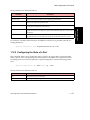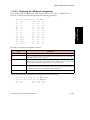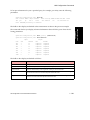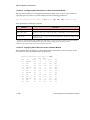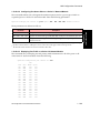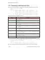
1
fs
AMI Configuration Commands
Reference Manual
MANU0265-02 - Rev. A - 12/19/97
Software Version 5.1.x
FORE Systems, Inc.
1000 FORE Drive
Warrendale, PA 15086-7502
Phone: 412-742-4444
FAX: 412-742-7742
http://www.fore.com
Legal Notices
Copyright © 1995-1997 FORE Systems, Inc. All rights reserved. FORE Systems is a registered trademark, and ForeRunner,
ForeRunnerLE, ForeThought, ForeView, PowerHub, and CellPath are trademarks of FORE Systems, Inc. All other brands or
product names are trademarks or registered trademarks of their respective holders.
U.S. Government Restricted Rights. If you are licensing the Software on behalf of the U.S. Government (“Government”),
the following provisions apply to you. If the Software is supplied to the Department of Defense (“DoD”), it is classified as
“Commercial Computer Software” under paragraph 252.227-7014 of the DoD Supplement to the Federal Acquisition Regulations (“DFARS”) (or any successor regulations) and the Government is acquiring only the license rights granted herein
(the license rights customarily provided to non-Government users). If the Software is supplied to any unit or agency of the
Government other than DoD, it is classified as “Restricted Computer Software” and the Government’s rights in the Software are defined in paragraph 52.227-19 of the Federal Acquisition Regulations (“FAR”) (or any successor regulations) or,
in the cases of NASA, in paragraph 18.52.227-86 of the NASA Supplement to the FAR (or any successor regulations).
Printed in the USA.
No part of this work covered by copyright may be reproduced in any form. Reproduction, adaptation, or translation without prior written permission is prohibited, except as allowed under the copyright laws.
This publication is provided by FORE Systems, Inc. “as-is” without warranty of any kind, either express or implied, including, but not limited to, the implied warranties or conditions of merchantability or fitness for a particular purpose. FORE
Systems, Inc. shall not be liable for any errors or omissions which may occur in this publication, nor for incidental or consequential damages of any kind resulting from the furnishing, performance, or use of this publication.
Information published here is current or planned as of the date of publication of this document. Because we are improving
and adding features to our products continuously, the information in this document is subject to change without notice.
RESTRICTED RIGHTS LEGEND. Use, duplication, or disclosure by the government is subject to restrictions as set forth in
subparagraph (c)(1)(ii) of the Rights in Technical Data and Computer Software clause at DFARS 252.227-7013 (October
1988) and FAR 52.227-19 (June 1987).
The VxWorks software used in the Mini Loader is licensed from Wind River Systems, Inc., Copyright ©1984-1996.
FCC CLASS A NOTICE
WARNING: Changes or modifications to this unit not expressly approved by the party responsible for compliance could
void this user’s authority to operate this equipment.
NOTE: The ASX-200WG, the ASX-200BX, the ASX-1000, and the ForeRunnerLE 155 have been tested and found to comply
with the limits for a Class A digital device, pursuant to Part 15 of the FCC Rules. These limits are designed to provide reasonable protection against harmful interference when the equipment is operated in a commercial environment. This equipment generates, uses, and can radiate radio frequency energy and, if not installed and used in accordance with the
instruction manual, may cause harmful interference to radio communications. Operation of the equipment in a residential
area is likely to cause harmful interference in which case the user will be required to correct the interference at his own
expense.
DOC CLASS A NOTICE
This digital apparatus does not exceed Class A limits for radio noise emission for a digital device as set out in the Radio
Interference Regulations of the Canadian Department of Communications.
Le present appareil numerique n’emet pas de bruits radioelectriques depassant les limites applicables aux appareils numeriques de la class A prescrites dans le reglement sur le brouillage radioelectrique edicte par le ministere des Communications du Canada.
VCCI CLASS 1 NOTICE
This equipment is in the Class 1 category (Information Technology Equipment to be used in commercial and/or industrial
areas) and conforms to the standards set by the Voluntary Control Council For Interference by Information Technology
Equipment aimed at preventing radio interference in commercial and/or industrial areas.Consequently, when used in a
residential area or in an adjacent area thereto, radio interference may be caused to radios and TV receivers, etc. Read the
instructions for correct handling.
FCC REQUIREMENTS (Notice to Users of DS1 Service)
The following instructions are provided to ensure compliance with the Federal Communications Commission (FCC) Rules,
Part 68.
(1)
This device must only be connected to the DS1 network connected behind an FCC Part 68
registered channel service unit. Direct connection is not allowed.
(2)
Before connecting your unit, you must inform the telephone company of the following
information:
Port ID
REN/SOC
FIC
USOC
NM-6/DS1C
6.0N
RJ48C
NM-2/DS1C
6.0N
04DU9-BN,
04DU9-DN,
04DU9-1ZN, and
04DU9-1SN
RJ48C
(3)
If the unit appears to be malfunctioning, it should be disconnected from the telephone lines
until you learn if your equipment or the telephone line is the source of the trouble. If your
equipment needs repair, it should not be reconnected until it is repaired.
(4)
If the telephone company finds that this equipment is exceeding tolerable parameters, the
telephone company can temporarily disconnect service, although they will attempt to give
you advance notice if possible.
(5)
Under the FCC Rules, no customer is authorized to repair this equipment. This restriction
applies regardless of whether the equipment is in or out of warranty.
(6)
If the telephone company alters their equipment in a manner that will affect use of this
device, they must give you advance warning so as to give you the opportunity for uninterrupted service. You will be advised of your right to file a complaint with the FCC.
CANADIAN IC CS-03 COMPLIANCE STATEMENT
NOTICE: The Industry Canada label identifies certified equipment. This certification means that the equipment meets certain telecommunications network protective, operational and safety requirements. The Industry Canada label does not
guarantee the equipment will operate to the user’s satisfaction.
Before installing this equipment, users should ensure that it is permissible to be connected to the facilities of the local telecommunications company. The equipment must also be installed using an acceptable method of connection. In some cases,
the company’s inside wiring associated with a single line individual service may be extended by means of a certified connector assembly (telephone extension cord). The customer should be aware that compliance with the above conditions may
not prevent degradation of service in some situations.
Repairs to certified equipment should be made by an authorized Canadian maintenance facility designated by the supplier.
Any repairs or alterations made by the user to this equipment, or equipment malfunctions, may give the telecommunications company cause to request the user to disconnect the equipment.
Users should ensure for their own protection that the electrical ground connections of the power utility, telephone lines and
internal metallic water pipe system, if present, are connected together. This precaution may be particularly important in
rural areas.
Caution: Users should not attempt to make such connections themselves, but should contact the appropriate electric
inspection authority, or electrician, as appropriate.
E1 AND E3 NOTICE
The E1 (NM-6/E1C and NM-2/E1C) and E3 (NM-4/E3C and NM-2/E3C) network modules that are described in this
manual are approved for use in FORE Systems’ host systems providing that the instructions below are strictly observed.
Failure to follow these instructions invalidates the approval.
Pan European Approval - CE Marking
Pan European approval of the E1 network module was issued by BABT following assessment against CTR12. This means
that it can be connected to ONP and unstructured PTO-provided private circuits with 120 Ω interfaces in all European
countries, according to Telecommunications Terminal Equipment (TTE) Directive 91/263/EEC. Thus, the following CE
mark applies:
168 X
The E1 and E3 network modules conform to safety standard EN60950 1992 following the provisions of Low Voltage
Product Safety Directive 73/23/EEC and CE Marking Directive 93/68/EEC, and can be marked accordingly with the CE
symbol.
The E1 and E3 network modules conform to EN55022 1994 and EN50082-1 1992 following the provisions of the EMC
Directive 89/336/EEC, and can be marked accordingly with the CE symbol.
National Approvals
UK
Network Module
Connects to
Approval Number
E1
Structured and unstructured
PTO-provided private circuits
with 75 Ω interfaces
PTO-provided private circuits
with 75 Ω interfaces
AA60953
E3
NS/4387/1/T/605954
Germany
Network Module
Connects to
Approval Number
E3
Structured PTO-provided private circuits
with 75 Ω interfaces
A127535H for the ASX-1000
A127534H for the ASX-200BX or ASX-200WG
Network Module
Connects to
Approval Number
E1
Structured PTO-provided private circuits
with 120 Ω interfaces
Structured PTO-provided private circuits
with 75 Ω interfaces
96.0872.J.N
Switzerland
E3
96.0873.J.N
Required User Guide Statements - UK Installation
The use of auxiliary products not authorized by FORE Systems in FORE Systems ATM Switches may cause the power specification to be exceeded and is a potential safety hazard.
The equipment must be installed such that with the exception of the connections to the host, clearance and creepage
distances shown in the table below are maintained between the network module and any other assemblies which use or
generate a voltage shown in the table below. The larger distance shown in brackets applies where the local environment
within the host is subject to conductive pollution or dry non-conductive pollution which could become conductive due to
condensation. Failure to maintain these minimum distances invalidates the approval.
Clearance (mm)
Creepage (mm)
Voltage Used or Generated
by Host or by Network Modules
2.0
2.6
4.0
4.6
2.4 (3.8)
3.0 (4.8)
5.0 (8.0)
6.4 (10.0)
Up to 50 Vrms or Vdc
Up to 125 Vrms or Vdc
Up to 250 Vrms or Vdc
Up to 300 Vrms or Vdc
For a host or other expansion card fitted in the host, using or generating voltages greater
than 300V (rms or dc), advice from a competent telecommunications engineer must be
obtained before installation of the relevant equipment.
Above 300 Vrms or Vdc
NOTE: Installing the network modules in the appropriate FORE Systems hosts, according to the installation instructions
provided, satisfies the requirements listed above.
The following tables show the available ports and their safety status:
NM-6/E1C and NM-2/E1C
Ports
Safety Status
E1 Ports
Bus Connector
TNV operating at SELV
SELV
NM-4/E3C and NM-2/E3C
Ports
Safety Status
E3 Ports
Bus Connector
TNV operating at SELV
SELV
CE NOTICE
Marking by the symbol CE indicates compliance of this system to the EMC (Electromagnetic Compatibility) directive of the
European Community and compliance to the Low Voltage (Safety) Directive. Such marking is indicative that this system
meets or exceeds the following technical standards:
• EN 55022 - “Limits and Methods of Measurement of Radio Interference Characteristics of Information Technology Equipment.”
• EN 50082-1 - “Electromagnetic compatibility - Generic immunity standard Part 1: Residential, commercial,
and light industry.”
• IEC 1000-4-2 - “Electromagnetic compatibility for industrial-process measurement and control equipment
Part 2: Electrostatic discharge requirements.”
• IEC 1000-4-3 - “Electromagnetic compatibility for industrial-process measurement and control equipment
Part 3: Radiate electromagnetic field requirements.”
• IEC 1000-4-4 - “Electromagnetic compatibility for industrial-process measurement and control equipment
Part 4: Electrical fast transient/burst requirements.”
SAFETY CERTIFICATIONS
ETL certified to meet Information Technology Equipment safety standards UL 1950, CSA 22.2 No. 950, and EN 60950.
Table of Contents
Preface
Chapter Summaries. . . . . . . . . . . . . . . . . . . . . . . . . . . . . . . . . . . . . . . . . . . . . . . . . . . . . . . . . . i
Related Manuals . . . . . . . . . . . . . . . . . . . . . . . . . . . . . . . . . . . . . . . . . . . . . . . . . . . . . . . . . . . . i
Technical Support . . . . . . . . . . . . . . . . . . . . . . . . . . . . . . . . . . . . . . . . . . . . . . . . . . . . . . . . . . .ii
Typographical Styles . . . . . . . . . . . . . . . . . . . . . . . . . . . . . . . . . . . . . . . . . . . . . . . . . . . . . . . . iii
Important Information Indicators . . . . . . . . . . . . . . . . . . . . . . . . . . . . . . . . . . . . . . . . . . . . . . . iv
Invisible Laser Radiation Notice . . . . . . . . . . . . . . . . . . . . . . . . . . . . . . . . . . . . . . . . . . . . . . . .v
Safety Precautions. . . . . . . . . . . . . . . . . . . . . . . . . . . . . . . . . . . . . . . . . . . . . . . . . . . . . . . . . . vi
Modifications to Equipment . . . . . . . . . . . . . . . . . . . . . . . . . . . . . . . . . . . . . . . . . . . . vi
CHAPTER 1
1.1
1.2
1.3
AMI Configuration Commands
Alarms Configuration Commands. . . . . . . . . . . . . . . . . . . . . . . . . . . . . . . . . . . . . . 1 - 1
1.1.1
Displaying Alarm Conditions . . . . . . . . . . . . . . . . . . . . . . . . . . . . . . . . . 1 - 2
1.1.2
Enabling an Alarm . . . . . . . . . . . . . . . . . . . . . . . . . . . . . . . . . . . . . . . . . 1 - 3
1.1.3
Disabling an Alarm . . . . . . . . . . . . . . . . . . . . . . . . . . . . . . . . . . . . . . . . . 1 - 4
1.1.4
Resetting an Alarm. . . . . . . . . . . . . . . . . . . . . . . . . . . . . . . . . . . . . . . . . 1 - 5
1.1.5
Network Module Alarm Commands . . . . . . . . . . . . . . . . . . . . . . . . . . . . 1 - 6
1.1.5.1 Displaying the Network Module Alarm Configuration . . . . . . . . 1 - 6
1.1.5.2 Configuring Network Module Alarm Priorities . . . . . . . . . . . . . . 1 - 7
ATM ARP Configuration Commands . . . . . . . . . . . . . . . . . . . . . . . . . . . . . . . . . . . 1 - 9
1.2.1
ARP Server Configuration Commands. . . . . . . . . . . . . . . . . . . . . . . . . . 1 - 9
1.2.1.1 Displaying the ARP Server Address . . . . . . . . . . . . . . . . . . . . . 1 - 9
1.2.1.2 Setting the ARP Server Address . . . . . . . . . . . . . . . . . . . . . . . 1 - 10
1.2.2
Deleting an ARP Entry . . . . . . . . . . . . . . . . . . . . . . . . . . . . . . . . . . . . . 1 - 10
1.2.3
Flushing the ATM ARP Cache . . . . . . . . . . . . . . . . . . . . . . . . . . . . . . . 1 - 11
1.2.4
Getting the NSAP Address for a Classical IP Interface . . . . . . . . . . . . 1 - 11
1.2.5
Creating an IP to NSAP Address Mapping. . . . . . . . . . . . . . . . . . . . . . 1 - 11
1.2.6
Creating a Classical IP PVC. . . . . . . . . . . . . . . . . . . . . . . . . . . . . . . . . 1 - 12
1.2.7
Creating a FORE IP PVC ARP Entry . . . . . . . . . . . . . . . . . . . . . . . . . 1 - 12
1.2.8
Displaying the ATM ARP Entries . . . . . . . . . . . . . . . . . . . . . . . . . . . . . 1 - 13
ATM Route Configuration Commands . . . . . . . . . . . . . . . . . . . . . . . . . . . . . . . . . 1 - 14
1.3.1
Displaying ATM Routing Information . . . . . . . . . . . . . . . . . . . . . . . . . . 1 - 14
1.3.2
Configuring a Domain. . . . . . . . . . . . . . . . . . . . . . . . . . . . . . . . . . . . . . 1 - 18
1.3.2.1 Deleting a Domain . . . . . . . . . . . . . . . . . . . . . . . . . . . . . . . . . . 1 - 18
1.3.2.2 Modifying a Domain. . . . . . . . . . . . . . . . . . . . . . . . . . . . . . . . . 1 - 18
1.3.2.3 Creating a Domain . . . . . . . . . . . . . . . . . . . . . . . . . . . . . . . . . 1 - 18
AMI Configuration Commands Reference Manual
TOC - 1
Table of Contents
1.3.3
1.3.4
TOC - 2
1.3.2.4 Displaying Domain Information. . . . . . . . . . . . . . . . . . . . . . . .
ForeThought PNNI Configuration Commands. . . . . . . . . . . . . . . . . . .
1.3.3.1 Changing the ForeThought PNNI Border Switch
Functionality . . . . . . . . . . . . . . . . . . . . . . . . . . . . . . . . . . . . . .
1.3.3.2 DTL Configuration Commands . . . . . . . . . . . . . . . . . . . . . . . .
1.3.3.2.1
Deleting a DTL Entry . . . . . . . . . . . . . . . . . . . . . . .
1.3.3.2.2
Modifying a DTL Entry . . . . . . . . . . . . . . . . . . . . . .
1.3.3.2.3
Creating a DTL Entry. . . . . . . . . . . . . . . . . . . . . . .
1.3.3.2.4
Displaying DTLs. . . . . . . . . . . . . . . . . . . . . . . . . . .
1.3.3.3 Configuring the FORE Area . . . . . . . . . . . . . . . . . . . . . . . . . .
1.3.3.4 Configuring the FORE Level. . . . . . . . . . . . . . . . . . . . . . . . . .
1.3.3.5 Setting the Hello Indication Interval . . . . . . . . . . . . . . . . . . . .
1.3.3.6 Setting the Maximum Hop Count . . . . . . . . . . . . . . . . . . . . . .
1.3.3.7 ForeThought PNNI Metric Configuration Commands . . . . . . .
1.3.3.7.1
Deleting a Metric Set . . . . . . . . . . . . . . . . . . . . . . .
1.3.3.7.2
Modifying a Metric Set . . . . . . . . . . . . . . . . . . . . . .
1.3.3.7.3
Creating a Metric Set. . . . . . . . . . . . . . . . . . . . . . .
1.3.3.7.4
Displaying Metric Set Information . . . . . . . . . . . . .
1.3.3.8 Setting a Minimum Threshold for NSAP Updates . . . . . . . . .
1.3.3.9 Setting the NSAP Indication Interval . . . . . . . . . . . . . . . . . . .
1.3.3.10 Setting the ForeThought PNNI Peer Group Mask . . . . . . . . .
1.3.3.11 Selecting the Method for Computing the Cost of a Link . . . . .
1.3.3.12 Setting the ForeThought PNNI Switch Prefix . . . . . . . . . . . . .
1.3.3.13 Setting the Proportional Multiplier . . . . . . . . . . . . . . . . . . . . .
1.3.3.14 Static Route Configuration Commands . . . . . . . . . . . . . . . . .
1.3.3.14.1 Deleting a Static Route . . . . . . . . . . . . . . . . . . . . .
1.3.3.14.2 Creating a Static Route . . . . . . . . . . . . . . . . . . . . .
1.3.3.14.3 Displaying Static Routes . . . . . . . . . . . . . . . . . . . .
1.3.3.15 Setting the ForeThought PNNI Switch Prefix Mask . . . . . . . .
1.3.3.16 Setting a Minimum Virtual Channel Mark . . . . . . . . . . . . . . . .
1.3.3.17 Displaying ForeThought PNNI Parameters. . . . . . . . . . . . . . .
ATM Forum PNNI Configuration Commands. . . . . . . . . . . . . . . . . . . .
1.3.4.1 PNNI Address Configuration Commands . . . . . . . . . . . . . . . .
1.3.4.1.1
Deleting a PNNI Exterior Reachability
Address . . . . . . . . . . . . . . . . . . . . . . . . . . . . . . . . .
1.3.4.1.2
Modifying a PNNI Exterior Reachability
Address . . . . . . . . . . . . . . . . . . . . . . . . . . . . . . . . .
1.3.4.1.3
Creating a PNNI Exterior Reachability
Address . . . . . . . . . . . . . . . . . . . . . . . . . . . . . . . . .
1.3.4.1.4
Displaying PNNI Exterior Reachability
Address Information. . . . . . . . . . . . . . . . . . . . . . . .
1.3.4.2 PNNI Crankback Configuration Commands . . . . . . . . . . . . . .
1.3.4.2.1
Displaying the Crankback Setting . . . . . . . . . . . . .
1 - 19
1 - 20
1 - 20
1 - 21
1 - 21
1 - 21
1 - 22
1 - 23
1 - 24
1 - 24
1 - 25
1 - 25
1 - 26
1 - 26
1 - 26
1 - 26
1 - 27
1 - 28
1 - 28
1 - 29
1 - 29
1 - 30
1 - 30
1 - 31
1 - 31
1 - 31
1 - 33
1 - 34
1 - 34
1 - 35
1 - 37
1 - 37
1 - 37
1 - 37
1 - 37
1 - 39
1 - 41
1 - 41
AMI Configuration Commands Reference Manual
1.3.4.2.2
Configuring the Crankback Setting . . . . . . . . . . . . . 1 - 41
PNNI Interface Configuration Commands . . . . . . . . . . . . . . . . 1 - 42
1.3.4.3.1
Modifying a PNNI Interface. . . . . . . . . . . . . . . . . . . 1 - 42
1.3.4.3.2
Displaying a PNNI Interface . . . . . . . . . . . . . . . . . . 1 - 43
1.3.4.4 PNNI Metric Configuration Commands . . . . . . . . . . . . . . . . . . 1 - 44
1.3.4.4.1
Deleting a Metric Set . . . . . . . . . . . . . . . . . . . . . . . 1 - 44
1.3.4.4.2
Modifying a Metric Set . . . . . . . . . . . . . . . . . . . . . . 1 - 44
1.3.4.4.3
Creating a Metric Set . . . . . . . . . . . . . . . . . . . . . . . 1 - 44
1.3.4.4.4
Displaying Metric Set Information . . . . . . . . . . . . . . 1 - 46
1.3.4.5 PNNI Node Configuration Commands. . . . . . . . . . . . . . . . . . . 1 - 48
1.3.4.5.1
Configuring the PNNI Node State. . . . . . . . . . . . . . 1 - 48
1.3.4.5.2
Deleting a PNNI Node . . . . . . . . . . . . . . . . . . . . . . 1 - 48
1.3.4.5.3
Creating a PNNI Node . . . . . . . . . . . . . . . . . . . . . . 1 - 49
1.3.4.5.4
Modifying a PNNI Node . . . . . . . . . . . . . . . . . . . . . 1 - 50
1.3.4.5.5
Displaying PNNI Node Information . . . . . . . . . . . . . 1 - 52
1.3.4.6 PNNI Profile Configuration Commands . . . . . . . . . . . . . . . . . . 1 - 56
1.3.4.6.1
Deleting a PNNI Profile. . . . . . . . . . . . . . . . . . . . . . 1 - 56
1.3.4.6.2
Modifying a PNNI Profile . . . . . . . . . . . . . . . . . . . . 1 - 56
1.3.4.6.3
Creating a PNNI Profile . . . . . . . . . . . . . . . . . . . . . 1 - 56
1.3.4.6.4
Displaying PNNI Profile Information . . . . . . . . . . . . 1 - 58
1.3.5
PNNI Policy Prefix Configuration Commands . . . . . . . . . . . . . . . . . . . 1 - 61
1.3.5.1 Deleting a PNNI Policy Prefix . . . . . . . . . . . . . . . . . . . . . . . . . 1 - 61
1.3.5.2 Modifying a PNNI Policy Prefix . . . . . . . . . . . . . . . . . . . . . . . . 1 - 61
1.3.5.3 Creating a PNNI Policy Prefix . . . . . . . . . . . . . . . . . . . . . . . . . 1 - 61
1.3.5.4 Displaying PNNI Policy Prefix Information. . . . . . . . . . . . . . . . 1 - 63
1.3.6
SPANS ATM Route Configuration Commands . . . . . . . . . . . . . . . . . . . 1 - 64
1.3.6.1 Setting the SPANS Area ID . . . . . . . . . . . . . . . . . . . . . . . . . . . 1 - 64
1.3.6.2 Setting the SPANS-NNI Border Switch Functionality. . . . . . . . 1 - 65
1.3.6.3 Displaying SPANS-NNI Parameters . . . . . . . . . . . . . . . . . . . . 1 - 65
Switch Board Configuration Commands. . . . . . . . . . . . . . . . . . . . . . . . . . . . . . . . 1 - 66
1.4.1
Configuring the Clock Scaling Factor on a Switch Board . . . . . . . . . . . 1 - 66
1.4.2
Configuring OAM Cell Processing on a Switch Board . . . . . . . . . . . . . 1 - 67
1.4.3
Displaying the Board Configuration . . . . . . . . . . . . . . . . . . . . . . . . . . . 1 - 68
CEC Configuration . . . . . . . . . . . . . . . . . . . . . . . . . . . . . . . . . . . . . . . . . . . . . . . . 1 - 69
1.5.1
Alarms Configuration Commands . . . . . . . . . . . . . . . . . . . . . . . . . . . . 1 - 69
1.5.1.1 Disabling an Alarm . . . . . . . . . . . . . . . . . . . . . . . . . . . . . . . . . 1 - 69
1.5.1.2 Enabling an Alarm . . . . . . . . . . . . . . . . . . . . . . . . . . . . . . . . . . 1 - 70
1.5.1.3 Configuring an Alarm Relay . . . . . . . . . . . . . . . . . . . . . . . . . . 1 - 71
1.5.1.3.1
Setting an Alarm Relay . . . . . . . . . . . . . . . . . . . . . . 1 - 71
1.5.1.3.2
Displaying the Alarm Relays. . . . . . . . . . . . . . . . . . 1 - 71
1.5.1.4 Displaying Alarm Conditions . . . . . . . . . . . . . . . . . . . . . . . . . . 1 - 72
1.5.2
TCM Selection . . . . . . . . . . . . . . . . . . . . . . . . . . . . . . . . . . . . . . . . . . . 1 - 73
1.5.3
TCM Configuration Commands . . . . . . . . . . . . . . . . . . . . . . . . . . . . . . 1 - 73
1.3.4.3
1.4
1.5
AMI Configuration Commands Reference Manual
TOC - 3
Table of Contents
1.5.3.1
1.6
1.7
TOC - 4
IP Configuration Commands . . . . . . . . . . . . . . . . . . . . . . . . .
1.5.3.1.1
Configuring the IP Address . . . . . . . . . . . . . . . . . .
1.5.3.1.2
Configuring the IP State . . . . . . . . . . . . . . . . . . . .
1.5.3.1.3
Configuring the IP Broadcast Address . . . . . . . . .
1.5.3.1.4
Configuring the IP Subnet Mask . . . . . . . . . . . . . .
1.5.3.1.5
Configuring IP Routes . . . . . . . . . . . . . . . . . . . . . .
1.5.3.1.5.1
Adding an IP Route. . . . . . . . . . . . . . . .
1.5.3.1.5.2
Deleting an IP Route. . . . . . . . . . . . . . .
1.5.3.1.5.3
Showing the IP Routes . . . . . . . . . . . . .
1.5.3.1.6
Displaying the IP Interface Configuration. . . . . . . .
1.5.3.2 Setting or Changing the TCM’s Name . . . . . . . . . . . . . . . . . .
1.5.3.3 Serial Port Configuration . . . . . . . . . . . . . . . . . . . . . . . . . . . .
1.5.3.3.1
Displaying Serial Port Information . . . . . . . . . . . . .
1.5.3.4 Displaying TCM Information . . . . . . . . . . . . . . . . . . . . . . . . . .
1.5.3.5 SNMP Configuration Commands . . . . . . . . . . . . . . . . . . . . . .
1.5.3.5.1
Configuring SNMP Traps . . . . . . . . . . . . . . . . . . . .
1.5.3.5.1.1
Deleting an SNMP Trap Entry. . . . . . . .
1.5.3.5.1.2
Creating an SNMP Trap Entry . . . . . . .
1.5.3.5.1.3
Displaying the SNMP Trap
Entries. . . . . . . . . . . . . . . . . . . . . . . . . .
1.5.3.6 Setting or Changing the Timezone . . . . . . . . . . . . . . . . . . . . .
1.5.4
CEC Timing Configuration. . . . . . . . . . . . . . . . . . . . . . . . . . . . . . . . . .
1.5.4.1 BITS Timing Configuration Commands . . . . . . . . . . . . . . . . .
1.5.4.1.1
BITS Coding Configuration . . . . . . . . . . . . . . . . . .
1.5.4.1.2
BITS Framing Configuration . . . . . . . . . . . . . . . . .
1.5.4.1.3
BITS Level Configuration . . . . . . . . . . . . . . . . . . . .
1.5.4.2 Failover Timing Configuration . . . . . . . . . . . . . . . . . . . . . . . . .
1.5.4.2.1
Configuring the Failover Timing Delay . . . . . . . . . .
1.5.4.3 Timing Mode Configuration . . . . . . . . . . . . . . . . . . . . . . . . . .
1.5.4.4 Primary Timing Configuration. . . . . . . . . . . . . . . . . . . . . . . . .
1.5.4.5 Displaying Timing References . . . . . . . . . . . . . . . . . . . . . . . .
1.5.4.6 Revertive Timing Configuration . . . . . . . . . . . . . . . . . . . . . . .
1.5.4.6.1
Configuring the Revertive Timing Delay . . . . . . . .
1.5.4.6.2
Disabling Revertive Timing Delay . . . . . . . . . . . . .
1.5.4.6.3
Enabling the Revertive Timing Delay. . . . . . . . . . .
1.5.4.7 Secondary Timing Configuration . . . . . . . . . . . . . . . . . . . . . .
1.5.4.8 Displaying Timing . . . . . . . . . . . . . . . . . . . . . . . . . . . . . . . . . .
CES Configuration Command . . . . . . . . . . . . . . . . . . . . . . . . . . . . . . . . . . . . . . .
1.6.1
Creating a New CES Connection . . . . . . . . . . . . . . . . . . . . . . . . . . . .
1.6.2
Deleting a CES Connection. . . . . . . . . . . . . . . . . . . . . . . . . . . . . . . . .
1.6.3
Displaying CES Connections. . . . . . . . . . . . . . . . . . . . . . . . . . . . . . . .
ILMI SNMP Proxy Configuration Commands . . . . . . . . . . . . . . . . . . . . . . . . . . .
1.7.1
Deleting an ISP Table Entry . . . . . . . . . . . . . . . . . . . . . . . . . . . . . . . .
1 - 73
1 - 74
1 - 74
1 - 74
1 - 75
1 - 75
1 - 75
1 - 76
1 - 76
1 - 77
1 - 77
1 - 78
1 - 78
1 - 79
1 - 80
1 - 80
1 - 80
1 - 81
1 - 81
1 - 82
1 - 83
1 - 83
1 - 83
1 - 84
1 - 84
1 - 85
1 - 85
1 - 86
1 - 87
1 - 88
1 - 89
1 - 89
1 - 90
1 - 90
1 - 91
1 - 92
1 - 94
1 - 94
1 - 96
1 - 97
1 - 99
1 - 99
AMI Configuration Commands Reference Manual
1.8
1.9
1.7.2
Resending an ILMI SNMP Proxy Request . . . . . . . . . . . . . . . . . . . . . . 1 - 99
1.7.3
Creating an ISP Table Entry . . . . . . . . . . . . . . . . . . . . . . . . . . . . . . . . 1 - 100
1.7.4
Displaying the ISP Table Entries . . . . . . . . . . . . . . . . . . . . . . . . . . . . 1 - 101
IP Configuration Commands . . . . . . . . . . . . . . . . . . . . . . . . . . . . . . . . . . . . . . . 1 - 103
1.8.1
Configuring the IP Address . . . . . . . . . . . . . . . . . . . . . . . . . . . . . . . . 1 - 103
1.8.2
Configuring the IP State . . . . . . . . . . . . . . . . . . . . . . . . . . . . . . . . . . . 1 - 104
1.8.3
Configuring the IP Broadcast Address . . . . . . . . . . . . . . . . . . . . . . . . 1 - 104
1.8.4
Configuring IP Forwarding . . . . . . . . . . . . . . . . . . . . . . . . . . . . . . . . . 1 - 105
1.8.5
Configuring the IP Subnet Mask. . . . . . . . . . . . . . . . . . . . . . . . . . . . . 1 - 105
1.8.6
Configuring the MTU Size of a Classical IP Interface. . . . . . . . . . . . . 1 - 105
1.8.7
Configuring IP Routes . . . . . . . . . . . . . . . . . . . . . . . . . . . . . . . . . . . . 1 - 106
1.8.7.1 Adding an IP Route . . . . . . . . . . . . . . . . . . . . . . . . . . . . . . . . 1 - 106
1.8.7.2 Deleting an IP Route . . . . . . . . . . . . . . . . . . . . . . . . . . . . . . . 1 - 106
1.8.7.3 Showing the IP Routes . . . . . . . . . . . . . . . . . . . . . . . . . . . . . 1 - 107
1.8.8
Displaying the IP Interface Configuration . . . . . . . . . . . . . . . . . . . . . . 1 - 108
1.8.9
Unconfiguring an IP Interface . . . . . . . . . . . . . . . . . . . . . . . . . . . . . . . 1 - 109
LAN Emulation Configuration Commands . . . . . . . . . . . . . . . . . . . . . . . . . . . . . 1 - 110
1.9.1
Default LANE Configuration Commands . . . . . . . . . . . . . . . . . . . . . . 1 - 110
1.9.1.1 Creating a Default ELAN . . . . . . . . . . . . . . . . . . . . . . . . . . . . 1 - 110
1.9.1.2 Deleting a Default ELAN . . . . . . . . . . . . . . . . . . . . . . . . . . . . 1 - 111
1.9.1.3 Displaying a Default ELAN . . . . . . . . . . . . . . . . . . . . . . . . . . 1 - 112
1.9.2
BUS Configuration Commands . . . . . . . . . . . . . . . . . . . . . . . . . . . . . 1 - 114
1.9.2.1 Configuring the BUS Administrative Status . . . . . . . . . . . . . . 1 - 114
1.9.2.2 Deleting a BUS . . . . . . . . . . . . . . . . . . . . . . . . . . . . . . . . . . . 1 - 114
1.9.2.3 Creating a BUS . . . . . . . . . . . . . . . . . . . . . . . . . . . . . . . . . . . 1 - 115
1.9.2.4 Displaying BUS Information. . . . . . . . . . . . . . . . . . . . . . . . . . 1 - 116
1.9.3
LAN Emulation Client (LEC) Configuration Commands . . . . . . . . . . . 1 - 117
1.9.3.1 Configuring the LEC Administrative Status . . . . . . . . . . . . . . 1 - 117
1.9.3.2 Configuring LANE ARP Commands . . . . . . . . . . . . . . . . . . . 1 - 117
1.9.3.2.1
Deleting LANE ARP Cache Information . . . . . . . . 1 - 118
1.9.3.2.2
Displaying LANE ARP Cache Information . . . . . . 1 - 118
1.9.3.3 Deleting a LEC . . . . . . . . . . . . . . . . . . . . . . . . . . . . . . . . . . . 1 - 119
1.9.3.4 LEC Default Configuration Mode Commands . . . . . . . . . . . . 1 - 119
1.9.3.4.1
Setting the Default LEC Configuration Mode . . . . 1 - 120
1.9.3.4.2
Displaying the Default LEC Configuration
Mode. . . . . . . . . . . . . . . . . . . . . . . . . . . . . . . . . . . 1 - 120
1.9.3.5 Creating an Ethernet LEC . . . . . . . . . . . . . . . . . . . . . . . . . . . 1 - 121
1.9.3.6 Displaying LEC Information . . . . . . . . . . . . . . . . . . . . . . . . . . 1 - 123
1.9.4
LAN Emulation Configuration Server (LECS) Commands . . . . . . . . . 1 - 126
1.9.4.1 Configuring the LECS Administrative Status . . . . . . . . . . . . . 1 - 126
1.9.4.2 Deleting a LECS . . . . . . . . . . . . . . . . . . . . . . . . . . . . . . . . . . 1 - 126
1.9.4.3 Creating a LECS . . . . . . . . . . . . . . . . . . . . . . . . . . . . . . . . . . 1 - 127
1.9.4.4 Displaying LECS Information. . . . . . . . . . . . . . . . . . . . . . . . . 1 - 128
AMI Configuration Commands Reference Manual
TOC - 5
Table of Contents
1.9.4.5 Getting the LECS Configuration File . . . . . . . . . . . . . . . . . .
LAN Emulation Server (LES) Configuration Commands . . . . . . . . . .
1.9.5.1 Configuring the LES Administrative Status. . . . . . . . . . . . . .
1.9.5.2 Deleting a LES . . . . . . . . . . . . . . . . . . . . . . . . . . . . . . . . . . .
1.9.5.3 Creating a LES . . . . . . . . . . . . . . . . . . . . . . . . . . . . . . . . . . .
1.9.5.4 Adding a DLE Peer . . . . . . . . . . . . . . . . . . . . . . . . . . . . . . . .
1.9.5.5 Deleting a DLE Peer . . . . . . . . . . . . . . . . . . . . . . . . . . . . . . .
1.9.5.6 Enabling/Disabling ELAN Access Control . . . . . . . . . . . . . .
1.9.5.7 Displaying LES Information . . . . . . . . . . . . . . . . . . . . . . . . .
Network Module Configuration Commands . . . . . . . . . . . . . . . . . . . . . . . . . . . .
1.10.1
Configuring the State of a Network Module. . . . . . . . . . . . . . . . . . . .
1.10.2
Resetting a Network Module . . . . . . . . . . . . . . . . . . . . . . . . . . . . . . .
1.10.3
Displaying Network Module Configuration Information . . . . . . . . . . .
1.10.4
Configuring Traffic on a Network Module. . . . . . . . . . . . . . . . . . . . . .
1.10.4.1 Configuring Traffic on a Series C Network Module. . . . . . . .
1.10.4.1.1 Setting Early Packet Discard on a
Series C Network Module . . . . . . . . . . . . . . . . . .
1.10.4.2 Setting FIFO Blocking on a Series C Network Module. . . . .
1.10.4.3 Displaying Traffic Models for a Series C Network Module . .
1.10.4.4 Setting Traffic Models on a Series C Network Module . . . . .
1.10.4.5 Displaying Traffic on a Series C Network Module. . . . . . . . .
1.10.4.6 Configuring Traffic on a Series LC Network Module. . . . . . .
1.10.4.6.1 Setting EPD on a Series LC Network Module . . .
1.10.4.6.2 Setting EFCI on a Series LC Network Module . .
1.10.4.6.3 Displaying Traffic Models for a Series LC
Network Module. . . . . . . . . . . . . . . . . . . . . . . . . .
1.10.4.6.4 Setting Traffic Models on a Series LC
Network Module. . . . . . . . . . . . . . . . . . . . . . . . . .
1.10.4.6.5 Displaying Traffic on a Series LC
Network Module. . . . . . . . . . . . . . . . . . . . . . . . . .
1.10.4.7 Configuring Traffic on a Series LE Network Module . . . . . . .
1.10.4.7.1 Setting EPD on a Series LE Network Module . . .
1.10.4.7.2 Setting EFCI on a Series LE Network Module. . .
1.10.4.7.3 Displaying Traffic Models for a Series LE
Network Module. . . . . . . . . . . . . . . . . . . . . . . . . .
1.10.4.7.4 Setting Traffic Models on a Series LE
Network Module. . . . . . . . . . . . . . . . . . . . . . . . . .
1.10.4.7.5 Displaying Traffic on a Series LE Network
Module . . . . . . . . . . . . . . . . . . . . . . . . . . . . . . . . .
1.10.4.8 Configuring Traffic on a Series D Network Module. . . . . . . .
1.10.4.8.1 Enabling/Disabling the AAL5 Transmitted
PDU Counter . . . . . . . . . . . . . . . . . . . . . . . . . . . .
1.10.4.8.2 Configuring Alternate CLP Thresholds . . . . . . . .
1.9.5
1.10
TOC - 6
1 - 130
1 - 131
1 - 131
1 - 131
1 - 132
1 - 134
1 - 135
1 - 136
1 - 137
1 - 141
1 - 141
1 - 142
1 - 143
1 - 144
1 - 144
1 - 144
1 - 145
1 - 145
1 - 146
1 - 147
1 - 148
1 - 148
1 - 149
1 - 150
1 - 151
1 - 152
1 - 153
1 - 153
1 - 154
1 - 155
1 - 156
1 - 157
1 - 158
1 - 158
1 - 159
AMI Configuration Commands Reference Manual
1.10.4.8.3
1.10.4.8.4
1.10.4.8.5
1.11
1.12
Setting EPD on a Series D Network Module . . . . 1 - 160
Setting EFCI on a Series D Network Module . . . . 1 - 161
Displaying Traffic Models for a Series D
Network Module . . . . . . . . . . . . . . . . . . . . . . . . . . 1 - 162
1.10.4.8.6 Setting Traffic Models on a Series D
Network Module . . . . . . . . . . . . . . . . . . . . . . . . . . 1 - 163
1.10.4.8.7 Displaying Traffic on a Series D Network
Module . . . . . . . . . . . . . . . . . . . . . . . . . . . . . . . . . 1 - 164
1.10.4.8.8 Configuring the VC CLP Threshold on a
Series D Network Module. . . . . . . . . . . . . . . . . . . 1 - 166
NSAP Configuration Commands . . . . . . . . . . . . . . . . . . . . . . . . . . . . . . . . . . . . 1 - 167
1.11.1
NSAP Prefix Configuration Commands . . . . . . . . . . . . . . . . . . . . . . . 1 - 167
1.11.1.1 Deleting an NSAP Prefix . . . . . . . . . . . . . . . . . . . . . . . . . . . . 1 - 167
1.11.1.2 Creating an NSAP Prefix . . . . . . . . . . . . . . . . . . . . . . . . . . . . 1 - 167
1.11.1.3 Displaying NSAP Prefixes . . . . . . . . . . . . . . . . . . . . . . . . . . . 1 - 168
1.11.2
NSAP ILMI Configuration Command . . . . . . . . . . . . . . . . . . . . . . . . . 1 - 169
1.11.2.1 Displaying NSAP Addresses Registered through ILMI . . . . . 1 - 169
1.11.3
NSAP-to-E.164 Configuration Commands . . . . . . . . . . . . . . . . . . . . . 1 - 170
1.11.3.1 Displaying NSAP-to-E.164 Address Mapping Information . . 1 - 170
1.11.3.2 Adding an NSAP-to-E.164 Address Mapping . . . . . . . . . . . . 1 - 171
1.11.3.3 Deleting an NSAP-to-E.164 Address Mapping . . . . . . . . . . . 1 - 171
1.11.4
ILMI LECS Address Registry Commands . . . . . . . . . . . . . . . . . . . . . 1 - 172
1.11.4.1 Displaying the ILMI LECS Address Registry . . . . . . . . . . . . . 1 - 172
1.11.4.2 Deleting an ILMI LECS Address Registry Entry . . . . . . . . . . 1 - 173
1.11.4.3 Adding an ILMI LECS Address Registry Entry . . . . . . . . . . . 1 - 174
Port Configuration Commands . . . . . . . . . . . . . . . . . . . . . . . . . . . . . . . . . . . . . . 1 - 176
1.12.1
AAL5 Packet Discard Command . . . . . . . . . . . . . . . . . . . . . . . . . . . . 1 - 176
1.12.2
Configuring the State of a Port . . . . . . . . . . . . . . . . . . . . . . . . . . . . . . 1 - 177
1.12.3
AISRDI Port Configuration Commands . . . . . . . . . . . . . . . . . . . . . . . 1 - 178
1.12.4
CAC Port Configuration Command . . . . . . . . . . . . . . . . . . . . . . . . . . 1 - 179
1.12.5
CDVT Port Configuration Command . . . . . . . . . . . . . . . . . . . . . . . . . 1 - 180
1.12.6
DS1 CES Port Configuration Commands. . . . . . . . . . . . . . . . . . . . . . 1 - 180
1.12.6.1 Enabling/Disabling CES on a Port . . . . . . . . . . . . . . . . . . . . . 1 - 180
1.12.6.2 Configuring DS1 CES Port Framing . . . . . . . . . . . . . . . . . . . 1 - 181
1.12.6.3 Configuring DS1 CES Port Line Length . . . . . . . . . . . . . . . . 1 - 181
1.12.6.4 Displaying DS1 CES Port Line Status . . . . . . . . . . . . . . . . . . 1 - 182
1.12.6.5 Configuring DS1 CES Port Loopback . . . . . . . . . . . . . . . . . . 1 - 183
1.12.6.6 Configuring the DS1 CES Port Line Coding . . . . . . . . . . . . . 1 - 183
1.12.6.7 Displaying the DS1 CES Port Configuration . . . . . . . . . . . . . 1 - 184
1.12.7
CESE1 Port Configuration Commands . . . . . . . . . . . . . . . . . . . . . . . 1 - 185
1.12.7.1 Enabling/Disabling CES on a Port . . . . . . . . . . . . . . . . . . . . . 1 - 185
1.12.7.2 Configuring CRC4 Framing on an E1 CES Port . . . . . . . . . . 1 - 186
1.12.7.3 Reserving TS16 for Signalling on an E1 CES Port . . . . . . . . 1 - 186
AMI Configuration Commands Reference Manual
TOC - 7
Table of Contents
1.12.7.4 Displaying E1 CES Port Line Status. . . . . . . . . . . . . . . . . . .
1.12.7.5 Configuring E1 CES Port Loopback . . . . . . . . . . . . . . . . . . .
1.12.7.6 Displaying the E1 CES Port Configuration . . . . . . . . . . . . . .
1.12.8
Configuring Port Delay . . . . . . . . . . . . . . . . . . . . . . . . . . . . . . . . . . .
1.12.9
DS1 Port Configuration Commands . . . . . . . . . . . . . . . . . . . . . . . . .
1.12.9.1 Configuring DS1 Port Empty Cells . . . . . . . . . . . . . . . . . . . .
1.12.9.2 Configuring DS1 Port Line Length . . . . . . . . . . . . . . . . . . . .
1.12.9.3 Configuring DS1 Port Loopback . . . . . . . . . . . . . . . . . . . . . .
1.12.9.4 Configuring DS1 Port Mode . . . . . . . . . . . . . . . . . . . . . . . . .
1.12.9.5 Configuring Pseudo-Random Bit Sequence Generation . . .
1.12.9.6 Configuring DS1 Port Scrambling. . . . . . . . . . . . . . . . . . . . .
1.12.9.7 Showing the DS1 Port Configuration . . . . . . . . . . . . . . . . . .
1.12.9.8 Configuring DS1 Port Timing . . . . . . . . . . . . . . . . . . . . . . . .
1.12.10 DS3 Port Configuration Commands . . . . . . . . . . . . . . . . . . . . . . . . .
1.12.10.1 Configuring DS3 Port Empty Cells. . . . . . . . . . . . . . . . . . . .
1.12.10.2 Configuring the DS3 Port Framing. . . . . . . . . . . . . . . . . . . .
1.12.10.3 Configuring DS3 Port Line Length . . . . . . . . . . . . . . . . . . . .
1.12.10.4 Configuring the DS3 Port Loopback . . . . . . . . . . . . . . . . . .
1.12.10.5 Configuring the DS3 Port Mode. . . . . . . . . . . . . . . . . . . . . .
1.12.10.6 Configuring the DS3 Port Scrambling . . . . . . . . . . . . . . . . .
1.12.10.7 Showing the DS3 Port Configuration . . . . . . . . . . . . . . . . . .
1.12.10.8 Configuring DS3 Port Timing . . . . . . . . . . . . . . . . . . . . . . . .
1.12.11 E1 Port Configuration Commands. . . . . . . . . . . . . . . . . . . . . . . . . . .
1.12.11.1 Configuring E1 Port Empty Cells . . . . . . . . . . . . . . . . . . . . .
1.12.11.2 Configuring E1 Port Line Length . . . . . . . . . . . . . . . . . . . . .
1.12.11.3 Configuring E1 Port Loopback. . . . . . . . . . . . . . . . . . . . . . .
1.12.11.4 Configuring E1 Port Mode . . . . . . . . . . . . . . . . . . . . . . . . . .
1.12.11.5 Configuring E1 Port Scrambling . . . . . . . . . . . . . . . . . . . . .
1.12.11.6 Showing the E1 Port Configuration . . . . . . . . . . . . . . . . . . .
1.12.11.7 Configuring E1 Port Timing . . . . . . . . . . . . . . . . . . . . . . . . .
1.12.12 E3 Port Configuration Commands. . . . . . . . . . . . . . . . . . . . . . . . . . .
1.12.12.1 Configuring E3 Port Empty Cells . . . . . . . . . . . . . . . . . . . . .
1.12.12.2 Configuring the E3 Port Loopback. . . . . . . . . . . . . . . . . . . .
1.12.12.3 Configuring E3 Port Mode . . . . . . . . . . . . . . . . . . . . . . . . . .
1.12.12.4 Configuring E3 Port Scrambling . . . . . . . . . . . . . . . . . . . . .
1.12.12.5 Showing the E3 Port Configuration . . . . . . . . . . . . . . . . . . .
1.12.12.6 Configuring E3 Port Timing . . . . . . . . . . . . . . . . . . . . . . . . .
1.12.13 GCRA Policing Command . . . . . . . . . . . . . . . . . . . . . . . . . . . . . . . . .
1.12.14 J2 Port Configuration Commands . . . . . . . . . . . . . . . . . . . . . . . . . . .
1.12.14.1 Configuring Empty Cells on a J2 Port . . . . . . . . . . . . . . . . .
1.12.14.2 Configuring J-2 Port Line Length . . . . . . . . . . . . . . . . . . . . .
1.12.14.3 Configuring J2 Port Loopback . . . . . . . . . . . . . . . . . . . . . . .
1.12.14.4 Showing J2 Port Configuration . . . . . . . . . . . . . . . . . . . . . .
TOC - 8
1 - 187
1 - 188
1 - 189
1 - 190
1 - 191
1 - 191
1 - 192
1 - 193
1 - 193
1 - 194
1 - 194
1 - 195
1 - 196
1 - 196
1 - 197
1 - 197
1 - 198
1 - 198
1 - 199
1 - 199
1 - 200
1 - 201
1 - 202
1 - 202
1 - 203
1 - 204
1 - 204
1 - 205
1 - 206
1 - 207
1 - 207
1 - 208
1 - 208
1 - 209
1 - 209
1 - 210
1 - 211
1 - 211
1 - 212
1 - 212
1 - 213
1 - 213
1 - 214
AMI Configuration Commands Reference Manual
1.12.14.5 Configuring J2 Port Timing . . . . . . . . . . . . . . . . . . . . . . . . . . 1 - 215
LED Port Configuration Commands . . . . . . . . . . . . . . . . . . . . . . . . . . 1 - 216
1.12.15.1 LED Model Configuration . . . . . . . . . . . . . . . . . . . . . . . . . . . 1 - 216
1.12.15.2 Displaying the LED Model Configuration . . . . . . . . . . . . . . . 1 - 217
1.12.16 Port Policing Configuration Command . . . . . . . . . . . . . . . . . . . . . . . . 1 - 218
1.12.17 Partial Packet Policing Command. . . . . . . . . . . . . . . . . . . . . . . . . . . . 1 - 219
1.12.18 Showing the Port Configuration . . . . . . . . . . . . . . . . . . . . . . . . . . . . . 1 - 220
1.12.19 SONET Port Configuration Commands . . . . . . . . . . . . . . . . . . . . . . . 1 - 224
1.12.19.1 Configuring SONET Port Empty Cells . . . . . . . . . . . . . . . . . 1 - 224
1.12.19.2 Configuring SONET Port Loopback . . . . . . . . . . . . . . . . . . . 1 - 225
1.12.19.3 Configuring SONET Port Mode . . . . . . . . . . . . . . . . . . . . . . 1 - 225
1.12.19.4 Configuring the SONET Port Scrambling . . . . . . . . . . . . . . . 1 - 226
1.12.19.5 Showing the SONET Port Configuration. . . . . . . . . . . . . . . . 1 - 226
1.12.19.6 Configuring SONET Port Timing . . . . . . . . . . . . . . . . . . . . . 1 - 229
1.12.20 TAXI Port Configuration Commands. . . . . . . . . . . . . . . . . . . . . . . . . . 1 - 230
1.12.20.1 Configuring TAXI Port Loopback. . . . . . . . . . . . . . . . . . . . . . 1 - 230
1.12.20.2 Showing the TAXI Port Configuration . . . . . . . . . . . . . . . . . . 1 - 231
1.12.21 TP25 Port Configuration Commands . . . . . . . . . . . . . . . . . . . . . . . . . 1 - 231
1.12.21.1 Configuring the TP25 Port Loopback . . . . . . . . . . . . . . . . . . 1 - 232
1.12.21.2 Showing the TP25 Port Configuration . . . . . . . . . . . . . . . . . 1 - 232
1.12.22 Port Traffic Configuration Commands. . . . . . . . . . . . . . . . . . . . . . . . . 1 - 234
1.12.22.1 Configuring Port Traffic on Series C Network Modules . . . . 1 - 234
1.12.22.1.1 Configuring Cell Delay Variation on a
Series C Network Module. . . . . . . . . . . . . . . . . . . 1 - 234
1.12.22.1.2 Setting the CLP Threshold on a Series C
Network Module . . . . . . . . . . . . . . . . . . . . . . . . . . 1 - 235
1.12.22.1.3 Configuring EFCI on a Series C Network
Module . . . . . . . . . . . . . . . . . . . . . . . . . . . . . . . . . 1 - 235
1.12.22.1.4 Configuring Port Queue Size on a Series C
Network Module . . . . . . . . . . . . . . . . . . . . . . . . . . 1 - 236
1.12.22.1.5 Displaying Port Traffic on a Series C
Network Module . . . . . . . . . . . . . . . . . . . . . . . . . . 1 - 236
1.12.22.2 Configuring Port Traffic on Series LC Network Modules . . . 1 - 238
1.12.22.2.1 Setting the CLP Threshold on a Series LC
Network Module . . . . . . . . . . . . . . . . . . . . . . . . . . 1 - 238
1.12.22.2.2 Configuring Port Queue Size on a Series
LC Network Module . . . . . . . . . . . . . . . . . . . . . . . 1 - 239
1.12.22.2.3 Displaying Port Traffic on a Series LC
Network Module . . . . . . . . . . . . . . . . . . . . . . . . . . 1 - 239
1.12.22.3 Configuring Port Traffic on Series LE Network Modules. . . . 1 - 241
1.12.22.3.1 Setting the CLP Threshold on a Series LE
Network Module . . . . . . . . . . . . . . . . . . . . . . . . . . 1 - 241
1.12.15
AMI Configuration Commands Reference Manual
TOC - 9
Table of Contents
1.13
1.14
1.15
1.16
1.12.22.3.2 Configuring Port Queue Size on a Series LE
Network Module. . . . . . . . . . . . . . . . . . . . . . . . . .
1.12.22.3.3 Displaying Port Traffic on a Series LE
Network Module. . . . . . . . . . . . . . . . . . . . . . . . . .
1.12.22.4 Configuring Port Traffic on Series D Network Modules . . . .
1.12.22.4.1 Configuring Alternate CLP Thresholds on a
Series D Network Module . . . . . . . . . . . . . . . . . .
1.12.22.4.2 Configuring the CLP Threshold on a Series D
Network Module. . . . . . . . . . . . . . . . . . . . . . . . . .
1.12.22.4.3 Configuring Port Queue Size on a Series D
Network Module. . . . . . . . . . . . . . . . . . . . . . . . . .
1.12.22.4.4 Configuring the Rate Limit on a Series D
Network Module. . . . . . . . . . . . . . . . . . . . . . . . . .
1.12.22.4.5 Scheduling Port Traffic on a Series D
Network Module. . . . . . . . . . . . . . . . . . . . . . . . . .
1.12.22.4.6 Displaying Port Traffic on a Series D
Network Module. . . . . . . . . . . . . . . . . . . . . . . . . .
1.12.23 UBR Tagging Command . . . . . . . . . . . . . . . . . . . . . . . . . . . . . . . . . .
1.12.24 VBRBuffOB Port Configuration Commands . . . . . . . . . . . . . . . . . . .
1.12.25 VBROB Port Configuration Commands. . . . . . . . . . . . . . . . . . . . . . .
QOS Expansion Table Commands . . . . . . . . . . . . . . . . . . . . . . . . . . . . . . . . . .
1.13.1
Deleting a QOS Expansion Table Entry . . . . . . . . . . . . . . . . . . . . . .
1.13.2
Creating a QOS Expansion Table Entry . . . . . . . . . . . . . . . . . . . . . .
1.13.3
Displaying the QOS Expansion Table . . . . . . . . . . . . . . . . . . . . . . . .
QOS Extension Table Commands . . . . . . . . . . . . . . . . . . . . . . . . . . . . . . . . . . .
1.14.1
Deleting a QOS Extension Table Entry . . . . . . . . . . . . . . . . . . . . . . .
1.14.2
Modifying a QOS Extension Table Entry . . . . . . . . . . . . . . . . . . . . . .
1.14.3
Creating a QOS Extension Table Entry . . . . . . . . . . . . . . . . . . . . . . .
1.14.4
Displaying the QOS Extension Table. . . . . . . . . . . . . . . . . . . . . . . . .
Serial Port Configuration Commands . . . . . . . . . . . . . . . . . . . . . . . . . . . . . . . .
1.15.1
Displaying Serial Port Information . . . . . . . . . . . . . . . . . . . . . . . . . . .
Security Configuration Commands . . . . . . . . . . . . . . . . . . . . . . . . . . . . . . . . . .
1.16.1
IP Access Configuration Commands. . . . . . . . . . . . . . . . . . . . . . . . .
1.16.1.1 Configuring an Authorized IP Address . . . . . . . . . . . . . . . . .
1.16.1.2 Deleting an Authorized IP Address. . . . . . . . . . . . . . . . . . . .
1.16.1.3 Rejecting/Accepting Strict Source Routed Packets . . . . . . .
1.16.1.4 Rejecting/Accepting Loose Source Routed Packets . . . . . .
1.16.1.5 Rejecting/Accepting All Packets . . . . . . . . . . . . . . . . . . . . . .
1.16.1.6 Displaying IP Access Information . . . . . . . . . . . . . . . . . . . . .
1.16.1.7 Login Userid Configuration Commands . . . . . . . . . . . . . . . .
1.16.1.7.1 Backing Up the Login Userid File . . . . . . . . . . . .
1.16.1.7.2 Deleting a Userid . . . . . . . . . . . . . . . . . . . . . . . . .
TOC - 10
1 - 242
1 - 242
1 - 244
1 - 244
1 - 245
1 - 245
1 - 246
1 - 247
1 - 248
1 - 251
1 - 252
1 - 253
1 - 254
1 - 254
1 - 255
1 - 256
1 - 257
1 - 257
1 - 257
1 - 257
1 - 258
1 - 259
1 - 259
1 - 260
1 - 260
1 - 260
1 - 261
1 - 261
1 - 261
1 - 262
1 - 263
1 - 265
1 - 265
1 - 266
AMI Configuration Commands Reference Manual
1.17
1.16.1.7.3 Enabling or Disabling Fingering . . . . . . . . . . . . . . 1 - 267
1.16.1.7.4 Modifying a Userid . . . . . . . . . . . . . . . . . . . . . . . . 1 - 267
1.16.1.7.5 Creating a Userid . . . . . . . . . . . . . . . . . . . . . . . . . 1 - 268
1.16.1.7.6 Setting or Changing a Password for a Userid. . . . 1 - 269
1.16.1.7.7 Restoring the Login File . . . . . . . . . . . . . . . . . . . . 1 - 269
1.16.1.7.8 Configuring SecurID . . . . . . . . . . . . . . . . . . . . . . . 1 - 270
1.16.1.7.8.1 Getting the SecurId Configuration
File . . . . . . . . . . . . . . . . . . . . . . . . . . . . 1 - 270
1.16.1.7.8.2 Deleting a SecurID File . . . . . . . . . . . . 1 - 271
1.16.1.7.8.3 Displaying the SecurID File . . . . . . . . . 1 - 271
1.16.1.7.9 Displaying Userid Information. . . . . . . . . . . . . . . . 1 - 272
1.16.1.7.10 Displaying and Changing Unlisted User
Privileges . . . . . . . . . . . . . . . . . . . . . . . . . . . . . . . 1 - 273
1.16.1.7.11 Displaying the Current Userid. . . . . . . . . . . . . . . . 1 - 273
1.16.1.8 Configuring NSAP Filtering . . . . . . . . . . . . . . . . . . . . . . . . . . 1 - 274
1.16.1.8.1 Configuring NSAP Filters . . . . . . . . . . . . . . . . . . . 1 - 274
1.16.1.8.1.1 Adding a Template to an NSAP
Filter. . . . . . . . . . . . . . . . . . . . . . . . . . . 1 - 274
1.16.1.8.1.2 Deleting an NSAP Filter. . . . . . . . . . . . 1 - 275
1.16.1.8.1.3 Testing Against an NSAP Filter . . . . . . 1 - 276
1.16.1.8.1.4 Creating an NSAP Filter . . . . . . . . . . . 1 - 277
1.16.1.8.1.5 Displaying NSAP Filter
Information. . . . . . . . . . . . . . . . . . . . . . 1 - 277
1.16.1.8.2 Configuring Templates . . . . . . . . . . . . . . . . . . . . . 1 - 278
1.16.1.8.2.1 Deleting a Template . . . . . . . . . . . . . . . 1 - 278
1.16.1.8.2.2 Creating a Template. . . . . . . . . . . . . . . 1 - 279
1.16.1.8.2.3 Modifying a Template. . . . . . . . . . . . . . 1 - 279
1.16.1.8.3 Displaying Template Information. . . . . . . . . . . . . . 1 - 281
1.16.1.8.4 Configuring NSAP Filter for Interfaces . . . . . . . . . 1 - 283
1.16.1.8.4.1 Deleting an NSAP Filter from an
Interface . . . . . . . . . . . . . . . . . . . . . . . . 1 - 283
1.16.1.8.4.2 Configuring an NSAP Filter on an
Interface . . . . . . . . . . . . . . . . . . . . . . . . 1 - 283
1.16.1.8.4.3 Displaying NSAP Filter Interface
Information. . . . . . . . . . . . . . . . . . . . . . 1 - 284
SNMP Configuration Commands . . . . . . . . . . . . . . . . . . . . . . . . . . . . . . . . . . . . 1 - 285
1.17.1
Configuring the SNMP Community Access . . . . . . . . . . . . . . . . . . . . 1 - 285
1.17.2
Enabling or Disabling SNMP SETs . . . . . . . . . . . . . . . . . . . . . . . . . . 1 - 285
1.17.3
Displaying SNMP SET Information. . . . . . . . . . . . . . . . . . . . . . . . . . . 1 - 286
1.17.4
Configuring SNMP Traps . . . . . . . . . . . . . . . . . . . . . . . . . . . . . . . . . . 1 - 286
1.17.4.1 Configuring Trap Destinations . . . . . . . . . . . . . . . . . . . . . . . . 1 - 286
1.17.4.1.1 Deleting a Trap Destination. . . . . . . . . . . . . . . . . . 1 - 286
1.17.4.1.2 Creating a Trap Destination . . . . . . . . . . . . . . . . . 1 - 287
AMI Configuration Commands Reference Manual
TOC - 11
Table of Contents
1.18
1.19
1.20
1.17.4.1.3 Displaying Trap Destination Information . . . . . . .
1.17.4.2 Configuring the SNMP Trap Log. . . . . . . . . . . . . . . . . . . . . .
1.17.4.2.1 Displaying the SNMP Trap Log . . . . . . . . . . . . . .
1.17.4.2.2 Configuring the Trap Log Threshold . . . . . . . . . .
1.17.4.2.2.1 Modifying the Trap Log Threshold. . . .
1.17.4.2.2.2 Resetting the Trap Log Threshold. . . .
1.17.4.2.2.3 Displaying the Trap Log Threshold . . .
SPANS Configuration Commands . . . . . . . . . . . . . . . . . . . . . . . . . . . . . . . . . . .
1.18.1
Deleting a SPANS Signalling Path. . . . . . . . . . . . . . . . . . . . . . . . . . .
1.18.2
Creating a SPANS Signalling Path . . . . . . . . . . . . . . . . . . . . . . . . . .
1.18.3
Showing the SPANS Signalling Path Configuration. . . . . . . . . . . . . .
SPVC Configuration Commands . . . . . . . . . . . . . . . . . . . . . . . . . . . . . . . . . . . .
1.19.1
SPANS SPVC Configuration Commands . . . . . . . . . . . . . . . . . . . . .
1.19.1.1 Deleting a SPANS SPVC . . . . . . . . . . . . . . . . . . . . . . . . . . .
1.19.1.2 Creating a SPANS SPVC . . . . . . . . . . . . . . . . . . . . . . . . . . .
1.19.1.3 Displaying SPANS SPVC Information. . . . . . . . . . . . . . . . . .
1.19.2
PNNI SPVC Configuration Commands . . . . . . . . . . . . . . . . . . . . . . .
1.19.2.1 Deleting a PNNI SPVC . . . . . . . . . . . . . . . . . . . . . . . . . . . . .
1.19.2.2 Creating a PNNI SPVC. . . . . . . . . . . . . . . . . . . . . . . . . . . . .
1.19.2.3 Configuring PNNI SPVC Parameters . . . . . . . . . . . . . . . . . .
1.19.2.3.1 Configuring Pacing for PNNI SPVCs . . . . . . . . . .
1.19.2.3.1.1 Setting the PNNI SPVC Pacing
Interval . . . . . . . . . . . . . . . . . . . . . . . .
1.19.2.3.1.2 Setting the Number of PNNI
SPVC Calls . . . . . . . . . . . . . . . . . . . . .
1.19.2.3.1.3 Displaying the PNNI SPVC Pacing
Parameters . . . . . . . . . . . . . . . . . . . . .
1.19.2.3.2 Configuring Rerouting for PNNI SPVCs . . . . . . .
1.19.2.3.2.1 Setting the Interval between the
Rerouting of PNNI SPVCs . . . . . . . . .
1.19.2.3.2.2 Setting the Number of PNNI SPVCs
to be Rerouted per Interval . . . . . . . . .
1.19.2.3.2.3 Displaying PNNI SPVC Reroute
Information . . . . . . . . . . . . . . . . . . . . .
1.19.2.3.2.4 Setting the Improvement Threshold
for Rerouting . . . . . . . . . . . . . . . . . . . .
1.19.2.4 Displaying PNNI SPVC Information . . . . . . . . . . . . . . . . . . .
Switch Configuration Commands . . . . . . . . . . . . . . . . . . . . . . . . . . . . . . . . . . .
1.20.1
Configuring Call Records and Performance Monitoring . . . . . . . . . .
1.20.1.1 Creating Call Record and Performance Monitoring
Variables. . . . . . . . . . . . . . . . . . . . . . . . . . . . . . . . . . . . . . . .
TOC - 12
1 - 287
1 - 287
1 - 288
1 - 289
1 - 290
1 - 290
1 - 291
1 - 292
1 - 292
1 - 293
1 - 295
1 - 298
1 - 298
1 - 298
1 - 298
1 - 301
1 - 302
1 - 302
1 - 303
1 - 306
1 - 306
1 - 307
1 - 307
1 - 307
1 - 308
1 - 308
1 - 308
1 - 309
1 - 309
1 - 310
1 - 314
1 - 314
1 - 314
AMI Configuration Commands Reference Manual
1.21
1.20.1.2 Modifying Call Record and Performance Monitoring
Variables . . . . . . . . . . . . . . . . . . . . . . . . . . . . . . . . . . . . . . . . 1 - 315
1.20.1.3 Enabling Call Record and Performance Monitoring
Transfers . . . . . . . . . . . . . . . . . . . . . . . . . . . . . . . . . . . . . . . . 1 - 317
1.20.1.4 Disabling Call Record and Performance Monitoring
Transfers . . . . . . . . . . . . . . . . . . . . . . . . . . . . . . . . . . . . . . . . 1 - 317
1.20.1.5 Deleting Call Record and Performance Monitoring
Transfer Variables . . . . . . . . . . . . . . . . . . . . . . . . . . . . . . . . . 1 - 318
1.20.1.6 Setting the Data Server Password. . . . . . . . . . . . . . . . . . . . . 1 - 318
1.20.1.7 Displaying Call Record and Performance Monitoring
Information. . . . . . . . . . . . . . . . . . . . . . . . . . . . . . . . . . . . . . . 1 - 319
1.20.2
Configuring Memory Pools . . . . . . . . . . . . . . . . . . . . . . . . . . . . . . . . . 1 - 321
1.20.2.1 Configuring the Pool for Point-to-Point Calls . . . . . . . . . . . . . 1 - 322
1.20.2.2 Configuring the Pool for Point-to-Multipoint Calls . . . . . . . . . 1 - 322
1.20.2.3 Displaying Configured Pools . . . . . . . . . . . . . . . . . . . . . . . . . 1 - 323
1.20.3
Setting or Changing the Switch Name . . . . . . . . . . . . . . . . . . . . . . . . 1 - 323
1.20.4
Setting the Maximum Number of Reserved VCIs for PMPs . . . . . . . . 1 - 324
1.20.5
Setting the Minimum Number of Reserved VCIs for PMPs . . . . . . . . 1 - 325
1.20.6
Displaying the Switch Configuration . . . . . . . . . . . . . . . . . . . . . . . . . . 1 - 326
1.20.7
Setting the Time Zone . . . . . . . . . . . . . . . . . . . . . . . . . . . . . . . . . . . . 1 - 327
System Configuration Commands . . . . . . . . . . . . . . . . . . . . . . . . . . . . . . . . . . . 1 - 328
1.21.1
Displaying System Information . . . . . . . . . . . . . . . . . . . . . . . . . . . . . . 1 - 328
1.21.2
Dual SCP Configuration Commands . . . . . . . . . . . . . . . . . . . . . . . . . 1 - 329
1.21.2.1 Configuring Dual SCP Automatic File Removal. . . . . . . . . . . 1 - 329
1.21.2.2 Configuring Dual SCP Automatic Synchronization . . . . . . . . 1 - 330
1.21.2.3 Configuring SCP Failover . . . . . . . . . . . . . . . . . . . . . . . . . . . 1 - 331
1.21.2.4 Configuring the Controlling SCP . . . . . . . . . . . . . . . . . . . . . . 1 - 331
1.21.2.5 Resetting the Standby SCP. . . . . . . . . . . . . . . . . . . . . . . . . . 1 - 332
1.21.2.6 Displaying Dual SCP Information . . . . . . . . . . . . . . . . . . . . . 1 - 332
1.21.2.7 Switching over to the Standby SCP. . . . . . . . . . . . . . . . . . . . 1 - 333
1.21.2.8 Synchronizing Files Manually . . . . . . . . . . . . . . . . . . . . . . . . 1 - 334
1.21.2.9 Setting the Failover Threshold. . . . . . . . . . . . . . . . . . . . . . . . 1 - 335
1.21.3
Displaying or Changing the Prompt . . . . . . . . . . . . . . . . . . . . . . . . . . 1 - 336
1.21.4
Changing the System Protocol . . . . . . . . . . . . . . . . . . . . . . . . . . . . . . 1 - 337
1.21.5
System Log Configuration Commands. . . . . . . . . . . . . . . . . . . . . . . . 1 - 338
1.21.5.1 Displaying the Address of the System Log Host . . . . . . . . . . 1 - 338
1.21.5.2 Setting the Address of the System Log Host. . . . . . . . . . . . . 1 - 339
1.21.5.3 Deleting the Address of the System Log Host. . . . . . . . . . . . 1 - 340
1.21.5.4 Turning Off or Turning On System Log Messages to
the Console . . . . . . . . . . . . . . . . . . . . . . . . . . . . . . . . . . . . . . 1 - 341
1.21.5.5 Enabling or Disabling the Logging of Changes . . . . . . . . . . . 1 - 342
1.21.5.5.1 Displaying the Auditing State . . . . . . . . . . . . . . . . 1 - 342
AMI Configuration Commands Reference Manual
TOC - 13
Table of Contents
1.21.5.5.2
1.22
1.23
1.24
1.25
1.26
Changing and Displaying the AMI Auditing
State . . . . . . . . . . . . . . . . . . . . . . . . . . . . . . . . . .
1.21.5.5.3 Changing and Displaying the SNMP Auditing
State . . . . . . . . . . . . . . . . . . . . . . . . . . . . . . . . . .
1.21.5.5.4 Changing and Displaying the ILMI Auditing
State . . . . . . . . . . . . . . . . . . . . . . . . . . . . . . . . . .
1.21.6
AMI Timeout Configuration Command . . . . . . . . . . . . . . . . . . . . . . .
1.21.7
Configuring the Units for UPC Contracts. . . . . . . . . . . . . . . . . . . . . .
Timing Configuration Commands . . . . . . . . . . . . . . . . . . . . . . . . . . . . . . . . . . .
1.22.1
Configuring the Timing Mode . . . . . . . . . . . . . . . . . . . . . . . . . . . . . .
1.22.2
Displaying Timing Information . . . . . . . . . . . . . . . . . . . . . . . . . . . . . .
1.22.3
Configuring the Switchclock . . . . . . . . . . . . . . . . . . . . . . . . . . . . . . .
Signalling Configuration Commands . . . . . . . . . . . . . . . . . . . . . . . . . . . . . . . . .
1.23.1
Deleting a Signalling Channel . . . . . . . . . . . . . . . . . . . . . . . . . . . . . .
1.23.2
Modifying a Signalling Channel . . . . . . . . . . . . . . . . . . . . . . . . . . . . .
1.23.3
Creating a Signalling Channel . . . . . . . . . . . . . . . . . . . . . . . . . . . . . .
1.23.4
Displaying Signalling Channels . . . . . . . . . . . . . . . . . . . . . . . . . . . . .
1.23.4.1 Displaying ATM Layer Information for Signalling
Channels . . . . . . . . . . . . . . . . . . . . . . . . . . . . . . . . . . . . . . .
1.23.4.2 Displaying Protocol Information for Signalling
Channels . . . . . . . . . . . . . . . . . . . . . . . . . . . . . . . . . . . . . . .
1.23.4.3 Displaying ATM Routing Information for Signalling
Channels . . . . . . . . . . . . . . . . . . . . . . . . . . . . . . . . . . . . . . .
1.23.4.4 Displaying Timer Information for Signalling
Channels . . . . . . . . . . . . . . . . . . . . . . . . . . . . . . . . . . . . . . .
1.23.4.5 Displaying Public UNI Information for Signalling
Channels . . . . . . . . . . . . . . . . . . . . . . . . . . . . . . . . . . . . . . .
1.23.4.6 Displaying IE Filter Information for Signalling
Channels . . . . . . . . . . . . . . . . . . . . . . . . . . . . . . . . . . . . . . .
1.23.4.7 Displaying NSAP Filter Information for Signalling
Channels . . . . . . . . . . . . . . . . . . . . . . . . . . . . . . . . . . . . . . .
Usage Parameter Control Configuration Commands . . . . . . . . . . . . . . . . . . . .
1.24.1
Deleting a UPC Traffic Contract. . . . . . . . . . . . . . . . . . . . . . . . . . . . .
1.24.2
Creating a UPC Traffic Contract . . . . . . . . . . . . . . . . . . . . . . . . . . . .
1.24.3
Displaying the UPC Traffic Contracts. . . . . . . . . . . . . . . . . . . . . . . . .
Virtual Channel Configuration Commands . . . . . . . . . . . . . . . . . . . . . . . . . . . .
1.25.1
Deleting a Virtual Channel. . . . . . . . . . . . . . . . . . . . . . . . . . . . . . . . .
1.25.2
Creating a Virtual Channel . . . . . . . . . . . . . . . . . . . . . . . . . . . . . . . .
1.25.3
Displaying the Virtual Channel Configuration . . . . . . . . . . . . . . . . . .
Virtual Path Configuration Commands . . . . . . . . . . . . . . . . . . . . . . . . . . . . . . .
1.26.1
Deleting a Virtual Path. . . . . . . . . . . . . . . . . . . . . . . . . . . . . . . . . . . .
1.26.2
Creating a Virtual Path . . . . . . . . . . . . . . . . . . . . . . . . . . . . . . . . . . .
TOC - 14
1 - 343
1 - 345
1 - 347
1 - 349
1 - 349
1 - 350
1 - 350
1 - 351
1 - 351
1 - 352
1 - 352
1 - 352
1 - 353
1 - 358
1 - 360
1 - 361
1 - 363
1 - 364
1 - 365
1 - 366
1 - 368
1 - 369
1 - 369
1 - 369
1 - 372
1 - 374
1 - 374
1 - 374
1 - 377
1 - 381
1 - 381
1 - 381
AMI Configuration Commands Reference Manual
1.27
1.26.3
Displaying Virtual Paths . . . . . . . . . . . . . . . . . . . . . . . . . . . . . . . . . . . 1 - 384
Virtual Path Terminator Configuration Commands . . . . . . . . . . . . . . . . . . . . . . . 1 - 386
1.27.1
Deleting a Virtual Path Terminator . . . . . . . . . . . . . . . . . . . . . . . . . . . 1 - 386
1.27.2
Modifying a Virtual Path Terminator . . . . . . . . . . . . . . . . . . . . . . . . . . 1 - 387
1.27.3
Creating a Virtual Path Terminator . . . . . . . . . . . . . . . . . . . . . . . . . . . 1 - 387
1.27.4
Displaying Virtual Path Terminators . . . . . . . . . . . . . . . . . . . . . . . . . . 1 - 389
1.27.4.1 Displaying Advanced VPT Information . . . . . . . . . . . . . . . . . 1 - 390
1.27.4.2 Displaying QoS Extension Information for VPTs . . . . . . . . . . 1 - 391
Index
AMI Configuration Commands Reference Manual
TOC - 15
Table of Contents
TOC - 16
AMI Configuration Commands Reference Manual
Preface
Preface
Preface
This manual provides the technical information needed to configure the ATM Management
Interface (AMI) for the ForeRunnerTM family of ATM Switches, TNX ATM Switches, and
ForeRunnerLE Switches. This document was created for users with various levels of experience. If you have any questions or problems, please contact FORE Systems’ Technical Support.
Chapter Summaries
Chapter 1 - AMI Configuration Commands - Contains a text and graphical description of the
configuration level AMI commands.
Related Manuals
Descriptions of the root, display, operation, and statistics level AMI commands can be found
in the ATM Management Interface (AMI) Manual. Descriptions of the debug level AMI commands can be found in the ATM Switch Diagnostics and Troubleshooting Manual for your switch.
AMI Configuration Commands Reference Manual
i
Preface
Technical Support
In the U.S.A., you can contact FORE Systems’ Technical Support by any one of four methods:
1.
If you have access to the Internet, you may contact FORE Systems’ Technical
Support via e-mail at:
[email protected]
2.
You may telephone your questions to “support” at:
800-671-FORE or 412-635-3700
3.
You may FAX your questions to “support” at:
412-742-7900
4.
You may send questions, via U.S. Mail, to:
FORE Systems, Inc.
1000 FORE Drive
Warrendale, PA 15086-7502
Technical support for non-U.S.A. customers should be handled through your local distributor.
No matter which method is used for technical support, please be prepared to provide your
support contract ID number, the serial number(s) of the product(s), and as much information
as possible describing your problem/question.
ii
AMI Configuration Commands Reference Manual
Preface
Typographical Styles
Preface
Throughout this manual, all specific commands meant to be entered by the user appear on a
separate line in bold typeface. In addition, use of the Enter or Return key is represented as
<ENTER>. The following example demonstrates this convention:
cd /usr <ENTER>
File names that appear within the text of this manual are represented in the following style:
“...the fore_install program installs this distribution.”
Command names that appear within the text of this manual are represented in the following
style: “...using the flush-cache command clears the bridge cache.”
Subsystem names that appear within the text of this manual are represented in the following
style: “...to access the bridge subsystem...”
Parameter names that appear within the text of this manual are represented in the following
style: “...using <seg-list> allows you to specify the segments for which you want to display
the specified bridge statistics.”
Any messages that appear on the screen during software installation and network interface
administration are shown in Courier font to distinguish them from the rest of the text as follows:
.... Are all four conditions true?
AMI Configuration Commands Reference Manual
iii
Preface
Important Information Indicators
To call your attention to safety and otherwise important information that must be reviewed to
ensure correct and complete installation, as well as to avoid damage to the FORE Systems
product or to your system, FORE Systems utilizes the following WARNING/CAUTION/NOTE
indicators.
WARNING statements contain information that is critical to the safety of the operator and/or
the system. Do not proceed beyond a WARNING statement until the indicated conditions are
fully understood or met. This information could prevent serious injury to the operator, damage to the FORE Systems product, the system, or currently loaded software, and is indicated
as follows:
WARNING!
Hazardous voltages are present. To reduce the
risk of electrical shock and danger to personal
health, follow the instructions carefully.
CAUTION statements contain information that is important for proper installation/operation. Compliance with CAUTION statements can prevent possible equipment damage and/
or loss of data and are indicated as follows:
CAUTION
You risk damaging your equipment and/or
software if you do not follow these instructions.
NOTE statements contain information that has been found important enough to be called to
the special attention of the operator and is set off from the text as follows:
NOTE
iv
If you change the value of the LECS control
parameters while the LECS process is running,
the new values do not take effect until the LECS
process is stopped, and then restarted.
AMI Configuration Commands Reference Manual
Preface
Invisible Laser Radiation Notice
Preface
Class 1 Laser Product:
This product conforms to
applicable requirements of
21 CFR 1040 at the date of
manufacture.
Class 1 lasers are defined as products which do not permit human access to laser radiation in
excess of the accessible limits of Class 1 for applicable wavelengths and durations. These
lasers are safe under reasonably foreseeable conditions of operation. Do not view beam with
optical instruments.
Single mode fiber optic network modules contain a Class 1 laser.
NOTE
AMI Configuration Commands Reference Manual
This Laser Notice section only applies to
products or components containing Class 1
lasers.
v
Preface
Safety Precautions
For your protection, observe the following safety precautions when setting up equipment:
•
Follow all warnings and instructions marked on the equipment.
•
Ensure that the voltage and frequency of your power source matches the voltage
and frequency inscribed on the equipment’s electrical rating label.
•
Never push objects of any kind through openings in the equipment. Dangerous
voltages may be present. Conductive foreign objects could produce a short circuit
that could cause fire, electric shock, or damage to your equipment.
Modifications to Equipment
Do not make mechanical or electrical modifications to the equipment. FORE Systems, Inc., is
not responsible for regulatory compliance of a modified FORE product.
vi
AMI Configuration Commands Reference Manual
CHAPTER 1
AMI Configuration Commands
myswitch::> configuration ?
alarms>
atmarp>
atmroute>
board>
cec>
ces>
ilmiproxy>
ip>
lane>
module>
nsap>
port>
qos>
qosext>
rs232>
security>
snmp>
spans>
spvc>
switch>
system>
timing>
signalling>
upc>
vcc>
vpc>
vpt>
Each of these commands has a submenu of commands which are described in the following
subsections.
1.1 Alarms Configuration Commands
This submenu allows you to configure alarms. You can display the list of available subcommands by typing alarms ? at the configuration level.
myswitch::configuration> alarms ?
show
enable
disable
reset
module>
AMI Configuration Commands Reference Manual
1-1
AMI Configuration
Commands
This chapter contains a detailed description of the AMI configuration commands. The
main configuration menu can be found at the root level. There are several commands available under configuration. Commands that are submenus are immediately followed by a
“>” symbol. Typing configuration ? at the prompt at the root level displays the
configuration commands as follows:
AMI Configuration Commands
1.1.1
Displaying Alarm Conditions
This command lets you display the status of all alarms. The linkFailed, spansFailed,
netmodRemovedHighPrio, and netmodRemovedLowPrio alarms are available on all
switches. The powerSupplyInputFailed and tempSensorOverTemp alarms are available
on all switches, except an LE 155. The powerSupplyOutputFailed alarm is only available
on an ASX-200BX, an ASX-1000, a TNX-210, and a TNX-1100. The fanBankFailed alarm is
only available on an ASX-1000 and a TNX-1100. The powerSupplyOverCurrent and
powerSupply5VoltFailed alarms are only available on a DC-powered ASX-1000 and
TNX-1100. Enter the following parameters:
myswitch::configuration alarms> show
AlarmType
AlarmStatus
MinorAlarm
MajorAlarm
powerSupplyInputFailed
inactive
disabled
enabled
powerSupplyOutputFailed
inactive
disabled
enabled
fanBankFailed
inactive
disabled
enabled
tempSensorOverTemp
inactive
disabled
enabled
linkFailed
inactive
enabled
disabled
spansFailed
inactive
enabled
disabled
netmodRemovedHighPrio
inactive
disabled
disabled
netmodRemovedLowPrio
inactive
disabled
disabled
Major alarm relay status: off
Minor alarm relay status: off
The fields in this display are defined as follows:
Field
Description
AlarmType
The name of the alarm.
AlarmStatus
Shows if the state of the alarm is active (alarming) or inactive (not alarming). An alarm is
active if the underlying condition is detected. For power supplies, the input failed alarm
condition is active if the input voltage is not within the nominal range for the supply. This
does not necessarily mean that an output failure will result. A power supply output failure condition is active if any power supply is failing or if it is physically removed.
MinorAlarm
Disabled means that this alarm type will not cause a minor alarm. Enabled means that
this alarm type will cause a minor alarm.
MajorAlarm
Disabled means that this alarm type will not cause a major alarm. Enabled means that
this alarm type will cause a major alarm.
Major alarm relay status
Off means that no major alarms are currently active. On means that one or more major
alarms are currently active. Look at the AlarmStatus field to see which condition is in a
state of alarm.
Minor alarm relay status
Off means that no minor alarms are currently active. On means that one or more minor
alarms are currently active. Look at the AlarmStatus field to see which condition is in a
state of alarm.
1-2
AMI Configuration Commands Reference Manual
AMI Configuration Commands
1.1.2
Enabling an Alarm
This command lets you enable an alarm. Enter the following parameters:
myswitch::configuration alarms> enable (major | minor) <alarm type>
These parameters are defined as follows:
Parameter
Description
Indicates that the designated alarm type causes a major alarm when that condition occurs.
minor
Indicates that the designated alarm type causes a minor alarm when that condition occurs.
alarm type
Indicates the kind of alarm condition. Valid alarm types are displayed in the AlarmType
field for configuration alarms show.
For example, to enable an overtemperature condition that is detected by the overtemperature
sensor as a major alarm, enter the following parameters:
myswitch::configuration alarms> enable major tempSensorOverTemp
To verify that the change has taken effect, you can display the alarms:
myswitch::configuration alarms> show
AlarmType
AlarmStatus
MinorAlarm
MajorAlarm
powerSupplyInputFailed
inactive
disabled
enabled
powerSupplyOutputFailed
inactive
disabled
enabled
fanBankFailed
inactive
disabled
enabled
tempSensorOverTemp
inactive
disabled
enabled
linkFailed
inactive
enabled
disabled
spansFailed
inactive
enabled
disabled
netmodRemovedHighPrio
inactive
disabled
disabled
netmodRemovedLowPrio
inactive
disabled
disabled
Major alarm relay status: off
Minor alarm relay status: off
AMI Configuration Commands Reference Manual
1-3
AMI Configuration
Commands
major
AMI Configuration Commands
1.1.3
Disabling an Alarm
This command lets you disable an alarm. Enter the following parameters:
myswitch::configuration alarms> disable (major | minor) <alarm type>
These parameters are defined as follows:
Parameter
Description
major
Indicates that a major alarm is being disabled.
minor
Indicates that a minor alarm is being disabled.
alarm type
Indicates the kind of alarm condition. Valid alarm types are displayed in the AlarmType
field for configuration alarms show.
For example, to disable a link failure as a minor alarm, enter the following parameters:
myswitch::configuration alarms> disable minor linkFailed
To verify that the change has taken effect, you can display the alarms:
myswitch::configuration alarms> show
AlarmType
AlarmStatus
MinorAlarm
MajorAlarm
powerSupplyInputFailed
inactive
disabled
enabled
powerSupplyOutputFailed
inactive
disabled
enabled
fanBankFailed
inactive
disabled
enabled
tempSensorOverTemp
inactive
disabled
enabled
linkFailed
inactive
disabled
enabled
spansFailed
inactive
enabled
disabled
netmodRemovedHighPrio
inactive
disabled
disabled
netmodRemovedLowPrio
inactive
disabled
disabled
Major alarm relay status: off
Minor alarm relay status: off
1-4
AMI Configuration Commands Reference Manual
AMI Configuration Commands
1.1.4
Resetting an Alarm
This command lets you reset either the linkFailed alarm, the spansFailed alarm, or both
alarms. Enter the following parameters:
myswitch::configuration alarms> reset (<alarm type> | all)
These parameters are defined as follows:
Description
alarm type
Indicates which alarm to reset. Can be either linkFailed or spansFailed.
all
Indicates that both the linkFailed and the spansFailed alarms will be reset.
AMI Configuration
Commands
Parameter
For example, to reset the linkFailed alarm, enter the following parameters:
myswitch::configuration alarms> reset linkFailed
Alarm linkFailed reset.
To verify that the change has taken effect, you can display the alarms:
myswitch::configuration alarms> show
AlarmType
AlarmStatus
MinorAlarm
MajorAlarm
powerSupplyInputFailed
inactive
disabled
enabled
powerSupplyOutputFailed
inactive
disabled
enabled
fanBankFailed
inactive
disabled
enabled
tempSensorOverTemp
inactive
disabled
enabled
linkFailed
inactive
enabled
disabled
spansFailed
active
enabled
disabled
netmodRemovedHighPrio
inactive
disabled
disabled
netmodRemovedLowPrio
inactive
disabled
disabled
Major alarm relay status: off
Minor alarm relay status: on
AMI Configuration Commands Reference Manual
1-5
AMI Configuration Commands
1.1.5
Network Module Alarm Commands
These commands, used in conjunction with the conf alarm enable and disable commands, allow you to configure alarms that notify you of the physical removal of a network
module from a particular slot in the switch fabric. You can display the list of available subcommands by typing module ? at the alarms level.
myswitch::configuration alarms> module ?
show
assign
1.1.5.1 Displaying the Network Module Alarm Configuration
This command lets you display the current configuration of the network module alarms. Enter
the following parameters:
myswitch::configuration alarms module> show
NetmodSlot
NetmodPrio
NetmodStatus
A
none
present
B
high
present
C
low
present
D
none
absent
The fields in this display are defined as follows:
Field
Description
NetmodSlot
The network module slot in the switch fabric.
NetmodPrio
The priority assigned to this slot. Can be none, high, or low. high means that the netmodRemovedHighPrio alarm is activated when a network module is removed from that
slot. low means that the netmodRemovedLowPrio alarm is activated when a network
module is removed from that slot. none means that no alarm is activated when a network
module is removed from that slot. The default is none.
NetmodStatus
Shows present or absent depending on whether or not a network module is currently
installed in that slot.
1-6
AMI Configuration Commands Reference Manual
AMI Configuration Commands
1.1.5.2 Configuring Network Module Alarm Priorities
This command lets you configure priorities for the network module alarms for each slot in the
switch fabric. There are four slots labeled A, B, C, and D. These alarms alert you when a network module has been removed from that slot. Enter the following parameters:
myswitch::configuration alarms module> assign <slot> <priority>
These parameters are defined as follows:
Description
slot
The slot in the switch fabric for which you want to configure an alarm priority. Can be A, B, C,
or D.
priority
The priority you want to assign to the slot. Each slot in the fabric may be assigned a different priority: high, low, or none. high means that the netmodRemovedHighPrio alarm
is activated when a network module is removed from that slot. low means that the netmodRemovedLowPrio alarm is activated when a network module is removed from that
slot. none means that no alarm is activated when a network module is removed from that
slot. The default is none.
For example, to configure slot D with a high priority, enter:
myswitch::configuration alarms module> assign D high
This assigns a high priority to slot D. Then you need to decide if you want the high priority to
be a major or minor alarm (the major and minor alarms for network module removal are disabled by default), and enable it as such, as follows:
myswitch::configuration alarms> enable major netmodRemovedHighPrio
This makes the high priority a major alarm. If a network module is then removed from slot D,
the NetmodStatus field shows absent as follows:
myswitch::configuration alarms module> show
NetmodSlot
NetmodPrio
NetmodStatus
A
none
present
B
none
present
C
low
present
D
high
absent
AMI Configuration Commands Reference Manual
1-7
AMI Configuration
Commands
Parameter
AMI Configuration Commands
Also, the AlarmStatus for netmodRemovedHighPrio is active and the Major alarm relay
status is on as follows:
myswitch::configuration alarms> show
AlarmType
AlarmStatus
MinorAlarm
MajorAlarm
powerSupplyInputFailed
inactive
disabled
enabled
powerSupplyOutputFailed
inactive
disabled
enabled
fanBankFailed
inactive
disabled
enabled
tempSensorOverTemp
inactive
disabled
enabled
linkFailed
inactive
enabled
disabled
spansFailed
inactive
enabled
disabled
netmodRemovedHighPrio
active
disabled
enabled
netmodRemovedLowPrio
inactive
enabled
disabled
Major alarm relay status: on
Minor alarm relay status: off
1-8
AMI Configuration Commands Reference Manual
AMI Configuration Commands
1.2 ATM ARP Configuration Commands
These commands allow you to manage the ATM ARP (address resolution protocol) features.
You can display the list of available subcommands by typing ? at the atmarp level.
myswitch::configuration atmarp> ?
delete
flush
getnsap
mapnsap
newclassicalip
newforeip
show
ARP Server Configuration Commands
These commands let you configure the RFC-1577 ATM ARP server. You can get to this level by
entering arpserver at the configuration level. By entering ? at the arpserver level, the list
of available subcommands for arpserver is displayed.
myswitch::configuration atmarp arpserver> ?
show
set
1.2.1.1 Displaying the ARP Server Address
This command shows which interfaces are enabled to be the RFC-1577 ATM ARP server for
the IP network. Enter the following parameters:
myswitch::configuration atmarp arpserver> show <interface>
myswitch::configuration atmarp arpserver> show
Interface
ARP Server Addr
qaa0
0x47.0005.80.ffe100.0000.f21a.3445.0020481a3445.00 Yes
Enabled
qaa1
0x47.0005.80.ffe100.0000.f21a.3445.0020481a3445.01 Yes
qaa2
0x47.0005.80.ffe100.0000.f21c.06db.0020481c06db.02 No
qaa3
0x47.0005.80.ffe100.0000.f21a.3445.0020481a3445.03 Yes
The fields in this display are defined as follows:
Field
Description
Interface
The classical IP interfaces for this switch.
ARP Server Addr
The ARP server address for this interface.
Enabled
Shows whether or not ARP server service is enabled for this interface.
AMI Configuration Commands Reference Manual
1-9
AMI Configuration
Commands
1.2.1
arpserver>
AMI Configuration Commands
1.2.1.2 Setting the ARP Server Address
This command allows you to set the address of the RFC-1577 ATM ARP server. Enter the following parameters:
myswitch::configuration atmarp arpserver> set <NSAPaddress> [<interface>]
These parameters are defined as follows:
Parameter
Description
NSAPAddress
The ATM network layer address for the RFC-1577 ATM ARP server.
interface
Enter the Classical IP interface that will be the arpserver: qaa0, qaa1, qaa2, or
qaa3. The default is qaa0.
The switch itself can be used as an ARP server. To do this, set the ARP server address to be the
NSAP address of the switch’s control port (port CTL).
1.2.2
Deleting an ARP Entry
This command allows you to remove an ARP entry from the ATM ARP cache. Enter the following parameters:
myswitch::configuration atmarp> delete <host>
These parameters are defined as follows:
Parameter
host
The IP address of the endstation for which the outgoing ARP entry is to be deleted.
NOTE
1 - 10
Description
If you have ILMI enabled on your switch, ILMI
creates an ATM ARP cache entry for each
address that it registers. These entries cannot be
deleted using this command.
AMI Configuration Commands Reference Manual
AMI Configuration Commands
1.2.3
Flushing the ATM ARP Cache
This command enables you to delete the contents of the ATM ARP cache. Only dynamic ARP
cache entries are removed. The switch asks you to verify that flushing the ARP cache is the
desired action. Enter the following parameters:
myswitch::configuration atmarp> flush
Flush the ATM ARP cache [n]? n
1.2.4
Getting the NSAP Address for a Classical IP Interface
This command displays the NSAP address of a Classical IP interface. Enter the following:
myswitch::configuration atmarp> getnsap [<interface>]
qaa0 NSAP address: 47000580ffe1000000f21a34450020481a344500
These parameters are defined as follows:
Parameter
The name of the Classical IP interface to be displayed1: qaa0, qaa1, qaa2, or qaa3.
interface
1.
Description
If no interface is specified, the NSAP address of qaa0 is displayed.
1.2.5
Creating an IP to NSAP Address Mapping
This command allows you to create an ATM ARP cache entry mapping a particular IP address
to its corresponding NSAP address. Enter the following parameters:
myswitch::configuration atmarp> mapnsap <host> <NSAPaddress> [<interface>]
These parameters are defined as follows:
Parameter
Description
host
The IP address to be mapped.
NSAPaddress
The NSAP address to be mapped.
interface
The Classical IP interface that should be used to open connections to this NSAP
address: qaa0, qaa1, qaa2, or qaa3. The default is qaa0.
AMI Configuration Commands Reference Manual
1 - 11
AMI Configuration
Commands
To cancel the command, type n and press <ENTER>, or simply type <ENTER>. To flush the
ARP cache, type y and press <ENTER>.
AMI Configuration Commands
1.2.6
Creating a Classical IP PVC
This command allows you to create a new Classical IP PVC ARP entry. All data is sent LLC/
SNAP encapsulated. Enter the following parameters:
myswitch::configuration atmarp> newclassicalip <host> <vpi> <vci> [<interface>]
These parameters are defined as follows:
Parameter
Description
host
The host IP address of the remote IP endstation.
vpi
The virtual path number of the Classical IP PVC.
vci
The virtual channel number of the Classical IP PVC.
interface
The Classical IP interface to be used for this connection: qaa0, qaa1, qaa2, or qaa3.
The default is qaa0.
1.2.7
Creating a FORE IP PVC ARP Entry
This command enables you to create a FORE IP PVC ARP entry. Data on this PVC is encapsulated using null encapsulation (also known as VC-based multiplexing) as specified in
RFC-1483. Enter the following parameters:
myswitch::conf atmarp> newforeip <host> <vpi> <vci> (4|5) [<interface>]
These parameters are defined as follows:
Parameter
Description
host
The IP address of the remote host.
vpi
The virtual path number of the FORE IP PVC. Must be 0.
vci
The virtual channel number of the FORE IP PVC.
4|5
The connection’s ATM Adaptation Layer (AAL) type. The default is 4.
interface
The FORE IP interface to be used for this connection. The default is asx0.
1 - 12
AMI Configuration Commands Reference Manual
AMI Configuration Commands
1.2.8
Displaying the ATM ARP Entries
This command displays the current ATM ARP cache. Enter the following parameters:
myswitch::configuration atmarp> show
myswitch::configuration atmarp>
When the prompt is returned with no information displayed, as shown above, then the ATM
ARP cache is empty.
AMI Configuration
Commands
The following is an example of an ATM ARP cache.
myswitch::configuration atmarp> show
IPaddress
If
VPI
VCI
AAL
Type
Direction
198.29.22.9
asx0
0
63
aal5
foreIpSVC
outgoing
198.29.22.15
asx0
0
231
aal5
foreIpSVC
pending
198.29.22.37
asx0
0
65
aal34
foreIpSVC
pending
IPaddress
If
NSAP Address
198.29.17.3
qaa0
0x47.0005.80.ffe100.0000.f21b.0138.002048102754.00
198.29.17.10
qaa0
0x47.0005.80.ffe100.0000.f21b.0137.002048100be6.00
198.29.17.15
qaa0
0x47.0005.80.ffe100.0000.f21b.0137.00204810048d.00
198.29.17.52
qaa0
0x47.0005.80.ffe100.0000.f21b.0138.0020481b0138.00
The fields in this display are defined as follows:
Field
Description
IPaddress
The IP address for this connection.
If
The name of the IP interface for this connection.
VPI
The virtual path number.
VCI
The virtual channel number.
AAL
The AAL type of the given connection.
Type
Shows what kind of connection this is. Can be foreIpPVC, foreIpSVC, classicalIpPVC, or classicalIpSVC.
Direction
Outgoing means this is an outgoing connection. Incoming means this is an incoming
connection. Pending means that a connection has not (yet) been established. Incomplete means that the IP-to-ATM address mapping is not yet known for the given IP
address.
NSAP Address
The NSAP address for this connection.
AMI Configuration Commands Reference Manual
1 - 13
AMI Configuration Commands
1.3 ATM Route Configuration Commands
These commands let you configure ATM routing on a switch. You can display the list of available subcommands by typing ? at the atmroute level.
myswitch::configuration atmroute> ?
1.3.1
show
domain>
policy>
spans>
ftpnni>
pnni>
Displaying ATM Routing Information
This command lets you display all of the ATM routing information from various menus in one
screen. Enter the following parameters:
myswitch::configuration atmroute> show
Port VPI
Node
SigSt
NodeSt HelloSt
PeerSt
1B1
0
ftpnni 1
FT-PNNI(a)
up
up
N/A
N/A
1B2
0
1
1
privateUNI(a)
up
up
attempt
N/A
1B3
0
1
1
privateUNI(a)
up
up
attempt
N/A
1B4
0
1
1
privateUNI(a)
up
up
attempt
N/A
N/A
1
privateUNI(a)
up
N/A
N/A
N/A
1CTL 0
Domain SigProto
The fields in this display are defined as follows:
Field
Description
Port
The port through which the link is attached to the node.
VPI
The virtual path number on the port.
Node
For FT-PNNI, shows ftpnni. For PNNI, shows the index number of the node for which
the ATM routing information is being displayed.
Domain
The index number of the domain to which this node belongs.
SigProto
The signalling protocol being used on this port. (a) means that the switch is trying to
automatically configure the protocol and version of that protocol that its peers are using.
SigSt
The current state of this interface. If the state is up, this interface is operational. This is the
normal state for a interface that is connected to another FORE Systems’ ATM switch or
host. If the state is down, this interface is not operational. This can be due to a lack of a
physical connection or due to a software problem.
NodeSt
The administrative state of this node. up means the node is active. down means the node is
inactive.
1 - 14
AMI Configuration Commands Reference Manual
AMI Configuration Commands
Field
Description
The state of the hello protocol running between the peer nodes. down means that the link
is not usable, so no routing packets are sent or received over it. attempt means that either
no hellos or hellos with mismatch information have been received from the neighbor, and
attempts are being made to reach the neighbor by sending hellos at the specified hello
interval. oneWayInside means that hellos have been received from the neighbor and the
neighbor has established that they are peers, but the neighbor’s remote node ID and
remote port ID are 0. twoWayInside means that hellos have been received from the
neighbor, the neighbor has established that they are peers, and the neighbor has sent the
correct remote node ID and remote port ID. Bi-directional communication can occur over
this link. oneWayOutside means that hellos have been received from the neighbor and
the neighbor has established that they are from different peer groups, but the neighbor’s
remote node ID and remote port ID are 0. twoWayOutside means that hellos have been
received from the neighbor, the neighbor has established that they are from different peer
groups, and the neighbor has sent the correct remote node ID and remote port ID, but the
nodal hierarchy list does not include a common peer group. commonOutside means that
a common level of the routing hierarchy has been found and bi-directional communication can occur over this link.
PeerSt
N/A means the protocol is something other than PNNI, so this field is not applicable.
When the protocol is PNNI, shows the state of the database exchange protocol running
between this node and the neighboring peer listed. npdown means there are no active
links to the neighboring peer. negotiating means the two peers are deciding which one
will start the initial topology database exchange. exchanging means this node is sending
its topology database to the neighboring node. loading means this node is receiving the
neighboring node’s topology database. full means this node has received all PTSEs
known to be available from the neighboring peer. Links to the neighboring peer can now
be advertised in PTSEs.
AMI Configuration Commands Reference Manual
1 - 15
AMI Configuration
Commands
HelloSt
AMI Configuration Commands
You can also display advanced ATM routing information as follows:
myswitch::configuration atmroute> show [<port> [<vpi>]] [advanced]
myswitch::configuration atmroute> show advanced
Port VPI
Node
1B1
ftpnni 1
0
Domain SigProto
FT-PNNI(a)
SigSt
NodeSt HelloSt
PeerSt
up
up
N/A
N/A
ConfNode ILMI
ForeLevel
ForeArea
PnniLinkType
0
4
4
N/A
up
DomainProto
DomainPrefix
gateway
0x47.0005.80.ffe100.afce.efed.0000
FtpnniPgMask
FtpnniPrefix
0
0x47.0005.80.ffe100.afce.efed.0000
Border
disabled
Port VPI
Node
Domain SigProto
SigSt
NodeSt HelloSt
PeerSt
1B2
1
1
up
up
N/A
0
privateUNI(a)
attempt
ConfNode ILMI
ForeLevel
ForeArea
PnniLinkType
1
5
5
unknown
up
DomainProto
DomainPrefix
gateway
0x47.0005.80.ffe100.afce.efed.0000
PnniPgId
Ptses
80:47.000580ffe100afcefe000000
3
PnniNodeId
80:160:47.000580ffe100afceefed0000.ff1a2d0f0001.00
The fields in this display are defined as follows:
Field
Description
ConfNode
The PNNI node index number for a user-configured interface that was created through
the conf atmr pnni interface menu.
ILMI
Up means that ILMI is operational for this interface. Down means that ILMI is not operational for this interface.
ForeLevel
The level of the area used in FORE’s hierarchy support.
ForeArea
The ID of the area in FORE’s hierarchy support to which this node belongs.
PnniLinkType
Shows what kind of PTSE this is. Can be nodalInformation, internalReachableAddresses, externalReachableAddresses, nodalStateParameters, horizontalLinks, or uplinks.
DomainProto
The default protocol used on all Network-to-Network (NNI) interfaces in the domain.
ftpnni means ForeThought PNNI is used for this domain. pnni means ATM Forum
PNNI is used for this domain. gateway means this domain includes both the PNNI and
FT-PNNI networks so that reachability information can be leaked dynamically between
peer groups of both types. This will be a gateway switch (a switch that has one FT-PNNI
node and one PNNI node).
1 - 16
AMI Configuration Commands Reference Manual
AMI Configuration Commands
Field
Description
The 13-byte prefix of the domain used in ILMI registration, in the FT-PNNI switch prefix,
and the PNNI node ID. This prefix is also used as the default 13-byte policy summary.
FtpnniPgMask
The mask that gives the number of leading bits in the switch prefix used to aggregate the
addresses that belong to this ForeThought PNNI peer group. This field is displayed only if
the protocol is FT-PNNI.
FtpnniPrefix
The default NSAP prefix for this ATM switch that is used in the ILMI address registration
message and in the hello indication FT-PNNI message. This field is displayed only if the
protocol is FT-PNNI.
Border
A border switch has a link to at least one other switch that belongs to a different peer
group. A border switch advertises reachability information about its peer group to
switches outside of its peer group. enabled means this switch acts as a ForeThought PNNI
border switch. disabled means this switch does not act as a ForeThought PNNI border
switch. This field is displayed only if the protocol is FT-PNNI.
PnniPgId
The peer group ID of the peer group to which this node belongs. This field is displayed
only if the protocol is PNNI.
Ptses
The number of PTSEs that belong to this node. This field is displayed only if the protocol
is PNNI.
PnniNodeId
The ID of this node. This field is displayed only if the protocol is PNNI.
The first nine fields in this display are defined in the same manner as those listed in the previous show command.
AMI Configuration Commands Reference Manual
1 - 17
AMI Configuration
Commands
DomainPrefix
AMI Configuration Commands
1.3.2
Configuring a Domain
These commands allow you to configure a domain on a switch. An ATM routing domain is a
group of areas that are configured to dynamically exchange reachability information with one
another. This allows connectivity between end systems belonging to different areas. Reachability information is exchanged between domains through static configuration only. A switch
may be part of multiple domains and there may be multiple domains configured on a switch.
(For more information about domains and areas, see the Network Configuration manual for
your switch.) You can display the available subcommands by typing ? at the domain level.
myswitch::configuration atmroute domain> ?
delete
modify
new
show
1.3.2.1 Deleting a Domain
This command allows you to delete an existing domain. Enter the following parameters:
myswitch::configuration atmroute domain> delete <domain ID>
1.3.2.2 Modifying a Domain
This command allows you to modify an existing domain. Enter the following parameters:
myswitch::configuration atmroute domain> modify <domain ID> [-name <name>]
[<ftpnni | pnni | gateway>][-prefix <prefix>] [-defsum <enable | disable>]
NOTE
NOTE
If you modify the domain, the switch prompts
for a reboot. You must type y and reboot the
switch for your change to take effect.
If the existing domain is pnni or gateway, and
the prefix of the domain is changed, you must
first disable the PNNI node using conf atmr
pnni node admin <nodeid> down. This
removes any transient routes related to the node
address with the old prefix.
1.3.2.3 Creating a Domain
This command allows you to create a new domain. Enter the following parameters:
myswitch::configuration atmroute domain> new <domain ID> [-name <name>]
[-prefix <prefix>] [-defsum <enable | disable>]
1 - 18
AMI Configuration Commands Reference Manual
AMI Configuration Commands
The parameters for delete, modify, and new are defined as follows:
Parameter
Description
The index number of this domain. Displayed in the the Index field under conf
atmroute domain show.
name
The optional, user-assigned name of this domain. Displayed in the Name field under conf
atmroute domain show.
ftpnni
pnni
gateway
The default routing protocol to use on all Network-to-Network (NNI) interfaces in the
domain. ftpnni means ForeThought PNNI is used for this domain. pnni means ATM
Forum PNNI is used for this domain. gateway means this domain includes both the
PNNI and FT-PNNI networks so that reachability information can be leaked dynamically
between peer groups of both types. This will be a gateway switch (a switch that has one
FT-PNNI node and one PNNI node). The default routing protocol is ftpnni.
prefix
The 13-byte prefix of the domain used in ILMI registration, used in the FT-PNNI switch
prefix, and used in determining the PNNI node ID, PNNI peer group, and PNNI ATM
address. This prefix is also used as the default 13-byte policy summary. If you have two
PNNI domains in a switch, be sure to assign each one a different prefix.
-defsum <enable | disable>
Enables or disables the ability to summarize all local addresses into a default, 10-byte
summary switch prefix, and advertise this summary in PNNI as an internal reachable
address PTSE and in FT-PNNI topology. Modifying this parameter does not require a
reboot; the change takes effect immediately. The default value is disable.
1.3.2.4 Displaying Domain Information
This command allows you to display information about all of the existing domains. Enter the
following parameters:
myswitch::configuration atmroute domain> show
ID
Name
Defproto
Prefix
1
default
ftpnni
0x47.0005.80.ffe100.0000.f21a.3445
Defsum
ENABLED
The fields in this display are defined as follows:
Field
Description
ID
The index number of this domain.
Name
The user-assigned name of this domain.
Defproto
The default routing protocol used on all Network-to-Network (NNI) interfaces in the
domain. ftpnni means ForeThought PNNI is used for this switch in this domain. pnni
means ATM Forum PNNI is used for this switch in this domain. gateway means this
switch includes both the PNNI and FT-PNNI networks in this domain so that reachability
information can be leaked dynamically between peer groups of both types.
Prefix
The address prefix of the domain.
Defsum
Shows if the ability to summarize all local addresses into a default, 10-byte summary
switch prefix is enabled or disabled.
AMI Configuration Commands Reference Manual
1 - 19
AMI Configuration
Commands
domain ID
AMI Configuration Commands
1.3.3
ForeThought PNNI Configuration Commands
These commands allow you to configure ForeThought PNNI on a switch. You can display the
list of available subcommands by typing ? at the ftpnni level.
myswitch::configuration atmroute ftpnni> ?
border
dtl>
forearea
forelevel
hello
maxhop
metric>
minthresh
nsapindication
pgmask
pgsncost
prefix
propmult
staticroute>
swmask
vcmark
show
1.3.3.1 Changing the ForeThought PNNI Border Switch Functionality
A switch that has a link to another switch that belongs to a different peer group is considered
a border switch. A border switch advertises reachability information about its peer group to
switches outside of its peer group. You should enable border switch functionality on all
switches in a peer group that have direct outside links to other peer groups. This command
lets you designate whether or not this switch will act as a ForeThought PNNI border switch.
Enter the following parameters:
myswitch::configuration atmroute ftpnni> border (enable | disable)
The switch software must be restarted for this
command to take effect. Therefore, you must be
in a local AMI session to perform this command.
NOTE
These parameters are defined as follows:
Parameter
Description
enable
Entering enable (and rebooting) means that this switch will act as a ForeThought PNNI
border switch.
disable
Entering disable (and rebooting) means that this switch will not act as a ForeThought
PNNI border switch.
1 - 20
AMI Configuration Commands Reference Manual
AMI Configuration Commands
1.3.3.2 DTL Configuration Commands
These commands let you create, delete, and display Designated Transit Lists (DTLs). A DTL is
a source route for the ForeThought PNNI (FT-PNNI) router which specifies the preferred call
routing for the SVC portion of a directed SPVC. A DTL is a source route (index) and each entry
(row) in the DTL represents a single hop in the source route. Each hop is represented by a
FT-PNNI node and the logical output port at that node. The FT-PNNI node’s address is determined by the switch’s NSAP prefix and mask. The logical port is determined by the link ID
and the VPI. You can display the list of available subcommands by typing ? at the dtl level.
delete
1.3.3.2.1
modify
new
AMI Configuration
Commands
myswitch::configuration atmroute ftpnni dtl> ?
show
Deleting a DTL Entry
This command enables you to remove an existing DTL. Enter the following parameters:
myswitch::configuration atmroute ftpnni dtl> delete <index> (<row>|all)
For example, if you want to delete row 2 of index entry 9, enter the following:
myswitch::configuration atmroute ftpnni dtl> delete 9 2
Similarly, if you want to delete every row in index entry 9, enter the following:
myswitch::configuration atmroute ftpnni dtl> delete 9 all
1.3.3.2.2
Modifying a DTL Entry
This command allows you to modify a DTL entry. Enter the following parameters:
myswitch::configuration atmroute ftpnni dtl> modify <index> <row>\
(prefix | mask | port | vpi) <new_value>
For example, to modify the port of index entry 9, row 2 to port D1, enter the following:
myswitch::configuration atmroute ftpnni dtl> modify 9 2 port D1
Similarly, to modify the mask of index entry 12, row 1 to a mask of 104, enter the following:
myswitch::configuration atmroute ftpnni dtl> modify 12 1 mask 104
AMI Configuration Commands Reference Manual
1 - 21
AMI Configuration Commands
1.3.3.2.3
Creating a DTL Entry
This command allows you to create a DTL. Enter the following parameters:
myswitch::configur atmroute ftpnni dtl> new <index> <row> <prefix> <mask> <port> <vpi>
For example, if you want to create a DTL, enter something similar to the following:
myswitch::configuration atmroute ftpnni dtl> 10 1 0x47000580ffe1000000f21b19c3 104
C1 0
The parameters for delete, modify, and new are defined as follows:
Parameter
Description
index
The index number of a DTL. Displayed in the Index field under conf atmroute
ftpnni dtl show.
row
The row number of the individual entry within a given DTL. An entry in the DTL is given
a row number equal to its position in the source route. Thus, the entry corresponding to
the first hop is row 1, the second hop is row 2, and so on. Displayed in the Row field under
conf atmroute ftpnni dtl show..
all
Used only with the delete command. Indicates that you want to delete all of the entries
within a given DTL.
prefix
Indicates the 13-byte NSAP prefix of the node ID of this DTL entry. In ForeThought PNNI,
the node IDs are prefixes that represent both the ID of the node and a summary of reachable addresses.
mask
The subnet mask is the significant part of the prefix when matching an address. Gives the
length of the above prefix in number of bits. Can vary from 0 - 104 (13 bytes).
port
The output port number for the node given by the above node ID. This is also the port to
which the next node in the DTL (if there is one) is connected. You only need to specify the
network module and port numbers, not the board number (c1 instead of 1c1).
vpi
The output path number in the above output port. This is the signalling path to the peer
given by the next node in the DTL.
new_value
Used only with the modify command. Indicates the actual value that you wish to use for
one of the above parameters. Can be the new prefix, mask, port, or vpi number.
1 - 22
AMI Configuration Commands Reference Manual
AMI Configuration Commands
1.3.3.2.4
Displaying DTLs
This command lets you display the current DTLs. Enter the following parameters:
myswitch::configuration atmroute ftpnni dtl> show
Index
Row
Mask
Port
VPI
10
1
NSAP prefix
0x47.0005.80.ffe100.0000.f21b.19c3
104
C1
0
2
0x47.0005.80.ffe100.0000.f21b.19a1
104
C2
0
The fields in this display are defined as follows:
Description
Index
The index number of each of the current DTLs.
Row
The row number of each entry within each DTL. Each entry in the DTL has a row number
equal to its position in the source route, so the entry corresponding to the first hop is row
1, the second hop is row 2, and so on.
NSAP prefix
The NSAP prefix part of the node ID of this DTL entry. In ForeThought PNNI, the node IDs
are prefixes that represent both the ID of the node and a summary of reachable addresses.
Mask
The mask corresponding to the prefix, which gives the length of the above prefix in number of bits.
Port
The output port for the node given by the above node ID. This is also the port to which the
next node in the DTL (if there is one) is connected.
VPI
The output path in the above output port. This is the signalling path to the peer given by
the next node in the DTL.
You can also display an individual DTL by entering the following parameters:
myswitch::configuration nsap dtl> show [<index>]
myswitch::configuration nsap dtl> show 10
Index
Row
Mask
Port
VPI
10
1
NSAP prefix
0x47.0005.80.ffe100.0000.f21b.19c3
104
C1
0
2
0x47.0005.80.ffe100.0000.f21b.19a1
104
C2
0
If no DTLs exist, the following is displayed:
myswitch::configuration nsap dtl> show
No DTLs available
AMI Configuration Commands Reference Manual
1 - 23
AMI Configuration
Commands
Field
AMI Configuration Commands
1.3.3.3 Configuring the FORE Area
This command lets you set the value of the FORE Area ID. Enter the following parameters:
myswitch::configuration atmroute ftpnni> forearea <forearea>
The switch cautions you that a reboot is necessary. It asks if you want to continue with the
change in case you made a mistake. To abort the change, type n or press <ENTER>. No change
will be made. To continue with the change, type y. If you type y, you will be asked if you want
to reboot the switch. You must reboot the switch for this change to take effect, so type y or
press <ENTER>.
This change requires a reboot to prevent any potential routing problem.
Do you want to continue with the change [n]? y
Reboot the switch [y]? y
This parameter is defined as follows:
Parameter
Description
The ID of the area in the FORE hierarchy to which this ForeThought PNNI node belongs.
This can be a value between 1 and 127. The default is 4.
forearea
1.3.3.4 Configuring the FORE Level
This command lets you set the value of the FORE Level. Enter the following parameters:
myswitch::configuration atmroute ftpnni> forelevel <forelevel>
The switch cautions you that a reboot is necessary. It asks if you want to continue with the
change in case you made a mistake. To abort the change, type n or press <ENTER>. No change
will be made. To continue with the change, type y. If you type y, you will be asked if you want
to reboot the switch. You must reboot the switch for this change to take effect, so type y or
press <ENTER>.
This change requires a reboot to prevent any potential routing problem.
Do you want to continue with the change [n]? y
Reboot the switch [y]? y
This parameter is defined as follows:
Parameter
forelevel
1 - 24
Description
The level of the area to which this ForeThought PNNI node belongs in the FORE hierarchy.
This can be a value between 1 and 127. The default is 4.
AMI Configuration Commands Reference Manual
AMI Configuration Commands
1.3.3.5 Setting the Hello Indication Interval
Hello indication messages are the “keep alive” messages that two switches send to one
another to verify their existence. This command lets you change the interval for ForeThought
PNNI hello indication messages. Enter the following parameters:
myswitch::configuration atmroute ftpnni> hello <msec>
This parameter is defined as follows:
hello
Description
The period of time between transmissions of hello indication messages. The default 500
microseconds.
1.3.3.6 Setting the Maximum Hop Count
This command lets you set the maximum hop count for the NSAP router. By setting a maximum hop count, you tell the switch to consider only those paths that have less than or equal to
the number of hops specified when setting up a connection. If a connection is routed using a
path with a large hop count, there is a greater chance that the connection may experience congestion and be delayed or discarded. Enter the following parameters:
myswitch::configuration atmroute ftpnni> maxhop <hops>
This parameter is defined as follows:
Parameter
maxhop
Description
The maximum number of hops to use when routing a connection for the NSAP router. The
default is 20 hops.
AMI Configuration Commands Reference Manual
1 - 25
AMI Configuration
Commands
Parameter
AMI Configuration Commands
1.3.3.7 ForeThought PNNI Metric Configuration Commands
These commands allow you to configure ForeThought PNNI metric sets. You can display the
list of available subcommands by typing ? at the metric level.
myswitch::configuration atmroute ftpnni> metric ?
delete
1.3.3.7.1
modify
new
show
Deleting a Metric Set
This command lets you delete a metric set. Enter the following parameters:
myswitch::configuration atmroute ftpnni metric> delete <tag>
1.3.3.7.2
Modifying a Metric Set
This command lets you modify a metric set. Enter the following parameters:
myswitch::configuration atmroute ftpnni metric> modify <tag> [-cost <cost>]
[-cbrcap <cbrcap>] [-vbrcap <vbrcap>]
1.3.3.7.3
Creating a Metric Set
This command lets you create a metric set that is used when creating a policy for a FT-PNNI
static route. Enter the following parameters:
myswitch::configuration atmroute ftpnni metric> new <tag> [-cost <cost>]
[-cbrcap <cbrcap>][-vbrcap <vbrcap>]
The parameters for delete, modify, and new are defined as follows:
Parameter
Description
tag
Indicates a unique integer that identifies this metric set.
-cost <cost>
The cost of reaching the address encompassed by this policy.
-cbrcap <cbrcap>
The CBR capacity of the link to reach the address encompassed by this policy.
-vbrcap <vbrcap>
The VBR capacity of the link to reach the address encompassed by this policy.
1 - 26
AMI Configuration Commands Reference Manual
AMI Configuration Commands
1.3.3.7.4
Displaying Metric Set Information
This command lets you display metric set information. Enter the following parameters:
myswitch::configuration atmroute ftpnni metric> show
Tag
Cost
CBRCAP
VBRCAP
1
10
10
10
Tag
Cost
CBRCAP
VBRCAP
2
128
10
200
Field
AMI Configuration
Commands
The fields in this display are defined as follows:
Description
Tag
The unique integer number that identifies this metric set.
Cost
The cost of reaching the address encompassed by this policy.
CBRCAP
The CBR capacity of the link to reach the address encompassed by this policy.
VBRCAP
The VBR capacity of the link to reach the address encompassed by this policy.
You can also display information about a specific tag as follows:
myswitch::configuration atmroute ftpnni metric> show [<tag>]
myswitch::configuration atmroute ftpnni metric> show 2
Tag
Cost
2
128
CBRCAP
10
VBRCAP
200
If no metrics have been configured, then the following is displayed:
myswitch::configuration atmroute ftpnni metric> show
No metric information is available
AMI Configuration Commands Reference Manual
1 - 27
AMI Configuration Commands
1.3.3.8 Setting a Minimum Threshold for NSAP Updates
The minimum threshold is the smallest capacity value that the threshold value for determining the significant change in ACR can take. This minimum value ensures that the threshold
value does not become a very small value in cases in which the product of the ACR and the
proportional multiplier is a very small number. The minimum threshold is used to prevent
excessively frequent NSAP updates resulting from minor changes in ACR when the value of
ACR is very low. Enter the following parameters:
myswitch::configuration atmroute ftpnni> minthresh <minthresh>
This parameter is defined as follows:
Parameter
minthresh
Description
The minimum threshold bandwidth value for triggering NSAP updates. The default is 50
Kbps.
1.3.3.9 Setting the NSAP Indication Interval
NSAP indication messages are those messages that update topology information between any
two switches. This command lets you set the interval between ForeThought PNNI NSAP indication messages. Enter the following parameters:
myswitch::configuration atmroute ftpnni> nsapindication <msec>
This parameter is defined as follows:
Parameter
nsapindication
1 - 28
Description
The period of time between transmissions of NSAP indication messages. The default is
10,000 microseconds.
AMI Configuration Commands Reference Manual
AMI Configuration Commands
1.3.3.10 Setting the ForeThought PNNI Peer Group Mask
A peer group mask is the length (in the number of bits) of the peer group ID of a switch. This
command enables you to set the ForeThought PNNI peer group mask value. This value should
be the same for all members of a peer group. Enter the following parameters:
myswitch::configuration atmroute ftpnni> pgmask <mask>
This parameter is defined as follows:
Parameter
1.
Description
The mask that gives the number of leading bits in the switch prefix used to aggregate the
addresses that belong to this ForeThought PNNI peer group. The default is 0.
The switch software must be restarted for this command to take effect. Therefore, you must be in a local AMI session to
perform this command.
1.3.3.11 Selecting the Method for Computing the Cost of a Link
This command lets you select the method of computing the cost of a link from a border node
to the peer group summary node (PGSN). Enter the following parameters:
myswitch::configuration atmroute ftpnni> pgsncost (default | user -cost <cost>)
These parameters are defined as follows:
Parameter
Description
default
The border node automatically calculates the cost to the PGSN by taking half of the average cost from this node to all other border nodes in this peer group. This cost is dynamic.
user
The link to the PGSN from this border node will be advertised using the value that you
specify with the -cost parameter.
-cost <cost>
Enter the administrative weight for the link that you want the border node to use during
path computation. The route which takes the least cost is chosen. The default cost for all
links in the network is 100.
AMI Configuration Commands Reference Manual
1 - 29
AMI Configuration
Commands
pgmask1
AMI Configuration Commands
1.3.3.12 Setting the ForeThought PNNI Switch Prefix
When using ForeThought PNNI, a switch fabric is identified by an NSAP switch prefix which
consists of 13 fixed bytes. The variable 13-byte mask configured using conf atmroute
ftpnni swmask determines which bytes are actually significant. This command lets you set
the ForeThought PNNI prefix on the switch. Enter the following parameters:
myswitch::configuration atmroute ftpnni> prefix <prefix>
This parameter is defined as follows:
Parameter
prefix1
1.
Description
The FT-PNNI prefix for this ATM switch that is used in the hello indication FT-PNNI message.
The switch software must be restarted for this command to take effect. Therefore, you must be in a local AMI session to
perform this command.
1.3.3.13 Setting the Proportional Multiplier
This command enables you to set the proportional multiplier for the NSAP router. The proportional multiplier is expressed as a percentage of Available Cell Rate (ACR) on any given link in
the network. If the change in percentage of the ACR on any given link in the NSAP topology
of the network exceeds this percentage threshold, then the change is considered significant.
The topology tables are updated accordingly for that link. Enter the following parameters:
myswitch::configuration atmroute ftpnni> propmult <percentage>
This parameter is defined as follows:
Parameter
propmult
1.
1
Description
The threshold above which you consider the change in ACR on any link to be significant.
The default is 20%.
If you modify this value, you should modify it on all switches in the network.
1 - 30
AMI Configuration Commands Reference Manual
AMI Configuration Commands
1.3.3.14 Static Route Configuration Commands
These commands let you create, delete, and display static routes. You can display the list of
available subcommands by typing ? at the staticroute level.
myswitch::configuration atmroute ftpnni staticroute> ?
delete
1.3.3.14.1
new
show
Deleting a Static Route
myswitch::configuration atmroute ftpnni staticroute> delete <NSAP> <mask> <port> <vpi>
1.3.3.14.2
Creating a Static Route
This command allows you to create a static route. Enter the following parameters:
myswitch::configuration atmroute ftpnni staticroute> new <NSAP> <mask> <port> <vpi>
[-cost <cost>][-cbr_cap <cbr_cap>] [-vbr_cap <vbr_cap>] [abr] [epd]
The following is an example of how to create an NSAP static route:
myswitch::configuration atmroute ftpnni staticroute> new
0x47.0005.80.ffe100.0000.f215.11f2.002048100464.00 152 1c2 0 -cost 200 -cbr_cap 20000
-vbr_cap 30000 abr
AMI Configuration Commands Reference Manual
1 - 31
AMI Configuration
Commands
This command enables you to remove an existing static route. Enter the following parameters:
AMI Configuration Commands
The parameters for delete and new are defined as follows:
Parameter
Description
NSAP
The complete 20-byte NSAP route address in hexadecimal format.
mask
The bit mask indicating number of high-order bits to use for routing purposes. The default
mask for the route to the host is 152 and the default mask for the route to the switch is 104.
port
The port number through which this static route can be reached.
vpi
The UNI signalling path through which this static route can be reached.
-cost <cost>
Used only with the new command. The routing metric for this link. There is a cost for each
link in a route. The sum of these link costs determines the overall cost of a route. To expedite traffic on a route, try to minimize the overall cost of a route. For a critical route, then,
choose a small cost value. For a lesser important route, choose a higher cost value.
-cbr_cap <cbr_cap>
Used only with the new command. The maximum CBR (Constant Bit Rate) capacity
allowed for any single connection on this route. This number is limited by the actual CBR
capacity available on the output link specified for this route.
-vbr_cap <vbr_cap>
Used only with the new command. The maximum VBR (Variable Bit Rate) capacity
allowed for any single connection on this route. This number is limited by the actual VBR
capacity available on the output link specified for this route.
abr
Used only with the new command. Use the abr parameter only for links that support
ABR traffic.
epd
Used only with the new command. Use the epd parameter only for links that support
Early Packet Discard.
1 - 32
AMI Configuration Commands Reference Manual
AMI Configuration Commands
1.3.3.14.3
Displaying Static Routes
This command lets you display the current static routes. Enter the following parameters:
myswitch::configuration atmroute ftpnni staticroute> show
NSAP-address
Mask Port VPI Cost CBR
VBR
Mbs
Mbs
FLAGS
1C2
0
200
20.0
30.0
A
47000580ffe1000000f21511f20020481ee00000 144
1C3
0
100
70.0
60.0
AE
47000580ffe1000000f21511f20020481ff00000 144
1C1
0
100
INF
INF
AE
47000580ffe1000000f21511f20020481ff12300 152
1C3
0
100
INF
INF
The fields in this display are defined as follows:
Field
Description
NSAP-address
Shows the 20-byte address for which the static route is configured.
Mask
The bit mask indicating number of high-order bits to use for routing purposes. The
default mask for a static route to a host is 152 and the default mask for a static route
to another switch is 104.
Port
The port number on which the NSAP route exists.
VPI
The number of the virtual path on which the NSAP static route exists.
Cost
The routing metric for this link. There is a cost for each link in a route. The sum of these
costs determines the overall cost of a route. To expedite traffic on a route, try to minimize
the overall cost of a route. A small cost value is assigned to a critical route, while a higher
cost value is assigned to a lesser important route. The default is 100.
CBR
The maximum CBR capacity allowed for any single connection on this route. INF means
that you did not specify a value for this parameter when the route was created, so the
value defaults to the capacity available on the outgoing link.
VBR
The maximum VBR capacity allowed for any single connection on this route. INF means
that you did not specify a value for this parameter when the route was created, so the
value defaults to the capacity available on the outgoing link.
FLAGS
A means this link supports ABR traffic. E means that this route supports Early Packet Discard (EPD). AE means this link supports both ABR traffic and EPD. No flags indicate that
neither EPD nor ABR traffic are supported on this link.
If you have not configured any static routes, then the following message is displayed:
myswitch::configuration atmroute ftpnni staticroute> show
No NSAP static route information is available
AMI Configuration Commands Reference Manual
1 - 33
AMI Configuration
Commands
47000580ffe1000000f21511f200204810046400 152
AMI Configuration Commands
1.3.3.15 Setting the ForeThought PNNI Switch Prefix Mask
This command allows you to select the ForeThought PNNI switch prefix mask value. Enter the
following parameters:
myswitch::configuration atmroute ftpnni> swmask <mask>
This parameter is defined as follows:
Parameter
swmask1
1.
Description
The mask that gives the number of leading bits in the switch prefix used to aggregate the
addresses that belong to the switch in ForeThought PNNI. The default is 104.
The switch software must be restarted for this command to take effect. Therefore, you must be in a local AMI session to
perform this command.
1.3.3.16 Setting a Minimum Virtual Channel Mark
When the number of available virtual channels on a path drops to zero, a link state update is
sent out to advertise that there are no more VCs available for use on this path. When the number of VCs indicated by the vcmark is available for use on this path again, another link state
update is sent out to advertise that there are VCs available for use on this path once again.
This command lets you set the vcmark, which is the minimum number of virtual channels
that need to be to available on a path to make that path usable again. Enter the following:
myswitch::configuration atmroute ftpnni> vcmark <vcmark>
This parameter is defined as follows:
Parameter
vcmark
1 - 34
Description
The minimum number of virtual channels that need to be available on a path to make that
path usable. The default is 20.
AMI Configuration Commands Reference Manual
AMI Configuration Commands
1.3.3.17 Displaying ForeThought PNNI Parameters
This command lets you display all of the ForeThought PNNI topology parameters. Enter the
following:
myswitch::configuration atmroute ftpnni> show
0x47.0005.80.ffe100.0000.f21c.078e
Switch Prefix Mask
104
Peer Group Mask
0
Hello Indication Interval
500 msec
NSAP Indication Interval
10000 msec
Max hop count for NSAP router
20 hops
Proportional Multiplier
20 %
Minumum Threshold for NSAP updates
50 Kbps
Minimum VC level
20
Fore Area
4
Fore Level
4
Cost of link to PGSN
100
Cost of link to PGSN computing method
default
AMI Configuration
Commands
Switch NSAP prefix
FORE PNNI border switch functionality is enabled
The fields in this display are defined as follows:
Field
Description
Switch NSAP prefix
The switch’s NSAP prefix.
Switch Prefix Mask
The switch prefix mask value of high-order bits to use for aggregating addresses on the
switch for routing purposes.
Peer Group Mask
The peer group mask value of high-order bits to use for aggregating addresses on the
switch for routing purposes.
Hello Indication Interval
The period of time between transmissions of hello indication messages.
NSAP Indication Interval
The period of time between transmissions of NSAP indication messages.
Max hop count for NSAP The maximum number of hops to use when routing a connection for the NSAP router.
router
Proportional Multiplier
Minimum Threshold
NSAP updates
Minimum VC level
The threshold above which the change in ACR on any link is considered to be significant.
for The minimum threshold bandwidth value for triggering NSAP updates.
The minimum number of VCs that need to be available on a path to make that path usable
again after the number of available VCs has dropped to 0.
AMI Configuration Commands Reference Manual
1 - 35
AMI Configuration Commands
Field
Description
Fore Area
The ID of the area in the FORE hierarchy to which this ForeThought PNNI node belongs.
Fore Level
The level of the area to which this ForeThought PNNI node belongs in the FORE hierarchy.
Cost of Link to PGSN
The administrative weight for the link that the border node uses during path computation
to the PGSN. The route which takes the least cost is chosen. This field is displayed on border switches only.
Cost of Link to
computing method
PGSN The method used for computing the link cost from the border switch to the PGSN. This
field is displayed on border switches only. Can be default or user.
FORE PNNI border switch If this functionality is enabled, this switch acts as a ForeThought PNNI border switch. If
functionality is disabled
this functionality is disabled, this switch does not act as a ForeThought PNNI border
switch.
1 - 36
AMI Configuration Commands Reference Manual
AMI Configuration Commands
1.3.4
ATM Forum PNNI Configuration Commands
These commands allow you to configure ATM Forum PNNI on a switch. You can display the
list of available subcommands by typing ? at the pnni level.
myswitch::configuration atmroute pnni> ?
address>
crankback>
node>
profile>
interface>
metric>
These commands allow you to configure ATM Forum PNNI exterior reachability addresses.
You can display the list of available subcommands by typing ? at the address level.
myswitch::configuration atmroute pnni address> ?
delete
1.3.4.1.1
modify
new
show
Deleting a PNNI Exterior Reachability Address
This command deletes the PNNI exterior reachability addresses and static routes between two
domains called interdomain routes. Enter the following parameters:
myswitch::configuration atmroute pnni address> delete pnni <nodeix> <address> <len>
<index> OR/interdomain <domain_id> <address> <len> <dest_domain_id>
1.3.4.1.2
Modifying a PNNI Exterior Reachability Address
This command lets you modify the PNNI exterior reachability address between two domains.
Enter the following parameters:
myswitch::configuration atmroute pnni address> modify <nodeix> <address> <len> <index>
[-port <port> -vpi <vpi>] [-mtag <mtag>]
1.3.4.1.3
Creating a PNNI Exterior Reachability Address
This command lets you create a PNNI exterior reachability address between two domains so
they can share reachability information. Enter the following parameters:
myswitch::configuration atmroute pnni address> new pnni <nodeix> <address> <len> <index>
-port <port> -vpi <vpi> [-mtag <mtag>] OR
new interdomain <domain_id> <address> <len> <dest_domain_id>
AMI Configuration Commands Reference Manual
1 - 37
AMI Configuration
Commands
1.3.4.1 PNNI Address Configuration Commands
AMI Configuration Commands
The parameters for delete, modify, and new are defined as follows:
Parameter
Description
nodeix
The index number of the source node for which a static route is being configured.
address
The source address prefix (19 bytes long).
len
The number of significant bits in the source address prefix.
index
The index number for this static route. This is used in combination with address and len.
More than one static route can be configured on a given port with the same address and
len values, as long as the index numbers are different.
-port <port>
The number of the port to which the static route is attached.
-vpi <vpi>
The virtual path number to which the static route is attached.
-mtag <mtag>
The metrics tag from the conf pnni metric menu that is associated with this static
route.
domain_id
The domain identifier of this domain (the domain from which the static route is
originating).
address
The destination address prefix (19 bytes long).
len
The number of significant bits in the destination address prefix.
dest_domain_id
The domain identifier of the destination domain.
1 - 38
AMI Configuration Commands Reference Manual
AMI Configuration Commands
1.3.4.1.4
Displaying PNNI Exterior Reachability Address Information
This command lets you display information about any statically configured reachability
addresses between this domain and other domains. These routes allow two directly connected
domains to share reachability information. Enter the following parameters:
myswitch::configuration atmroute pnni address> show
PNNI Route Addr Information:
Node Address
1
Plen Index
47.000580ffe1000000f21a0141.000000000000 104
1C1
0
1
Proto Scope VPcap Mtag OperStatus
exterior mgmt
0
false 0
AMI Configuration
Commands
Port VPI Type
advertised
ATMR Inter-Domain Route Information:
Domain Address
1
Plen Destn
47.000580ffe1000000f21a0140.002048aabbcc 104
2
The fields in this display are defined as follows:
Field
Description
Node
The index number of the node for which the static route is being displayed.
Address
The source address prefix (19 bytes long).
Plen
The number of significant bits in the source address prefix.
Index
The index number for this static route, used in combination with Address and Plen. More
than one static route can be configured on a given port with the same Address and Plen
values, as long as the index numbers are different.
Port
The number of the port to which the static route is attached.
VPI
The virtual path number to which the static route is attached.
Type
Shows what type of reachability address this is, based on what was configured in the
conf atmr policy menu. This field is read-only.
Proto
mgmt means that the addresses displayed are those addresses that are configured via AMI
(configured from SNMP). This field is read-only.
Scope
Shows the scope, which is the highest level at which this reachability information can be
advertised. If the address has a scope indicating a level lower than the level of the node,
the node will not advertise it. If the address has a scope indicating a level higher than or
equal to the level of the node, the node will advertise it to its peer group. The default is 0,
which means that the address will be advertised to all levels. This field is read-only.
VPcap
true means that this interface has VP switching capability and false means that it does
not. This field is read-only and set to false.
Mtag
The metrics tag from the conf pnni metric submenu that is associated with this static
route. This field is read-only.
AMI Configuration Commands Reference Manual
1 - 39
AMI Configuration Commands
Field
Description
OperStatus
Shows if just the summarized prefix of this address will be announced to the node’s peer
group, if the entire address will be advertised to the node’s peer group, or if this address
will not be announced to the node’s peer group at all. This field is read-only.
Domain
The domain identifier of this domain (the domain from which the static route is
originating).
Address
The destination address prefix (19 bytes long).
Plen
The number of significant bits in the destination address prefix.
Destn
The domain identifier of the destination domain.
You can also display just certain portions of the reachability information. Enter the following
parameters:
myswitch::configuration atmroute pnni> address show [(pnni | interdomain) [<nodeix>
[<address> [<len> [<index>]]]]]
If no PNNI addresses have been configured, then the following is displayed:
myswitch::configuration atmroute pnni address> show
No route address information is available
No Inter Domain Route information available
1 - 40
AMI Configuration Commands Reference Manual
AMI Configuration Commands
1.3.4.2 PNNI Crankback Configuration Commands
These commands let you configure crankback on a switch. During PNNI signalling, a call
being processed according to a DTL may encounter a blocked node or link along the designated route. Crankback allows a partial reroute of such a rejected call so that it does not have
to be cleared all the way back to the source. Additionally, an indication of the blockage is sent
to the originator of the DTL. You can display the list of available subcommands by typing ? at
the crankback level.
myswitch::configuration atmroute pnni crankback> ?
1.3.4.2.1
set
Displaying the Crankback Setting
This command lets you display the number of times a PNNI call is attempted through crankback on this switch before it is rejected. Enter the following parameters:
myswitch::configuration atmroute pnni crankback> show
Number of tries per call : 2
The field in this display is defined as follows:
Parameter
Number of tries per call
1.3.4.2.2
Description
The total number of times a PNNI call is attempted and retried through crankback before
it is rejected. The default is 2.
Configuring the Crankback Setting
This command lets you set the number of times a PNNI call will be retried through crankback
on this switch before it is rejected. Enter the following parameters:
myswitch::configuration atmroute pnni crankback> set <tries>
This parameter is defined as follows:
Parameter
tries
Description
The total number of times a PNNI call is attempted and retried through crankback before
it is rejected. The default is 2.
AMI Configuration Commands Reference Manual
1 - 41
AMI Configuration
Commands
show
AMI Configuration Commands
1.3.4.3 PNNI Interface Configuration Commands
An ATM Forum PNNI node can be bound to a given network-to-network interface (NNI).
This is useful when configuring more than one node on a switch. By default, there is one node
on a switch configured with the ForeThought PNNI protocol and this node is bound to all existing NNIs. The default NNI routing protocol of the default domain dictates the PNNI interface
type. You can display the list of available subcommands by typing ? at the interface level.
myswitch::configuration atmroute pnni interface> ?
modify
1.3.4.3.1
show
Modifying a PNNI Interface
This command lets you modify a PNNI interface. Enter the following parameters:
myswitch::configuration atmroute pnni interface> modify <port> <vpi>
[-nodeix <nodeix>]
[-aggrtoken <aggrtoken>]
[-cbrw <cbrw>]
[-rtvbrw <rtvbrw>]
[-nrtvbrw <nrtvbrw>]
[-abrw <abrw>]
[-ubrw <ubrw>]
The parameters for modify are defined as follows:
Parameter
Description
port
The port number of the interface to be modified.
vpi
The virtual path number of the interface to be modified.
-nodeix <nodeix>
The index of the node to which the interface is attached.
-aggrtoken <aggrtoken>
The link aggregation token value that is advertised in the Hello protocol. Currently, this
parameter is not supported.
-cbrw <cbrw>
The administrative weight of this interface for CBR traffic.
-rtvbrw <rtvbrw>
The administrative weight of this interface for real-time VBR traffic.
-nrtvbrw <nrtvbrw>
The administrative weight of this interface for non real-time VBR traffic.
-abrw <abrw>
The administrative weight of this interface for ABR traffic.
-ubrw <ubrw>
The administrative weight of this interface for UBR traffic.
1 - 42
AMI Configuration Commands Reference Manual
AMI Configuration Commands
1.3.4.3.2
Displaying a PNNI Interface
This command lets you display information about the PNNI interfaces. Enter the following
parameters:
myswitch::configuration atmroute pnni interface> show
Node PortID
RtVbrW
NrtVbrW AbrW
UbrW
1A1
0
N/A
0x10000000 0
false 5040
5040
5040
5040
5040
1A2
0
N/A
0x10000001 0
false 5040
5040
5040
5040
5040
1A3
0
N/A
0x10000002 0
false 5040
5040
5040
5040
5040
1A4
0
1
0x10000003 0
false 5040
5040
5040
5040
5040
1A5
0
1
0x10000004 0
false 5040
5040
5040
5040
5040
1A6
0
1
0x10000005 0
false 5040
5040
5040
5040
5040
N/A
0x10000038 0
false 5040
5040
5040
5040
5040
1CTL 0
AggrT VPCap CbrW
AMI Configuration
Commands
Port VPI
The fields in this display are defined as follows:
Field
Description
Port
The port number of the interface.
VPI
The virtual path number of the interface.
Node
The index of the node to which the interface is attached.
PortID
The internal representation of this port used by ATM Forum PNNI.
AggrT
The link aggregation token value that is advertised in the Hello protocol. This field is readonly and set to 0.
VPCap
true means that this interface has VP switching capability and false means that it does
not. This field is read-only and set to false.
CbrW
The administrative weight of this interface for CBR traffic. The default is 5040.
RtVbrW
The administrative weight of this interface for real-time VBR traffic. The default is 5040.
NrtVbrW
The administrative weight of this interface for non real-time VBR traffic. The default is 5040.
AbrW
The administrative weight of this interface for ABR traffic. The default is 5040.
UbrW
The administrative weight of this interface for UBR traffic. The default is 5040.
You can also display the PNNI interface of a specific port or specific port and vpi as follows:
myswitch::configuration atmroute pnni> interface show [<port> <vpi>]
myswitch::configuration atmroute pnni> interface show 1a2 0
Port VPI
Node PortID
1A2
N/A
0
AggrT VPCap CbrW
0x10000001 0
false 5040
RtVbrW
NrtVbrW AbrW
UbrW
5040
5040
5040
5040
The fields in this display are defined in the same manner as those in the previous example.
AMI Configuration Commands Reference Manual
1 - 43
AMI Configuration Commands
1.3.4.4 PNNI Metric Configuration Commands
These commands allow you to configure PNNI metric sets. You can display the list of available subcommands by typing ? at the metric level.
myswitch::configuration atmroute pnni metric> ?
delete
1.3.4.4.1
modify
new
show
Deleting a Metric Set
This command lets you delete a metric set. Enter the following parameters:
myswitch::conf atmroute pnni metric> delete <nodeix> <tag> (incoming | outgoing) <index>
1.3.4.4.2
Modifying a Metric Set
This command lets you modify a metric set. Enter the following parameters:
myswitch::config atmroute pnni metric> modify <nodeix> <tag> (incoming|outgoing) <index>
[cbr] [rtvbr] [nrtvbr] [abr] [ubr] [clpEqual0|clpEqual0Or1]
[-adminw <adminw>] [-pcr <pcr>] [-acr <acr>]
[-ctd <ctd>] [-cdv <cdv>] [-clr <clr>]
[-clr1 <clr1>] [-crm <crm>] [-vf <vf>]
1.3.4.4.3
Creating a Metric Set
This command lets you create a metric set. Enter the following parameters:
myswitch::configur atmroute pnni metric> new <nodeix> <tag> (incoming|outgoing) <index>
[cbr] [rtvbr] [nrtvbr] [abr] [ubr] [clpEqual0|clpEqual0Or1]
[-adminw <adminw>] [-pcr <pcr>] [-acr <acr>]
[-ctd <ctd>] [-cdv <cdv>] [-clr <clr>]
[-clr1 <clr1>] [-crm <crm>] [-vf <vf>]
1 - 44
AMI Configuration Commands Reference Manual
AMI Configuration Commands
The parameters for delete, modify, and new are defined as follows:
Parameter
Description
The index number of the node to which this metric set belongs.
tag
Indicates an arbitrary integer that identifies this metric set.
incoming | outgoing
The direction of the metric set with respect to the owning node.
index
The index number of the metrics being configured within the metric set.
cbr
Indicates that the metric applies to CBR traffic.
rtvbr
Indicates the metric applies to real-time VBR traffic.
nrtvbr
Indicates the metric applies to non real-time VBR traffic.
abr
Indicates that the metric applies to ABR traffic.
ubr
Indicates that the metric applies to UBR traffic.
clpEqual0
Indicates that the advertised GCAC parameters apply to CLP = 0 traffic.
clpEqual0Or1
Indicates that the advertised GCAC parameters apply to CLP = 0+1 traffic.
-adminw <adminw>
The administrative weight value.
-pcr <pcr>
The peak cell rate.
-acr <acr>
The available cell rate.
-ctd <ctd>
The cell transit delay.
-cdv <cdv>
The cell delay variation.
-clr <clr>
The cell loss ratio for CLP=0 traffic.
-clr1 <clr1>
The cell loss ratio for CLP=0+1 traffic.
-crm <crm>
The cell rate margin.
-vf <vf>
The variance factor.
AMI Configuration Commands Reference Manual
AMI Configuration
Commands
nodeix
1 - 45
AMI Configuration Commands
1.3.4.4.4
Displaying Metric Set Information
This command lets you display metric set information. Enter the following parameters:
myswitch::configuration atmroute pnni metric> show
Node Tag
Direction
Index Cbr
1
incoming
1
1
RtVbr NrtVbr Abr
false false false
Ubr
ClpType
false false clpEqual0
PCR
ACR
CTD(usec)
CDV(usec)
4294967295
4294967295
4294967295
4294967295
CLR
CLR1
CRM
VF
4294967295
4294967295
4294967295
4294967295
Adminw
5040
The fields in this display are defined as follows:
Field
Description
Node
The index number of the node to which the metric set belongs.
Tag
The integer that identifies this metric set.
Direction
The direction of the metric set with respect to the owning node. Can be either incoming
or outgoing.
Index
The index number of the RAIG being configured within the metric set.
Cbr | RtVbr | NrtVbr | Abr true means that the RAIG applies to this type of traffic. false means that it does not.
| Ubr
ClpType
clpEqual0 means that the advertised GCAC parameters apply to CLP = 0 traffic.
clpEqual0Or1 means that the advertised GCAC parameters apply to CLP = 0+1 traffic.
Adminw
The administrative weight.
PCR
The peak cell rate.
ACR
The available cell rate.
CTD
The cell transit delay.
CDV
The cell delay variation.
CLR
The cell loss ratio for CLP=0 traffic.
CLR1
The cell loss ratio for CLP=0+1 traffic.
CRM
The cell rate margin.
VF
The variance factor.
1 - 46
AMI Configuration Commands Reference Manual
AMI Configuration Commands
You can also display information about a specific node, tag, direction, or index as follows:
myswitch::configuration atmroute pnni metric> show [<nodeix>] [<tag>]
[(incoming|outgoing)] [<index>]
myswitch::configuration atmroute pnni metric> show 1 1
Node Tag
Direction
Index Cbr
1
incoming
1
1
RtVbr NrtVbr Abr
false false false
Ubr
ClpType
false false clpEqual0
PCR
ACR
CTD(usec)
CDV(usec)
4294967295
4294967295
4294967295
4294967295
CLR
CLR1
CRM
VF
4294967295
4294967295
4294967295
4294967295
Adminw
5040
AMI Configuration
Commands
If no metrics have been configured, then the following is displayed:
myswitch::configuration atmroute pnni metric> show
No metric information is available
AMI Configuration Commands Reference Manual
1 - 47
AMI Configuration Commands
1.3.4.5 PNNI Node Configuration Commands
These commands allow you to configure PNNI nodes. You can display the list of available
subcommands by typing ? at the node level.
myswitch::configuration atmroute pnni node> ?
admin
delete
new
modify
show
1.3.4.5.1
Configuring the PNNI Node State
This command lets you bring an existing PNNI node up or take it down. You must administer
a node down before you can modify it. Enter the following parameters:
myswitch::configuration atmroute pnni node> admin <index> (up | down)
1.3.4.5.2
Deleting a PNNI Node
This command lets you delete an existing PNNI node. Enter the following parameters:
myswitch::configuration atmroute pnni node> delete <index>
When you delete a node, the switch prompts you with a warning and asks if you really want
to delete the node as follows:
myswitch::configuration atmroute pnni node> delete 2
Deleting a node will delete all addresses, metrics, profiles, policies
and other information configured for this node. PNNI interfaces currently
attached to this node will be re-attached to any remaining node within
the same domain. If there are no remaining nodes, the interfaces will
display N/A in the 'Node' column until a new node is created in this
domain.
Are you sure you want to delete node [n]? y
Entering n or pressing <ENTER> aborts the command. Entering y deletes the node.
1 - 48
AMI Configuration Commands Reference Manual
AMI Configuration Commands
1.3.4.5.3
Creating a PNNI Node
This command lets you create a PNNI node.
The maximum number of nodes that can be
created per switch is 2. There can be 2 PNNI
nodes or one FT-PNNI node and one PNNI node.
NOTE
Enter the following parameters:
AMI Configuration
Commands
myswitch::configuration atmroute pnni node> new <index>
[-level <level>]
[-nodeid <nodeid>]
[-pgid <pgid>]
[-atmaddr <atmaddr>]
[-admin (up|down)]
[-domainname <domainname>]
[-restrict (true|false)]
[-ptsehd <ptsehd>]
[-hellohd <hellohd>] [-hello <hello>]
[-helloinactf <helloinactf>]
[-hlinkinact <hlinkinact>]
[-ptserfr <ptserfr>]
[-ptselftf <ptselftf>]
[-rxmt <rxmt>]
[-avcrpm <avcrpm>] [-avcrmt <avcrmt>]
[-cdvpm <cdvpm>] [-ctdpm <ctdpm>]
[-domain <domain>]
[-forelevel <level>] [-forearea <area>]
AMI Configuration Commands Reference Manual
1 - 49
AMI Configuration Commands
1.3.4.5.4
Modifying a PNNI Node
This command lets you modify a PNNI node. Enter the following parameters:
myswitch::configuration atmroute pnni node> modify <index>
[-level <level>]
[-nodeid <nodeid>]
[-pgid <pgid>]
[-atmaddr <atmaddr>]
[-admin (up|down)]
[-domainname <domainname>]
[-restrict (true|false)]
[-ptsehd <ptsehd>]
[-hellohd <hellohd>] [-hello <hello>]
[-helloinactf <helloinactf>]
[-hlinkinact <hlinkinact>]
[-ptserfr <ptserfr>]
[-ptselftf <ptselftf>]
[-rxmt <rxmt>]
[-avcrpm <avcrpm>] [-avcrmt <avcrmt>]
[-cdvpm <cdvpm>] [-ctdpm <ctdpm>]
[-domain <domain>]
[-forelevel <level>] [-forearea <area>]
NOTE
If you want to modify -level, -nodeid,
-pgid, -atmaddr, -domain, -forelevel, or
-forearea, you must first administer the node
down using -admin down.
The parameters for admin, delete, new and modify are defined as follows:
Parameter
Description
index
The index number of the node.
admin
The administrative status of the node. up means the node is active. down means the node
is inactive.
-level <level>
The PNNI hierarchy level of this node. The default is 80.
-nodeid <nodeid>
The ID of this node.
-pgid <pgid>
The peer group ID of the peer group to which this nodes belongs.
-atmaddr <atmaddr>
This node’s ATM end system address.
1 - 50
AMI Configuration Commands Reference Manual
AMI Configuration Commands
Parameter
Description
The name of the domain to which this node belongs.
-restrict (true|false)
Indicates whether or not the originating node is restricted only to allow support of SVCs
originating or terminating at this node. true means that transit capabilities are restricted
(i.e., transit connections are not allowed) and false means that transit connections are
allowed. The default is false.
-ptsehd <ptsehd>
The PTSE hold down time, or the minimum interval between updates of any given PTSE.
The default is 10 seconds.
-hellohd <hellohd>
The hello hold down time, or the minimum interval between successive hello message
transmissions. The default is 10 seconds.
-hello <hello>
The period of time between transmissions of hello messages (“keep alive” messages that
two nodes send to one another to verify their existence), in the absence of event-triggered
hellos. The default is 15 seconds.
-helloinactf <helloinactf>
The number of hello intervals allowed to pass without receiving a hello message, before a
link is declared down. The default is 5 counts.
-hlinkinact <hlinkinact>
The amount of time that a node continues to advertise a horizontal link for which it has
not received and processed the logical group node (LGN) horizontal link IG. The default is
120 seconds.
-ptserfr <ptserfr>
The interval between two successive refreshes of a self-originated PTSE in the absence of
triggered updates. A node re-originates its PNNI Topology State Elements (PTSEs) at this
rate to prevent other nodes from flushing these PTSEs. The default is 1800 seconds.
-ptselftf <ptselftf>
The value used to calculate the initial lifetime of self-originated PTSEs. The initial lifetime
is set to the product of the PTSE refresh interval and the PTSE Lifetime Factor. The default
is 200%.
-rxmt <rxmt>
The interval at which unacknowledged PTSEs are retransmitted. A PTSE is retransmitted
every interval unless explicitly acknowledged through the receipt of either an acknowledgment packet specifying the PTSE instance, or the same instance or a more recent
instance of the PTSE by flooding. The default is 5 seconds.
-avcrpm <avcrpm>
The proportional multiplier is expressed as a percentage of the last advertised Available
Cell Rate (ACR) on any given PNNI link in the network. If the change in percentage of the
ACR on any given PNNI link in the NSAP topology of the network exceeds this percentage threshold, then the change is considered significant and the topology tables are
updated accordingly for that link. This value indicates the threshold above which you
consider the change in Available Cell Rate (ACR) on any PNNI link to be significant. The
default is 50%. The range is 1-99%.
-acvrmt <acvrmt>
The minimum threshold is the smallest capacity value that the threshold value for determining the significant change in ACR can take. This minimum value ensures that the
threshold value does not become a very small value in cases in which the product of the
ACR and the proportional multiplier is a very small number. The minimum threshold prevents excessively frequent NSAP updates resulting from minor changes in ACR when the
value of ACR is very low. This value indicates the minimum threshold above which you
consider the change in Available Cell Rate (ACR) on any PNNI link to be significant. The
default is 3%. The range is 1-99%.
AMI Configuration Commands Reference Manual
1 - 51
AMI Configuration
Commands
-domainname
<domainname>
AMI Configuration Commands
Parameter
Description
-cdvpm <cdvpm>
Indicates the threshold above which you consider the change in Cell Delay Variation
(CDV) on any PNNI link to be significant. The default is 25%. The range is 1-99%.
-ctdpm <ctdpm>
Indicates the threshold above which you consider the change in Cell Transit Delay (CTD)
on any PNNI link to be significant. The range is 1-99%.
-domain <domain>
The index number of the domain to which this node belongs.
-forelevel <level>
The level of the area used in FORE’s hierarchy support. This can be a value between 1 and
127. The default is 5.
-forearea <area>
The ID of the area in FORE’s hierarchy support to which this node belongs. This can be a
value between 1 and 127. The default is 5.
1.3.4.5.5
Displaying PNNI Node Information
This command lets you display PNNI node information. Enter the following parameters:
myswitch::configuration atmroute pnni node> show
Node PnniNodeID
1
Level Lowest Rstrn
80:160:47.000580ffe1000000f21a3509.ff1a35090001.00
PeerGroupID
80
true
false
PnniAtmAddress
80:47.000580ffe1000000f2000000 47.000580ffe1000000f21a3509.ff1a35090001.00
Ptses OperStat AdminStat Shutdown ForeLevel ForeArea DomainId
60
up
up
false
5
5
DomainName
1
The fields in this display are defined as follows:
Field
Description
Node
The index number of this node.
PnniNodeID
The peer group identifier of the peer group to which this node belongs.
Level
The PNNI hierarchy level of the node.
Lowest
True means that this node is a lowest level node. This is a read-only field.
Rstrn
Shows whether or not this is a restricted transit node. true means that it is and false
means that it is not.
PeerGroupID
The peer group ID of the peer group to which this node belongs.
PnniAtmAddress
The node’s ATM end system address.
Ptses
The number of PTSEs that belong to this node (i.e., the number of PTSEs that are present in
this node’s database).
OperStat
The current status of this node. Up means the node is currently active. Down means the
node is currently inactive.
1 - 52
AMI Configuration Commands Reference Manual
AMI Configuration Commands
Field
AdminStat
Description
Reflects any changes that you have made to the status of the node. Up means you want the
node to become active. Down means you want the node to become inactive so you can
modify one or more of the parameters.
Shutdown
On a rare occasion, the topology database (TDB) can get into an unrecoverable error state
which causes the PNNI logical node to shut down. If this happens, the OperStat field is
set to down, the Shutdown field is set to true, and an error message is sent to the console.
Then the node quits participating in PNNI activities, such as sending hello packets, performing the database exchange, performing path computation, etc. Other AMI conf atmr
pnni node commands such as admin, modify, and delete are disabled. Other AMI
commands under display atmr pnni are disabled (except for link and peer) and
debug dump atmr pnni tdb is disabled. To clear the condition and bring the node up
again, you must reboot the switch. The default value is false.
ForeLevel
The level of the area to which this PNNI node belongs in the FORE hierarchy. The default
is 5.
ForeArea
The ID of the area in the FORE hierarchy to which this PNNI node belongs. The default is 5.
DomainId
The index number of the domain to which this node belongs. The default is 1.
DomainName
The name of the domain to which this node belongs, if one has been assigned.
When you change the administrative status from down to up, it takes a few seconds for the operational change to occur
and to be reflected in the OperStat field. Therefore, it is possible for the display to show the AdminStat as up, but the
OperStat as down. If you refresh the display after two or three seconds, the change will have taken place and be
reflected.
You can also display timer information, information about significant changes, or information
about a specific node. Enter the following parameters:
myswitch::configuration atmroute pnni node> show [timer | sigchange] [<nodeix>]
To display timer information, enter the following parameters:
myswitch::configuration atmroute pnni node> show timer
Node PtseHD
HelloHD
Hello HelloInactF HLinkInact PtseRfr PtseLftF Rxmt
(100 msec) (100 msec) (sec)
1
10
10
15
AMI Configuration Commands Reference Manual
5
(sec)
(sec)
120
1800
(sec)
200%
5
1 - 53
AMI Configuration
Commands
1.
1
AMI Configuration Commands
The fields in this display are defined as follows:
Field
Description
Node
The index number of this node.
PtseHD
The minimum interval, in microseconds, between updates of any given PTSE.
HelloHD
The minimum interval, in microseconds, between successive hello message transmissions.
Hello
The period of time, in seconds, between transmissions of hello, or “keep-alive” messages,
in the absence of event-triggered hellos.
HelloInactF
The number of hello intervals allowed to pass without receiving a hello message, before a
link is declared down.
HLinkInact
The amount of time, in seconds, that a node continues to advertise a horizontal link for
which it has not received and processed the logical group node (LGN) horizontal link IG.
PtseRfr
The interval, in seconds, between re-originations of a self-originated PTSE in the absence
of triggered updates. A node re-originates its PNNI Topology State Elements (PTSEs) at
this rate to prevent other nodes from flushing these PTSEs.
PtseLftF
The value used to calculate the initial lifetime of self-originated PTSEs. The initial lifetime
is set to the product of the PTSE refresh interval and the PTSE Lifetime Factor.
Rxmt
The interval, in seconds, at which unacknowledged PTSEs are retransmitted. A PTSE is
retransmitted every interval unless explicitly acknowledged through the receipt of either
an acknowledgment packet specifying the PTSE instance, or the same instance or a more
recent instance of the PTSE by flooding.
To display information about significant changes, enter the following parameters:
myswitch::configuration atmroute pnni node> show sigchange
Node AvcrPm AvcrMt CdvPm
CtdPm
1
50%
50%
5%
25%
The fields in this display are defined as follows:
Field
Description
Node
The index number of this node.
AvcrPm
A change in the Available Cell Rate by this percentage is considered to be significant, provided the change is more than the threshold value specified using AvcrMt.
AvcrMt
The minimum threshold for change in Available Cell Rate after which AvcrPm is used to
find the significant change. AvcrMt is expressed as a percentage in Maximum Cell Rate.
CdvPm
A change in Cell Delay Variation by this percentage is considered to be significant.
CtdPm
A change in Maximum Cell Transfer Delay by this percentage is considered to be significant.
1 - 54
AMI Configuration Commands Reference Manual
AMI Configuration Commands
A significant change in any of the above
parameters will result in a re-origination of the
PTSE.
NOTE
You can also display information about a specific node. Enter the following parameters:
myswitch::configuration atmroute pnni node> show 1
Node PnniNodeID
1
Level Lowest Rstrn
80:160:47.000580ffe1000000f21a3509.ff1a35090001.00
80
true
false
PnniAtmAddress
80:47.000580ffe1000000f2000000 47.000580ffe1000000f21a3509.ff1a35090001.00
Ptses OperStat AdminStat Shutdown ForeLevel ForeArea DomainId
60
up
up
false
5
5
DomainName
1
The fields in this display are defined in the same manner as those listed previously.
AMI Configuration Commands Reference Manual
1 - 55
AMI Configuration
Commands
PeerGroupID
AMI Configuration Commands
1.3.4.6 PNNI Profile Configuration Commands
These commands allow you to configure PNNI path computation profiles. You can display the
list of available subcommands by typing ? at the profile level.
myswitch::configuration atmroute pnni profile> ?
delete
1.3.4.6.1
modify
new
show
Deleting a PNNI Profile
This command lets you delete an existing PNNI path computation profile. Enter the following
parameters:
myswitch::configuration atmroute pnni profile> delete <nodeix> <profileix>
1.3.4.6.2
Modifying a PNNI Profile
This command lets you modify an existing PNNI path computation profile. Enter the following parameters:
myswitch::configuration atmroute pnni profile> modify <nodeix> <profileix>
[-minfwdcr <minfwdcr>] [-minrevcr <minrevcr>]
[-fwdclptype (clpEqual0|clpEqual0Or1)]
[-revclptype (clpEqual0|clpEqual0Or1)]
[-fwdclr <fwdclr>] [-revclr <revclr>] [-optctd (true|false)]
[-optcdv (true|false)] [-loadbal (true|false)]
[-vponly (true|false)]
1.3.4.6.3
Creating a PNNI Profile
This command lets you create a PNNI path computation profile. Enter the following parameters:
myswitch::configuration atmroute pnni profile> new <nodeix> <profileix>/
(cbr|rtVbr|nrtVbr|abr|ubr)
[-minfwdcr <minfwdcr>] [-minrevcr <minrevcr>]
[-fwdclptype (clpEqual0|clpEqual0Or1)]
[-revclptype (clpEqual0|clpEqual0Or1)]
[-fwdclr <fwdclr>] [-revclr <revclr>] [-optctd (true|false)]
[-optcdv (true|false)] [-loadbal (true|false)]
[-vponly (true|false)]
1 - 56
AMI Configuration Commands Reference Manual
AMI Configuration Commands
The parameters for delete, new, and modify are defined as follows:
Parameter
Description
nodeix
The index number of the node to which the profile belongs.
profileix
The index number of the profile.
cbr | rtVbr | nrtVbr | abr | Used only with the new command. Indicates for which class of service this profile is used:
ubr
either cbr, rtVbr, nrtVbr, abr, or ubr.
The minimum forward cell rate requirement.
-minrevcr <minrevcr>
The minimum reverse cell rate requirement.
-fwdclptype
(clpEqual0|clpEqual0Or1)
clpEqual0 means the requested CLR constraint in the forward direction is for the CLP0
stream. clpEqual0OR1 means the requested CLR constraint in the forward direction is
for CLP0+1 stream.
-revclptype
(clpEqual0|clpEqual0Or1)
clpEqual0 means the requested CLR constraint in the reverse direction is for the CLP0
stream. clpEqual0OR1 means the requested CLR constraint in the reverse direction is for
CLP0+1 stream.
-fwdclr <fwdclr>
The forward CLR. Applies only to CBR and VBR class of service.
-revclr <revclr>
The reverse CLR. Applies only to CBR and VBR class of service.
-optctd (true|false)
true means that the profile is to optimize on CTD and false means that it is not.
Applies only to CBR and VBR class of service.
-optcdv (true|false)
true means that the profile is to optimize on Cell Delay Variation (CDV) and false
means that it is not. Applies only to CBR and VBR class of service.
-loadbal (true|false)
true means that load balancing is activated for the profile and false means that it is not.
Applies only to CBR and VBR class of service.
-vponly (true|false)
true means that the profile is for a VP connection and false means that it is not.
AMI Configuration Commands Reference Manual
1 - 57
AMI Configuration
Commands
-minfwdcr <minfwdcr>
AMI Configuration Commands
1.3.4.6.4
Displaying PNNI Profile Information
This command lets you display PNNI path computation profile information. Enter the following parameters:
myswitch::configuration atmroute pnni profile> show
Node Profile Service MinFwdCR MinRevCR FwdClpType
1
1
cbr
N/A
N/A
clpEqual0
RevClpType
FwdCLR
clpEqual0
N/A
RevCLR
N/A
State
ProfileType LoadBal VPOnly OptCTD OptCDV OptAdmWt NumAvd NumPref
inactive
mgmtEntry
false
false
false
Node Profile Service MinFwdCR MinRevCR FwdClpType
1
2
ubr
N/A
N/A
clpEqual0
false
aw
RevClpType
N/A
FwdCLR
clpEqual0
N/A
N/A
RevCLR
N/A
State
ProfileType LoadBal VPOnly OptCTD OptCDV OptAdmWt NumAvd NumPref
computed
cacheEntry
false
false
false
false
aw
0
0
The fields in this display are defined as follows:
Field
Description
Node
The index number of the node to which this profile belongs.
Profile
The index number of the profile.
Service
Shows for which class of service this profile is used: either cbr, rtVbr, nrtVbr, abr, or ubr.
MinFwdCR
The minimum forward cell rate requirement.
MinRevCR
The minimum reverse cell rate requirement.
FwdClpType
clpEqual0 means the requested CLR constraint in the forward direction is for the CLP0
stream. clpEqual0OR1 means the requested CLR constraint in the forward direction is
for CLP0+1 stream.
RevClpType
clpEqual0 means the requested CLR constraint in the reverse direction is for the CLP0
stream. clpEqual0OR1 means the requested CLR constraint in the reverse direction is for
CLP0+1 stream.
FwdCLR
The forward CLR. Applies only to CBR and VBR class of service.
RevCLR
The reverse CLR. Applies only to CBR and VBR class of service.
State
The current state of the profile.
ProfileType
This is a read-only field. mgmtEntry means this profile is dynamically generated.
cacheEntry means this profile is user-configured.
LoadBal
true means that load balancing is activated for the profile and false means that it is not.
Applies only to CBR and VBR class of service.
VPOnly
true means that the profile is for a VP connection and false means that it is not.
OptCTD
true means that the profile is to optimize on CTD and false means that it is not.
Applies only to CBR and VBR class of service.
1 - 58
AMI Configuration Commands Reference Manual
AMI Configuration Commands
Field
Description
OptCDV
true means that the profile is to optimize on Cell Delay Variation (CDV) and false
means that it is not. Applies only to CBR and VBR class of service.
OptAdmWt
Shows if the profile will optimize on administrative weight.
NumAvd
A read-only field, for cache profiles only, showing the number of avoided links in this profile.
NumPref
A read-only field, for cache profiles only, showing the number of preferred links in this
profile.
myswitch::configuration atmroute pnni> profile show [<nodeix>] [<profileix>] [advanced]
myswitch::configuration atmroute pnni> profile show 1 1
Node Profile Service MinFwdCR MinRevCR FwdClpType
1
1
cbr
N/A
N/A
clpEqual0
RevClpType
clpEqual0
FwdCLR
N/A
RevCLR
N/A
State
ProfileType LoadBal VPOnly OptCTD OptCDV OptAdmWt NumAvd NumPref
inactive
mgmtEntry
false
false
false
false
aw
N/A
N/A
The fields in this display are defined in the same manner as those in the previous example.
AMI Configuration Commands Reference Manual
1 - 59
AMI Configuration
Commands
You can also display information about a specific node or profile as follows:
AMI Configuration Commands
You can also display advanced information about all of the nodes and profiles or a specific
node or profile as follows:
myswitch::configuration atmroute pnni profile> show advanced 1 2
Node Profile Service MinFwdCR MinRevCR FwdClpType
1
2
ubr
N/A
N/A
RevClpType
clpEqual0
FwdCLR
clpEqual0
N/A
RevCLR
N/A
State
ProfileType LoadBal VPOnly OptCTD OptCDV OptAdmWt NumAvd NumPref
computed
cacheEntry
false
false
false
false
aw
0
0
No avoided link information for this profile
No preferred link information for this profile
The fields in this display are defined in the same manner as those in the previous example.
There is additional information given about avoided or preferred links, if any such information is available.
If no PNNI profiles have been configured, then the following is displayed:
myswitch::configuration atmroute pnni profile> show
No profile information is available
1 - 60
AMI Configuration Commands Reference Manual
AMI Configuration Commands
1.3.5
PNNI Policy Prefix Configuration Commands
These commands allow you to configure a policy prefix for a node. A policy allows you to
impose rules on how a node propagates information to its peer group about other peer
groups. Each policy consists of an ATM address prefix, one of three actions associated with the
address, and an optional metric tag. (For more information about policy, see the Network
Configuration manual for your switch.) You can display the list of available subcommands by
typing ? at the policy level.
myswitch::configuration atmroute policy> ?
modify
new
show
1.3.5.1 Deleting a PNNI Policy Prefix
This command allows you to delete an existing policy prefix. Enter the following parameters:
myswitch::configuration atmroute policy> delete <nodeix> <address> <len>
1.3.5.2 Modifying a PNNI Policy Prefix
This command allows you to modify an existing policy prefix. Enter the following parameters:
myswitch::configuration atmroute policy> modify <nodeix> <address> <len>
[-type (internal | exterior | both)]
[-action (summary | suppress | advertise)]
[-mtag <tag>]
1.3.5.3 Creating a PNNI Policy Prefix
This command allows you to create a new policy prefix. Enter the following parameters:
myswitch::configuration atmroute policy> new <nodeix> <address> <len>
[-type (internal | exterior | both)]
[-action (summary | suppress | advertise)]
[-mtag <tag>]
AMI Configuration Commands Reference Manual
1 - 61
AMI Configuration
Commands
delete
AMI Configuration Commands
The parameters for delete, modify, and new are defined as follows:
Parameter
Description
nodeix
The index number of the node to which the policy applies.
address
The 19-byte address prefix of the policy.
len
The address prefix length of the policy.
-type (internal | exterior | The type of reachable addresses to which the policy applies. internal means the policy
both)
applies to internal reachable addresses within that node’s FORE hierarchy area.
exterior means the policy applies to exterior reachable addresses outside of that node’s
FORE hierarchy area. both means the policy applies to both internal and exterior
addresses. The default is both.
-action (summary | sup- The policy for exchanging dynamic reachability address prefixes. Addresses matching a
summary policy cause just the summarized prefix of the address to be announced to the
press | advertise)
node’s peer group. Addresses matching a suppress policy are not announced to the
node’s peer group at all. Addresses matching an advertise policy cause the entire
address to be announced to the node’s peer group. An advertise policy is only used to
advertise exceptions to a suppress policy. The default is summary.
-mtag <tag>
1 - 62
The metric tag associated with this policy. Look in the Tag field under conf atmroute
pnni metric show to find the appropriate tag number. The default is 0.
AMI Configuration Commands Reference Manual
AMI Configuration Commands
1.3.5.4 Displaying PNNI Policy Prefix Information
This command allows you to display information about existing policy prefixes. Enter the following parameters:
myswitch::configuration atmroute policy> show
Node Address
1
Plen Type
47.000580ffe1000000f21a355200204806790b00 72
State
MTag
inactive
0
both
Action
summary
The fields in this display are defined as follows:
Description
Node
The index number of the node to which this policy applies.
Address
The address prefix of the policy.
Plen
The address prefix length of the policy (the significant part of the address).
Type
The type of reachable addresses to which the policy applies. internal means the policy
applies to internal reachable addresses within that node’s FORE hierarchy area.
exterior means the policy applies to exterior reachable addresses outside of that node’s
FORE hierarchy area. both means the policy applies to both internal and exterior
addresses.
Action
The action to take when using this policy. Addresses matching a summary policy cause
just the summarized prefix of the address to be announced to the node’s peer group.
Addresses matching a suppress policy are not announced to the node’s peer group at
all. Addresses matching an advertise policy cause the entire address to be announced
to the node’s peer group.
State
Indicates the current state of this policy. If there are no reachable addresses that match this
policy, then the state is listed as inactive. When a summary policy is matched and is
being used, the state is listed as summarizing. When a suppress policy is matched and is
being used, the state is listed as suppressing. When an advertise policy is matched and
is being used, the state is listed as advertising.
Mtag
The metric tag associated with this policy. See the Tag field under conf atmroute pnni
metric show.
You can also display specific policy information as follows:
myswitch::configuration atmroute policy> show [<nodeix> [<address> <len>]]
myswitch::configuration atmroute policy> show 1
Node Address
1
Plen Type
47.000580ffe1000000f21a355200204806790b00 72
State
MTag
inactive
0
both
Action
summary
The fields in this display are defined in the same manner as those in the previous example.
AMI Configuration Commands Reference Manual
1 - 63
AMI Configuration
Commands
Field
AMI Configuration Commands
1.3.6
SPANS ATM Route Configuration Commands
These commands allow you to modify various aspects of SPANS-NNI on a switch. You can
display the list of available subcommands by typing ? at the spans level.
myswitch::configuration atmroute spans> ?
area
border
show
In order for part of a FORE ATM cloud to be a
hierarchical SPANS area, all switches in that
cloud must be running a software version that is
at least ForeThought 4.0 or greater. Otherwise,
SPANS connectivity between the hierarchical
area and the SPANS area will be lost.
NOTE
1.3.6.1 Setting the SPANS Area ID
This command enables you to set the SPANS area ID. Enter the following parameters:
myswitch::configuration atmroute spans> area <area>
This parameter is defined as follows:
Parameter
area
1.
1
Description
The ID of the area in the SPANS routing hierarchy to which this switch belongs. This number goes into the most significant byte of the SPANS ATM address. The default area ID for
all switches is 242 in decimal.
The switch must be rebooted for this command to take effect. Therefore, you must be in a local AMI session to perform
this command.
1 - 64
AMI Configuration Commands Reference Manual
AMI Configuration Commands
1.3.6.2 Setting the SPANS-NNI Border Switch Functionality
A switch that has a link to another switch belonging to a different SPANS area is considered a
border switch. A border switch advertises reachability to its area to switches outside of its
area, but it does not share its area’s topology with the other switches. You should enable border switch functionality on all switches that are on the outside edges of all of the areas that
you have established. This command lets you designate whether or not this switch will act as
a SPANS-NNI border switch. Enter the following parameters:
myswitch::configuration atmroute spans> border (enable | disable)
Parameter
enable |
1.
disable1
Description
Entering enable (and rebooting) means that this switch will be a SPANS border switch.
Entering disable (and rebooting) means that this switch will not be a SPANS border
switch. The default is disable.
The switch software must be restarted for this command to take effect. Therefore, you must be in a local AMI session to
perform this command.
1.3.6.3 Displaying SPANS-NNI Parameters
This command let you display all of the SPANS-NNI topology parameters. Enter the following parameters:
myswitch::configuration atmroute spans> show
SPANS Area ID
242
SPANS NNI border switch functionality is disabled
The fields in this display are defined as follows:
Field
SPANS Area ID
Description
The ID of the area in the SPANS routing hierarchy to which this switch belongs. This number goes into the most significant byte of the SPANS ATM address.
SPANS NNI border switch If this functionality is enabled, this switch is a SPANS-NNI border switch. If it is
disabled, this switch is not a SPANS-NNI border switch.
functionality is disabled
AMI Configuration Commands Reference Manual
1 - 65
AMI Configuration
Commands
This parameter is defined as follows:
AMI Configuration Commands
1.4 Switch Board Configuration Commands
This submenu lets you configure default values for the switch board. Type ? at the board
level to display the available subcommands.
myswitch::configuration board> ?
clockscale
1.4.1
oam
show
Configuring the Clock Scaling Factor on a Switch Board
This is an advanced command that lets you set the clock scaling factor for traffic policing on a
switch board. The switch board represents units of time (i.e., burst tolerances) in internal units
of clock ticks. Because of the 40 MHz clock used on the switch fabric, the maximum unit of
time that can be used by the traffic policing hardware is 0.838 seconds. However, the burst tolerance of some VBR connections is larger than 0.838 seconds, so they can not be correctly
policed by the switch. To accommodate these cases, it is possible to scale the clock to represent
larger amounts of time with the same number of ticks. Enter the following parameters:
myswitch::configuration board> clockscale <board> <factor>
These parameters are defined as follows:
Parameter
1
Description
board
The number of the board (1 - 4) on which the clockscale is being configured.
factor2
The factor by which you want to scale the clock. The scaling factor multiplied by 0.838 seconds should be greater than the burst tolerance of the connection. The default is 1.
1.
The HDCOMP ASIC must be version 1 or greater to support changing the clockscale. To display the ASIC version, use
the conf board show advanced command.
2.
This command is only useful when performing traffic policing on VBR traffic with an extremely large burst tolerance
that is destined for a very low speed (DS1) link. If these conditions are not represented in your network, it is recommended that you leave this value at the default setting.
If you change the clockscale setting, the following warning is displayed:
myswitch::configuration board> clockscale 1 2
***** WARNING *****
Changing the Clock Scale Factor will have undesired effects on
existing policed connections until the switch software is restarted.
Restart the switch software [n]?
Entering n or pressing <ENTER> aborts the command. Entering y causes the switch to restart
and use the new clockscale setting.
1 - 66
AMI Configuration Commands Reference Manual
AMI Configuration Commands
1.4.2
Configuring OAM Cell Processing on a Switch Board
If you have enabled OAM cell processing on some ports on a switch board using the conf
port aisrdi enable command, this command lets you override OAM cell transmission
and reception on all ports on that switch board. (See Section 1.12.3 for more information about
the conf port aisrdi command.) This command is useful if an errant node that is attached
to one of the ports on your switch board is flooding your board with too many OAM cells.
myswitch::configuration board> oam <board> (enable | disable)
These parameters are defined as follows:
Parameter
Description
board
The number of the board on which OAM cell processing is being configured. Can be 1, 2,
3, or 4 for an ASX-1000 or a TNX-1100, with 1 being the leftmost slot. On all other
switches, this number is always 1 because there is only one board in those switches.
enable | disable
Entering enable returns all ports on this board to their last port level settings for OAM
cell processing before this functionality was disabled. Entering disable causes OAM cell
processing to stop on all ports on this board, despite the conf port aisrdi settings.
These settings are still retained. The default is disable.
All switches respond to OAM end-to-end loopback requests for originating/terminating
VPTs. All switches also pass through OAM end-to-end loopback requests and responses that
are received for VPCs and VCCs transparently.
ASX-1000s and TNX-1100s respond to all OAM segment loopback requests, while
ASX-200BXs, ASX-200WGs, LE 155s, and TNX-210s only respond to OAM segment loopback
requests received for originating/terminating VPTs. OAM segment loopback requests
received for VPCs and VCCs are dropped by these types of switches. Also, the insertion of
OAM loopback request cells is not supported.
AMI Configuration Commands Reference Manual
1 - 67
AMI Configuration
Commands
When conf board oam disable is entered, the port level settings are still retained, but OAM
cell processing ceases on all ports on that board. When conf board oam enable is entered,
all ports on that board use their last port level settings again, so OAM cell processing starts
again only on the ports on which it was last enabled.
AMI Configuration Commands
1.4.3
Displaying the Board Configuration
This command shows the current configuration of the switch board (switch fabric). Enter the
following parameters:
myswitch::configuration board> show
Board
Model
HW-Ver
Mfg-Rev
S/N
NMs
ATM/OAM
2
asx1000
0
D
4084
3
disabled
The fields in this display are defined as follows:
Field
Description
Board
The number of the slot in which the board (switch fabric) is installed.
Model
The type of switch this is.
HW-ver
The hardware version of this board.
Mfg-Rev
The manufacturing revision number.
S/N
The serial number of this switch board.
NMs
The number of network modules installed in this board.
ATM/OAM
Shows if OAM cell processing is enabled or disabled on this switch board. disabled
means OAM cell processing is stopped on all ports on this board, despite the conf port
aisrdi settings. enabled returns all ports on this board to their last conf port aisrdi
settings before this functionality was disabled.
You can also display advanced information about a switch board. Enter the following:
myswitch::configuration board> show [<board>] [advanced]
myswitch::configuration board> show advanced
Board
1
ClockScale
HDCOMPversion
1
0
The fields in this display are defined as follows:
Field
Description
Board
The number of the slot in which the board (switch fabric) is installed.
ClockScale
HDCOMPversion
1.
The factor by which the clock is scaled for traffic policing.
1
The version number of the HDCOMP ASIC on this switch board.
The HDCOMP ASIC must be version 1 or greater to support the AAL5 partial packet policing command under conf
port pppolicing and to support changing the clockscale under conf board clockscale.
1 - 68
AMI Configuration Commands Reference Manual
AMI Configuration Commands
1.5 CEC Configuration
The cec commands let you configure the Timing Control Module (TCM) on a CEC-Plus. The
CEC-Plus is an environmental/timing management subsystem. To display the cec commands, a TCM must be installed in the switch. You can display the list of available subcommands by typing ? at the cec level.
myswitch::configuration cec> ?
alarms>
sloty>
timing>
Alarms Configuration Commands
This submenu lets you configure alarm conditions that are a result of various environmental
and synchronization timing conditions. You can display the list of available subcommands by
typing alarms ? at the cec level.
myswitch::configuration cec> alarms ?
disable
enable
relays>
show
1.5.1.1 Disabling an Alarm
This command lets you disable an alarm. Enter the following parameters:
myswitch::configuration cec alarms> disable (major | minor) <alarm type>
These parameters are defined as follows:
Parameter
Description
major|minor
Designates whether the alarm type causes a major alarm or a minor alarm when that condition occurs.
alarm type
Indicates the alarm condition. Valid parameters are displayed in the AlarmType field
when the command string conf alarms show is entered.
For example, to disable an overtemperature condition that is detected by the overtemperature
sensor as a minor alarm, enter the following parameters:
myswitch::configuration cec alarms> disable minor tempSensorOverTemp
AMI Configuration Commands Reference Manual
1 - 69
AMI Configuration
Commands
1.5.1
slotx>
AMI Configuration Commands
To verify that the change has taken effect, you can display the alarms:
myswitch::configuration alarms> show
AlarmType
AlarmStatus
MinorAlarm
MajorAlarm
powerSupplyInputFailed
active
disabled
enabled
powerSupplyOutputFailed
active
disabled
enabled
fanBankFailed
active
disabled
enabled
tempSensorOverTemp
inactive
disabled
enabled
Major alarm relay status: on
Minor alarm relay status: off
1.5.1.2 Enabling an Alarm
This command lets you enable an alarm. Enter the following parameters:
myswitch::configuration cec alarms> enable (major | minor) <alarm type>
These parameters are defined as follows:
Parameter
Description
major|minor
Designates whether the alarm type causes a major alarm or a minor alarm when that condition occurs.
alarm type
Indicates the kind of alarm condition. Valid parameters are displayed in the AlarmType
field when the command string conf alarms show is entered at the prompt.
For example, to enable an overtemperature condition that is detected by the overtemperature
sensor as a major alarm, enter the following parameters:
myswitch::configuration cec alarms> enable major tempSensorOverTemp
To verify that the change has taken effect, you can display the alarms:
myswitch::configuration alarms> show
AlarmType
AlarmStatus
MinorAlarm
MajorAlarm
powerSupplyInputFailed
active
disabled
enabled
powerSupplyOutputFailed
active
disabled
enabled
fanBankFailed
active
disabled
enabled
tempSensorOverTemp
inactive
disabled
enabled
Major alarm relay status: on
Minor alarm relay status: off
1 - 70
AMI Configuration Commands Reference Manual
AMI Configuration Commands
1.5.1.3 Configuring an Alarm Relay
These commands let you configure or display alarm relays. You can show the list of available
subcommands by typing relays ? at the alarms level. Enter the following parameters:
myswitch::configuration cec alarms> relays ?
set
1.5.1.3.1
show
Setting an Alarm Relay
myswitch::configuration cec alarms relays> set <relay number> (major | minor | unused)
These parameters are defined as follows:
Parameter
Description
relay number
Indicates the number which corresponds to one of the five alarm relay LEDs on the front
of the SCP.
major|minor | unused
Indicates if you want the alarm relay to be major, minor, or unused.
1.5.1.3.2
Displaying the Alarm Relays
This command lets you display the alarm relays. Enter the following parameters:
myswitch::configuration cec alarms relays> show
Relay
Number
Alarm
Function
Current
State
1
major
on
2
minor
on
3
unused
off
4
unused
off
5
major
on
The fields in this display are defined are defined as follows:
Field
Description
relay number
Shows the number which corresponds to one of the five alarm relay LEDs on the front of
the SCP.
Alarm Function
Shows whether the alarm relay has been configured as major, minor, or unused.
Current State
Shows whether the alarm relay is on (in a state of alarm) or off (not in a state of alarm).
AMI Configuration Commands Reference Manual
1 - 71
AMI Configuration
Commands
This command lets you set an alarm relay. Enter the following parameters:
AMI Configuration Commands
1.5.1.4 Displaying Alarm Conditions
This command lets you display the status of all alarms. Enter the following:
myswitch::configuration cec alarms> show
AlarmType
AlarmStatus
MinorAlarm
MajorAlarm
powerSupplyInputFailed
active
disabled
enabled
powerSupplyOutputFailed
active
disabled
enabled
fanBankFailed
active
disabled
enabled
tempSensorOverTemp
inactive
disabled
enabled
Major alarm relay status: on
Minor alarm relay status: off
The fields in this display are defined as follows:
Field
Description
AlarmType
Displays the name of the alarm.
AlarmStatus
Shows whether the state of the alarm is active (alarming) or inactive (not alarming).
An alarm is active if the underlying condition is detected. For power supplies, the
input failed alarm condition is active if the input voltage is not within the nominal
range for the supply. This does not necessarily mean that an output failure will result.
A power supply output failure condition is active if any power supply is failing or if
it is physically removed.
MinorAlarm
disabled means that this alarm type will not cause a minor alarm. enabled means that
this alarm type causes a minor alarm.
MajorAlarm
disabled means that this alarm type will not cause a major alarm. enabled means that
this alarm type causes a major alarm.
Major Alarm relay status
off means that no major alarms are currently active. on means that one or more major
alarms are currently active. Look at the AlarmStatus field to see which condition is in a
state of alarm.
Minor Alarm relay status
off means that no minor alarms are currently active. on means that one or more minor
alarms are currently active. Look at the AlarmStatus field to see which condition is in a
state of alarm.
1 - 72
AMI Configuration Commands Reference Manual
AMI Configuration Commands
1.5.2
TCM Selection
The slotx and sloty submenus allow you to choose a TCM for further configuration. To
configure parameters on the TCM in slot X (the top slot), type slotx at the cec level. To configure the TCM in slot Y (the bottom slot), type sloty at the cec level.
1.5.3
TCM Configuration Commands
myswitch::configuration cec slotx> ?
ip>
name
snmp>
timezone
rs232>
show
1.5.3.1 IP Configuration Commands
The ie0 and ie1 interfaces of all installed
TCMs and the ie0 interface of all installed SCPs
must all reside on the same subnet.
NOTE
These commands let you change the IP configuration of the TCM’s interfaces. You can display
the list of available subcommands by typing ip ? at the configuration level.
myswitch::configuration cec slotx ip> ?
address
admin
route>
show
AMI Configuration Commands Reference Manual
broadcast
mask
1 - 73
AMI Configuration
Commands
Once an individual TCM has been selected for configuration, you can configure IP parameters, change the name of the TCM, display information about the TCM, and so on. You can display the list of available subcommands by typing ? at the slotx or sloty sublevel. The
commands for both levels are the same, but they are only described once with examples that
read slotx.
AMI Configuration Commands
1.5.3.1.1
Configuring the IP Address
This command lets you configure an IP address for one of the TCM’s IP interfaces. Enter the
following parameters:
myswitch::configuration cec slotx ip> address <interface> <address>
These parameters are defined as follows:
Parameter
Description
interface
Indicates the name of the IP interface to be managed.
address
Indicates the IP address for this interface.
1.5.3.1.2
Configuring the IP State
This command lets you enable or disable the IP interfaces on the TCM. Enter the following
parameters:
myswitch::configuration cec slotx ip> admin <interface> (up|down)
These parameters are defined as follows:
Parameter
Description
interface
Indicates the name of the IP interface to be managed.
up | down
Entering up enables the designated interface. Entering down disables the designated interface.
1.5.3.1.3
Configuring the IP Broadcast Address
This command allows you to modify the broadcast address for one of the TCM’s IP interfaces.
Enter the following parameters:
myswitch::configuration cec slotx ip> broadcast <interface> (0|1)
These parameters are defined as follows:
Parameter
Description
interface
Indicates the name of the IP interface.
0|1
Indicates the IP broadcast type for this interface. This is the host portion of the IP address
that is used for routing. Entering 1 causes the host portion of the IP address to be set to all
1s. Entering 0 causes the host portion of the IP address to be set to all 0s.
1 - 74
AMI Configuration Commands Reference Manual
AMI Configuration Commands
1.5.3.1.4
Configuring the IP Subnet Mask
This command allows you to modify the IP subnet mask of one of the TCM’s IP interfaces.
Enter the following parameters:
myswitch::configuration cec slotx ip> mask <interface> <mask>
These parameters are defined as follows:
Parameter
Description
Indicates the name of the IP interface.
mask
Indicates the subnet mask for this IP interface. It should be entered in dotted decimal notation (e.g., 255.255.255.0).
1.5.3.1.5
Configuring IP Routes
This command allows you to add a static IP route to the local IP routing table, delete a static IP
route from the local IP routing table, or list the current static IP routes in the local IP routing
table for one of the TCM’s IP interfaces. You can display the list of available subcommands by
typing route ? at the ip level.
myswitch::configuration cec slotx ip> route ?
new
1.5.3.1.5.1
delete
show
Adding an IP Route
This command lets you create an IP route for one of the TCM’s IP interfaces. Enter the following parameters:
myswitch::configuration cec slotx ip route> new (default|<destination-ipaddress>)
<gateway> [<metric>] [(host | net)]
These parameters are defined as follows:
Parameter
Description
default
This parameter must be specified to create a default route.
destination-ipaddress
Indicates the destination IP network number.
gateway
Indicates the gateway address to the destination IP network number.
metric
Indicates the number of hops to the destination IP network. The default value of 1 is used
if no value is entered. If 1 is specified, the route is created with the RTF_GATEWAY flag.
host|net
Using host indicates this is a host-specific route with the destination being a specific
node’s IP address. Using net indicates this is a network-specific route with the destination being a network IP address. The default value of net is used if no value is entered.
AMI Configuration Commands Reference Manual
1 - 75
AMI Configuration
Commands
interface
AMI Configuration Commands
1.5.3.1.5.2
Deleting an IP Route
This command lets you delete an IP route from one of the TCM’s IP interfaces. Enter the following parameters:
myswitch::configuration cec slotx ip route> delete (default|<destination-ipaddress>)
<gateway>
These parameters are defined as follows:
Parameter
Description
default
A default must be specified to delete a default route.
destination-ipaddress
Indicates the destination IP network number.
gateway
Indicates the gateway address to the destination IP network number.
1.5.3.1.5.3
Showing the IP Routes
This command lets you display the current IP routes for the TCM’s IP interfaces. Enter the following parameters:
myswitch::configuration cec slotx ip route> show
Destination
Gateway
Metric
Interface
Flags
default
198.29.31.75
1
ie0
G
127.0.0.1
127.0.0.1
0
lo0
169.144.85.3
198.29.31.75
1
ie0
198.29.31.0
198.29.31.28
0
ie0
G
The fields in this display are defined as follows:
Field
Description
Destination
Indicates the destination IP network number.
Gateway
Indicates the gateway address to the destination IP network number.
Metric
Shows the number of hops to the destination IP network. The default is 1
Interface
Shows the local IP interface used to get to the destination IP network.
Flags
Shows H if the route is host-specific (created with the RTF_HOST flag set). Shows G if the
route is network-specific (created with the RTF_GATEWAY flag set).
1 - 76
AMI Configuration Commands Reference Manual
AMI Configuration Commands
1.5.3.1.6
Displaying the IP Interface Configuration
This command allows you to display information about the configuration of the TCM’s IP
interfaces. Enter the following parameters:
myswitch::configuration cec slotx ip> show
interface
state
address
netmask
broadcast
ie0
up
169.144.28.125
255.255.255.0
169.144.28.255
ie1
up
169.144.28.225
255.255.255.0
169.144.28.255
lo0
up
127.0.0.1
255.0.0.0
N/A
The fields in this display are defined as follows:
AMI Configuration
Commands
Field
Description
interface
Indicates the name of the IP interface.
state
Lists the administrative state of the IP interface.
address
Displays the IP address of the IP interface.
netmask
Shows the netmask address of the IP interface.
broadcast
Indicates the broadcast address of the IP interface.
You may also designate a single interface to be displayed by entering show and the specific
interface name at the prompt as follows:
myswitch::configuration cec slotx ip> show ie0
interface
state
address
netmask
broadcast
ie0
up
169.144.28.125
255.255.255.0
169.144.28.255
The fields in this display are defined in the same manner as those listed above in the example
for showing the configuration of all of the IP interfaces.
1.5.3.2 Setting or Changing the TCM’s Name
This command lets you set or change the name of the TCM. Enter the following parameters:
myswitch::configuration cec slotx> name <name>
This parameter is defined as follows:
Parameter
name
Description
Indicates the new system name for the TCM.
For example, to set the TCM’s name to linus, enter the following parameters:
myswitch::configuration cec slotx> name linus
AMI Configuration Commands Reference Manual
1 - 77
AMI Configuration Commands
1.5.3.3 Serial Port Configuration
This command lets you display configuration information for the RS-232 serial port on the
front panel of the TCM. You can display the available subcommand by typing ? at the rs232
level.
myswitch::configuration cec slotx rs232> ?
show
1.5.3.3.1
Displaying Serial Port Information
This command allows you to display the settings for the RS-232 serial port on the TCM. Enter
the following parameters:
myswitch::configuration cec slotx rs232> show
Port
Type
A
rs232
Speed
Flow
Bits
9600
none
8
Stops
Parity
one
none
The fields in this display are defined as follows:
Field
Description
Port
Shows the physical port designation.
Type
Shows the signalling standard used.
Speed
Shows the receive/transmit rate in bits per second.
Flow
Shows the type of flow control implemented on the given port.
Bits
Shows the number of bit times in a single character.
Stops
Shows the number of stop bits in a character frame.
Parity
Shows the parity setting for the ports.
1 - 78
AMI Configuration Commands Reference Manual
AMI Configuration Commands
1.5.3.4 Displaying TCM Information
This command lets you display information about the TCM to which you are logged in. Enter
the following parameters:
myswitch::configuration cec slotx> show
TCM 'linus', Type cec-plus, up 0 days 18:15
Hardware version A, Software version S_ForeThought_5.1.0 (1.14891)
30
Slot
X
State
active
AMI Configuration
Commands
Serial number
Time zone
External Inputs (1-5)
off off off off off
Change to active operation occurred at Nov 17
17:16:56 1997
ESI module is present.
The fields in this display are defined as follows:
Field
Description
TCM
This TCM’s system name.
Type
Shows what type of TCM this is.
up
The amount of time (in days, hours, and minutes) since this TCM has been rebooted.
Hardware version
The hardware version of this TCM.
Software Version
The software version being used by this TCM.
Serial number
The serial number of this TCM card.
Slot
The slot in which this TCM resides. X indicates the top slot and Y indicates the bottom slot.
State
The current state of this TCM. active means this TCM is the controller and is functioning
properly. standby means this is the standby TCM. offline means the timing has failed
on this TCM.
Time zone
The time zone configured for this TCM. If this field reads N/A, then this value has not been
configured yet.
External Inputs
The current state of each of the five front panel external inputs from the viewpoint of this
TCM. Can be either on (input being received) or off (no input).
active|standby|offline
Shows when this TCM control software switched to the current operating mode.
ESI module
The External Synchronization Interface (ESI) card status from the viewpoint of this TCM.
This should always be present. absent indicates a failure of the ESI interface logic.
Other TCM status
If another TCM is not plugged in, nothing is displayed. If another TCM is plugged in,
shows the software status of the other TCM from the viewpoint of this TCM. If this TCM is
the controller, normal means the standby TCM is actively updating and waiting to be
called into service, and unknown means the standby TCM is down. If this TCM is the
standby, active means the controller TCM is functioning normally.
AMI Configuration Commands Reference Manual
1 - 79
AMI Configuration Commands
1.5.3.5 SNMP Configuration Commands
These commands enable you to manage the SNMP communities and traps. You can display
the list of available subcommands by typing snmp ? at the configuration level.
myswitch::configuration cec slotx> snmp ?
trap>
1.5.3.5.1
Configuring SNMP Traps
These commands help you to manage SNMP traps. You can display the list of available subcommands by typing trap ? at the snmp level.
myswitch::configuration cec slotx snmp> trap ?
delete
1.5.3.5.1.1
new
show
Deleting an SNMP Trap Entry
This command allows you to delete an existing SNMP trap destination. Before deleting a trap
that may need to be recreated later, show the list of current SNMP traps and either copy and
save the screen or write down the trap destinations. You will also need to show the list of current SNMP traps in order to find the number of the trap to be deleted. Enter the following
parameters to delete a trap entry:
myswitch::configuration cec slotx snmp trap> delete <trap>
The parameter for deleting is defined as follows:
Parameter
trap
Description
Indicates the number of the trap destination in the list of current SNMP traps that is to be
removed.
For example, to delete trap 198.29.31.130, first list the traps to find its number and copy the
address in case you want to recreate it later:
myswitch::configuration cec slotx snmp trap> show
1 - 80
Trap
Destination
1
192.88.243.18
2
198.29.16.14
3
198.29.16.18
4
198.29.23.39
5
198.29.31.130
AMI Configuration Commands Reference Manual
AMI Configuration Commands
Then enter the following parameters:
myswitch::configuration cec slotx snmp trap> delete 5
You can display the list again to verify that the trap has been deleted:
myswitch::configuration cec slotx snmp trap> show
Destination
1
192.88.243.18
2
198.29.16.14
3
198.29.16.18
4
198.29.23.39
1.5.3.5.1.2
Creating an SNMP Trap Entry
This command allows you to specify a host to which an TCM can send SNMP traps. Enter the
IP address of the SNMP trap destination to be added. Repeat this for as many SNMP trap destinations as needed. Traps are active as soon as they are set. Enter the following parameters:
myswitch::configuration cec slotx snmp trap> new <ipaddress>
The parameter for specifying is defined as follows:
Parameter
ipaddress
1.5.3.5.1.3
Description
Indicates the IP address of the trap destination to be created.
Displaying the SNMP Trap Entries
This command enables you to list all of the current SNMP traps. Enter the following:
myswitch::configuration cec slotx snmp trap> show
Trap
Destination
1
192.88.243.18
2
198.29.16.14
3
198.29.16.18
4
198.29.23.39
5
198.29.31.130
If no SNMP traps have been configured, the following message is displayed:
No trap information is available
AMI Configuration Commands Reference Manual
1 - 81
AMI Configuration
Commands
Trap
AMI Configuration Commands
1.5.3.6 Setting or Changing the Timezone
This command enables you to set or change the timezone on the TCM. Enter the following:
myswitch::configuration cec slotx> timezone <timezone>
The parameter for setting or changing is defined as follows:
Parameter
timezone
Description
The time zone configured for this TCM. The TCM supports and automatically converts
from Standard to Daylight Savings time for the following time zones: EST5EDT (Eastern
Standard Time), CST6CDT (Central Standard Time), MST7MDT (Mountain Standard
Time), PST8PDT (Pacific Standard Time), AKST9AKDT (Alaska Standard Time).
Locations outside of the time zones listed above must supply the following POSIX standard
1003.1-1988 formula for switching between Daylight Savings Time and Standard Time:
stdoffset [dst[offset][, start[/time], end[/time]]]
The time zones have the following meanings:
Field
Description
std and dst
Indicates 3 or more bytes that designate standard (std) or Daylight Savings Time (dst).
Only std is required; if dst is omitted, then it does not apply in this location. Can use
uppercase or lowercase letters and any characters, except a leading colon(:), digits, comma
(,), minus (-), plus (+), and ACSII NUL.
offset
Indicates the value to add to local time to equal Greenwich Mean Time. offset is of the
form:
hh[:mm[:ss]]
Hour (hh) is required and can be a single digit between 0 and 24. Minutes (mm) and seconds (ss) are optional and are between 0 and 59. If no offset follows dst, it is assumed
to be one hour ahead of std. If preceded by a “-”, the time zone is east of the Prime
Meridian; otherwise it is west (with an optional “+”)
start[/time], end[/time]
start indicates the date when the change occurs from std to dst. end indicates the date
when you change back. Both start and end are of the form:
Mm.n.d
d is the d-th day ( 0 ≤ d ≤ 6 ) of week n of month m of the year ( 1 ≤ n ≤ 5, 1 ≤ m ≤ 12 ),
where week 5 is the last d day in month m, which can occur in either the fourth or the fifth
week). Week 1 is the first week in which the d-th day occurs. Day 0 is Sunday. time is of
the same format as offset, except that no leading “-” or “+” is allowed. If time is not
entered, the default of 02:00:00 is used.
1 - 82
AMI Configuration Commands Reference Manual
AMI Configuration Commands
1.5.4
CEC Timing Configuration
These commands let you configure external synchronization timing. Type timing ? at the
cec level to display the list of available subcommands.
myswitch::configuration cec> timing ?
bits>
failover>
mode
primary
references
revertive>
secondary
show
1.5.4.1 BITS Timing Configuration Commands
myswitch::configuration cec timing> bits ?
coding
1.5.4.1.1
framing
level
BITS Coding Configuration
This command lets you configure the coding of the DS1 BITS interface or the E1 BITS interface
for this TCM. You can get to this level by entering coding at the bits level. Enter the following parameters:
myswitch::configuration cec timing bits> coding (ami | b8zs) for DS1 interface
or: coding (ami | hdb3) for E1 interface
The parameters for configuring are defined as follows:
Parameter
Description
ami
Indicates that Alternate Mark Inversion (AMI) coding should be used for the BITS interface on the TCM. This means zeros are represented by 01 during each bit cell, and ones are
represented by 11 or 00, alternately, during each bit cell. This technique requires that the
sending device maintain ones density. Ones density is not maintained independent of the
data stream.
b8zs
Indicates that Binary 8-Zero Substitution (B8ZS) coding should be used for the TCM. This
means a special code is substituted whenever eight consecutive zeros are sent through the
link. This code is then interpreted at the remote end of the connection. This technique
guarantees ones density independent of the data stream.
hdb3
Indicates that High Density Bipolar (HDB3) coding should be used for the TCM. HDB3 is
a bipolar coding method that does not allow more than 3 consecutive zeroes.
AMI Configuration Commands Reference Manual
1 - 83
AMI Configuration
Commands
These commands let you configure the timing input and output for the BITS clock. You can display the list of available subcommands by entering bits ? at the timing level. Enter the following:
AMI Configuration Commands
1.5.4.1.2
BITS Framing Configuration
This command allows you to configure the framing format of the DS1 BITS interface or E1
BITS interface for this TCM. You can get to this level by entering framing at the bits level.
Enter the following parameters:
myswitch::configuration cec timing bits> framing (d4 | esf) for DS1 interface
or: framing (mf | crc4mf) for E1 interface
The parameters for configuring are defined as follows:
Parameter
Description
d4
Indicates that D4 (also known as Superframe (SF)) framing should be used for the BITS
interface on the TCM. SF consists of 12 frames of 192 bits each, with the 193rd bit providing error checking and other functions.
esf
Indicates that Extended Superframe (ESF) framing should be used for the BITS interface
on the TCM. ESF provides frame synchronization, cyclic redundancy, and data link bits.
mf
MF indicates that multiframe E1 framing is used.
crc4mf
CRC4MF indicates that multiframe E1 framing with CRC-4 checksums is used.
1.5.4.1.3
BITS Level Configuration
This command lets you configure the output level (dB) of the DS1 BITS interface or E1 BITS
interface for this TCM. This command is only applicable to DS1 BITS interfaces.
myswitch::configuration cec timing bits> level (0.6 | 1.2 | 1.8 | 2.4 | 3.0)
The parameters for configuring are defined as follows:
Parameter
Description
0.6
Indicates that the output level for the BITS interface is 0.6 dB.
1.2
Indicates that the output level for the BITS interface is 1.2 dB.
1.8
Indicates that the output level for the BITS interface is 1.8 dB.
2.4
Indicates that the output level for the BITS interface is 2.4 dB.
3.0
Indicates that the output level for the BITS interface is 3.0 dB.
1 - 84
AMI Configuration Commands Reference Manual
AMI Configuration Commands
1.5.4.2 Failover Timing Configuration
This command lets you configure the timing failover delay. You can display the available subcommand by typing failover ? at the timing level.
myswitch::configuration cec timing> failover ?
delay
1.5.4.2.1
Configuring the Failover Timing Delay
myswitch::configuration cec timing failover> delay <seconds>
The parameter for setting is defined as follows:
Parameter
seconds
Description
Indicates the amount of time after the failure of the primary reference before the TCM is
instructed to switch to the secondary reference. The default is 0 seconds.
NOTE
AMI Configuration Commands Reference Manual
The failover delay should be left at 0 under
normal circumstances. This parameter is only
meaningful when the timing mode is
automatic.
1 - 85
AMI Configuration
Commands
This command lets you set the delay, in whole seconds, between the time that the primary reference fails and the time that the TCM is told to switch over to the secondary reference. Enter
the following parameters:
AMI Configuration Commands
1.5.4.3 Timing Mode Configuration
This command lets you configure the timing reference to be used on the TCM. You can get to
this level by entering mode at the timing level. Enter the following parameters:
myswitch::configuration timing> mode (freerun | primary | secondary | automatic | bits)
The parameters for configuring are defined as follows:
Parameter
Description
freerun
Indicates that the TCM must use the local oscillator as its timing source.
primary
Indicates that the TCM must use the primary timing source.
secondary
Indicates that the TCM must use the secondary timing source.
automatic
This is the default mode. See the CEC-Plus Installation and User’s Manual for a description
of how this mode works.
bits
Indicates that the TCM will automatically use the most appropriate BITS input.
NOTE
NOTE
1 - 86
It is recommended that the freerun, primary,
and secondary modes only be used during
diagnostics and maintenance because the TCM
will not failover to another source when it is in
one of these modes.
automatic mode is only valid when the
primary and secondary sources are recovered
from network modules.
AMI Configuration Commands Reference Manual
AMI Configuration Commands
1.5.4.4 Primary Timing Configuration
This command enables you to select the primary clock source from any of the switch fabrics’
exported clocks. Enter the following parameters:
myswitch::configuration cec timing> primary fabric (1 | 2 | 3 | 4) (primary | secondary)
The parameter for configuring is defined as follows:
Parameter
Indicates the primary timing source is to be taken from one of the exported clocks (either
primary or secondary) from one of the switch fabrics (1 - first (leftmost slot), 2 - second
slot, 3 - third slot, 4 fourth slot) switch fabric.
Before you configure the primary timing source, use the conf timing references command to display all of the possible clocking references, their specific sources, and whether or
not they are actually available for you to use. The freerun oscillator is not listed there because
it is always available.
AMI Configuration Commands Reference Manual
1 - 87
AMI Configuration
Commands
fabric (1|2|3|4)
(primary|
secondary)
Description
AMI Configuration Commands
1.5.4.5 Displaying Timing References
This commands lets you display all of the possible timing references from the switch. Enter
the following parameters:
myswitch::configuration cec timing> references
Reference
Source
Status
fabric 1 primary
1A1
available
fabric 1 secondary
1B2
available
fabric 2 primary
2A1
available
fabric 2 secondary
2B2
available
fabric 3 primary
3A1
available
fabric 3 secondary
3B2
available
fabric 4 primary
4A1
available
fabric 4 secondary
4B2
available
tcm X
BITS1
available
tcm Y
BITS2
unavailable
The fields in this display are defined as follows:
Fields
Description
Reference
Shows the name of the timing reference.
Source
Shows from which network module port or BITS clock the timing is being derived for this
fabric or TCM. If the port is listed in regular BNP notation (e.g., 3B2), this indicates the
exported timing source from this port. If the port is listed as 3B (no timing), then this network module does not support distributed timing. If the port is listed as 3B OSC, this indicates the timing source is the crystal oscillator on that network module. If the port is listed
as 3B (down), then this network module has been removed.
Status
Shows if the timing source is available or not.
1 - 88
AMI Configuration Commands Reference Manual
AMI Configuration Commands
1.5.4.6 Revertive Timing Configuration
These commands allow you to enable or to disable revertive switching, or to configure the
length of the delay between the time that the failed primary clock is restored and the time that
the TCM is told to switch back to the primary clock again. You can get to this level by entering
revertive ? at the timing level.
myswitch::configuration cec timing> revertive ?
delay
disable
AMI Configuration
Commands
Revertive timing is only available when the
mode is configured to be automatic under
conf timing mode.
NOTE
1.5.4.6.1
enable
Configuring the Revertive Timing Delay
When revertive timing is enabled and the primary clock fails, the TCM is told of the failure
and is instructed to switch to the timing source that is configured as the secondary clock. To
ensure that the primary source is good when it returns, this command lets you configure the
amount of time, in whole seconds, between the time that the primary clock is restored and the
time that the TCM is told to switch back to the primary clock again. Enter the following
parameters:
myswitch::configuration cec timing revertive> delay <seconds>
The parameter for configuring is defined as follows:
Parameter
delay
Description
Indicates the amount of time after the restoration of the primary timing reference before
the TCM is instructed to return to the primary timing reference. The default is 3 seconds.
AMI Configuration Commands Reference Manual
1 - 89
AMI Configuration Commands
1.5.4.6.2
Disabling Revertive Timing Delay
This command lets you disable the revertive switching for timing sources on this TCM. When
you disable revertive switching, you only turn it off. If you enable it again, the TCM uses the
value that you last configured for the delay using conf timing revertive delay. To disable the revertive timing delay, enter the following parameters:
myswitch::configuration cec timing revertive> disable
The parameter for disabling is defined as follows:
Parameter
disable
Description
Indicates that the revertive timing delay is going to be turned off.
NOTE
1.5.4.6.3
This command takes effect as soon as you enter
it.
Enabling the Revertive Timing Delay
This command lets you enable the revertive switching delay for timing sources on this TCM.
When you enable the delay, the TCM uses the value that you last configured for the delay
using conf timing revertive delay. To enable the revertive timing delay, enter the following parameters:
myswitch::configuration cec timing revertive> enable
The parameter for enabling is defined as follows:
Parameter
enable
Indicates that the revertive timing delay is going to be turned on.
NOTE
1 - 90
Description
This command takes effect as soon as you enter
it.
AMI Configuration Commands Reference Manual
AMI Configuration Commands
1.5.4.7 Secondary Timing Configuration
This command enables you to select the secondary clock source from any of the switch fabrics’
exported clocks. You can get to this level by entering secondary at the timing level. Enter
the following parameters:
myswitch::configuration cec timing> secondary fabric (1 | 2 | 3 | 4) (primary|secondary)
The parameter for configuring is defined as follows:
fabric (1|2|3|4)
(primary| secondary)
Description
Indicates the secondary timing source is to be taken from one of the exported clocks
(either primary or secondary) from one of the switch fabrics (1 - first (leftmost slot), 2 - second slot, 3 - third slot, 4 fourth slot) switch fabric.
Before you configure the secondary timing source, use the conf timing references command to display all of the possible clocking references, their specific sources, and whether or
not they are actually available for you to use.
AMI Configuration Commands Reference Manual
1 - 91
AMI Configuration
Commands
Parameter
AMI Configuration Commands
1.5.4.8 Displaying Timing
This command lets you display the timing information that has been configured. Enter the following parameters:
myswitch::configuration cec timing> show
ESI module on 'linus', Card type DS1 Stratum 4
DS1 BITS interface framing esf, line coding b8zs
output level 0.6 dB
PLL Status
freerun
Current Timing Reference
secondary
Requested Timing Reference
secondary
Primary Reference (2D1)
unavailable
Secondary Reference (2A1)
unavailable
BITS1 Reference
unavailable
BITS2 Reference
unavailable
Revertive Switching
enabled
Revertive Switching Delay
10
Failover Switching Delay
3
The fields in this display are defined as follows:
Field
Description
ESI module
Shows the name of the TCM.
Card type
Shows the ESI card type for this TCM.
DS1/E1
framing
BITS
interface Shows the framing format of the BITS interface for this TCM. Can be DS1: d4 or esf,
E1:mf or crc4mf.
line coding
Shows the coding format of the BITS interface for this TCM. Can be DS1: ami or b8zs,
E1: ami or hdb3.
output level
Shows the output level, in dB, of the DS1 BITS interface for this TCM. Can be 0.6, 1.2,
1.8, 2.4, or 3.0.
PLL Status
Shows the phase-locked loop (PLL) status for this TCM. Can be freerun meaning the
local oscillator on the TCM is being used, locked meaning the current clock is good,
holdover meaning the TCM has detected a clock source error and is using the last valid
clock source, acquire meaning the TCM is trying to lock on to the current clock (this may
take up to five minutes), or refqual meaning the reference quality of the new clock is out
of specification.
1 - 92
AMI Configuration Commands Reference Manual
AMI Configuration Commands
Field
Current Timing Reference
Description
Shows the actual timing reference that is currently being used. Can be BITS1, BITS2,
primary, secondary, or freerun.
Requested Timing Reference Shows the timing reference that was configured. If this source fails, it will not match what
is currently being used. Can be bits, automatic, primary, secondary, or freerun.
Shows the timing source configured as the primary source. Can be one of the primary or
secondary clocks exported from one of the switch fabrics.
Primary Status
Shows whether the timing source configured as the primary source is currently
available or unavailable.
Secondary Reference
Shows the timing source configured as the secondary source. Can be one of the primary or
secondary clocks exported from one of the switch fabrics.
Secondary Status
Shows whether the timing source configured as the secondary source is currently
available or unavailable.
Revertive Switching
Shows whether revertive switching is enabled or disabled.
Revertive Switching Delay
Shows the amount of time, in seconds, between the time that the primary clock is restored
and the time that the TCM switches back to the primary clock again.
Failover Switching Delay
Shows the amount of time, in seconds, after the failure of the primary clock source before
the TCM switches to the secondary clock source.
If no TCM is installed, then the following is displayed:
myswitch::configuration cec timing> show
No ESI board found
AMI Configuration Commands Reference Manual
1 - 93
AMI Configuration
Commands
Primary Reference
AMI Configuration Commands
1.6 CES Configuration Command
The ces commands let the user create and delete CES connections, as well as display the status of existing connections. You can display the list of available subcommands by typing ? at
the ces level.
myswitch:: configuration ces> ?
new
delete
NOTE
1.6.1
show
These commands are not available locally on an
LE 155 switch.
Creating a New CES Connection
To create a new CES connection, you must set several parameters. Enter the following to create
a new CES connection:
myswitch::configuration ces> new <port> <timeslots>
The CES new command can also be used as shown below. When the following parameters are
used, by default, an appropriate entry is made in the UPC table and a bidirectional PVC is created with the proper UPC index.
or: new <port> <timeslots> -oport <oport> -ots <ots>
or: new <port> <timeslots> -oport <oport> -ovpi <ovpi> -ovci <ovci>
The following advanced options can be used when creating CES connections:
advanced options:
[-srts (on|off)] [-fupc <index>] [-bupc <index>]
[-cas (basic|cas)] [-partialfill <partialfill>] [-reassCDVT <cdvt>]
[-bufSize <bufSize>] [-integ <integ>]
1 - 94
AMI Configuration Commands Reference Manual
AMI Configuration Commands
SRTS is only available on unstructured
connections, which are created by specifying all
for the <timeslots> parameter.
NOTE
The -cas and -partialfill options are not
applicable to unstructured mode.
AMI Configuration
Commands
Structured mode is selected by indicating the
exact timeslots to be used. For example, timeslots
1, 2, and 3 would be entered as 1-3, timeslots 2, 4,
and 6 would be entered as 2:4:6, and
combinations such as 1-4:9-11:12 are allowed.
The parameters for new are defined as follows:
Parameter
Description
port
The port on which the CES connection is to be created.
timeslots
Indicates which timeslots (1-24 for DS1, 1-31 for E1) are being configured for a particular
PVC. all indicates unstructured service. The time slot assignments may be either contiguous or non-contiguous DS0s.
oport
The output port of the CES connection, which can be a CES port or an ATM port.
ovpi
The output Virtual Path Identifier (VPI) of the CES connection when the output port is not
a CES port.
ovci
The output Virtual Channel Identifier (VCI) of the CES connection when the output port is
not a CES port.
ots
The output timeslots of the CES connection when the output port is a CES port.
srts
Indicates whether Synchronous Residual Time Stamp (SRTS) clock recovery is to be
enabled on this connection. on indicates that SRTS is enabled, off indicates that SRTS is
disabled. The default is off.
-fupc <index>
The UPC contract type to be used in the ingress direction of the connection. (See Section
1.24 in this manual for more information about UPC contracts.)
-bupc <index>
The UPC contract type to be used in the egress direction of the connection. (See Section
1.24 in this manual for more information about UPC contracts.)
cas
Indicates whether Channel Associated Signalling (CAS) is to be used on the connection.
basic indicates that CAS will not be used, cas indicates that CAS will be used. The
default is basic.
partialfill
Indicates how many of the available 47 payload bytes in each cell are used before they are
deemed “full” and ready for transmission across the ATM network (i.e., how much of the
ATM cell contains data and how much is filler). The range for this parameter is 5 to 47. The
default value is 47, for 47 bytes of data. partialfill is used to minimize network transmission latency and is useful especially with time-sensitive, robbed-bit signalling sources.
AMI Configuration Commands Reference Manual
1 - 95
AMI Configuration Commands
Parameter
Description
-reassCDVT <cdvt>
The Cell Delay Variation Tolerance for cells being received by the segmentation and reassembly (SAR) engine. The range for this parameter is 100 to 24000 (in µs), and the default
is 2000 (i.e., 2 ms).
bufSize
The amount of reassembly buffer space allocated for the connection. The default is 512
bytes per timeslot.
integ
The amount of time allocated to re-establish the connection before, while, or after the call
is established, or in the case of interruption. The default is 2500µs.
1.6.2
Deleting a CES Connection
To delete a CES connection, enter the following parameters:
myswitch::configuration ces> delete <service>
The parameter for delete is defined as follows:
Parameter
service
1 - 96
Description
The CES service ID of the connection to be deleted.
AMI Configuration Commands Reference Manual
AMI Configuration Commands
1.6.3
Displaying CES Connections
To display the current CES connections, enter the following:
myswitch::configuration ces> show
Searching For CES ports.....
CES
Input
Output
Timeslots
VPI VCI
Type Port TimeSlots
VPI VCI
24
down
1A1
1
0
129
-
-
-
-
31
down
1A1
2-3
0
130
spvc 1D3
-
0
32
32
down
1A1
4-5
0
131
pvc
1D4
-
0
150
33
down
1A1
6-7
0
132
spvc 1D3
-
0
35
-
AMI Configuration
Commands
Service State Port
The fields in this display are defined as follows:
Field
Description
CES Service
The identification number (assigned by the switch) of this CES connection.
State
Indicates whether the CES connection is enabled (up) or disabled (down).
Input Port
The incoming port on which the CES connection exists.
Timeslots
Indicates which timeslots (1-24 for DS1, 1-31 for E1) are configured for the input port. all
indicates unstructured service.
Input VPI
The incoming VPI value of the connection.
Input VCI
The incoming VCI value of the connection.
Type
The type of ATM connection (i.e., PVC or SPVC) that is associated with the CES connection.
Output Port
The outgoing port on which the CES connection exists.
Timeslots
Indicates which timeslots (1-24 for DS1, 1-31 for E1) are configured for the output port.
all indicates unstructured service.
Output VPI
The outgoing VPI value of the connection.
Output VCI
The outgoing VCI value of the connection.
To display the advanced settings of the current CES connections, enter the following:
myswitch::configuration ces> show advanced
Searching For CES ports.....
Service
Clock
Partial
Service MapVPI MapVCI Type
Mode
2024
synch basic 0
0
129
structured
AMI Configuration Commands Reference Manual
Cas
Fill
Max
Integ.
BufSize
CDVT Period
256
900
2500
1 - 97
AMI Configuration Commands
The fields in this display are defined as follows:
Field
Description
CES Service
The identification number (assigned by the switch) of this CES connection.
MapVPI
The incoming VPI value of the connection.
MapVCI
The incoming VCI value of the connection.
Service Type
Shows if this connection uses structured or unstructured service.
Clock Mode
Synch means that the connection is in synchronous mode (either structured or unstructured). SRTS means that the connection is in asynchronous (unstructured) mode. (Synchronous Residual Time Stamp (SRTS) clock recovery is enabled on this connection.)
Cas
basic indicates that Channel Associated Signalling (CAS) will not be used, cas indicates
that CAS will be used.
Partial Fill
Indicates how many of the available 47 payload bytes in each cell are used before they are
deemed “full” and ready for transmission across the ATM network (i.e., how much of the
ATM cell contains data and how much is filler). The range for this parameter is 5 to 47. The
default value is 47, for 47 bytes of data. partialfill is used to minimize network transmission latency and is useful especially with time-sensitive, robbed-bit signalling sources.
Max BufSize
The amount of reassembly buffer space allocated for the connection. The default is 512
bytes per timeslot.
CDVT
The Cell Delay Variation Tolerance for cells being received by the segmentation and reassembly (SAR) engine. The range for this parameter is 100 to 24000 (in µs), and the default
is 2000 (i.e., 2 ms).
Integ. Period
The amount of time allocated to re-establish the connection before, while, or after the call
is established, or in the case of interruption. The default is 2500µs.
If no CES network modules are installed, then the following is displayed:
myswitch::configuration ces> show
Searching For CES ports.....
No services found
1 - 98
AMI Configuration Commands Reference Manual
AMI Configuration Commands
1.7 ILMI SNMP Proxy Configuration Commands
These commands let you configure the ILMI SNMP Proxy (ISP) table. Through this table, you
can discover the topology of the network to which your switch is connected because your
switch registers its address via ILMI (if ILMI is running on each switch) with its neighboring
switches. You can add, delete, or display ISP table entries and you can send SNMP requests to
the ISP table. Type ilmiproxy ? at the configuration level to display the available subcommands.
AMI Configuration
Commands
myswitch::configuration> ilmiproxy ?
delete
1.7.1
go
new
show
Deleting an ISP Table Entry
This command lets you delete an entry from the ISP table. Enter the following parameters:
myswitch::configuration ilmiproxy> delete <port> <vpi> <index>
For example, to delete an entry from the table, enter something similar to the following:
myswitch::configuration ilmiproxy> del 1a2 0 19
1.7.2
Resending an ILMI SNMP Proxy Request
This command allows you to resend an ILMI SNMP proxy request. Enter the following
parameters:
myswitch::configuration ilmiproxy> go <port> <vpi> <index>
For example, to resend a request, enter something similar to the following:
myswitch::configuration ilmiproxy> go 1a1 0 6
AMI Configuration Commands Reference Manual
1 - 99
AMI Configuration Commands
1.7.3
Creating an ISP Table Entry
This command lets you create an ISP table entry and send the request. Enter the following
parameters:
myswitch::configuration ilmiproxy> new <port> <vpi> <index> (get | gnext) <oid> <comm>
(doOnce | doEveryIlmiRestart)
Your request will fail if ILMI is down on the path
that you entered. First, use the command conf
signalling show so that you can quickly see
on which ports ILMI is up.
NOTE
For example, before creating an entry, first check on which ports ILMI is up by entering the
following:
myswitch::configuration signalling> show
Port VPI Interface
SigVersion State ILMI Side
1C1
0 privateUNI(a)
uni30(a)
down
down network
RemoteAddress
1C2
0 privateUNI
uni31
up
up
network 172.19.12.140
1C3
0 PNNI(a)
pnni10(a)
up
up
network 172.19.12.57
1C4
0 PNNI
pnni10
up
up
network 169.144.64.58
1CTL
0 privateUNI(a)
uni30(a)
up
down network
Then type the parameters to create the entry as follows:
myswitch::configuration ilmiproxy> new 1c2 0 get .1.3.6.1.2.1.1.4.0 public doOnce
The parameters for delete, go, and new are defined as follows:
Parameter
Description
port
The port number of the ISP table entry.
vpi
The VPI of the ISP table entry.
index
The unique index number of the ISP table entry.
get | getnext
get means the SNMP request you are creating is a get, which searches for the object that
you are requesting. gnext means the SNMP request you are creating is a getnext, which
searches for the next greatest entry in the MIB after the object that you specify.
oid
The object identifier (OID) for the SNMP request that you want to get or getnext.
comm
The SNMP community string to use.
doOnce
The SNMP request is to be performed only once.
doEveryIlmiRestart
The SNMP request is to be performed each time that ILMI restarts on the specified path.
1 - 100
AMI Configuration Commands Reference Manual
AMI Configuration Commands
1.7.4
Displaying the ISP Table Entries
This command lets you display the current ISP table entries. Enter the following parameters:
myswitch::configuration ilmiproxy> show
ISP Entry Port 1A1 Vpi 0 Index 3
-----------------------------------------------------------------------.1.3.6.1.2.1.1.2.0
Rsp_Oid
.1.3.6.1.2.1.1.2.0
Operation
get
Community
private
When to do
doOnce
Value
OID:.1.3.6.1.4.1.326.2.2
AMI Configuration
Commands
Req_Oid
Operation Status success
-----------------------------------------------------------------------ISP Entry Port 1A1 Vpi 0 Index 12
-----------------------------------------------------------------------Req_Oid
.1.3.6.1.4.1.326.2.1.1.1.1.16.0
Rsp_Oid
N/A
Operation
get
Community
private
When to do
doOnce
Value
N/A
Operation Status failure
-----------------------------------------------------------------------ISP Entry Port 1A1 Vpi 0 Index 15
-----------------------------------------------------------------------Req_Oid
.1.3.6.1.2.1.1.1.0
Rsp_Oid
.1.3.6.1.2.1.1.1.0
Operation
get
Community
public
When to do
doOnce
Value
FORE Systems ASX-200BXTNX-210
Operation Status success
-----------------------------------------------------------------------Press return for more, q to quit: q
AMI Configuration Commands Reference Manual
1 - 101
AMI Configuration Commands
The fields in this display are defined as follows:
Field
Description
Req_Oid
The object identifier (OID) for the SNMP request that you sent.
Rsp_Oid
The OID in the response to the SNMP request. It is valid only if the operation status
is success.
Operation
get means the SNMP request is a get, which searches for the OID that you requested.
gnext means the SNMP request is a getnext, which searches for the next greatest entry in
the MIB after the specified OID.
Community
The SNMP community string being used. The default is public.
When to do
doOnce means that the SNMP request is performed only once. doEveryIlmirestart
means that the SNMP request is to be performed each time that ILMI comes up on the
specified path.
Value
The value returned by the get or the getnext. This is valid only if the operation status is
success
Operation Status
The current status of this SNMP query. Idle means the request has not been made yet.
inProgress means the request has been made, but has not been completed yet. Success means the request has been made and completed successfully. Failure means the
request has been made, but was not successful. Failures can occur because either there was
no response from the peer (the request timed out), or there was an error message from the
peer (like a NOSUCHNAME error), or the ILMI/UNI/link on which to send this request
is down.
You can also display an individual ISP table entry. Enter the following:
myswitch::configuration ilmiproxy> show [<port> [<vpi> [<index>]]]
myswitch::configuration ilmiproxy> show 1a1 0 15
ISP Entry Port 1A1 Vpi 0 Index 15
-----------------------------------------------------------------------Req_Oid
.1.3.6.1.2.1.1.1.0
Rsp_Oid
.1.3.6.1.2.1.1.1.0
Operation
get
Community
public
When to do
doOnce
Value
FORE Systems ASX-200BXTNX-210
Operation Status success
------------------------------------------------------------------------
If there are no current entries in the ISP table, then the following is displayed:
myswitch::configuration ilmiproxy> show
ISP information not available
1 - 102
AMI Configuration Commands Reference Manual
AMI Configuration Commands
1.8 IP Configuration Commands
These commands let you change the IP configuration. You can display the list of available subcommands by typing ip ? at the configuration level.
myswitch::configuration> ip ?
address
admin
broadcast
forwarding
mask
mtu
route>
show
unconfigure
Configuring the IP Address
This command allows you to configure the IP address of each of the switch’s IP interfaces.
Enter the following parameters:
On a new switch, the ie0, asx0, qaa0, qaa1,
qaa2, qaa3 interfaces are NOT configured. An
IP address must be configured for at least one of
the interfaces to allow IP access to the switch,
which, in turn, enables SNMP access. By setting
the IP address of the asx0 interface or one of the
qaa interfaces, in-band (over ATM) access to the
switch control processor (SCP) is enabled. By
setting the IP address of the ie0 interface, outof-band access to the SCP is enabled.
NOTE
On an ASX-1000 or a TNX-1100, the IP addresses
must be configured individually on each SCP.
NOTE
myswitch::configuration ip> address <interface> <address>
These parameters are defined as follows:
Parameter
Description
interface
The name of the IP interface to be managed. Valid interfaces are: ie0 (the Ethernet interface), asx0 (the switch’s SPANS interface), qaa0, qaa1, qaa2, qaa3 (the Classical IP
interfaces), lo0 (the switch’s local interface that allows AMI to run), and el0, el1,etc.
(the LAN Emulation interfaces).
address
The IP address for this interface. The state of the interface must be up before setting the
address. This can be changed using conf ip admin.
AMI Configuration Commands Reference Manual
1 - 103
AMI Configuration
Commands
1.8.1
AMI Configuration Commands
1.8.2
Configuring the IP State
This command allows you to change the state of the IP interface to up or down. Enter the following parameters:
myswitch::configuration ip> admin <interface> (up|down)
These parameters are defined as follows:
Parameter
1
1.
Description
interface
The name of the IP interface to be managed. Valid interfaces are: ie0 and asx0.
address
up brings the designated interface on-line. down takes the interface off-line. If you enter
conf ip admin el all down, you can bring down all of the el interfaces at once. Similarly, entering conf ip admin el all up brings up all of the el interfaces at once.
The switch’s local interface, lo0, must always be up to allow AMI to run on the switch.
1.8.3
Configuring the IP Broadcast Address
This command allows you to modify the broadcast address for an IP interface. Enter the following parameters:
myswitch::configuration ip> broadcast <interface> (0|1)
These parameters are defined as follows:
Parameter
Description
interface
The name of the IP interface to be managed. Valid interfaces are: ie0, asx0, and any of
the el interfaces.
0|1
The IP broadcast type for this interface. This is the host portion of the IP address that is
used for routing. 1 causes the host portion of the IP address to be set to all 1s. 0 causes the
host portion of the IP address to be set to all 0s.
1 - 104
AMI Configuration Commands Reference Manual
AMI Configuration Commands
1.8.4
Configuring IP Forwarding
This command allows you to turn IP forwarding on or off. If IP forwarding is turned off, the
switch will not forward (i.e., route) IP packets from one IP interface to another IP interface. It
is generally not necessary to turn IP forwarding off, except for security reasons. Enter the following parameters:
myswitch::configuration ip> forwarding (on|off)
These parameters are defined as follows:
on | off
1.8.5
AMI Configuration
Commands
Parameter
Description
Using on turns IP forwarding on. Using off turns IP forwarding off.
Configuring the IP Subnet Mask
This command allows you to modify the IP subnet mask. Enter the following parameters:
myswitch::configuration ip> mask <interface> <mask>
These parameters are defined as follows:
Parameter
Description
interface
The name of the IP interface. Valid interfaces are: ie0, asx0, qaa0, qaa1, qaa2, and qaa3.
mask
The subnet mask for this IP interface. It should be entered in dotted decimal notation (e.g.,
255.255.255.0).
1.8.6
Configuring the MTU Size of a Classical IP Interface
This command allows you to configure the MTU size of a Classical IP interface. Although the
default MTU size should work in most installations, you may need to modify this value when
connected to non-FORE equipment. Enter the following parameters:
myswitch::configuration ip> mtu <qaaX> <size>
These parameters are defined as follows:
Parameter
Description
qaaX
The name of the Classical IP interface. Valid interfaces are: qaa0, qaa1, qaa2, and qaa3.
size
The MTU size for this Classical IP interface. Valid values are from 1 to 65535. The default is
9180.
AMI Configuration Commands Reference Manual
1 - 105
AMI Configuration Commands
1.8.7
Configuring IP Routes
This command allows you to add a static IP route to the local IP routing table, delete a static IP
route from the local IP routing table, or list the current static IP routes in the local IP routing
table. You can display the list of available subcommands by typing route ? at the ip level.
myswitch::configuration ip> route ?
new
delete
show
1.8.7.1 Adding an IP Route
This command lets you create an IP route. Enter the following parameters:
myswitch::configuration ip route> new (default | <destination-ipaddress>) <gateway>
[<metric>] [(host | net)]
1.8.7.2 Deleting an IP Route
This command lets you delete an IP route. Enter the following parameters:
myswitch::configuration ip route> delete (default | <destination-ipaddress>) <gateway>
These parameters for new and delete are defined as follows:
Parameter
Description
default
This parameter must be entered to create a default route.
destination-ipaddress
The destination IP network number.
gateway
The gateway address to the destination IP network number.
metric
The number of hops to the destination IP network. If 1 is specified, the route is created
with the RTF_GATEWAY flag set. The default is 1.
host | net
host means this is a host-specific route with the destination being a specific node’s IP
address. net means this is a network-specific route with the destination being a network
IP address. The default is net.
1 - 106
AMI Configuration Commands Reference Manual
AMI Configuration Commands
1.8.7.3 Showing the IP Routes
This command lets you display the current IP routes. Enter the following parameters:
myswitch::configuration ip route> show
Gateway
Metric
Interface
Flags
default
169.144.48.1
1
le0
G
169.144.48.0
169.144.48.21
0
le0
169.144.60.0
169.144.60.21
0
asx0
169.144.64.0
169.144.64.21
0
qaa0
169.144.200.0
169.144.200.21
0
el0
169.144.204.0
169.144.204.21
0
el1
169.144.205.0
169.144.205.21
0
el2
169.144.206.0
169.144.206.21
0
el3
AMI Configuration
Commands
Destination
The fields in this display are defined as follows:
Field
Description
Destination
The destination IP network.
Gateway
The gateway address to the destination IP network number.
Metric
The number of hops to the destination IP network. The default is 1.
Interface
The local IP interface used to get to the destination IP network.
Flags
H means the route is host-specific (created with the RTF_HOST flag set). G means the route
is network-specific (created with the RTF_GATEWAY flag set).
AMI Configuration Commands Reference Manual
1 - 107
AMI Configuration Commands
1.8.8
Displaying the IP Interface Configuration
This command allows you to display information about the configuration of the IP interfaces.
Enter the following parameters:
myswitch::configuration ip> show
interface
state
address
netmask
broadcast
lo0
up
127.0.0.1
255.0.0.0
N/A
4096
mtu
ie0
up
169.144.229.45
255.255.255.0
169.144.229.255
1500
asx0
down
qaa0
up
169.144.230.45
255.255.255.0
N/A
9180
qaa1
down
qaa2
down
qaa3
down
IP Forwarding State: not-forwarding
The fields in this display are defined as follows:
Field
Description
interface
The name of the IP interface.
state
The administrative state of the IP interface.
address
The IP address of the IP interface.
netmask
The netmask address of the IP interface.
broadcast
The broadcast address of the IP interface.
mtu
The MTU size of the IP interface. Only the Classical IP interfaces (qaa0, qaa1, qaa2, and
qaa3) have a configurable MTU size.
You may also designate a single interface to be displayed by entering show and the specific
interface name at the prompt as follows:
myswitch::configuration ip> show ie0
interface
state
address
netmask
broadcast
ie0
up
169.144.229.45
255.255.255.0
169.144.229.255
mtu
1500
IP Forwarding State: not-forwarding
The fields in this display are defined in the same manner as those listed above in the example
for showing the configuration of all of the IP interfaces.
1 - 108
AMI Configuration Commands Reference Manual
AMI Configuration Commands
1.8.9
Unconfiguring an IP Interface
This command lets you unconfigure an IP interface. This process removes the IP address associated with the interface. Enter the following parameters:
myswitch::configuration ip> unconfigure <interface>
This parameter is defined as follows:
interface
Description
The name of the IP interface to be unconfigured. Valid interfaces are: ie0, asx0, qaa0,
qaa1, qaa2, and qaa3.
You will be asked to confirm this action. To confirm the action, type y at the prompt. To cancel
the action, type n or press <Enter> at the prompt. For example:
myswitch::configuration ip> unconfigure qaa1
Unconfiguring an interface requires the switch to be rebooted.
Continue with unconfigure [n]? y
Reboot the switch [y]? y
NOTE
AMI Configuration Commands Reference Manual
The switch must be rebooted for this command
to take effect.
1 - 109
AMI Configuration
Commands
Parameter
AMI Configuration Commands
1.9 LAN Emulation Configuration Commands
These commands allow you to configure LAN Emulation (LANE) on a switch. You can display the list of available subcommands by typing ? at the lane level.
myswitch::configuration lane> ?
default>
bus>
lec>
lecs>
les>
1.9.1
Default LANE Configuration Commands
These commands let you configure a default ELAN. You can display the list of available subcommands by typing ? at the default level.
myswitch::configuration lane default> ?
new
delete
show
1.9.1.1 Creating a Default ELAN
This command lets you create a simple default ELAN. You can use this command only if you
do not already have an ELAN named default. This command creates and starts an ELAN
named default that consists of an LECS, a co-located LES/BUS, and a single LEC. This
ELAN uses the ATM Forum well-known address for the LECS. It is an Ethernet ELAN with an
MTU size of 1516, and it has ELAN access control disabled and TLV registration enabled.
NOTE
NOTE
1 - 110
You must assign an IP address to the el0
interface for the LEC using conf ip address
and then bring it up using conf ip admin
<interface> up.
You cannot use DLE with this ELAN unless you
delete the ELAN and recreate it using the conf
lane les command so that you can assign the
DLE peer server addresses.
AMI Configuration Commands Reference Manual
AMI Configuration Commands
Enter the following parameters:
myswitch::configuration lane default> new
Do you want to create default ELAN (LES/BUS, LECS, LEC): [n]? y
Entering n or pressing <ENTER> aborts the command. Entering y creates a new ELAN named
default. If you enter y, you receive the following message when the ELAN is created.
Created LANE Services and a LEC for the default ELAN.
1.9.1.2 Deleting a Default ELAN
This command lets you delete the ELAN named default. This command will delete the
ELAN named default that was started using the conf lane default new command.
NOTE
If the ELAN named default was started using
the other conf lane commands and the -les
option was specified under conf lane lecs
new, then this command will delete that ELAN
named default, as well.
Enter the following parameters:
myswitch::configuration lane default> delete
Do you really want to delete the ELAN named default (LES/BUS, LECS, LEC): [n]? y
Entering n or pressing <ENTER> aborts the command. Entering y deletes the ELAN named
default. If no ELAN named default exists, you receive the following message when you
enter y.
myswitch::configuration lane default> delete
Do you really want to delete the ELAN named default (LES/BUS, LECS, LEC): [n]? y
Default LANE is not configured.
AMI Configuration Commands Reference Manual
1 - 111
AMI Configuration
Commands
If an ELAN named default already exists, you will receive an error message.
AMI Configuration Commands
1.9.1.3 Displaying a Default ELAN
This command lets you show information for the ELAN named default. Enter the following:
myswitch::configuration lane default> show
LECS Information:
Index
1
AdminStatus
OperStatus
up
up
Selector
0xf1
WKA
Database
atm-forum
lecs.cfg
Default LES :0x47.0005.80.ffe100.0000.f21a.3596.0020481a3596.f0
LES/BUS Information:
Index AdminStatus OperStatus LesSel Type
MTU
ELAN
SECURE
1
1516
default
disable enable
up
up
0xf0
ethernet
TLVs
LES : 0x47.0005.80.ffe100.0000.f21a.3596.0020481a3596.f0
BUS : 0x47.0005.80.ffe100.0000.f21a.3596.0020481a3596.f0 (Co-Located)
LEC Information:
Index
1
Admin
Oper
Status
Status
Sel
Mode
MACaddress
IfName
ELAN
up
down
0x00
wellknown
0620481a3596
el0
default
LECS:0x47.0079.00.000000.0000.0000.0000.00a03e000001.00
LES :0000000000000000000000000000000000000000
The fields in this display are defined as follows:
Field
Description
LECS Information:
Index
The unique index number of the LECS that identifies it from other LECSs. This number is
dynamically assigned by the switch when the LECS is created.
AdminStatus
Reflects any changes that you have made to the status of the LECS. up means you have
started the LECS. down means you have stopped the LECS.
OperStatus
Reflects the actual current status of the LECS. up means the LECS is currently active. down
means the LECS is currently inactive.
Selector
The selector byte portion (20th byte) of the ATM address, in hexadecimal format, of the
switch that is running the LECS.
WKA
The state of the well-known address for this particular LECS. atm-forum means the
LECS is using the default address as defined by the ATM Forum. This is the default value.
none means the well-known address has been disabled. other means the well-known
address has been redefined, in which case the new address appears on the following line.
Database
The full path to the location and name of the LECS database file. The default is lecs.cfg.
Default LES
The default LES address to use in case the LECS configuration file is inaccessible. If a
default LES address has not been specified, this field is not displayed.
LES/BUS Information:
Index
1 - 112
The unique index number of the LES that identifies it from other LESs. This number is
dynamically assigned by the switch when the LES is created.
AMI Configuration Commands Reference Manual
AMI Configuration Commands
Field
Description
Reflects any changes that you have made to the status of the LES. up means you have
started the LES. down means you have stopped the LES.
OperStatus
Reflects the actual current status of the LES. up means the LES is currently active. down
means the LES is currently inactive.
LesSel
The selector byte portion (20th byte) of the ATM address, in hexadecimal format, of the
switch that is the LES.
Type
ethernet means the LAN type is Ethernet. token-ring means the LAN type is Token Ring.
MTU
The maximum data frame size. Can be 1516, 4544, 9234, or 18190. The default for
Ethernet is 1516. The default for Token Ring is 4544.
ELAN
The name of the ELAN that this LES services.
SECURE
enable means that ELAN access control is running. disable means that ELAN access
control is not running.
TLVs
enable means the LES accepts TLV parameters from LEC/MPCs that register with it and
distributes these TLVs to LEC/MPCs in response to LE-ARP queries. disable means the
LES collects TLV parameters from LEC/MPCs that register with it, but does not distribute
these TLVs to LEC/MPCs in response to LE-ARP queries.
LES:
The full ATM address of the LES. The LECs that wish to join this ELAN use this address to
contact the LES.
BUS:
The full ATM address of the BUS for this ELAN.
LEC Information:
Index
The unique index that identifies this LEC. It is dynamically assigned by the switch when
the LEC is created.
AdminStatus
Reflects any changes that you have made to the status of the LEC. up means you have
started the LEC. down means you have stopped the LEC.
OperStatus
Reflects the actual current status of the LEC. up means the LEC is currently active. down
means the LEC is currently inactive. joining means that the LEC is in the process of registering with the ELAN.
Sel
The selector byte portion (20th byte) of the ATM address of the LEC in hexadecimal format.
Mode
The configuration mode that is used when a LEC joins the ELAN. wellknown means that
the “well-known” LECS address and the default LES are used. manual means that the
specified LECS or LES address is used. The default is wellknown.
MACaddress
The Ethernet MAC address for this LEC.
IfName
The el interface name of this LEC.
ELAN
The name of the ELAN to which this LEC belongs.
If there is no ELAN named default, you receive the following message:
myswitch::configuration lane default> show
Default LANE is not configured.
AMI Configuration Commands Reference Manual
1 - 113
AMI Configuration
Commands
AdminStatus
AMI Configuration Commands
1.9.2
BUS Configuration Commands
These commands allow you to configure a Broadcast and Unknown Server (BUS) for an
ELAN. You can display the list of available subcommands by typing ? at the bus level.
myswitch::configuration lane bus> ?
admin
delete
new
show
ForeThought 5.0 and greater versions do not allow
you to create a BUS separately from a LES.
Therefore, the commands in this menu are only
useful in providing backwards compatibility
with switches that are running earlier versions of
ForeThought software.
NOTE
1.9.2.1 Configuring the BUS Administrative Status
This command lets you change the administrative status of a BUS to up (start a BUS service)
or down (stop a BUS service). Enter the following parameters:
myswitch::configuration lane bus> admin <BUS index | BUS index range (x-y)> (up | down)
1.9.2.2 Deleting a BUS
This command allows you to delete a specified BUS. Enter the following parameters:
myswitch::configuration lane bus> delete <BUS index | BUS index range (x-y)>
The parameters for admin and delete are defined as follows:
Parameter
Description
BUS index
The unique, positive integer index of the BUS that is dynamically assigned by AMI when
a BUS is created to identify this service from any other service in the same class. Found
under the Index field using the conf lane bus show command.
BUS index range (x-y)
The range of index numbers of the BUSs that you want to start or stop. The index is found
under the Index field using conf lane bus show.
up|down
up changes the administrative status of the designated BUS index to up. down changes the
administrative status of the designated BUS index to down.
1 - 114
AMI Configuration Commands Reference Manual
AMI Configuration Commands
1.9.2.3 Creating a BUS
This command lets you create a BUS for an ELAN. Enter the following parameters:
myswitch::configuration lane bus> new <BUS Selector byte (HEX)> <BUS name> \
[-type (ethernet | token-ring)] \
[-mtu (1516 | 4544 | 9234 | 18190)]
The parameters for new are defined as follows:
1.
Description
BUS Selector byte
The 20th byte of the ATM address of the switch that is to run a BUS service (entered in
hexadecimal format). Use conf atmarp getnsap to display the entire ATM address.
BUS name
The name for this BUS. Identifies which ELAN this BUS services.
type
ethernet means that the LAN type is Ethernet. token-ring means that the LAN type
is Token Ring. The default is ethernet.
mtu1
Indicates which maximum transmission unit (MTU) size you wish to use. Valid values are:
1516, 4544, 9234, and 18190. Defaults are 1516 for Ethernet and 4544 for Token Ring.
The MTU size must match the MTU size of the other hosts and edge devices on the ELAN.
AMI Configuration Commands Reference Manual
1 - 115
AMI Configuration
Commands
Parameter
AMI Configuration Commands
1.9.2.4 Displaying BUS Information
This command lets you display the current BUS information. To display information about
every BUS that is currently configured on the switch, enter the following parameters:
myswitch::configuration lane bus> show
Index
AdminStatus
OperStatus
1
up
up
Selector
0x12
Type
ethernet
1516
MTU
ELAN
one
2
up
up
0x32
token-ring
4544
three
The fields in this display are defined as follows:
Field
1.
Description
Index
The unique index number that identifies this BUS. It is dynamically assigned by AMI
when the BUS is created.
AdminStatus
Reflects any changes that you have made to the status of the BUS. Up means you
have started the BUS. Down means you have stopped the BUS.
OperStatus1
Reflects the actual current status of the BUS. Up means the BUS is currently active.
Down means the BUS is currently inactive.
Selector
The selector byte portion (20th byte) of the ATM address of the host or switch that is
the BUS in hexadecimal format
Type
The type of ELAN this is. ethernet means that the LAN type is Ethernet. tokenring means that the LAN type is Token Ring
MTU
The maximum transmission unit (MTU) size.
ELAN
The name of the ELAN that this BUS services.
When you change the administrative status of a BUS from down to up, it takes a few seconds for the change to occur and
to be reflected in the OperStatus field. Therefore, it is possible for the information above to show the AdminStatus as
up, but the OperStatus as down. If you refresh the display, the change will have taken place and be reflected here.
To display information about a particular BUS that is currently configured on the switch, enter
the following parameters:
myswitch::configuration lane bus> show [<BUS index>]
For example, to display information about the BUS with an index number of 1, enter the following parameters:
myswitch::configuration lane bus> show 1
Index
1
AdminStatus
OperStatus
up
up
Selector
0x12
Type
ethernet
MTU
1516
ELAN
one
The fields in this display are defined in the same manner as those in the previous example.
1 - 116
AMI Configuration Commands Reference Manual
AMI Configuration Commands
1.9.3
LAN Emulation Client (LEC) Configuration Commands
These commands let you configure the LAN Emulation Client (LEC). You can display the list
of available subcommands by typing lec ? at the lane level.
myswitch::configuration lane> lec ?
admin
arp>
new
show
delete
default>
This command lets you change the administrative status of a LEC to up (start a LEC) or down
(stop a LEC). Enter the following parameters:
myswitch::configuration lane lec> admin <LEC index | LEC index range (x-y)> (up | down)
The parameters for admin are defined as follows:
Parameter
Description
LEC index
The unique, positive integer index of the LEC that is dynamically assigned by AMI when
a LEC is created to identify this LEC from any others in the same ELAN. Found under the
Index field using the conf lane lec show command.
LEC index range (x-y)
The range of index numbers of the LECs that you want to start or stop. The index is found
under the Index field using conf lane lec show.
up|down
Entering up starts this LEC. Entering down stops this existing LEC. The default is up.
1.9.3.2 Configuring LANE ARP Commands
These commands let you configure the LANE ARP cache. You can reach this level by entering
arp at the lec level. Enter the following parameters to list the various ARP commands:
myswitch::configuration lane lec> arp ?
delete
show
AMI Configuration Commands Reference Manual
1 - 117
AMI Configuration
Commands
1.9.3.1 Configuring the LEC Administrative Status
AMI Configuration Commands
1.9.3.2.1
Deleting LANE ARP Cache Information
This command allows you to remove an ARP entry from the LANE ARP cache or to delete the
contents of the LANE ARP cache. Enter the following parameters:
myswitch::configuration lane lec arp>
delete (all | <MAC address>)
These parameters are defined as follows:
Parameter
Description
all
Indicates that all of the entries are to be flushed from the LANE ARP cache.
MAC address
Indicates the specific entry that is to be flushed from the LANE ARP cache.
1.9.3.2.2
Displaying LANE ARP Cache Information
This command displays the current LANE ARP cache. The MAC address-to-ATM address
mapping information for each LEC is stored here. Enter the following parameters:
myswitch::configuration lane lec arp> show [(advanced)]
By entering show without the advanced option, the basic LANE ARP cache information is
displayed as follows:
myswitch::configuration lane lec arp> show
MacAddress
AtmAddress
ELAN
0020481a00d5 0x47.0005.80.ffe100.0000.f21a.00d5.0020481a00d5.0b eng-net
By entering show with the advanced option, more LANE ARP cache information, including
the VPI/VCI combination and any flags associated with this entry, is displayed as follows:
myswitch::configuration lane lec arp> show advanced
MacAddress
AtmAddress
ELAN
0020481a00d5 0x47.0005.80.ffe100.0000.f21a.00d5.0020481a00d5.0b eng-net
vpi=0, vci=82, flags=valid
If the LANE ARP cache is empty, then the following message is displayed.
No LANE ARP entries are available.
1 - 118
AMI Configuration Commands Reference Manual
AMI Configuration Commands
1.9.3.3 Deleting a LEC
This command lets you delete a LEC from an ELAN. Enter the following parameters:
myswitch::configuration lane lec> delete <LEC index | LEC index range (x-y)>
The parameters for delete are defined as follows:
Parameter
Description
The unique, positive integer index of the LEC that is dynamically assigned by AMI when
a LEC is created to identify this LEC from any others in the same ELAN. Found under the
Index field using the conf lane lec show command.
LEC index range (x-y)
The range of index numbers of the LECs that you want to delete. The index is found under
the Index field using conf lane lec show.
Before you can delete a LEC, you must first
administer its el interface down using the conf
ip admin <interface> down command.
NOTE
1.9.3.4 LEC Default Configuration Mode Commands
These commands allow you to set or to display the default LEC configuration mode. You can
show the list of available subcommands by typing default ? at the lec level.
myswitch::configuration lane lec> default ?
mode
show
AMI Configuration Commands Reference Manual
1 - 119
AMI Configuration
Commands
LEC index
AMI Configuration Commands
1.9.3.4.1
Setting the Default LEC Configuration Mode
This command lets you set the default mode for configuring all of the ELANs that may be created on this switch.
If you use manual mode, you must specify the
LECS address of the machine that will be used as
the LECS. If you use wellknown mode, then the
“well-known” LECS address is used.
NOTE
Enter the following parameters:
myswitch::configuration lane lec default> mode (manual | wellknown) [<LECS address>]
LECS address is required for manual mode.
These parameters are defined as follows:
Parameter
Description
manual | wellknown
manual means the LECS address specified here is used as the LECS address. wellknown
means that the LEC first uses ILMI to attempt to discover the LECS address. If no address
is available via that method, then the LEC attempts to use the ATM Forum’s “wellknown” LECS address (47.0079.00.000000.0000.0000.0000.00A03E000001.00)
to contact the LECS. The default is wellknown.
LECS address
The ATM address of the LECS to be used instead of the “well-known” LECS.
1.9.3.4.2
Displaying the Default LEC Configuration Mode
This command lets you show whether the default LEC configuration mode is manual (using a
LECS other than the one at the “well-known” address) or wellknown (using the LECS at the
“well-known” address). Enter the following parameters:
myswitch::configuration lane lec default> show
LEC Default configuration mode: wellknown
1 - 120
AMI Configuration Commands Reference Manual
AMI Configuration Commands
1.9.3.5 Creating an Ethernet LEC
This command lets you create an Ethernet LEC (join an ELAN). When a LEC is created, a corresponding el interface is created. The interface name (el0, el1, etc.) is assigned based on
the selector byte entered when the LEC is created. The list of current el interfaces can be displayed using the conf lane lec show command or the conf ip show command. The maximum number of LECs that can be created on a switch is 16. Enter the following:
AMI Configuration
Commands
This command only allows you to create an
instance of a LEC on a switch. To create a LEC on
a host, you must use the ForeRunner VLAN
Manager or use an ForeRunner adapter. Refer to
the respective user’s manual for more
information.
NOTE
You can only create an Ethernet LEC on a switch.
To create a Token Ring LEC, you must use a
ForeRunner PC adapter. Refer to your respective
PC adapter user’s manual for more information.
NOTE
myswitch::configuration lane lec> new <LEC Selector byte (HEX)> <ELAN name>
[-ip <IP Address> [-mask <IP netmask>]]
[(wellknown | manual)]
manual mode options: [-lecs <LECS address>] or [-les <LES address>]
The parameters for new are defined as follows:
Parameter
Description
LEC Selector byte (HEX)
The 20th byte of the ATM address of the LEC (entered in hexadecimal format). Use the
conf atmarp getnsap command to display the entire ATM address.
ELAN name
The name of the ELAN that this LEC is joining.
ip <IP Address>
The IP address for this el interface. By entering this information here, you will not have to
bring up the LEC’s el interface separately using conf ip admin <interface> up.
mask <IP netmask>
The optional subnet mask for this el interface that shows the significant part of the
address. It should be entered in dotted decimal notation (e.g., 255.255.255.0).
AMI Configuration Commands Reference Manual
1 - 121
AMI Configuration Commands
Parameter
Description
wellknown | manual
The configuration mode that is used when this LEC joins the ELAN. wellknown means
that the LEC first attempts to discover the LECS address using ILMI. If the LEC discovers
more than one LECS address, the LEC tries to connect to the LECS in the order that the
addresses appear in the list. (This list can be configured using conf nsap registry new
and displayed using conf nsap registry show.) If there are no addresses in this list,
then the LEC attempts to contact the LECS using the ATM Forum “well-known” address.
manual and the -lecs option means that the LEC attempts to contact the LECS using the
LECS address you specified here. manual and the -les option means that the LEC
bypasses the LECS and directly contacts the LES address specified here. The default is
wellknown.
-lecs <LECS address>
The LECS address to use instead of the “well-known” LECS address.
-les <LES address>
The LES address to use for this ELAN.
NOTE
If you create a LEC and then change the NSAP
prefix of the switch at a later time, the change is
NOT automatically reflected in the LEC’s
address. You must delete the LEC and recreate it
using the new NSAP prefix.
The following is an example of how to create a LEC:
myswitch::configuration lane lec> new 0x0 eng-net -ip 169.144.224.222 -mask
255.255.255.0
1 - 122
AMI Configuration Commands Reference Manual
AMI Configuration Commands
1.9.3.6 Displaying LEC Information
This command lets you display the current LEC information. To display information about all
of the LECs that are currently configured on the switch, enter the following parameters:
myswitch::configuration lane lec> show
Index
1
Admin
Oper
Status
Status
Sel
Mode
MACaddress
IfName
ELAN
up
up
0x00
wellknown
0220481c10bb
el0
eng-net
LECS:0x47.0079.00.000000.0000.0000.0000.00a03e000001.00
LES :0x47.0005.80.ffe100.0000.f21c.10bb.0020481c10bb.20
Field
1.
Description
Index
The unique index that identifies this LEC. It is dynamically assigned by the switch when
the LEC is created.
Admin Status
Reflects any changes that you have made to the status of the LEC. Up means you have
started the LEC. Down means you have stopped the LEC.
Oper Status1
Reflects the actual current status of the LEC. Up means the LEC is currently active. Down
means the LEC is currently inactive. Joining means that the LEC is in the process of registering with the ELAN.
Sel
The selector byte portion (20th byte) of the ATM address of the LEC in hexadecimal format.
Mode
The configuration mode that is used when a LEC joins the ELAN. wellknown means that
the LECS address was discovered via ILMI or that ATM Forum well-known address is
being used. manual means that the specified LECS or LES address is used. The default is
wellknown.
MACaddress
The Ethernet MAC address for this LEC.
IfName
The el interface name of this LEC.
ELAN
The name of the ELAN to which this LEC belongs.
LECS
The address of the LECS that services the ELAN to which this LEC belongs. If the Mode is
manual then no LECS address is displayed because the LEC directly connects to the LES.
If the Mode is wellknown then the LECS address is displayed. If the LECS address was
discovered via ILMI, then that LECS address is displayed; otherwise, the ATM Forum
well-known address is displayed.
LES
The anycast address of the LES that services the ELAN to which this LEC belongs.
When you change the administrative status from down to up, it takes a few seconds for the change to occur and to be
reflected in the OperStatus field. Therefore, it is possible for the AdminStatus to be up, but the OperStatus to be
down. If you refresh the display, the change has taken place and is reflected here.
AMI Configuration Commands Reference Manual
1 - 123
AMI Configuration
Commands
The fields in this display are defined as follows:
AMI Configuration Commands
To display information about a particular LEC that is currently configured on the switch, enter
the following parameters:
myswitch::configuration lane lec> show [<LEC index>] [(advanced)]
For example, to display information about the LEC with an index number of 1, enter the following parameters:
myswitch::configuration lane lec> show 1
Index
1
Admin
Oper
Status
Status
Sel
Mode
MACaddress
IfName
ELAN
up
up
0x00
wellknown
0220481c10bb
el0
eng-net
LECS:0x47.0079.00.000000.0000.0000.0000.00a03e000001.00
LES :0x47.0005.80.ffe100.0000.f21c.10bb.0020481c10bb.20
The fields in this display are defined in the same manner as those in the previous example.
You can also display advanced information about the LECs. Enter the following parameters:
myswitch::configuration lane lec> show advanced
Index
1
Admin
Oper
Status
Status
Sel
Mode
MACaddress
IfName
ELAN
up
up
0x00
wellknown
0220481c10bb
el0
default
LECS:0x47.0079.00.000000.0000.0000.0000.00a03e000001.00
LES :0x47.0005.80.ffe100.0000.f21c.10bb.0020481c10bb.20
BUS : 47000580ffe1000000f21c10bb0020481c10bb20
LEC ID : 2
Discovered ELAN name : elan1
Configure Direct VCC : 0.71
Control Direct VCC : 0.125
Control Distribute VCC : 0.75
Multicast Send VCC : 0.128
Multicast Forward VCC : 0.76
Last Error : ran out of resources (to LES)
The fields in this display are defined as follows:
Field
Description
Index
The unique index that identifies this LEC. It is dynamically assigned by the switch when
the LEC is created.
Admin Status
Reflects any changes that you have made to the status of the LEC. Up means you have
started the LEC. Down means you have stopped the LEC.
1 - 124
AMI Configuration Commands Reference Manual
AMI Configuration Commands
Field
1
Oper Status
Reflects the actual current status of the LEC. Up means the LEC is currently active. Down
means the LEC is currently inactive. Joining means that the LEC is in the process of registering with the ELAN.
Sel
The selector byte portion (20th byte) of the ATM address of the LEC in hexadecimal format.
Mode
The configuration mode that is used when a LEC joins the ELAN. wellknown means that
the LECS address was discovered via ILMI or that ATM Forum well-known address is
being used. manual means that the specified LECS or LES address is used. The default is
wellknown.
MACaddress
The Ethernet MAC address for this LEC.
IfName
The el interface name of this LEC.
ELAN
The name of the ELAN to which this LEC belongs.
LECS
The address of the LECS that services the ELAN to which this LEC belongs. If the Mode is
manual then no LECS address is displayed because the LEC directly connects to the LES.
If the Mode is wellknown then the LECS address is displayed. If the LECS address was
discovered via ILMI, then that LECS address is displayed; otherwise, the ATM Forum
well-known address is displayed.
LES
The anycast address of the LES that services the ELAN to which this LEC belongs.
BUS
The address of the BUS that services the ELAN to which this LEC belongs.
LEC ID
The unique ID that the LES gives the LEC when it joins the ELAN.
Discovered ELAN Name
The ELAN name returned to the LEC by the LES when it joins the ELAN.
Configure Direct VCC
A temporary bidirectional point-to-point VCC set up by the LEC to the LECS.
Control Direct VCC
A bidirectional point-to-point VCC set up by the LEC to the LES.
Control Distribute VCC
A unidirectional point-to-multipoint VCC set up by the LES to the LECs in the ELAN.
Multicast Send VCC
A bidirectional point-to-point VCC set up by the LEC to the BUS for sending multicast
data to the BUS.
Multicast Forward VCC
A unidirectional point-to-multipoint VCC set up from the BUS to the LECs in the ELAN.
Last Error
The last error experienced by this LEC, if applicable. This field is reset when the switch is
rebooted.
When you change the administrative status from down to up, it takes a few seconds for the change to occur and to be
reflected in the OperStatus field. Therefore, it is possible for the AdminStatus to be up, but the OperStatus to be
down. If you refresh the display, the change has taken place and is reflected here.
AMI Configuration Commands Reference Manual
1 - 125
AMI Configuration
Commands
1.
Description
AMI Configuration Commands
1.9.4
LAN Emulation Configuration Server (LECS) Commands
These commands allow you to configure the LAN Emulation Configuration Server (LECS).
You can display the list of available subcommands by typing lecs ? at the lane level.
myswitch::configuration lane> lecs ?
admin
delete
new
show
get
1.9.4.1 Configuring the LECS Administrative Status
This command lets you change the administrative status of the LECS to up (start a LECS service) or down (stop a LECS service). Enter the following parameters:
myswitch::configuration lane lecs> admin <LECS index | LECS index range (x-y)> (up | down)
1.9.4.2 Deleting a LECS
This command lets you delete (stop) a specified LECS service. Enter the following parameters:
myswitch::configuration lane lecs> delete <LECS index | LECS index range (x-y)>
The parameters for admin and delete are defined as follows:
Parameter
Description
LECS index
The unique integer index of the LECS that is dynamically assigned by AMI when a LECS
is created to identify this service from any other service in the same class. Found under the
Index field using the conf lane lecs show command.
LECS index range (x-y)
The range of index numbers of the LECSs that you want to start or stop. The index is
found under the Index field using conf lane lecs show.
up|down
up changes the administrative status of the designated LECS index to up. down changes
the administrative status of the designated LECS index to down.
1 - 126
AMI Configuration Commands Reference Manual
AMI Configuration Commands
1.9.4.3 Creating a LECS
This command lets you create (start) a LECS service. Enter the following parameters:
myswitch::configurat lane lecs> new <LECS Selector byte (HEX)> [-db <LECS database file>]
[-default <LES atm address>] [<LECS-wka> | none]
The parameters for new are defined as follows:
Parameter
Description
The 20th byte of the ATM address of the host or switch that is to run a LECS service
(entered in hexadecimal format). Use the conf atmarp getnsap command to display the
entire ATM address.
-db <LECS database file>
The full path to the location and name of the LECS database file. The default file is
lecs.cfg. For information about configuring this file, refer to the Network
Configuration manual for your switch.
-default <LES atm address>
The default LES address to use in case the LECS configuration file is inaccessible.
<LECS-wka> | none
none means the well-known address is disabled so that the LECS can only be contacted
by using the switch’s actual address (with selector byte). LECS-wka means that the ATM
address that you enter is going to be used as the well-known address instead of the one
defined by the ATM Forum.
NOTE
NOTE
AMI Configuration Commands Reference Manual
Although more than one LECS can be created on
a switch, you must ensure that no two LECS are
listening on the same address.
If you create a LECS and then change the NSAP
prefix of the switch at a later time, the change is
NOT automatically reflected in the LECS’s
address. You must delete the LECS and recreate
it using the new NSAP prefix.
1 - 127
AMI Configuration
Commands
LECS Selector byte (HEX)
AMI Configuration Commands
1.9.4.4 Displaying LECS Information
This command lets you display the current LECS information. To display information about
the current LECS configuration on the switch, enter the following parameters:
myswitch::configuration lane lecs> show
Index
1
AdminStatus
OperStatus
up
up
Selector
0x01
WKA
Database
atm-forum
lecs.cfg
Default LES :0x47.0005.80.ffe100.0000.f215.096b.00204815096b.a2
2
up
up
0x02
none
lecs.cfg
3
up
up
0x03
other
lecs.cfg
wka: 0x47.0005.80.ffe100.0000.f215.11f1.0020481511f8.99
The fields in this display are defined as follows:
Field
1.
Description
Index
The unique index number of the LECS that identifies it from other LECSs. This number is
dynamically assigned by the switch when the LECS is created.
AdminStatus
Reflects any changes that you have made to the status of the LECS. up means you have
started the LECS. down means you have stopped the LECS.
OperStatus1
Reflects the actual current status of the LECS. up means the LECS is currently active. down
means the LECS is currently inactive.
Selector
The selector byte portion (20th byte) of the ATM address, in hexadecimal format, of the
host or switch that is running the LECS.
WKA
The state of the well-known address for this particular LECS. atm-forum means the
LECS is using the default address as defined by the ATM Forum. none means the wellknown address has been disabled. other means the well-known address has been redefined, in which case the new address appears on the following line.
Database
The full path to the location and name of the LECS database file. The default file is lecs.cfg.
Default LES
The default LES address to use in case the LECS configuration file is inaccessible. If a
default LES address has not been specified, this field is not displayed.
When you change the administrative status from down to up, it takes a few seconds for the change to occur and to be
reflected in the OperStatus field. Therefore, it is possible for the AdminStatus to be up, but the OperStatus to be
down. If you refresh the display, the change has taken place and is reflected here.
1 - 128
AMI Configuration Commands Reference Manual
AMI Configuration Commands
To display information about a particular LECS that is currently configured on the switch,
enter the following parameters:
myswitch::configuration lane lecs> show [<LECS index>]
For example, to display information about the LECS with an index number of 1, enter the following parameters:
myswitch::configuration lane lecs> show 1
1
AdminStatus
OperStatus
up
up
Selector
0x01
WKA
Database
atm-forum
lecs.cfg
Default LES :0x47.0005.80.ffe100.0000.f215.096b.00204815096b.a2
The fields in this display are defined in the same manner as those listed above in the example
for all of the LECS configured on the switch.
NOTE
AMI Configuration Commands Reference Manual
If there is an error in the LECS.CFG file that
prevents the LECS from starting, an error is
printed to the console (if the console is enabled)
indicating the line number in which the error
occurred.
1 - 129
AMI Configuration
Commands
Index
AMI Configuration Commands
1.9.4.5 Getting the LECS Configuration File
This command lets you download the LECS configuration file. Enter the following:
myswitch::configuration lane lecs> get <host>:<remotefile> [<localfile>]
These parameters are defined as follows:
Parameter
host
The IP address of the host from which the LECS database file is to be retrieved.
remotefile
localfile
1.
Description
The name of the LECS database file that is to be retrieved.
1
The name of the file where the retrieved LECS database file is to be stored.
The default local file is lecs.cfg.
NOTE
For information about configuring this file, refer
to the Network Configuration manual for your
switch.
If you have configured the transfer protocol to be FTP using conf system protocol, you
only need to enter the command shown above to retrieve the LECS file. After you enter the
command shown above, you are prompted for the remote userid and password of the remote
host from which you are retrieving the file. For information about the conf system
protocol command, refer to Section 1.21.4 in this manual.
If you have configured the transfer protocol to be TFTP (this is the default) using conf
system protocol, the remote host from which the LECS file will be retrieved must be running the TFTP server code. If you are unsure of how to do this, see Installation and
Maintenance manual for your switch.
1 - 130
AMI Configuration Commands Reference Manual
AMI Configuration Commands
1.9.5
LAN Emulation Server (LES) Configuration Commands
These commands allow you to configure the LAN Emulation Server (LES). You can display
the list of available subcommands by typing les ? at the lane level.
myswitch::configuration lane> les ?
admin
delete
new
peerdelete
security
show
peeradd
This command lets you change the administrative status of the LES to up (start a LES service)
or down (stop a LES service). Enter the following parameters:
myswitch::configuration lane les> admin <LES index | LES index range (x-y)> (up | down)
1.9.5.2 Deleting a LES
This command lets you delete a specified LES. Enter the following parameters:
myswitch::configuration lane les> delete <LES index | LES index range (x-y)>
The parameters for admin and delete are defined as follows:
Parameter
Description
LES index
The unique integer index of the LES that is dynamically assigned by AMI when a LES is
created to identify this service from any other service in the same class. Found under the
Index field using the conf lane les show command.
LES index range (x-y)
The range of index numbers of the LES that you want to start or stop. The index is found
under the Index field using conf lane les show.
up|down
up changes the administrative status of the designated LES index to up. down changes the
administrative status of the designated LES index to down.
AMI Configuration Commands Reference Manual
1 - 131
AMI Configuration
Commands
1.9.5.1 Configuring the LES Administrative Status
AMI Configuration Commands
1.9.5.3 Creating a LES
This command lets you create a new LES. Enter the following parameters:
myswitch::configuration lane les> new <LES Selector Byte (HEX)> <LES name> \
[-bus <BUS Selector Byte (HEX)>] \
[-type (ethernet | token-ring)] \
[-mtu (1516 | 4544 | 9234 | 18190)] \
[-secure wka | <LECS ATM Address>] \
[-registertlvs (enable | disable)] \
[-anycast <LES Anycast ATM Address>] \
[-peers <atm-addr> ...]
The parameters for new are defined as follows:
Parameter
Description
LES Selector Byte (HEX)
The 20th byte of the ATM address of the switch that is to run a LES service (entered in
hexadecimal format). This command starts a co-located BUS, which means that the LES
and BUS services for a particular ELAN are running on the same switch. You cannot create
a BUS separately. By default, the LES and BUS will use the same selector byte.
BUS Selector Byte (HEX)
The 20th byte of the ATM address of the BUS associated with this LES. Use this option only
if you need to have the BUS use a different selector byte than the LES.
LES name
The user-defined name that helps you to remember what ELAN this LES services.
-type (ethernet | token-ring) ethernet means the LAN type is Ethernet. token-ring means the LAN type is Token
Ring. The default is ethernet.
-mtu (1516 | 4544 | 9234 | The length (in number of bytes) of the largest frame field (or MTU size). The default for
18190)
Ethernet is 1516. The default for Token Ring is 4544. The MTU size must match that of
the other hosts and edge devices on the ELAN.
-secure wka | <LECS ATM Indicates you want to activate ELAN access control. If you enter wka, the ATM Forum
Address>
well-known address is used when running with ELAN access control enabled. In this case,
you do not have to type the actual well-known address. If you are using an LECS address
that is different than the well-known address, then you must type the full LECS ATM
address to be used when running with ELAN access control enabled. ELAN access control
is disabled by default.
-registertlvs (enable |
disable)
enable means the LES supports MPOA operation by accepting flow descriptors from
LANE/MPOA clients (LEC/MPCs) that register with it and distributing these flow descriptors to LEC/MPCs in response to LE-ARP queries. disable means the LES collects flow
descriptors parameters from LEC/MPCs that register with it, but does not distribute these
flow descriptors to LEC/MPCs in response to LE-ARP queries. The default is enable.
-anycast <LES Anycast ATM The unique anycast ATM address that all LECs in a given ELAN use to connect to one of the
Address>
Distributed LAN Emulation (DLE) servers for that ELAN. If this option is not used, then the
LES address is used, meaning that this is a stand-alone LES/BUS pair (i.e., DLE services are
not running). The anycast address must be unique within the first 19 bytes. Anycast
addresses cannot be all zeros and the first 19 bytes cannot be all zeros.
1 - 132
AMI Configuration Commands Reference Manual
AMI Configuration Commands
Parameter
-peers <atm-addr>
Description
The unique ATM address(es) of this DLE server’s peer(s). It is through these addresses
that all servers in a DLE ELAN connect to and communicate with each other. You must
explicitly enter the local LES ATM address in the list of DLE peers. It does not matter in
which order the local address appears in the list.
NOTE
AMI Configuration
Commands
AMI Configuration Commands Reference Manual
If you create a LES and then change the NSAP
prefix of the switch at a later time, the change is
NOT automatically reflected in the LES’s
address. You must delete the LES and recreate it
using the new NSAP prefix. If you are using
DLE, you must also change the LES’s address in
the lists of all of the other DLE peers.
1 - 133
AMI Configuration Commands
1.9.5.4 Adding a DLE Peer
This command lets you add a DLE peer server to the list of DLE peer servers for an existing
DLE ELAN without destroying and recreating the existing peers. Enter the following:
myswitch::configuration lane les> peeradd <LES index> <Peer ATM Address>
These parameters are defined as follows:
Parameter
Description
LES index
The index number of the LES that you want to add to the list of DLE peer servers for a particular ELAN. This index number is dynamically assigned by the switch when the LES is
created. It can be found under the Index field using the conf lane les show command.
Peer <ATM Address>
The unique ATM address of the DLE peer server you want to add. It is through this
address that all of the DLE peer servers in a DLE ELAN connect to and communicate with
each other.
NOTE
When using this command, the LES must
already exist and the ELAN that it services must
be a DLE ELAN.
The LES is temporarily administered down while it is being added to the list of peers and
comes back up once the process is complete. Because of this, a warning is shown when you
issue this command and you are asked if you want to continue. For example:
myswitch::configuration lane les> peeradd 1
0x47.0005.80.ffe100.0000.f21a.23c0.0020481a23c0.75
WARNING: This command will disable the LES service for the
duration of execution. Full ELAN connectivity may not be restored
until all the LANE clients reconnect to the LES service
Do you want to continue [n]? y
Type n or <ENTER> to abort the command or type y to continue adding the peer.
1 - 134
AMI Configuration Commands Reference Manual
AMI Configuration Commands
1.9.5.5 Deleting a DLE Peer
This command lets you delete a DLE peer server from the list of DLE peer servers for an existing ELAN without destroying and recreating the existing peers. Enter the following:
myswitch::configuration lane les> peerdelete <LES index> <Peer ATM Address>
These parameters are defined as follows:
Parameter
Description
The index number of the LES that you want to delete from the list of DLE peer servers for
a particular ELAN. This index number is dynamically assigned by the switch when the
LES is created. It can be found under the Index field using the conf lane les show
command.
Peer <ATM Address>
The unique ATM address of the DLE peer server you want to delete. It is through this
address that all of the DLE peer servers in a DLE ELAN connect to and communicate with
each other.
NOTE
When using this command, the LES must
already exist and the ELAN that it services must
be a DLE ELAN.
The LES is temporarily administered down while it is being deleted from the list of peers and
comes back up once the process is complete. Because of this, a warning is shown when you
issue this command and you are asked if you want to continue. For example:
myswitch::configuration lane les> peerdelete 2
0x47.0005.80.ffe100.0000.f21a.23c0.0020481a23c0.65
WARNING: This command will disable the LES service for the
duration of execution. Full ELAN connectivity may not be restored
until all the LANE clients reconnect to the LES service
Do you want to continue deleting the peer [n]? y
Type n or <ENTER> to abort the command or type y to continue deleting the peer.
NOTE
AMI Configuration Commands Reference Manual
The local DLE peer server address cannot be
deleted using this command.
1 - 135
AMI Configuration
Commands
LES index
AMI Configuration Commands
1.9.5.6 Enabling/Disabling ELAN Access Control
This command lets you enable or disable ELAN access control for an existing ELAN without
destroying and recreating the LES. (For more information about ELAN access control, see the
Network Configuration manual for your switch.) Enter the following:
myswitch::configuration lane les> security <LES index> (disable|enable) [<wka|LECS Addr>]
LECS address required for enabling security
These parameters are defined as follows:
Parameter
Description
disable | enable
disable means that you want to de-activate ELAN access control on this LES. enable
means that you want to activate ELAN access control on this LES.
wka | LECS Addr
You must enter one of these parameters if you want to enable ELAN access control. If you
enter wka, the ATM Forum well-known address is used when running with ELAN access
control enabled. In this case, you do not have to type in the actual well-known address,
just enter wka.
If you are using an LECS address that is different than the well-known address, then you
must type the full LECS ATM address to be used when running with ELAN access control
enabled.
NOTE
When using this command, the LES must
already exist.
The LES is temporarily administered down while ELAN access control is being enabled or disabled and comes back up once the process is complete. Because of this, a warning is shown
when you issue this command and you are asked if you want to continue. For example:
myswitch::configuration lane les> security 2 enable
0x47.0005.80.ffe100.00005.f21a.23c0.00200481a23c0.00
WARNING: This command will disable the LES service for the
duration of execution. Full ELAN connectivity may not be restored
until all the LANE clients reconnect to the LES service
Do you want to continue deleting the peer [n]? y
Type n or <ENTER> to abort the command or type y to continue the process.
1 - 136
AMI Configuration Commands Reference Manual
AMI Configuration Commands
1.9.5.7 Displaying LES Information
This command lets you display the current LES information. To display information about
every LES that is currently configured on the switch, enter the following parameters:
myswitch::configuration lane les> show
Index AdminStatus OperStatus LesSel Type
MTU
ELAN
SECURE
1
1516
default
disable enable
up
0x10
ethernet
TLVs
LES
:0x47.0005.80.ffe100.0000.f21c.10bb.0020481a42bb.10
BUS
:0x47.0005.80.ffe100.0000.f21c.10bb.0020481a42bb.10 (Co-Located)
up
up
0x50
ethernet
1516
eng
enable
disable
LES
:0x47.0005.80.ffe100.0000.f21c.10bb.0020481c10bb.50
BUS
:0x47.0005.80.ffe100.0000.f21c.10bb.0020481c10bb.50 (Co-Located)
:c5000580ffe1000000f21c10bb0020481c10bb10 (ANYCAST)
3
LECS
:0x47.0079.00.000000.0000.0000.0000.00a03e000001.00
PEER
:0x47.0005.80.ffe100.0000.f21c.10bb.0020482a55a0.70
up
up
0x90
ethernet
1516
mktg
disable enable
LES
:0x47.0005.80.ffe100.0000.f21c.10bb.0020481c16bb.90
BUS
:0x47.0005.80.ffe100.0000.f21c.10bb.0020481c16bb.90 (Co-Located)
:c5000580ffe1000000f21c10bb0020481c10bb66 (ANYCAST)
PEER
:0x47.0005.80.ffe100.0000.f21a.24aa.0020481a6754.33
PEER
:0x47.0005.80.ffe100.0000.f21c.26bb.0020481b4852.44
PEER
:0x47.0005.80.ffe100.0000.f21c.32bb.0020481c6940.50
The fields in this display are defined as follows:
Field
Description
Index
The unique index number of the LES that identifies it from other LESs. This number is
dynamically assigned by the switch when the LES is created.
AdminStatus
Reflects any changes that you have made to the status of the LES. up means you have
started the LES. down means you have stopped the LES.
OperStatus1
Reflects the actual current status of the LES. up means the LES is currently active. down
means the LES is currently inactive.
LesSel
The selector byte portion (20th byte) of the ATM address, in hexadecimal format, of the
host or switch that is the LES. This address is used by the peers of this DLE server when
they need to contact it.
Type
Shows what type of ELAN this is. ethernet means that the LAN type is Ethernet.
token-ring means that the LAN type is Token Ring.
MTU
The maximum data frame size. Can be 1516, 4544, 9234, or 18190. The default for
Ethernet is 1516. The default for Token Ring is 4544.
ELAN
The name of the ELAN that this LES serves.
AMI Configuration Commands Reference Manual
1 - 137
AMI Configuration
Commands
2
up
AMI Configuration Commands
Field
1.
Description
SECURE
enable means that ELAN access control is running. disable means that ELAN access
control is not running.
TLVs
enable means the LES accepts TLV parameters from LEC/MPCs that register with it and
distributes these TLVs to LEC/MPCs in response to LE-ARP queries. disable means the
LES collects TLV parameters from LEC/MPCs that register with it, but does not distribute
these TLVs to LEC/MPCs in response to LE-ARP queries.
LES
The full ATM address of the LES, which the DLE peers use to connect to this server. (If
DLE is not running, then the LECs that wish to join the ELAN use this address to contact
the LES.)
BUS
The full ATM address of the BUS for the ELAN.
(ANYCAST)
The unique anycast ATM address that all LECs in a given ELAN use to connect to one of
the DLE servers for that ELAN. If no address is provided by the user, then this is a standalone LES/BUS pair (i.e., DLE services are not running in that ELAN).
LECS
The LECS address. This address is displayed only if ELAN access control has been
enabled.
PEER
If there are any DLE peer servers, shows the full ATM address of each.
When you change the administrative status from down to up, it takes a few seconds for the change to occur and to be
reflected in the OperStatus field. Therefore, it is possible for the AdminStatus to be up, but the OperStatus to be
down. If you refresh the display, the change has taken place and is reflected here.
To display information about a particular LES that is currently configured on the switch, enter
the following parameters:
myswitch::configuration lane les> show [<LES index>] [(advanced)]
For example, to show information about the LES with an index number of 2, enter the following:
myswitch::configuration lane les> show 2
Index AdminStatus OperStatus LesSel Type
MTU
ELAN
SECURE
TLVs
2
1516
eng
enable
disable
up
up
0x50
ethernet
LES
:0x47.0005.80.ffe100.0000.f21c.10bb.0020481c10bb.50
BUS
:0x47.0005.80.ffe100.0000.f21c.10bb.0020481c10bb.50 (Co-Located)
:c5000580ffe1000000f21c10bb0020481c10bb10 (ANYCAST)
LECS
:0x47.0079.00.000000.0000.0000.0000.00a03e000001.00
PEER
:0x47.0005.80.ffe100.0000.f21c.10bb.0020482a55a0.70
The fields in this display are defined in the same way as those listed in the previous example.
1 - 138
AMI Configuration Commands Reference Manual
AMI Configuration Commands
Enter the following parameters to display advanced information about every LES that is currently configured on the switch. Information similar to the following is displayed when DLE
is running:
myswitch::configuration lane les> show advanced
ELAN Name: “eng”
LES:
47.0005.80.ffe100.0000.f21c.10bb.0020481c10bb.50
c5.0005.80.ffe100.0000.f21c.10bb.0020481c10bb.10 (anycast)
Point-to-Multipoint VCC to Peers: 0.714
BUS:
47.0005.80.ffe100.0000.f21c.10bb.0020481c10bb.50
Peer #1: 47.0005.80.ffe100.0000.f21a.3552.0020481a3552.10
AMI Configuration
Commands
Point-to-Point VCC to Peer: 0.713
Point-to-Multipoint VCC from Peer: 0.61
LAN Type: Ethernet/IEEE 802.3
Maximum Data Frame Size: 18190
Non-proxy Control Distribute VCC: 0.716
Proxy Control Distribute VCC: -.Multicast Forward VCC: 0.718
Number of local clients: 4
LEC #1 at 47.0005.80.ffe100.0000.f21a.341a.0020481013f2.00 (non-proxy)
00-20-48-10-13-f2 -> 47.0005.80.ffe100.0000.f21a.341a.0020481013f2.00
Control Direct VCC: 0.715
LEC #2 at 47.0005.80.ffe100.0000.f21a.341a.0020481013f2.01 (non-proxy)
02-20-48-10-13-f2 -> 47.0005.80.ffe100.0000.f21a.341a.0020481013f2.01
Control Direct VCC: 0.719
LEC #3 at 47.0005.80.ffe100.0000.f21a.341a.0020481013f2.02 (non-proxy)
06-20-48-10-13-f2 -> 47.0005.80.ffe100.0000.f21a.341a.0020481013f2.02
Control Direct VCC: 0.721
LEC #4 at 47.0005.80.ffe100.0000.f21a.341a.0020481a341a.00 (non-proxy)
00-20-48-1a-34-1a -> 47.0005.80.ffe100.0000.f21a.341a.0020481a341a.00
Control Direct VCC: 0.724
The fields in this display are defined as follows:
Field
Description
ELAN Name
The names of any ELANs associated with this switch.
LES
When DLE is configured, the first ATM address displayed is the LES unicast address that
is used by the other DLE peer servers to connect to this server. The second is the LES anycast address that is used by LECs to connect to the ELAN. (All DLE peer servers in an
ELAN must use the same anycast address.) The Point-to-Multipoint VCC to Peers is the
VCC on which packets are transmitted by this LES when they are flooded to all of the DLE
peer servers. When DLE is not configured, only the single ATM address of the LES that
services this particular ELAN is displayed.
BUS
The ATM address of the BUS that services the LECs that are directly connected to this DLE
peer server.
AMI Configuration Commands Reference Manual
1 - 139
AMI Configuration Commands
Field
Description
Peer #1
The address of one of the DLE peer servers. This is the address at which the LES tries to
connect to this DLE peer server. The Point-to-Point VCC to Peer is the VCC that is used to
send or receive packets to or from this particular DLE peer server. The Point-to-Multipoint
VCC from Peer is the VCC on which packets are received by the LES from this DLE peer
server when they are flooded to all of the DLE peer servers.
LAN Type
The type of emulated LAN. Can be either Ethernet/IEEE 802.3 or TokenRing/IEEE
802.5.
Maximum Data Frame Size
The length (in bytes) of the largest frame field. Can be 1516, 4544, 9234, or 18190.
Non-proxy Control Distrib- The point-to-multipoint connection that the LES maintains to all of the non-proxy LECs
ute VCC
that it services.
Proxy
VCC
Control
Distribute The point-to-multipoint connection that the LES maintains to all of the proxy LECs that it
services. This entry is blank if no proxy LECs have joined this ELAN.
Multicast Forward VCC
The VCC on which the BUS forwards broadcast and multicast traffic to all the LECs.
Number of local clients
This is the number of clients connected to this server.
LEC
The LEC ATM address, shows the MAC-to-ATM address mapping for each LEC in this
ELAN, and shows whether or not this LEC is a proxy.
Control Direct VCC
The point-to-point connection that the LES maintains to this particular LEC.
Enter the following parameters to display advanced information about each LES that is currently configured on the switch. Information similar to the following is displayed when DLE
is not running:
myswitch::configuration lane les> show advanced
ELAN Name: “eng”
LES:
47.0005.80.ffe100.0000.f21a.341a.0020481a341a.20
BUS:
47.0005.80.ffe100.0000.f21a.341a.0020481a341a.20
LAN Type: Ethernet/IEEE 802.3
Maximum Data Frame Size: 1516
Non-proxy Control Distribute VCC: 0.728
Proxy Control Distribute VCC: -.Multicast Forward VCC: 0.730
Number of local clients: 3
LEC #1 at 47.0005.80.ffe100.0000.f21a.341a.0020481013f2.00 (non-proxy)
00-20-48-10-13-f2 -> 47.0005.80.ffe100.0000.f21a.341a.0020481013f2.00
Control Direct VCC: 0.727
LEC #2 at 47.0005.80.ffe100.0000.f21a.341a.0020481013f2.01 (non-proxy)
02-20-48-10-13-f2 -> 47.0005.80.ffe100.0000.f21a.341a.0020481013f2.01
Control Direct VCC: 0.731
LEC #3 at 47.0005.80.ffe100.0000.f21a.341a.0020481013f2.02 (non-proxy)
06-20-48-10-13-f2 -> 47.0005.80.ffe100.0000.f21a.341a.0020481013f2.02
Control Direct VCC: 0.733
1 - 140
AMI Configuration Commands Reference Manual
AMI Configuration Commands
1.10 Network Module Configuration Commands
These commands let you configure the network modules in your switch fabric. The list of
available subcommands is displayed by typing module ? at the configuration level.
myswitch::configuration> module ?
admin
reset
show
traffic>
This command allows you to change the state of a network module up or down. This command should only be used when you want to test the network module. Enter the following
parameters:
myswitch::configuration module> admin <module> (up | down)
These parameters are defined as follows:
Parameter
Description
module
The network module that is to be started or stopped.
up | down
up brings that network module back on-line. down causes the designated network module
to be be taken off-line temporarily so that it can be tested.
When the conf module admin <module> down command is entered, a warning message is
displayed as follows:
myswitch::configuration module> admin 2B down
Disabling the network module will destroy all existing connections
going through it.
Disable the network module [n]?
Entering n or pressing <ENTER> aborts the command. Entering y tears down all of the existing connections and temporarily places the network module out of service.
To place the module back into service, use the command conf module admin <module> up.
At that point, PVCs that are stored in the configuration database are re-established and SVCs
are dynamically re-established.
AMI Configuration Commands Reference Manual
1 - 141
AMI Configuration
Commands
1.10.1 Configuring the State of a Network Module
AMI Configuration Commands
1.10.2 Resetting a Network Module
This command is the software equivalent of removing and immediately re-inserting a network
module while the switch is under power. This allows you to reset the connections on a given network module without having physical access to the switch. Enter the following parameters:
myswitch::configuration module> reset <module>
This parameter is defined as follows:
Parameter
module
Description
The network module you want to reset.
NOTE
All SVCs associated with this network module
are torn down upon a reset and attempt to
reconnect as needed. All PVCs associated with
this network module are torn down and set up
again upon a reset. Depending on the number of
PVCs involved, it may take a few seconds for all
of the PVCs to be re-established after a reset.
For example, if you want to reset network module 3B, enter the following:
myswitch::configuration module> reset 3b
The switch then cautions you that all connections will be torn down. To abort the reset, type n
or press <ENTER>. To continue with the reset, type y.
Resetting the network module will destroy the
existing connections temporarily.
Reset the network module [n]? y
1 - 142
AMI Configuration Commands Reference Manual
AMI Configuration Commands
1.10.3 Displaying Network Module Configuration Information
This command lets you display general information about network modules that are currently
installed in a switch fabric. Enter the following parameters:
myswitch::configuration module> show
Module Series Admin
Speed Ports Timing Rev. Serial#
ProductNumber
1C
C
up
100.0
6
no
1.0
N/A
NM-6/100MMSCC
1D
C
up
155.0
4
yes
1.1
N/A
NM-4/155MMSCC
Field
Module
Shows each network module currently installed in the switch fabric. 1 means that it is the
switch fabric in slot 1. The letter shows the position of the network module in the switch
fabric. E is the intra-fabric port to the other switch fabrics in an ASX-1000 or a TNX-1100
chassis.
Series
The hardware series of the network module. C is a Series C module. LC is a Series LC module. C2 is a circuit emulation services (CES) module. LE is an interface on an LE 155
switch. D is a Series D module.
Admin
up means this module is on-line. down means this module has been taken off-line.
Speed
The speed in Mbps of the ports.
Ports
The number of ports on the network module.
Timing
yes means this network module supports distributed timing and no means that it does
not.
Rev.
Serial #
The hardware revision level of this network module.
1
Product Number
1.
Description
The serial number of this network module.
The FORE Systems product number for this module. NM is network module, CE is circuit
emulation, BPB is the ASX-1000 or TNX-1100 intra-fabric module.
This field is only available for Series D modules.
AMI Configuration Commands Reference Manual
1 - 143
AMI Configuration
Commands
The fields in this display are defined as follows:
AMI Configuration Commands
1.10.4 Configuring Traffic on a Network Module
These commands enable you to configure or to display information about the traffic on the
network modules. To list the available subcommands, type traffic ? at the module level.
myswitch::configuration module> traffic ?
c>
lc>
le>
d>
1.10.4.1 Configuring Traffic on a Series C Network Module
These commands let you configure or display information about the traffic on Series C
network modules. To list the available subcommands, type c ? at the traffic level.
myswitch::configuration module traffic> c ?
epd
fifoblock
models
setmodel
show
1.10.4.1.1
Setting Early Packet Discard on a Series C Network Module
This command lets you set a threshold value for AAL5 Early Packet Discard (EPD) on a specified network module. This is the static threshold (in terms of a specified number of cells) at
which EPD is activated. AAL5 frames that arrive when the shared buffer is over this threshold
are discarded in whole. Enter the following parameters:
myswitch::configuration module traffic c> epd <module> <number of cells>
These parameters are defined as follows:
Parameter
Description
module
The network module to be configured for Early Packet Discard.
number of cells
The AAL5 packet drop threshold to be set, in number of cells. By default, this value is set
to 90% of the shared buffer size.
1 - 144
AMI Configuration Commands Reference Manual
AMI Configuration Commands
1.10.4.2 Setting FIFO Blocking on a Series C Network Module
This command lets you set FIFO blocking on a specific network module. FIFO blocking
enables buffering on the fabric when the network module buffers are full. Enter the following
parameters:
myswitch::conf module traffic c> fifoblock <module> (normal | enabled)
These parameters are defined as follows:
Description
module
The network module to be configured for FIFO blocking.
normal | enabled
normal means that the network module passes traffic normally. enabled means that
FIFO blocking takes place on the network module when the buffers are full. The default is
normal.
1.10.4.3 Displaying Traffic Models for a Series C Network Module
This command allows you to display the different types of traffic memory models on a network module. Enter the following parameters:
myswitch::configuration module traffic c> models
Model
Memory Ucasts Mcasts
MOuts
Cells
1
32Kx48
4096
512
1024
2048
Name
default
2
128Kx48
6144
512
1024
12288
default
3
128Kx48
11264
1024
2048
10240
more conns
5
128Kx48
2048
2048
16384
8192
VP shaping
6
128Kx48
3072
128
1024
13312
more cells
7
32Kx48
2048
256
1024
2560
more cells
The fields in this display are defined as follows:
Field
Description
Model1
The shared memory model for this configuration. This is the number to enter for the
<model> parameter when using the conf module traffic c setmodel command.
Memory
The size of this shared memory configuration, in bytes.
Ucasts2
The maximum number of unicast connections supported for this model. Half of these connections are reserved for low-priority connections (ABR, UBR) and half are reserved for
high-priority connections (VBR, CBR). For example, if a model supports 4K unicast connections, it really supports 2K VBR or CBR connections and 2K ABR or UBR connections.
AMI Configuration Commands Reference Manual
1 - 145
AMI Configuration
Commands
Parameter
AMI Configuration Commands
Field
Description
Mcasts
The number of input multicast connections supported from the switch fabric to the network module for this shared memory model. Half of these connections are reserved for
low-priority connections (ABR, UBR) and half are reserved for high-priority connections
(VBR, CBR). A multicast connection can have multiple outputs on the same network module. The number of outputs does not figure into this constraint.
MOuts
The number of output multicast connections supported from the network module to the
link for this shared memory model. Any multicast connection can have multiple outputs
on the same network module or the same port. If one multicast connection has four outputs, it requires 1 mcast and 4 mouts. Adding an output to a multicast connection can fail
if all of the outputs are in use. Adding the multicast connection might not fail.
Cells
The total amount of cell buffering that is supported for this shared memory model.
Name
The identifier for this shared memory model.
1.
Memory model 4 has been removed.
2.
The Series C network modules offer an ABR-ready ATM interface. A future ForeThought release will support ABR QoS
operation on these interfaces. ABR options in the current release will apply in that ForeThought release.
1.10.4.4 Setting Traffic Models on a Series C Network Module
This command lets you select one of the traffic memory models for a specific network module.
Enter the following parameters:
myswitch::configuration module traffic c> setmodel <module> <model>
These parameters are defined as follows:
Parameter
module
model2
1
Description
The network module to be configured.
The predefined memory model to be used for this network module. The models make different trade-offs between the number of cell buffers, and the number of unicast and multicast connections. Enter the number found in the Model field of the conf module
traffic c models command for the shared memory configuration that you want to use.
1.
The following Series C network modules can only use the following traffic memory models: NM-6/25UTPEC and
NM-4/155UTP5EC can only use models 1 and 7; all other Series C network modules can only use models 2 - 6.
2.
The network module must be reset for this command to take effect.
1 - 146
AMI Configuration Commands Reference Manual
AMI Configuration Commands
1.10.4.5 Displaying Traffic on a Series C Network Module
This command enables you to display traffic model information about the Series C network
modules. Enter the following parameters:
myswitch::configuration module traffic c> show
Module
Memory
Model
EPD
FIFOblock
128Kx48
2
6653
enabled
2B
128Kx48
2
8036
enabled
2C
128Kx48
2
8036
enabled
2D
128Kx48
2
8036
enabled
AMI Configuration
Commands
2A
The fields in this display are defined as follows:
Field
Description
Module
The network module that has been configured.
Memory
The hardware configuration this shared memory model supports, in units of 48-bit words
(x48).
Model
The shared memory model used for this network module. See conf module traffic c
models for more information.
EPD
The threshold for AAL5 Early Packet Discard on this network module.
FIFOblock
Displays enabled if FIFO blocking is enabled on this network module. Otherwise, displays normal. The default is normal.
You can also display traffic model information about an individual Series C network module.
Enter the following parameters:
myswitch::configuration module traffic c> show [<module>]
myswitch::configuration module traffic c> show 2C
Module
2C
Memory
128Kx48
Model
2
EPD
8036
FIFOblock
enabled
The fields in this display are defined in the same manner as those listed in the example above.
If no Series C network modules are installed, the following is displayed:
myswitch::configuration module traffic c> show
No Series-C traffic information is available
AMI Configuration Commands Reference Manual
1 - 147
AMI Configuration Commands
1.10.4.6 Configuring Traffic on a Series LC Network Module
These commands let you configure or display information about the traffic on Series LC network modules. To list the available subcommands, type lc ? at the traffic level.
myswitch::configuration module traffic> lc ?
epd
efci
models
setmodel
show
1.10.4.6.1
Setting EPD on a Series LC Network Module
This command lets you set a threshold value for AAL5 Early Packet Discard (EPD) on a Series
LC network module. This is the static threshold (in terms of a specified number of cells) at
which EPD is activated. AAL5 packets that arrive when the shared buffer is over this threshold are discarded in whole. Enter the following parameters:
myswitch::conf module traffic lc> epd <module> [UBR] <number of cells>
These parameters are defined as follows:
Parameter
Description
module
The network module to be configured for Early Packet Discard.
UBR
If UBR is entered, the AAL5 packet drop threshold is used for AAL5 UBR connections
only. If UBR is not entered, the AAL5 packet drop threshold is used for all other AAL5 connections.
number of cells
The AAL5 packet drop threshold to be set, in number of cells. By default, this value is set
to 90% of the shared buffer size.
1 - 148
AMI Configuration Commands Reference Manual
AMI Configuration Commands
1.10.4.6.2
Setting EFCI on a Series LC Network Module
This command lets you designate the cell buffer threshold over which Available Bit Rate
(ABR) cells have their explicit forward congestion indicator (EFCI) code point set. When the
EFCI code point is set, this signals congestion to downstream flow control mechanisms. Once
this threshold is surpassed, EFCI continues to be set until the queue empties below the off
threshold. Enter the following parameters:
myswitch::conf module traffic lc> efci <module> (on | off) <number of cells>
Parameter
module
Description
The port on which the EFCI threshold will be set.
1
on means the EFCI bit will be set when the threshold number is reached, signalling congestion. off means the EFCI bit will be cleared when the threshold number is reached,
indicating no congestion.
number of cells
The number of cells over which the ABR2 cells will have the EFCI bit set. The default for
the on threshold is 64. The default for the off threshold is 1.
on | off
1.
The value for the off threshold must always be less than the value for the on threshold.
2.
The Series LC network modules offer an ABR-ready ATM interface. A future ForeThought release will support ABR QoS
operation on these interfaces. ABR options in the current release will apply in that ForeThought release.
AMI Configuration Commands Reference Manual
1 - 149
AMI Configuration
Commands
These parameters are defined as follows:
AMI Configuration Commands
1.10.4.6.3
Displaying Traffic Models for a Series LC Network Module
This command allows you to display the different types of traffic memory models on a Series
LC network module. Enter the following parameters:
myswitch::configuration module traffic lc> models
Cell
Model
Memory
Table
Memory Ucasts Mcasts
Cells Counters
Name
1
256Kx64
32Kx32
6144
512
32768
0
default
2
256Kx64
32Kx32
6144
512
16384
1
one counter
3
256Kx64
32Kx32
6144
512
8192
2
two counters
4
256Kx64
64Kx32
6144
512
32768
2
default
5
512Kx64
64Kx32
6144
512
65536
2
default
6
256Kx64
32Kx32
4096
1024
24576
1
more mcast
7
256Kx64
64Kx32
4096
1024
32768
2
more mcast
8
512Kx64
64Kx32
4096
1024
65536
2
more mcast
The fields in this display are defined as follows:
Field
The shared memory model for this configuration. This is the number to enter for the
<model> parameter when using the conf module traffic lc setmodel command.
Cell Memory2
The hardware configuration this shared memory model supports, in units of 64-bit words
(x64).
Table Memory
The hardware configuration this shared memory model supports, in units of 32-bit words
(x32).
Ucasts
The maximum number of unicast connections supported by this shared memory configuration.
Mcasts3
The number of input multicast connections supported from the switch fabric to the network module by this shared memory configuration.
Cells
The total amount of cell buffering that is supported by this shared memory configuration.
Counters
The number of per-connection counters that is supported by this shared memory configuration. 0 means there are no per-connection counters. 1 means there are per-connection
counters for cells transmitted and for cells lost. 2 means there are per-connection counters
for cells transmitted, for cells lost, for intentional cells lost, and for unintentional cells lost.
Name
The identifier for this shared memory model.
Model
1.
Description
1
For proper operation, all Series LC network modules in a switch must use memory models that support the same number
of unicast connections. Therefore, all Series LC modules in a switch should either use models 1-5 OR models 6-8.
The following Series LC network modules can only use the following traffic memory models: OC-3 MM and UTP can only
use models 1, 2, 3, and 6; OC-3 SM can only use models 4 and 7; and OC-12 MM and SM can only use models 5 and 8.
2.
The Cell Memory and Table Memory sizes determine which memory models are appropriate for any given network
module.
3.
Only one multicast output is supported per port for each multicast connection.
1 - 150
AMI Configuration Commands Reference Manual
AMI Configuration Commands
1.10.4.6.4
Setting Traffic Models on a Series LC Network Module
This command lets you select one of the traffic memory models on a Series LC network module. Enter the following parameters:
myswitch::configuration module traffic lc> setmodel <module> <model>
These parameters are defined as follows:
Parameter
model
1.
2
Description
The network module to be configured.
The predefined memory model to be used for this Series LC network module. The various
models make different trade-offs between the number of cell buffers, and the number of
unicast and multicast connections, and the number of per-connection counters. Enter the
number found in the Model field of the conf module traffic lc models AMI command for the shared memory configuration that you want to use.
For proper operation, all Series LC network modules in a switch must use memory models that support the same number
of unicast connections. Therefore, all Series LC modules in a switch should either use models 1-5 OR models 6-8.
The following Series LC network modules can only use the following traffic memory models: OC-3 MM and UTP can only
use models 1, 2, 3, and 6; OC-3 SM can only use models 4 and 7; and OC-12 MM and SM can only use models 5 and 8.
2.
The switch software must be restarted for this command to take effect.
AMI Configuration Commands Reference Manual
1 - 151
AMI Configuration
Commands
module
1
AMI Configuration Commands
1.10.4.6.5
Displaying Traffic on a Series LC Network Module
This command lets you display traffic model information about all of the Series LC network
modules in a switch fabric. Enter the following parameters:
myswitch::configuration module traffic lc> show
Cell
Table
UBR
EFCI
EFCI
Memory
Memory
Model
EPD
EPD
On
Off
1A
256Kx64
32Kx32
3
256
256
256
1
1B
256Kx64
32Kx32
3
256
256
256
1
1D
512Kx64
64Kx32
7
58050
58050
64
1
Module
The fields in this display are defined as follows:
Field
1.
Description
Module
The network module that has been configured.
Cell Memory
The hardware configuration this memory model supports (x64).
Table Memory
The hardware configuration this memory model supports (x32).
Model
The shared memory model used for this network module. See conf module traffic
lc models for more information.
EPD
The AAL5 packet drop threshold for CBR, VBR, and ABR traffic on this network module,
in cells.
UBR EPD
The AAL5 packet drop threshold for UBR traffic on this network module, in cells.
EFCI On
The threshold value at which the EFCI will be set (turned on), signalling congestion, for
ABR1 traffic, in cells.
EFCI Off
The threshold value at which the EFCI will be cleared (turned off), indicating no congestion for ABR traffic, in cells.
The Series LC network modules offer an ABR-ready ATM interface. A future ForeThought release will support ABR QoS
operation on these interfaces. ABR options in the current release will apply in that ForeThought release.
You can also display traffic model information about an individual Series LC network module.
Enter the following parameters:
myswitch::configuration module traffic lc> show [<module>]
myswitch::configuration module traffic lc> show 1B
Module
1B
Cell
Table
UBR
EFCI
EFCI
Memory
Memory
Model
EPD
EPD
On
Off
256Kx64
32Kx32
3
256
256
256
1
The fields in this display are defined in the same manner as those listed in the example above.
If no Series LC network modules are installed, the following is displayed:
myswitch::configuration module traffic lc> show
No Series-LC traffic information is available
1 - 152
AMI Configuration Commands Reference Manual
AMI Configuration Commands
1.10.4.7 Configuring Traffic on a Series LE Network Module
These commands let you configure or display information about the traffic on Series LE network modules. To list the available subcommands, type le ? at the traffic level.
myswitch::configuration module traffic> le ?
epd
efci
models
setmodel
show
1.10.4.7.1
Setting EPD on a Series LE Network Module
This command lets you set a threshold value for AAL5 Early Packet Discard (EPD) on a Series
LE network module. This is the static threshold (in terms of a specified number of cells) at
which EPD is activated. AAL5 packets that arrive when the shared buffer is over this threshold are discarded in whole. Enter the following parameters:
myswitch::conf module traffic le> epd <module> [UBR] <number of cells>
These parameters are defined as follows:
Parameter
Description
module
The network module to be configured for Early Packet Discard.
UBR
If UBR is entered, the AAL5 packet drop threshold is used for AAL5 UBR connections
only. If UBR is not entered, the AAL5 packet drop threshold is used for all other AAL5 connections.
number of cells
The AAL5 packet drop threshold to be set, in number of cells. By default, this value is set
to 90% of the shared buffer size.
AMI Configuration Commands Reference Manual
1 - 153
AMI Configuration
Commands
The conf module traffic le commands are
only valid on an LE 155 switch.
NOTE
AMI Configuration Commands
1.10.4.7.2
Setting EFCI on a Series LE Network Module
This command lets you designate the cell buffer threshold over which Available Bit Rate
(ABR) cells have their explicit forward congestion indicator (EFCI) code point set. When the
EFCI code point is set, this signals congestion to downstream flow control mechanisms. Once
this threshold is surpassed, EFCI continues to be set until the queue empties below the off
threshold. Enter the following parameters:
myswitch::conf module traffic le> efci <module> (on | off) <number of cells>
These parameters are defined as follows:
Parameter
module
Description
The port on which the EFCI threshold will be set.
1
on means the EFCI bit will be set when the threshold number is reached, signalling congestion. off means the EFCI bit will be cleared when the threshold number is reached,
indicating no congestion.
number of cells
The number of cells over which the ABR2 cells will have the EFCI bit set. The default for
the on threshold is 64. The default for the off threshold is 1.
on | off
1.
The value for the off threshold must always be less than the value for the on threshold.
2.
The Series LE network modules offer an ABR-ready ATM interface. A future ForeThought release will support ABR QoS
operation on these interfaces. ABR options in the current release will apply in that ForeThought release.
1 - 154
AMI Configuration Commands Reference Manual
AMI Configuration Commands
1.10.4.7.3
Displaying Traffic Models for a Series LE Network Module
This command allows you to display the different types of traffic memory models on a Series
LE network module. Enter the following parameters:
myswitch::configuration module traffic le> models
Cell
Model
Memory
Table
Memory Ucasts Mcasts
Name
256Kx64
32Kx32
6144
512
32768
0
default
2
256Kx64
32Kx32
6144
512
16384
1
one counter
3
256Kx64
32Kx32
6144
512
8192
2
two counters
4
256Kx64
64Kx32
6144
512
32768
2
default
5
512Kx64
64Kx32
6144
512
65536
2
default
6
256Kx64
32Kx32
4096
1024
24576
1
more mcast
7
256Kx64
64Kx32
4096
1024
32768
2
more mcast
8
512Kx64
64Kx32
4096
1024
65536
2
more mcast
AMI Configuration
Commands
Cells Counters
1
The fields in this display are defined as follows:
Field
The shared memory model for this configuration. This is the number to enter for the
<model> parameter when using the conf module traffic le setmodel command.
Cell Memory2
The hardware configuration this shared memory model supports, in units of 64-bit words
(x64).
Table Memory
The hardware configuration this shared memory model supports, in units of 32-bit words
(x32).
Ucasts
The maximum number of unicast connections supported by this shared memory configuration.
Mcasts3
The number of input multicast connections supported from the switch fabric to the network module by this shared memory configuration.
Cells
The total amount of cell buffering that is supported by this shared memory configuration.
Counters
The number of per-connection counters that is supported by this shared memory configuration. 0 means there are no per-connection counters. 1 means there are per-connection
counters for cells transmitted and for cells lost. 2 means there are per-connection counters
for cells transmitted, for cells lost, for intentional cells lost, and for unintentional cells lost.
Name
The identifier for this shared memory model.
Model
1.
Description
1
For proper operation, all Series LE network modules in a switch must use memory models that support the same number
of unicast connections. Therefore, all Series LE modules in a switch should either use models 1-3 OR model 6.
The Series LE network modules can only use the following traffic memory models: 1, 2, 3, and 6.
2.
The Cell and Table Memory sizes determine which memory models are appropriate for a given network module.
3.
Only one multicast output is supported per port for each multicast connection.
AMI Configuration Commands Reference Manual
1 - 155
AMI Configuration Commands
1.10.4.7.4
Setting Traffic Models on a Series LE Network Module
This command lets you select one of the traffic memory models on a Series LE network module. Enter the following parameters:
myswitch::configuration module traffic le> setmodel <module> <model>
These parameters are defined as follows:
Parameter
module
model
1.
2
1
Description
The network module to be configured.
The predefined memory model to be used for this Series LE network module. The various
models make different trade-offs between the number of cell buffers, and the number of
unicast and multicast connections, and the number of per-connection counters. Enter the
number found in the Model field of the conf module traffic le models AMI command for the shared memory configuration that you want to use.
For proper operation, all Series LE network modules in a switch must use memory models that support the same number
of unicast connections. Therefore, all Series LE modules in a switch should either use models 1-3 OR model 6.
The Series LE network modules can only use the following traffic memory models: 1, 2, 3, and 6.
2.
The switch software must be restarted for this command to take effect.
1 - 156
AMI Configuration Commands Reference Manual
AMI Configuration Commands
1.10.4.7.5
Displaying Traffic on a Series LE Network Module
This command lets you display traffic model information on the Series LE network modules.
Enter the following parameters:
myswitch::configuration module traffic le> show
Cell
Table
Memory
Memory
Model
1B
256Kx64
32Kx32
1C
256Kx64
32Kx32
Module
UBR
EFCI
EFCI
EPD
EPD
On
Off
2
16499
16499
64
1
2
16499
16499
64
1
The fields in this display are defined as follows:
1.
Description
Module
The network module that has been configured.
Cell Memory
The size of this shared memory cell RAM configuration (x64).
Table Memory
The size of this shared memory table RAM configuration (x32).
Model
The shared memory model used for this network module. See conf module traffic le
models for more information.
EPD
The AAL5 packet drop threshold for CBR, VBR, and ABR traffic on this network module,
in cells.
UBR EPD
The AAL5 packet drop threshold for UBR traffic on this network module, in cells.
EFCI On
The threshold value at which the EFCI will be set (turned on), signalling congestion, for
ABR1 traffic, in cells.
EFCI Off
The threshold value at which the EFCI will be cleared (turned off), indicating no congestion for ABR traffic, in cells.
The Series LE network modules offer an ABR-ready ATM interface. A future ForeThought release will support ABR QoS
operation on these interfaces. ABR options in the current release will apply in that ForeThought release.
You can also display traffic model information about an individual Series LE network module.
Enter the following parameters:
myswitch::configuration module traffic le> show [<module>]
myswitch::configuration module traffic le> show 1B
Module
1B
Cell
Table
Memory
Memory
Model
256Kx64
32Kx32
2
UBR
EFCI
EFCI
EPD
EPD
On
Off
16499
16499
64
1
The fields in this display are defined in the same manner as those listed in the example above.
If no Series LE network modules are installed (this is not an LE 155 switch), then the following
is displayed:
myswitch::configuration module traffic le> show
No Series-LE traffic information is available
AMI Configuration Commands Reference Manual
1 - 157
AMI Configuration
Commands
Field
AMI Configuration Commands
1.10.4.8 Configuring Traffic on a Series D Network Module
These commands let you configure or display information about the traffic on on Series D
network modules. To list the available subcommands, type ? at the d level.
myswitch::configuration module traffic d> ?
1.10.4.8.1
aal5pktcount
altclpthresh
epd
efci
models
setmodel
show
vcclpthresh
Enabling/Disabling the AAL5 Transmitted PDU Counter
This command lets you enable or disable the per-connection AAL5 transmitted Protocol Data
Unit (PDU) counter on a per network module basis on a Series D network module. Enter the
following parameters:
myswitch::configuration module traffic d> aal5pktcount <module> (enable | disable)
These parameters are defined as follows:
Parameter
module
1
enable | disable
1.
Description
The network module to be configured for counting AAL5 packets.
enable means the network module will count the number of transmitted AAL5 PDUs.
disable means the network module will not count the number of transmitted AAL5
PDUs. The default is disable.
You must reset the network module once you have entered this command.
1 - 158
AMI Configuration Commands Reference Manual
AMI Configuration Commands
1.10.4.8.2
Configuring Alternate CLP Thresholds
This command allows you to set the per-connection alternate CLP thresholds on a per network module basis. Enter the following:
myswitch::configurat module traffic d> altclpthresh <module> (clp1 | clp01) <threshold>
These parameters are defined as follows:
Parameter
Description
The network module to be configured with a new CLP threshold.
clp1
The threshold is being set for CLP=1 cells. Applying a CLP=1 threshold means that when
the current cell count for a connection is greater than this threshold, cells that have a
CLP=1 are dropped. This threshold must be less than the CLP=0+1 threshold.
clp01
The threshold is being set for CLP=0+1 cells. Applying a CLP=0+1 threshold means that
when the current cell count for a connection is greater than this threshold, cells are
dropped, regardless of their CLP bit. This threshold must be greater than the CLP=1
threshold.
threshold
The number of cells in the per-connection buffer at which the connection drops CLP=1 or
CLP=0+1 cells. These thresholds can only be adjusted in increments of multiples of 16 cells
(e.g., 16, 32, 48). For CLP=1, the minimum value is 0, the maximum is the CLP=0+1 threshold - 16 cells, and the default is 256 cells. For CLP=0+1, the minimum value is the CLP=1
threshold + 16 cells, the maximum is 4,080 cells, and the default is 4,080 cells.
AMI Configuration Commands Reference Manual
1 - 159
AMI Configuration
Commands
module
AMI Configuration Commands
1.10.4.8.3
Setting EPD on a Series D Network Module
This command lets you set a threshold value for AAL5 Early Packet Discard (EPD) for UBR
traffic and a different threshold value for AAL5 EPD for CBR, VBR, and ABR traffic on a
Series D network module. This works differently than it does for other network modules. On a
Series D network module, this is the static threshold (in terms of a specified number of cells) at
which EPD is activated. AAL5 packets are discarded in whole if they arrive when the total cell
buffering is over this threshold and when the corresponding dedicated queue is full. Enter the
following:
myswitch::configuration module traffic d> epd <module> [ubr] <number of cells>
These parameters are defined as follows:
Parameter
1.
Description
module
The network module to be configured for Early Packet Discard.
ubr
If ubr is entered, the AAL5 packet drop threshold is used for AAL5 UBR connections
only. If ubr is not entered, the AAL5 packet drop threshold is used for CBR, VBR, and
ABR1 AAL5 connections.
number of cells
The AAL5 packet drop threshold to be set, in number of cells. The default value is set to
90% of the total cell buffer size for both the UBR and non-UBR thresholds.
The Series D network modules offer an ABR-ready ATM interface. A future ForeThought release will support ABR QoS
operation on these interfaces. ABR options in the current release will apply in that ForeThought release.
1 - 160
AMI Configuration Commands Reference Manual
AMI Configuration Commands
1.10.4.8.4
Setting EFCI on a Series D Network Module
This command lets you designate the cell buffer threshold over which all cells have their
explicit forward congestion indicator (EFCI) code point set. When the EFCI code point is set,
this signals congestion to downstream flow control mechanisms. Once this threshold is surpassed, EFCI continues to be set until the queue empties below the off threshold. Enter the
following parameters:
myswitch::configuration module traffic d> efci <module> (on | off) <number of cells>
Parameter
module
The network module on which the EFCI threshold will be set.
1
on means the EFCI bit will be set when the threshold number is reached, signalling congestion. off means the EFCI bit will be cleared when the threshold number is reached,
indicating no congestion.
number of cells
The number of cells over which the cells will have the EFCI bit set. This number must be
entered in increments of 32. The default for the on threshold is 256. The default for the
off threshold is 192.
on | off
1.
Description
The value for the off threshold must always be less than or equal to the value for the on threshold.
AMI Configuration Commands Reference Manual
1 - 161
AMI Configuration
Commands
These parameters are defined as follows:
AMI Configuration Commands
1.10.4.8.5
Displaying Traffic Models for a Series D Network Module
This command allows you to display the different types of traffic memory models on a
Series D network module. Enter the following parameters:
myswitch::configuration module traffic d> models
Cell
Model
Memory
Table
Memory Ucasts Mcasts
Cells Counters
Name
1
256Kx32 256Kx32
12288
1024
MOuts
4096
16352
8
16K cells OC-12
2
256Kx32 256Kx32
12288
1024
4096
16352
8
16K cells OC-3
3
256Kx32 256Kx32
10240
512
4096
16352
8
16K cells DSn/En
4
512Kx32 256Kx32
12288
1024
4096
32736
8
32K cells OC-12
5
512Kx32 256Kx32
12288
1024
4096
32736
8
32K cells OC-3
6
512Kx32 256Kx32
10240
512
4096
32736
8
32K cells DSn/En
The fields in this display are defined as follows:
Field
Model
1
Description
The shared memory model for this configuration. This is the number to enter for the <model>
parameter when using the conf module traffic d setmodel command.
Cell Memory2
The hardware configuration this shared memory model supports, in units of 32-bit words (x32).
Table Memory
The hardware configuration this shared memory model supports, in units of 32-bit words (x32).
Ucasts
The maximum number of unicast connections supported by this shared memory configuration.
Mcasts
The number of input multicast connections supported from the switch fabric to the network
module by this shared memory configuration.
MOuts
The number of output multicast connections supported from the network module to the link
for this shared memory model. Any multicast connection can have multiple outputs on the
same network module or the same port. If one multicast connection has four outputs, it
requires 1 mcast and 4 mouts.
Cells
Counters
Name
The total amount of cell buffering that is supported by this shared memory configuration.
3
The number of per-connection counters that is supported by this shared memory configuration.
The counters are: 1 - Transmit (CLP=0) counter, 2 - Transmit (CLP=1) counter, 3 - EPD counter, 4
- Unintentional cell loss counter, 5 - CLP=1 threshold counter, 6 - CLP=0+1 threshold counter, 7
- Intentional PPD counter, and 8 - Transmit packet counter.
The identifier for this shared memory model.
1.
The following Series D network modules can only use the following traffic memory models: OC-12 network modules can
only use model 4; OC-3 network modules can only use model 5; and DS3, E3, DS1, and E1 network modules can only use
model 6. Models 1, 2, and 3 are not used.
2.
The Cell and Table Memory sizes determine which memory models are appropriate for a given network module.
3.
If the module packet counter is enabled under conf module traffic d aal5pktcount, the Transmit CLP=0 and
CLP=1 counters are combined into a single Transmit CLP0+1 count.
1 - 162
AMI Configuration Commands Reference Manual
AMI Configuration Commands
1.10.4.8.6
Setting Traffic Models on a Series D Network Module
This command lets you select one of the traffic memory models on a Series D network module. Enter the following parameters:
myswitch::configuration module traffic d> setmodel <module> <model>
These parameters are defined as follows:
Parameter
model
Description
The network module to be configured.
2
The predefined memory model to be used for this Series D network module. The various
models make different trade-offs between the number of cell buffers, and the number of
unicast and multicast connections, and the number of per-connection counters. Enter the
number found in the Model field of the conf module traffic d models AMI command for the shared memory configuration that you want to use.
1.
The following Series D network modules can only use the following traffic memory models: OC-12 network modules can
only use model 4; OC-3 network modules can only use model 5; and DS3, E3, DS1, and E1 network modules can only use
model 6. Models 1, 2, and 3 are not used.
2.
The network module must be reset for this command to take effect.
NOTE
AMI Configuration Commands Reference Manual
Since there is currently only one valid model for
each type of network module, the software will
not allow you to change the memory model for a
Series D network module.
1 - 163
AMI Configuration
Commands
module
1
AMI Configuration Commands
1.10.4.8.7
Displaying Traffic on a Series D Network Module
This command lets you display traffic information about the Series D network modules. Enter
the following parameters:
myswitch::configuration module traffic d> show
Cell
Module
Memory Model
UBR
EFCI
EFCI
AAL5
EPD
EPD
On
Off
PktCnt
AltVC Thresholds
CLP0+1
CLP1
1A
256Kx32
2
14717
14717
256
192 disable
4080
256
1B
256Kx32
1
14717
14717
256
192 disable
4080
256
1C
256Kx32
3
14717
14717
256
192 disable
4080
256
1D
256Kx32
3
14717
14717
256
192 disable
4080
256
The fields in this display are defined as follows:
Field
Description
Module
The network module that has been configured.
Cell Memory
The size of this shared memory cell RAM configuration (x32).
Model
The shared memory model used for this network module. See conf module traffic
d models for more information.
EPD
The AAL5 packet drop threshold for CBR, VBR, and ABR traffic on this network module,
in cells.
UBR EPD
The AAL5 packet drop threshold for UBR traffic on this network module, in cells.
EFCI On
The threshold value at which the EFCI bit will be set (turned on), signalling congestion,
for all traffic, in cells.
EFCI Off
The threshold value at which the EFCI bit will be cleared (turned off), indicating no congestion for all traffic, in cells.
AAL5 PktCnt
enable means the network module counts the number of transmitted AAL5 PDUs.
disable means the network module does not count the number of transmitted AAL5
PDUs. The default is disable.
AltVC Threshold CLP0+1
The alternate threshold at which cells are dropped, regardless of their CLP bit, when the
current cell count for a connection is greater than this threshold. This threshold is used
instead of the VC CLP0+1 threshold if the conf port traffic d altclpconfig command is applied or if it is enabled using the -AltCLP option under conf upc new.
AltVC Threshold CLP1
The alternate threshold at which cells that are CLP=1 are dropped when the current cell
count for a connection is greater than this threshold. This threshold is used instead of the
VC CLP1 threshold if the conf port traffic d altclpconfig command is applied or
if it is enabled using the -AltCLP option under conf upc new.
1 - 164
AMI Configuration Commands Reference Manual
AMI Configuration Commands
You can also display traffic model information about an individual Series D network module.
Enter the following parameters:
myswitch::configuration module traffic d> show [<module>]
myswitch::configuration module traffic d> show 1A
Cell
Module
1A
UBR
EFCI
EFCI
AAL5
EPD
EPD
On
Off
PktCnt
CLP0+1
CLP1
14717
14717
256
192 disable
4080
256
Memory Model
256Kx32
2
AltVC Thresholds
You can also display traffic information about the Series D network modules on a per class
basis. Enter the following parameters:
myswitch::configuration module traffic d> show [<module>] [perclass]
myswitch::configuration module traffic d> show perclass
VC Thresholds
Module
Priority
CLP0+1
CLP1
1A
CBR
3072
2048
1A
VBR
3072
2048
1A
UBR
3072
2048
1A
ABR
3072
2048
1B
CBR
3072
2048
1B
VBR
3072
2048
1B
UBR
3072
2048
1B
ABR
3072
2048
1C
CBR
3072
2048
1C
VBR
3072
2048
1C
UBR
3072
2048
1C
ABR
3072
2048
1D
CBR
3072
2048
1D
VBR
3072
2048
1D
UBR
3072
2048
1D
ABR
3072
2048
AMI Configuration Commands Reference Manual
1 - 165
AMI Configuration
Commands
The fields in this display are defined in the same manner as those listed previously.
AMI Configuration Commands
The fields in this display are defined as follows:
Field
1.
Description
Module
The network module that has been configured.
Priority1
The class of service to which these thresholds apply.
VC Thresholds CLP0+1
The threshold at which cells are dropped, regardless of their CLP bit, when the current cell
count for a connection is greater than this threshold for this traffic type.
VC Thresholds CLP1
The threshold at which cells that are CLP=1 are dropped when the current cell count for a
connection is greater than this threshold for this traffic type.
The Series D network modules offer an ABR-ready ATM interface. A future ForeThought release will support ABR QoS
operation on these interfaces. ABR options in the current release will apply in that ForeThought release.
If no Series D network modules are installed, then the following is displayed:
myswitch::configuration module traffic d> show
No Series-D traffic information is available
1.10.4.8.8
Configuring the VC CLP Threshold on a Series D Network Module
This command lets you configure the per-connection CLP threshold for all VCs on a per-class
basis. Enter the following parameters:
myswitch::configuration module traffic d> vcclpthresh <module> (cbr | vbr | abr | ubr)
(clp1 | clp01) <threshold>
These parameters are defined as follows:
Parameter
module
The network module to be configured.
1
1.
Description
cbr | vbr | abr | ubr
The class of service for which this threshold applies.
clp1
The threshold is being set for CLP=1 cells. Applying a CLP=1 threshold means that when
the current cell count for a connection is greater than this threshold, cells that have a
CLP=1 are dropped. This threshold must be less than the CLP=0+1 threshold.
clp01
The threshold is being set for CLP=0+1 cells. Applying a CLP=0+1 threshold means that
when the current cell count for a connection is greater than this threshold, cells are
dropped, regardless of their CLP bit. This threshold must be greater than the CLP=1
threshold.
threshold
The number of cells in the buffer at which the specified traffic type drops CLP=1 or
CLP=0+1 cells. This threshold can only be adjusted in increments of multiples of 16 cells
(e.g., 16, 32, 48). For CLP=1, the minimum value is 0, the maximum is the CLP=0+1 threshold - 16 cells, and the default is 256 cells. For CLP=0+1, the minimum value is the CLP=1
threshold + 16 cells, the maximum is 4,080 cells, and the default is 4,080 cells.
The Series D network modules offer an ABR-ready ATM interface. A future ForeThought release will support ABR QoS
operation on these interfaces. ABR options in the current release will apply in that ForeThought release.
1 - 166
AMI Configuration Commands Reference Manual
AMI Configuration Commands
1.11 NSAP Configuration Commands
These commands allow you to configure NSAP prefixes; to display ILMI registered NSAP
addresses; to configure NSAP-to-E.164 address mappings; and to configure a table of LECS
addresses that switches can query when attached LECs ask for the registered LECS address.
To list the available commands, type ? at the nsap level.
myswitch::configuration nsap> ?
prefix>
ilmi>
e164>
registry>
These commands enable you to delete an NSAP prefix, create an NSAP prefix, and display
NSAP prefix information. You can display the list of available subcommands by typing ? at
the prefix level.
myswitch::configuration nsap prefix> ?
delete
new
show
1.11.1.1 Deleting an NSAP Prefix
This command lets you remove an existing NSAP prefix. Enter the following parameters:
myswitch::configuration nsap prefix> delete <port> <vpi> <prefix>
1.11.1.2 Creating an NSAP Prefix
This command lets you create an NSAP prefix. Enter the following parameters:
myswitch::configuration nsap prefix> new <port> <vpi> <prefix>
The parameters for delete and new are defined as follows:
Parameter
1.
Description
port
The port number for this NSAP prefix.
vpi
The virtual path number for this NSAP prefix.
prefix1
The NSAP prefix for this entry.
Because multiple prefixes are not supported on the same port, delete the old prefix before creating a new one.
AMI Configuration Commands Reference Manual
1 - 167
AMI Configuration
Commands
1.11.1 NSAP Prefix Configuration Commands
AMI Configuration Commands
1.11.1.3 Displaying NSAP Prefixes
This command enables you to display the current list of NSAP prefixes. Enter the following
parameters:
myswitch::configuration nsap prefix> show
Port
VPI NSAP-Prefix
1A1
0 0x47.0005.80.ffe100.0000.f124.00de
1A2
0 0x47.0005.80.ffe100.0000.f124.00de
1A3
0 0x47.0005.80.ffe100.0000.f124.00de
1A4
0 0x47.0005.80.ffe100.0000.f124.00de
1B1
0 0x47.0005.80.ffe100.0000.f124.00de
1B2
0 0x47.0005.80.ffe100.0000.f124.00de
1CTL
0 0x47.0005.80.ffe100.0000.f124.00de
The fields in this display are defined as follows:
Field
Description
Port
The port number for this NSAP prefix.
VPI
The virtual path number on which this NSAP prefix exists.
NSAP-Prefix
The NSAP prefix for this entry.
If you have not configured any NSAP prefixes, then the following message is displayed:
myswitch::configuration nsap prefix> show
No user configured NSAP prefix information is available
1 - 168
AMI Configuration Commands Reference Manual
AMI Configuration Commands
1.11.2 NSAP ILMI Configuration Command
This command lets you display the NSAP addresses of all of the ports on a switch fabric that
have been registered via ILMI. ILMI address registration occurs between the switch and host.
The switch sends the host its 13-byte NSAP prefix. If the host accepts the prefix, the host
builds its own NSAP address by appending its 7-byte host specific part. The host returns the
complete 20-byte NSAP address to the switch. If the switch accepts it, the switch enters that
information into its topology tables and all connections destined for that NSAP address are
routed to that host. These registration messages are sent over the reserved channel VPI 0, VCI
16. You can display the available subcommand by typing ilmi ? at the nsap level.
show
1.11.2.1 Displaying NSAP Addresses Registered through ILMI
This command lets you display the NSAP addresses of all of the ports on a switch fabric that
have been registered via ILMI. Enter the following parameters:
myswitch::configuration nsap ilmi> show
Port
NsapAddress
1D1
47000580ffe1000000f215116f00204810308600
The fields in this display are defined as follows:
Field
Description
Port
The port number for which an NSAP address has been registered via ILMI.
NSAPAddress
The NSAP address that has been registered through ILMI for this port.
To display the NSAP addresses that have been registered via ILMI for a specific port, enter the
following parameters:
myswitch::configuration nsap ilmi> show [<port>]
myswitch::configuration nsap ilmi> show 1B1
Port
NsapAddress
1B1
47000580ffe1000000f215116f00204810046400
If no addresses have been registered via ILMI, the following is displayed:
No NSAP address information is available
AMI Configuration Commands Reference Manual
1 - 169
AMI Configuration
Commands
myswitch::configuration nsap> ilmi ?
AMI Configuration Commands
1.11.3 NSAP-to-E.164 Configuration Commands
These commands let you display NSAP-to-E.164 address mapping information, create an
NSAP-to-E.164 address mapping, and delete an NSAP-to-E.164 address mapping. You can
display the list of available subcommands by typing e164 ? at the nsap level.
myswitch::configuration nsap> e164 ?
show
new
delete
1.11.3.1 Displaying NSAP-to-E.164 Address Mapping Information
This command enables you to display the current NSAP-to-E.164 address mapping information. Enter the following parameters:
myswitch::configuration nsap e164> show
Port VPI NSAP-Address
3B2
0
Mask Native-E164Address
47000580ffe1000000f21a00d00020481a00d000 152
4126352756
The fields in this display are defined as follows:
Field
Description
Port
The port number on which the NSAP-to-E.164 address mapping exists
VPI
The virtual path number on which the NSAP-to-E.164 address mapping is to be created.
NSAP-Address
The NSAP address for this mapping.
Mask
The number of leading significant bits for this NSAP address.
Native-E164Address
The E.164 address, which can be up to 15 ASCII digits (0-9) long.
If no NSAP-to-E.164 mapping information has been configured, you receive the following
message:
myswitch::configuration nsap> e164 show
No NSAP <-> E.164 Mapping information is available.
1 - 170
AMI Configuration Commands Reference Manual
AMI Configuration Commands
1.11.3.2 Adding an NSAP-to-E.164 Address Mapping
This command lets you map an NSAP address to an E.164 address format. Enter the following
parameters:
myswitch::configuration nsap e164> new <port> <vpi> <NSAP> <mask> <E.164>
The following is an example of how to add an NSAP-to-E.164 mapping to the mapping table:
1.11.3.3 Deleting an NSAP-to-E.164 Address Mapping
This command lets you remove an existing NSAP-to-E.164 address mapping. Enter the following parameters:
myswitch::configuration nsap e164> delete <port> <vpi> <NSAP> <mask>
The following is an example of how to delete an NSAP-to-E.164 mapping from the mapping
table:
myswitch::configuration nsap e164> del 3B2 0 47000580ffe1000000f21a00d00020481a00d000
152
The parameters for new and delete are defined as follows:
Parameter
Description
port
The port number for this NSAP-to-E.164 address mapping.
vpi
The virtual path number for this NSAP-to-E.164 address mapping.
NSAP
The NSAP address for this entry.
mask
The number of leading significant bits for this NSAP address.
E.164
The E.164 address, which can be up to 15 ASCII characters long.
AMI Configuration Commands Reference Manual
1 - 171
AMI Configuration
Commands
myswitch::configuration nsap e164> new 3b2 0
0x47.0005.80.ffe100.0000.f21a.00d0.0020481a00d0.0b 152 4126352756
AMI Configuration Commands
1.11.4 ILMI LECS Address Registry Commands
These commands let you configure a table of LECS addresses per port. The LAN Emulation
Client (LEC) on the user side of the ATM UNI port uses ILMI to query the attached switch for
the registered LECS address. You can display the list of available subcommands by typing ? at
the registry level.
myswitch::configuration nsap registry> ?
show
delete
new
1.11.4.1 Displaying the ILMI LECS Address Registry
This command lets you display the contents of the ILMI LECS address registry. Enter the following parameters:
myswitch::configuration nsap registry> show
Port Type Instance Nsap-Address
1A1
LECS
1
0x47.0005.80.ffe100.0000.f21a.23c0.0020481a23c0.55
1A1
LECS
2
0x47.0005.80.ffe100.0000.f21a.00d0.0020481b7821.00
1A1
LECS
1
0x47.0005.80.ffe100.0000.f21a.116f.002048103086.02
The fields in this display are defined as follows:
Field
Description
Port
The port number for the interface. An * to the left of the port number means that entry is
still being created and is not active yet.
Type
This is a read-only field that indicates the type of service that is available at the given
NSAP address.
Instance
A user-configurable index number that distinguishes between addresses when multiple
LECS addresses are assigned to the same port.
Nsap-Address
The LECS address assigned to this port.
If no entries have been configured in the registry, then the following is displayed:
myswitch::configuration nsap registry> show
No information is available
1 - 172
AMI Configuration Commands Reference Manual
AMI Configuration Commands
1.11.4.2 Deleting an ILMI LECS Address Registry Entry
This command lets you delete an entry or multiple entries from the ILMI LECS address registry. Enter the following parameters:
myswitch::configuration nsap registry> delete lecs <port> <instance>
For example, you can delete a specific instance on a specific port as follows:
AMI Configuration
Commands
myswitch::configuration nsap registry> delete lecs 1A2 2
This example only deletes instance number 2 from port 1A2.
You can also delete a specific instance on the control port (CTL) as follows:
myswitch::configuration nsap registry> new lecs 1CTL 1
47000580ffe1000000f21a00d00020481a00d00b
This example only delete instance number 1 from port 1CTL. (On an ASX-1000 or a TNX-1100,
you need to specify the board number; e.g., 2CTL.)
You can also use an asterisk (*) as a wildcard character to delete all registered addresses on a
switch fabric that have the same instance number as follows:
myswitch::configuration nsap registry> delete lecs * 2
Are you sure you want to delete *ALL* LECS entries with 2 as the instance [n]? y
If you type n or press <ENTER>, the command is aborted. If you type y, all registered
addresses on that switch fabric with the instance number 2 are deleted.
Additionally, you can use an asterisk (*) as a wildcard character to delete registered addresses
from all ports on a specific network module. The wildcard character does not apply to the CTL
port. Enter the * in the network module portion of the port number as follows:
myswitch::configuration nsap registry> delete lecs C* 1
This example deletes all registered addresses on all ports on network module C with instance
number 1.
AMI Configuration Commands Reference Manual
1 - 173
AMI Configuration Commands
1.11.4.3 Adding an ILMI LECS Address Registry Entry
This command lets you add an entry or multiple entries to the ILMI LECS address registry. A
maximum of 4 entries may be configured on each port. Enter the following parameters:
myswitch::configuration nsap registry> new lecs <port> <instance> <nsap-address>
NOTE
If the switch port you specify is already
configured with an ATM address with the same
instance that you specify, the command fails.
For example, you can create a specific instance on a specific port as follows:
myswitch::configuration nsap registry> new lecs 1A1 1
47000580ffe1000000f21a00d00020481a00d00b
This example only creates instance number 1 on port 1A1.
You can also create a specific instance on the control port (CTL) as follows:
myswitch::configuration nsap registry> new lecs 1CTL 1
47000580ffe1000000f21a00d00020481a00d00b
This example only creates instance number 1 on port 1CTL. (On an ASX-1000 or a TNX-1100,
you need to specify the board number; e.g., 2CTL.)
You can also use an asterisk (*) as a wildcard character for the port number to register the same
LECS address on all existing ports on a switch fabric as follows:
myswitch::configuration nsap registry> new lecs * 1
47000580ffe1000000f21a00d00020481a00d00b
This example creates instance number 1 with the specified address on all existing ports in switch
fabric 1.
1 - 174
AMI Configuration Commands Reference Manual
AMI Configuration Commands
Additionally, you can use an asterisk (*) as a wildcard character to register the same LECS
address on all ports on a specific network module. The wildcard character does not apply to
the CTL port. Enter the * in the network module portion of the port number as follows:
myswitch::configuration nsap registry> new lecs B* 1
47000580ffe1000000f21a00d00020481b78210a
This example registers the specified address as instance 1 on all ports on network module B.
The parameters for delete and new are defined as follows:
Description
port
The port number for this ILMI LECS address registry entry.
instance
A user-configurable index number that distinguishes between the LECS addresses when
multiple LECS addresses are assigned to the same port. This number can be from 1 to 4.
nsap-address
The NSAP address of the LECS for this entry.
AMI Configuration Commands Reference Manual
1 - 175
AMI Configuration
Commands
Parameter
AMI Configuration Commands
1.12 Port Configuration Commands
These commands let you manage the configuration of the various ports. Type port ? at the
configuration level to display the available subcommands.
myswitch::configuration> port ?
aal5packetdiscard
admin
aisrdi
cac
cdvt
cesds1>
cese1>
delay
ds1>
ds3>
e1>
e3>
gcrapolicing
j2>
led>
policing
pppolicing
show
sonet>
taxi>
tp25>
traffic>
ubrtagging
vbrbuffob
vbrob
1.12.1 AAL5 Packet Discard Command
This command lets you configure EPD/PPD on a per-port/per-class basis for all CBR, VBR,
and/or UBR SVCs and/or PVCs. Enter the following parameters:
NOTE
Even though packet discard is disabled on a
certain port, class, or connection, partial packet
policing may still occur on that same port, class,
or connection. This is because partial packet
policing occurs on the input side of the switch
and partial packet discard occurs on the output
side of the switch in the network module queues.
myswitch::configuration port> aal5packetdiscard <port> (cbr | vbr | ubr)(allOn | allOff
| svcOn | svcOff)
1 - 176
AMI Configuration Commands Reference Manual
AMI Configuration Commands
These parameters are defined as follows:
Parameter
Description
The port number on which packet discard is being configured.
cbr | vbr | ubr
The class of service for which you are configuring packet discard.
allOn
allOn means all connections (SVCs and PVCs) of the specified class of service leaving on
this port are subjected to packet discard.
allOff
allOff means no (SVCs and PVCs) connections of the specified class of service leaving
on this port are subjected to packet discard.
svcOn
svcOn means all SVCs of the specified class of service leaving on this port are subjected to
packet discard. PVCs are subjected to packet discard based on their UPC contract. This is
the default.
svcOff
svcOff means no SVCs of the specified class of service leaving on this port are subjected
to packet discard. PVCs are subjected to packet discard based on their UPC contract.
For example, to enable packet discard on all CBR SVCs and PVCs on port 2B4, enter the following parameters:
myswitch::configuration port> aal5packetdiscard 2b4 cbr allOn
1.12.2 Configuring the State of a Port
This command allows you to change the state of a port to be up (on-line) or down (off-line).
When a port is down, all signalling and communication is disabled. This command is useful
for taking a port out of service temporarily to perform diagnostics. Enter the following parameters:
myswitch::configuration port> admin <port> (up | down)
These parameters are defined as follows:
Parameter
Description
port
The particular port to be managed.
up | down
up brings the designated port on-line. down takes the designated port off-line.
AMI Configuration Commands Reference Manual
1 - 177
AMI Configuration
Commands
port
AMI Configuration Commands
1.12.3 AISRDI Port Configuration Commands
When a physical layer fault (loss of carrier, loss of frame, etc.) is detected on a port that has
AIS/RDI (Alarm Indication Signal)/(Remote Defect Indication) enabled, OAM cells are generated for all through paths, originating paths, PVCs, and PNNI SPVCs that originate on that
port. If a virtual path AIS condition is indicated (by receipt of F4 AIS cells on a terminating
path), OAM cells are generated for only that path and for channels (PVCs and PNNI SPVCs)
that originate on that path. SVCs and SPANS SPVCs do not generate AIS cells. RDI cells are
generated upstream from a terminating path whenever an OAM condition exists on the
receiving side of that port. An AIS is sent in the downstream direction (away from the failure).
Receiving an AIS cell indicates that a physical layer failure condition is present upstream from
the receiver. An RDI cell is sent toward the failure when a physical fault or AIS condition is
detected on the virtual path and channel. Receiving an RDI cell means that a fault exists in the
transit pathway of the virtual connection described by the RDI cell. This command lets you
enable or disable ATM layer AIS/RDI OAM cell generation on a specific port. Enter the following:
Currently, AIS/RDI OAM cell generation is
supported only for point-to-point connections.
NOTE
myswitch::configuration port> aisrdi <port> (enable | disable)
These parameters are defined as follows:
Parameter
enable | disable
enable means OAM cells are generated when AISs and RDIs are detected. disable
means AISs and RDIs are ignored when they are detected. No OAM cells are generated.
NOTE
1 - 178
Description
If OAM cell generation is enabled on any ports
using this command, that condition may be
overridden using conf board oam disable. In
that case, the port level settings are still retained,
but OAM cell generation ceases on all ports on
the board. When conf board oam enable is
entered, all ports on the board use their last port
level settings again, so OAM cell generation
starts again only on the ports on which it was
last enabled.
AMI Configuration Commands Reference Manual
AMI Configuration Commands
1.12.4 CAC Port Configuration Command
By disabling Connection Admission Control (CAC) on a particular port, you allow connections to be set up without restrictions on the available bandwidth. However, note that if CAC
is disabled on a given port, care must be taken. The switch may not be able to guarantee the
bandwidth that has been allocated on the port. To configure CAC on a particular port, enter
the following parameters:
myswitch::configuration port> cac <port> (enable | disable)
Parameter
Description
port
The port number on which CAC is to be configured.
enable | disable
enable means CAC is active on this port. disable means CAC is not active on this port.
The default is enable.
If you change the CAC state on a port, you will be asked to reset the network module. For
example:
myswitch::configuration port> cac 1a3 disable
Changing the CAC state on a port must be followed by a
reset of the network module for the new CAC setting to
become effective.
Note that changing the CAC state from disabled to enabled
may result in the loss of previously provisioned connections.
Change the CAC state [n]? y
Reset the network module [n]? y
Network module 1A reset
NOTE
AMI Configuration Commands Reference Manual
The CAC state is always enabled on the control
port (CTL), and is always disabled on CEM
network modules and on the backplane module
(E) on an ASX-1000 and a TNX-1100.
1 - 179
AMI Configuration
Commands
These parameters are defined as follows:
AMI Configuration Commands
1.12.5 CDVT Port Configuration Command
This command lets you modify the input Cell Delay Variation Tolerance (CDVT) on a per-port
basis. Enter the following parameters:
myswitch::configuration port> cdvt <port> <us>
These parameters are defined as follows:
Parameter
Description
port
The port number on which the CDVT is to be changed.
us
The new value for the CDVT setting, in microseconds.
1.12.6 DS1 CES Port Configuration Commands
These commands allow you to configure the ports on a DS1 CES network module. The following cesds1 commands are valid only when a DS1 CES network module is installed in the
switch fabric. You can display the list of subcommands by typing cesds1 ? at the port level.
myswitch::configuration port> cesds1 ?
admin
framing
length
loopback
mode
show
linestatus
These commands are not available locally on an
ASX-200WG nor on an LE 155.
NOTE
1.12.6.1 Enabling/Disabling CES on a Port
This command lets you enable or disable CES on a DS1 CES port. Enter the following:
myswitch::configuration port cesds1> admin <port> (up | down)
These parameters are defined as follows:
Parameter
Description
port
The DS1 CES port on which CES is to be enabled or disabled.
up | down
Indicates whether CES is to be enabled or disabled on the selected port. up means that
CES will be enabled. down means that CES will be disabled.
1 - 180
AMI Configuration Commands Reference Manual
AMI Configuration Commands
1.12.6.2 Configuring DS1 CES Port Framing
This command lets you change the framing mode on a DS1 CES port. Enter the following:
myswitch::configuration port cesds1> framing <port> (ESF|SF)
These parameters are defined as follows:
Parameter
Description
The DS1 CES port for which the framing mode is being set.
ESF | SF
The type of framing for this port. ESF indicates that ESF (Extended Super Frame) framing
will be used. SF indicates that SF (Super Frame) framing will be used.
1.12.6.3 Configuring DS1 CES Port Line Length
This command lets you change the line length of a DS1 CES port to correspond to the physical
cable attached to that port. This lets the DS1 CES port anticipate the strength of the received
signal on the cable. Enter the following:
myswitch::conf port cesds1> length <port> (<130 | 130-260 | 260-390 | >390)
These parameters are defined as follows:
Parameter
Description
port
The DS1 CES port for which the framing mode is being set.
<130
The physical cable is shorter than 130 feet long
130 - 260
The physical cable is from 130 to 260 feet long.
260 - 390
The physical cable is from 260 to 390 feet long.
>390
The physical cable is greater than 390 feet long.
AMI Configuration Commands Reference Manual
1 - 181
AMI Configuration
Commands
port
AMI Configuration Commands
1.12.6.4 Displaying DS1 CES Port Line Status
This command lets you display the current line status of each DS1 CES port. Enter the following:
myswitch::configuration port cesds1> linestatus
Rx
Tx
Rx
Tx
Port Alarm LOF LOF AIS AIS LOF LOS Loopback
2A1
no
no
no
no
no
no
yes off
2A2
no
no
no
no
no
no
yes off
2A3
no
no
no
no
no
no
yes off
2A4
no
no
no
no
no
no
yes off
2A5
no
no
no
no
no
no
yes off
2A6
no
no
no
no
no
no
yes off
The fields in this display are defined as follows:
Field
Description
Port
The DS1 CES port number.
Alarm
Indicates whether or not the port is experiencing an alarm condition.
Rx LOF
Indicates whether or not the receiving port is experiencing a Loss of Frame (LOF).
Tx LOF
Indicates whether or not the transmit port is experiencing a Loss of Frame (LOF).
Rx AIS
Indicates whether or not the receiving port is experiencing an Alarm Indication Signal
(AIS).
Tx AIS
Indicates whether or not the transmit port is experiencing an Alarm Indication Signal
(AIS).
LOF
Indicates whether or not the DS1 CES connection is experiencing a Loss of Frame (LOF).
LOS
Indicates whether or not the DS1 CES connection is experiencing a Loss of Signal (LOS).
Loopback
Indicates whether or not the port is in loopback mode.
1 - 182
AMI Configuration Commands Reference Manual
AMI Configuration Commands
1.12.6.5 Configuring DS1 CES Port Loopback
This command lets you designate the type of loopback on a DS1 CES port. Enter the following:
myswitch::configuration port cesds1> loopback <port> (line | none)
These parameters are defined as follows:
Parameter
Description
The DS1 CES port on which the loopback mode is to be changed.
line
line loopback connects the transmitter to the receiver. The data stream received from the
Rx line is retransmitted out to the Tx line. Cells that are switched to this port are not sent
over the line.
none
none designates that no loopback will take place. This is the default setting.
1.12.6.6 Configuring the DS1 CES Port Line Coding
The mode command lets you configure the line coding for a particular DS1 CES port. Enter the
following:
myswitch::configuration port cesds1> mode <port> (B8ZS|AMI)
These parameters are defined as follows:
Parameter
Description
port
The DS1 CES port on which the line coding is to be changed.
B8ZS | AMI
The type of coding to be used. B8ZS means that Binary 8-Zero Substitution will be used.
AMI means that Alternate Mark Inversion will be used (see the Glossary).
AMI Configuration Commands Reference Manual
1 - 183
AMI Configuration
Commands
port
AMI Configuration Commands
1.12.6.7 Displaying the DS1 CES Port Configuration
This command lets you display the current configuration of each DS1 CES port. Enter the following parameters:
myswitch::configuration port cesds1> show
Port
Framing Carrier Line Loopback Port
Line
Line
Mode
Length
Status
State
Code State
Timing
2A1
down ESF
no
B8ZS none
internal <130
64
2A2
down ESF
no
B8ZS none
internal <130
64
2A3
down ESF
no
B8ZS none
internal <130
64
2A4
down ESF
no
B8ZS none
internal <130
64
2A5
down ESF
no
B8ZS none
internal <130
64
2A6
down ESF
no
B8ZS none
internal <130
64
The fields in this display are defined as follows:
Field
Port
The DS1 CES port number and the state of the port (up or down).
Framing Mode
Carrier
1.
Description
State1
The type of framing used on the line.
yes means a carrier has been detected on this port. no means a carrier has not been
detected on this port.
Line Code
The type of line coding used on the port.
Loopback State
The loopback mode on the port.
Port Timing
The source of the timing on this port. The values are one of: <BNP> indicating the board/
network module/port from which the timing is being extracted, srts indicating that srts
is being used on this port, fabric <X> where X is 1, 2, 3, or 4 indicating that timing is
being sourced from another switch fabric (only applicable to an ASX-1000 or TNX-1100),
network indicating that the clock is being derived from the line itself, or crystal indicating that the crystal on the network module itself is being used.
Line Length
The length of the physical cable attached to this port.
Line Status
The line status of the DS1 CES port.
A carrier is detected when a signal is applied to the receive side of the port, but it does not guarantee the signal is the
proper frequency.
1 - 184
AMI Configuration Commands Reference Manual
AMI Configuration Commands
1.12.7 CESE1 Port Configuration Commands
These commands let you modify various aspects of the configuration of the ports on a E1 CES
network module. The following cese1 commands are available only when a E1 CES network
module is installed in the switch fabric. To list the available subcommands, type cese1 ? at
the port level.
myswitch::configuration port> cese1 ?
admin
crc4
loopback
show
ts16
linestatus
AMI Configuration
Commands
These commands are not available locally on an
ASX-200WG nor on an LE 155 switch.
NOTE
1.12.7.1 Enabling/Disabling CES on a Port
This command lets you enable or disable Circuit Emulation Services (CES) on a particular E1
CES port. Enter the following:
myswitch::configuration port cese1> admin <port> (up | down)
These parameters are defined as follows:
Parameter
Description
port
The E1 CES port on which CES is to be enabled or disabled.
up | down
Indicates whether CES is to be enabled or disabled on the selected port. up means that
CES will be enabled. down means that CES will be disabled.
AMI Configuration Commands Reference Manual
1 - 185
AMI Configuration Commands
1.12.7.2 Configuring CRC4 Framing on an E1 CES Port
This command lets you change the CRC4 framing type on a E1 CES port. This command lets
you specify whether or not the E1 CES port performs a CRC4 error check. Enter the following:
myswitch::configuration port cese1> crc4 <port> (ON | OFF)
These parameters are defined as follows:
Parameter
Description
port
The E1 CES port on which the CRC4 framing type is being changed.
ON | OFF
OFF means that CRC4 error checking is disabled on this port. OFF is the default. ON means
that CRC4 error checking is enabled on this port.
1.12.7.3 Reserving TS16 for Signalling on an E1 CES Port
This command lets you specify whether or not time slot 16 (TS16) is reserved for signalling
information on a E1 CES port. Enter the following:
myswitch::configuration port cese1> ts16 <port> (ON | OFF)
These parameters are defined as follows:
Parameter
Description
port
The E1 CES port on which TS16 is being changed.
ON | OFF
OFF means that time slot 16 is used as another data channel on this port. ON means that
time slot 16 is reserved for signalling information. ON is the default.
1 - 186
AMI Configuration Commands Reference Manual
AMI Configuration Commands
1.12.7.4 Displaying E1 CES Port Line Status
This command lets you display the current line status of each E1 CES port. Enter the following:
myswitch::configuration port cese1> linestatus
Rx
Tx
Rx
Tx
TS16 FarEndTx
NearEndTx NearEnd
TS16LOMF
TS16LOMF
TestCode
3C1
no
no
no
no
no
no
no
off
no
no
no
No code
3C2
no
no
no
no
no
no
no
off
no
no
no
No code
3C3
no
no
no
no
no
no
no
off
no
no
no
No code
3C4
no
no
no
no
no
no
no
off
no
no
no
No code
3C5
no
no
no
no
no
no
no
off
no
no
no
No code
3C6
no
no
no
no
no
no
no
off
no
no
no
No code
AMI Configuration
Commands
Port Alarm LOF LOF AIS AIS LOF LOS Loopback AIS
The fields in this display are defined as follows:
Field
Description
Port
The E1 CES port.
Alarm
Indicates whether or not the port is experiencing an alarm condition.
Rx LOF
Indicates whether or not the port is receiving a Loss of Frame (LOF) signal from the far
end.
Tx LOF
Indicates whether or not the port is transmitting a Loss of Frame (LOF) signal.
Rx AIS
Indicates whether or not the port is receiving an Alarm Indication Signal (AIS).
Tx AIS
Indicates whether or not the port is transmitting an Alarm Indication Signal (AIS).
LOF
Indicates whether or not the port is experiencing Loss of Frame (LOF).
LOS
Indicates whether or not the port is experiencing Loss of Signal (LOS).
Loopback
Indicates whether or not the port is in loopback mode.
TS16 AIS
Indicates whether AIS is being received in timeslot 16.
FarEndTx TS16LOMF
Indicates whether Loss Of Multiframe (LOMF) is being indicated at the far end in Timeslot
16.
NearEndTx TS16LOMF
Indicates that the port is experiencing a Loss Of Multiframe (LOMF) condition in timeslot
16.
NearEnd TestCode
Indicates that the port is currently transmitting a test pattern.
AMI Configuration Commands Reference Manual
1 - 187
AMI Configuration Commands
1.12.7.5 Configuring E1 CES Port Loopback
This command lets you designate the type of loopback on an E1 CES port. Enter the following:
myswitch::configuration port cese1> loopback <port> (line | none)
These parameters are defined as follows:
Parameter
Description
port
The E1 CES port on which the loopback mode is to be changed.
line
line loopback connects the transmitter to the receiver. The data stream received from the
Rx line is retransmitted out to the Tx line. Cells that are switched to this port are not sent
over the line.
none
none designates that no loopback will take place. This is the default setting.
1 - 188
AMI Configuration Commands Reference Manual
AMI Configuration Commands
1.12.7.6 Displaying the E1 CES Port Configuration
This command lets you display the current configuration of each E1 CES port. Enter the following:
myswitch::configuration port cese1> show
Port
Framing Carrier Line Loopback Port
Line Signalling Line
Mode
State
Coding State
Timing
Imp. Mode
Status
up
CRC
yes
HDB3 none
internal 120
none
1
3C2
up
CRC
yes
HDB3 none
internal 120
none
1
3C3
down CRC
yes
HDB3 none
internal 120
none
1
3C4
down CRC
yes
HDB3 none
internal 120
none
1
3C5
down CRC
yes
HDB3 none
internal 120
none
1
3C6
down CRC
yes
HDB3 none
internal 120
none
1
AMI Configuration
Commands
3C1
The fields in this display are defined as follows:
Field
Port
The E1 CES port number and the state of the port (up or down).
Framing Mode
Carrier
1.
Description
State1
The type of framing used on the line.
yes means a carrier has been detected on this port. no means a carrier has not been
detected on this port.
Line Coding
The type of line coding used on the port.
Loopback State
The loopback mode on the port.
Port Timing
The source of the timing on this port. The values are one of: <BNP> indicating the board/
network module/port from which the timing is being extracted, srts indicating that srts
is being used on this port, fabric <X> where X is 1, 2, 3, or 4 indicating that timing is
being sourced from another switch fabric (only applicable to an ASX-1000 or TNX-1100),
network indicating that the clock is being derived from the line itself, or crystal indicating that the crystal on the network module itself is being used.
Line Imp.
The value of the line impedance (in ohms, either 75 or 120).
Signalling Mode
The type of signalling used on the line.
Line Status
The line status of the E1 CES port.
A carrier is detected when a signal is applied to the receive side of the port, but it does not guarantee the signal is the
proper frequency.
AMI Configuration Commands Reference Manual
1 - 189
AMI Configuration Commands
1.12.8 Configuring Port Delay
This command lets you specify the amount Cell Delay Variation and the maximum Cell Transfer Delay that is introduced by the hardware on the input or output side of a given port.
This command is only useful if you are running
PNNI on your switch and if you want to specify
how much delay will be introduced at a given
port. The PNNI router can use this information
in determining the best hop-by-hop route to
take. However, the CDV and maximum CTD are
automatically calculated for you by the switch,
so if these conditions are not represented in your
network, it is highly recommended that you
leave these values at the default settings.
NOTE
myswitch::configuration port> delay <port> <input | output> (default | <cdv> <maxctd>)
These parameters are defined as follows:
Parameter
Description
port
The port number on which the CDV and CTD are being set.
input | output
input means the modified values apply to the input side of the port. output means the
modified values apply to the output side of the port.
default
Resets the CDV and CTD to the default values.
cdv
The new value for Cell Delay Variation on this port, in microseconds. The default is 1
microsecond.
maxctd
The new value for Cell Transfer Delay on this port, in microseconds. The default is 21
microseconds.
1 - 190
AMI Configuration Commands Reference Manual
AMI Configuration Commands
1.12.9 DS1 Port Configuration Commands
These commands allow you to modify various aspects of the configuration of the ports on a
DS1 network module. The following DS1 commands are available only when a DS1 network
module is installed in the switch fabric. To list the available subcommands, type ? at the ds1
level.
myswitch:: configuration port ds1> ?
emptycells
length
loopback
mode
prbs
scrambling
show
timing
Empty cells are cells that are sent as “filler” or place holders when there is no real data to send.
By sending these cells, network modules that are synchronous in nature can keep an even flow
of traffic moving so that distributed timing can work properly. This command lets you change
the type of cells sent as empty cells on a DS1 network module port. Enter the following
parameters:
myswitch::configuration port ds1> emptycells <port> (idle | unassigned)
These parameters are defined as follows:
Parameter
1.
Description
port
The port number on which the type of empty cells is to be changed.
idle|unassigned1
The type of cells this port sends for filler when the port is not sending data. Idle cells set
the CLP bit=1 and unassigned cells set the CLP bit=0. Idle=invalid cell pattern and
unassigned=unassigned. The default is unassigned.
Refer to page 57 of the ATM Forum 3.0 Specification for more information. In general, it is not necessary to change this
parameter from the default setting.
AMI Configuration Commands Reference Manual
1 - 191
AMI Configuration
Commands
1.12.9.1 Configuring DS1 Port Empty Cells
AMI Configuration Commands
1.12.9.2 Configuring DS1 Port Line Length
This command lets you change the line length of a DS1 port to correspond to the physical
cable attached to that port. This lets the DS1 network module receive the signal on the cable.
Check the unit Series, Revision, and Part numbers. To check the Series and Revision numbers,
use the conf mod show command and look under the Series and Rev. fields, respectively.
To check the Part number (ACCA####), remove the network module from the switch, and look
at either the right edge of the top of the printed circuit board, or the top of the rear connector.
Series C, Revision 2, network modules with
ACCA0055 part numbers should use ONLY the
parameters that are appended with an A (e.g.,
Lt110A) in the table below.
NOTE
To select the appropriate port line length, enter the following parameters:
myswitch::configuration port ds1> length <port> (Lt110 | 110-220 | 220-330 | 330-440 |
440-550 | 550-660 |Gt655 | Lt110A | 110-220A | 220-330A | 330-440A | 440-550A | 550-660A
| Gt655A)
These parameters are defined as follows:
Parameter
port
The port number on which the line length is to be changed.
Lt110
Use if the physical cable is shorter than 110 ft.
110-220
Use if the physical cable is between 110 and 220 ft.
220-330
Use if the physical cable is between 220 and 330 ft.
330-440
Use if the physical cable is between 330 and 440 ft.
440-550
Use if the physical cable is between 440 and 550 ft.
550-660
Use if the physical cable is between 550 and 660 ft.
1
Use if the physical cable is greater than 655 ft.
Lt110A
Use if the physical cable is shorter than 110 ft.
110-220A
Use if the physical cable is between 110 and 220 ft.
220-330A
Use if the physical cable is between 220 and 330 ft.
330-440A
Use if the physical cable is between 330 and 440 ft.
440-550A
Use if the physical cable is between 440 and 550 ft.
550-660A
Use if the physical cable is between 550 and 660 ft.
Gt655A
Use if the physical cable is greater than 655 ft.
Gt655
1.
Description
The DS1 network module is designed to meet all applicable requirements up to 655 feet of cable. Operation with cables
greater than 655 feet in length is not guaranteed.
1 - 192
AMI Configuration Commands Reference Manual
AMI Configuration Commands
1.12.9.3 Configuring DS1 Port Loopback
This command lets you designate the type of loopback on a port on a DS1 network module.
Enter the following parameters:
myswitch::configuration port ds1> loopback <port> (line | payload | diag | none)
These parameters are defined as follows:
Parameter
port
Description
The port number on which the loopback mode is to be changed.
1.12.9.4 Configuring DS1 Port Mode
This command allows you to change the mode of operation on a port on a DS1 network module. Enter the following parameters:
myswitch::configuration port ds1> mode <port> (plcp | hcs)
These parameters are defined as follows:
Parameter
Description
port
The port number on which the framing type is to be changed.
plcp | hcs
plcp means that the port uses PLCP (Physical Layer Convergence Protocol) framing
(G.751) for cell delineation. hcs means that the port uses HCS (Header Check Sequence)
based framing (G.832) for cell delineation. The default is hcs.
AMI Configuration Commands Reference Manual
1 - 193
AMI Configuration
Commands
line | payload | diag | none Line connects the transmitter to the receiver. The data stream received from the line is
retransmitted out to the line. Cells that are switched to this port are not sent over the line.
Payload means the DS1 stream received from the network has the DS1 overhead bits reinserted and is retransmitted to the network. Diagnostic connects the receiver to the
transmitter. The DS1 stream transmitted by the SCP to a port is looped back to the SCP.
The stream is still transmitted over the cable, but the incoming stream is ignored. none
means no loopback will take place on this port. The default is none.
AMI Configuration Commands
1.12.9.5 Configuring Pseudo-Random Bit Sequence Generation
This command allows you to enable Pseudo-Random Bit Sequence (PRBS) generation on a
port on a DS1 network module. Enter the following parameters:
myswitch::configuration port ds1> prbs <port> (off | on)
These parameters are defined as follows:
Parameter
Description
port
The port number on which the PRBS is to be changed.
on | off
on means that PRBS is enabled on this port and the Pseudo-Random Bit Sequence Generator (PRSG) will provide an unframed 2^15-1 test sequence as defined in Recommendation O.151 on this port. off means that PRBS is disabled on this port. The default is off.
1.12.9.6 Configuring DS1 Port Scrambling
This command allows you to change the scrambling mode on a port on the DS1 network module. Enter the following parameters:
myswitch::configuration port ds1> scrambling <port> (on | off)
These parameters are defined as follows:
Parameter
port
on | off
1.
Description
The port number on which the scrambling mode is to be changed.
1
on indicates that cell payload scrambling is enabled on this port. off means that cell payload scrambling is disabled on this port. Only the payload of the ATM cells is scrambled.
The default is off.
The scrambling mode should be set to the same status on both the transmitting side and the receiving side.
1 - 194
AMI Configuration Commands Reference Manual
AMI Configuration Commands
1.12.9.7 Showing the DS1 Port Configuration
This command allows you to display current information about all of the ports on a DS1 network module. Enter the following parameters:
myswitch::configuration port ds1> show
Port Carrier Stat
Mode Framing Loopback Timing
PRBS Scram Length
EmptyCells
1A1
no
0x124 hcs
ESF
none
internal N/A
off
Lt110
unassigned
1A2
no
0x124 hcs
ESF
none
internal N/A
off
Lt110
unassigned
Field
Port
Description
The port numbers of each E3 network module currently installed in the switch fabric.
1
Carrier
yes means a carrier has been detected on this port. no means a carrier has not been
detected.
Stat
The DS1 line status of the port.
Mode
plcp means that the port uses PLCP (Physical Layer Convergence Protocol) framing for
cell delineation. hcs means the port uses HCS (Header Check Sequence) cell delineation.
Framing
The type of framing used for the port. The type of circuit affects the number of bits per second that the circuit can reasonably carry, as well as the interpretation of the usage and
error statistics. This is a read-only field.
Loopback
The loopback mode on the port. Can be: none, line, payload, or diagnostic.
Timing
The transmit clock for this port. network means that the clock that is recovered from the
receive line of this port is used to drive the transmit line of this port. internal means
that the internal clock is used to drive the transmit line of this port.
PRBS
on means that PRBS is enabled on this port and the Pseudo-Random Bit Sequence Generator (PRSG) will provide an unframed 2^15-1 test sequence as defined in Recommendation O.151. off means that PRBS is disabled on this port.
Scram
on means that payload scrambling is enabled on this port. off means that payload scrambling is disabled on this port.
Length
The length of the physical cable that is attached to this port.
2
EmptyCells
The type of cells this port sends for filler when the port is not sending data. Idle cells set
the CLP bit=1 and unassigned cells set the CLP bit=0. Idle=invalid cell pattern and
unassigned=unassigned.
1.
A carrier is detected when a signal is applied to the receive side of the port. It does not guarantee that the signal is the
proper frequency.
2.
Please refer to page 57 of the ATM Forum 3.0 Specification for more information. In general, it is not necessary to change
this parameter from the default setting.
AMI Configuration Commands Reference Manual
1 - 195
AMI Configuration
Commands
The fields in this display are defined as follows:
AMI Configuration Commands
1.12.9.8 Configuring DS1 Port Timing
This command lets you change the timing source on a port on a DS1 network module. Enter
the following parameters:
myswitch::configuration port ds1> timing <port> (network | internal)
These parameters are defined as follows:
Parameter
Description
port
The port number on which the line length is to be changed.
network | internal
The transmit clock for this port. network means that the clock that is recovered from the
receive line of this port is used to drive the transmit line of this port. internal means
that the internal clock is used to drive the transmit line of this port.
1.12.10 DS3 Port Configuration Commands
These commands let you modify various aspects of the configuration of the ports on a DS3
network module. The following DS3 commands are available only when a DS3 network module is installed in the switch fabric. You can display the list of available subcommands by typing ? at the ds3 level.
myswitch::configuration port ds3> ?
1 - 196
emptycells
framing
length
loopback
mode
scrambling
show
timing
AMI Configuration Commands Reference Manual
AMI Configuration Commands
1.12.10.1 Configuring DS3 Port Empty Cells
Empty cells are cells that are sent as “filler” or place holders when there is no real data to send.
By sending these cells, network modules that are synchronous in nature can keep an even flow
of traffic moving so that distributed timing can work properly. This command lets you change
the type of cells sent as empty cells on a DS3 network module port. Enter the following
parameters:
myswitch::configuration port ds3> emptycells <port> (idle | unassigned)
Parameter
port
The port number on which the type of empty cells is to be changed.
idle|unassigned
1.
Description
1
The type of cells this port sends for filler when the port is not sending data. Idle cells set
the CLP bit=1 and unassigned cells set the CLP bit=0. Idle=invalid cell pattern and
unassigned=unassigned. The default is unassigned.
Refer to page 57 of the ATM Forum 3.0 Specification for more information. In general, it is not necessary to change this
parameter from the default setting.
1.12.10.2 Configuring the DS3 Port Framing
This command allows you to designate the framing to be used on a port on a DS3 network
module. Enter the following parameters:
myswitch::configuration port ds3> framing <port> (cchannel | cbit)
These parameters are defined as follows:
Parameter
Description
port
The port number on which the framing is to be changed.
cchannel | cbit
The type of framing for the port. cchannel (clearchannel) means that standard M23
framing is used on this port. The default is cbit (cbitparity).
AMI Configuration Commands Reference Manual
1 - 197
AMI Configuration
Commands
These parameters are defined as follows:
AMI Configuration Commands
1.12.10.3 Configuring DS3 Port Line Length
This command lets you change the line length of a DS3 port to correspond to the physical
cable attached to that port. Enter the following parameters:
myswitch::configuration port ds3> length <port> (Lt225 | Gt225)
These parameters are defined as follows:
Parameter
Description
port
The port number on which the line length is to be changed.
Lt225
Use if the physical cable is shorter than 225 ft.
Gt225
Use if the physical cable is greater than 225 ft. This is the default.
1.12.10.4 Configuring the DS3 Port Loopback
This command lets you designate the type of loopback on a port on a DS3 network module.
Enter the following parameters:
myswitch::conf port ds3> loopback <port> (cell | payload | diag | line | none)
These parameters are defined as follows:
Parameter
Description
port
The port on which the loopback mode is to be changed.
cell
cell loopback means that the DS3 stream received from the network is unframed into
ATM cells. The cells are reframed and transmitted back to the network.
payload
payload loopback mean the DS3 stream received from the network has the DS3 overhead
bits re-inserted and is retransmitted to the network.
diag
diagnostic loopback connects the receiver to the transmitter. The DS3 stream transmitted by the switch to a port is looped back to the switch. The DS3 stream is still transmitted
to the network, but the incoming DS3 stream is ignored.
line
line loopback connects the transmitter to the receiver. The data stream received from the
line is retransmitted out to the line. Cells that are switched to this port are not sent over
the line.
none
none designates that no loopback will take place on this port. This is the default setting.
1 - 198
AMI Configuration Commands Reference Manual
AMI Configuration Commands
1.12.10.5 Configuring the DS3 Port Mode
This command allows you to change the framing mode on a port on a DS3 network module.
Enter the following parameters:
myswitch::configuration port ds3> mode <port> (plcp | hcs)
These parameters are defined as follows:
Parameter
Description
The port number on which the framing mode is to be changed.
plcp | hcs
plcp means the port uses PLCP (Physical Layer Convergence Protocol) framing for cell
delineation. hcs means the port uses HCS (Header Check Sequence) based framing for
cell delineation. The default is hcs.
1.12.10.6 Configuring the DS3 Port Scrambling
This command lets you change the scrambling mode on a port on the DS3 network module.
Enter the following parameters:
myswitch::configuration port ds3> scrambling <port> (on | off)
These parameters are defined as follows:
Parameter
port
1
on | off
1.
Description
The port number on which the scrambling mode is to be changed.
on means that cell payload scrambling is enabled on this port. off means that cell payload scrambling is disabled on this port.
Only the payload of the ATM cells is scrambled.
AMI Configuration Commands Reference Manual
1 - 199
AMI Configuration
Commands
port
AMI Configuration Commands
1.12.10.7 Showing the DS3 Port Configuration
This command allows you to display current information about all of the ports on the DS3 network module. Enter the following parameters:
myswitch::configuration port ds3> show
Port Carrier Status Mode Framing
Loopback Timing
Scrambling EmptyCells Length
1A1
yes
0x1
plcp cbit
none
internal off
unassigned Gt225
1A2
yes
0x1
plcp cbit
none
internal off
unassigned Gt225
The fields in this display are defined as follows:
Field
Port
Description
The DS3 port number of the network module(s) currently installed in the switch.
1
Carrier
yes means a carrier has been detected on this port. no means a carrier has not been
detected on this port. A carrier is detected when a signal is applied to the receive side of
the port, but it does not guarantee the signal is the proper frequency.
Status
The DS3 line status of the port.
Mode
Plcp means the port uses PLCP (Physical Layer Convergence Protocol) framing for cell
delineation. Hcs means the port uses HCS (Header Check Sequence) based framing for
cell delineation.
Framing
The type of framing used for the port. Can be cchannel or cbit.
Loopback
The loopback mode on the port. Can be cell, payload, diagnostic, line, or none.
Timing
The transmit clock for this port. network means that the clock that is recovered from the
receive line of this port is used to drive the transmit line of this port. internal means
that the internal clock is used to drive the transmit line of this port.
Scrambling
On means payload scrambling is enabled on the port. Off means payload scrambling is
disabled on the port.
EmptyCells2
The type of cells this port sends for filler when the port is not sending data. Idle cells set
the CLP bit = 1 and unassigned cells set the CLP bit = 0. Idle = invalid cell pattern and
unassigned = unassigned.
1.
A carrier is detected when a signal is applied to the receive side of the port, but it does not guarantee the signal is the
proper frequency.
2.
Please refer to page 57 of the ATM Forum 3.0 Specification for more information. In general, it is not necessary to change
this parameter from the default setting.
1 - 200
AMI Configuration Commands Reference Manual
AMI Configuration Commands
1.12.10.8 Configuring DS3 Port Timing
This command lets you change the timing source on a port on a DS3 network module. Enter
the following parameters:
myswitch::configuration port ds3> timing <port> (network | internal)
These parameters are defined as follows:
Parameter
Description
The port number on which the line length is to be changed.
network | internal
The transmit clock for this port. network means that the clock that is recovered from the
receive line of this port is used to drive the transmit line of this port. internal means
that the internal clock is used to drive the transmit line of this port.
AMI Configuration Commands Reference Manual
1 - 201
AMI Configuration
Commands
port
AMI Configuration Commands
1.12.11 E1 Port Configuration Commands
These commands allow you to modify the configuration of the ports on an E1 network module. These commands are available only when an E1 network module is installed in the switch
fabric. To display the list of available subcommands, type ? at the e1 level.
myswitch::configuration port> e1 ?
emptycells
length
loopback
scrambling
show
timing
mode
1.12.11.1 Configuring E1 Port Empty Cells
Empty cells are cells that are sent as “filler” or place holders when there is no real data to send.
By sending these cells, network modules that are synchronous in nature can keep an even flow
of traffic moving so that distributed timing can work properly. This command lets you change
the type of cells sent as empty cells on an E1 network module port. Enter the following:
myswitch::configuration port e1> emptycells <port> (idle | unassigned)
These parameters are defined as follows:
Parameter
1.
Description
port
The port number on which the type of empty cells is to be changed.
idle|unassigned1
The type of cells this port sends for filler when the port is not sending data. Idle cells set
the CLP bit=1 and unassigned cells set the CLP bit=0. Idle=invalid cell pattern and
unassigned=unassigned. The default is idle.
Refer to page 57 of the ATM Forum 3.0 Specification for more information. In general, it is not necessary to change this
parameter from the default setting.
1 - 202
AMI Configuration Commands Reference Manual
AMI Configuration Commands
1.12.11.2 Configuring E1 Port Line Length
This command lets you change the line length of an E1 port to correspond to the physical cable
attached to that port. This allows the E1 network module to receive the signal on the cable.
Check the unit Series, Revision, and Part numbers. To check the Series and Revision numbers,
use the conf mod show command and look under the Series and Rev. fields, respectively.
To check the Part number (ACCA####), remove the network module from the switch, and look
at either the right edge of the top of the printed circuit board, or the top of the rear connector.
To select the appropriate port line length, enter the following parameters:
myswitch::configuration port e1> length <port> (Lt110 | 110-220 | 220-330 | 330-440 |
440-550 | 550-660 |G703-75 | G703-120| Lt110A | 110-220A | 220-330A | 330-440A | 440550A | 550-660A | G703-75A | G703-120A)
These parameters are defined as follows:
Parameter
Description
port
The port number on which the line length is to be changed.
Lt110
Use if the physical cable is shorter than 110 ft.
110-220
Use if the physical cable is between 110 and 220 ft.
220-330
Use if the physical cable is between 220 and 330 ft.
330-440
Use if the physical cable is between 330 and 440 ft.
440-550
Use if the physical cable is between 440 and 550 ft.
550-660
Use if the physical cable is between 550 and 660 ft.
G703-75
Use if the physical cable is a G703 standard 75 ohm coaxial line.
G703-120
Use if the physical cable is a G703 standard 120 ohm symmetrical line.
Lt110A
Use if the physical cable is shorter than 110 ft.
110-220A
Use if the physical cable is between 110 and 220 ft.
220-330A
Use if the physical cable is between 220 and 330 ft.
330-440A
Use if the physical cable is between 330 and 440 ft.
440-550A
Use if the physical cable is between 440 and 550 ft.
550-660A
Use if the physical cable is between 550 and 660 ft.
G703-75A
Use if the physical cable is a G703 standard 75 ohm coaxial line.
G703-120A
Use if the physical cable is a G703 standard 120 ohm symmetrical line.
AMI Configuration Commands Reference Manual
1 - 203
AMI Configuration
Commands
Series C, Revision 2, network modules with
ACCA0055 part numbers should use ONLY the
parameters that are appended with an A (e.g.,
Lt110A) in the table below.
NOTE
AMI Configuration Commands
1.12.11.3 Configuring E1 Port Loopback
This command lets you designate the type of loopback on a port on an E1 network module.
Enter the following parameters:
myswitch::configuration port e1> loopback <port> (line | payload | diag | none)
These parameters are defined as follows:
Parameter
port
Description
The port number on which the loopback mode is to be changed.
line | payload | diag | none Line loopback connects the transmitter to the receiver. The data stream received from the
line is retransmitted out to the line. Cells that are switched to this port are not sent over
the line. Payload loopback means the stream received from the network has the E1 overhead bits re-inserted and is retransmitted to the network. Diagnostic loopback connects
the receiver to the transmitter. The E1 stream transmitted by the SCP to a port is looped
back to the SCP. The stream is still transmitted over the cable, but the incoming stream is
ignored. none means that no loopback will take place on this port. The default is none.
1.12.11.4 Configuring E1 Port Mode
This command allows you to change the method used for cell delineation on an E1 network
module port. Enter the following parameters:
myswitch::configuration port e1> mode <port> (plcp | hcs)
These parameters are defined as follows:
Parameter
Description
port
The port number on which the framing type is to be changed.
plcp | hcs
plcp means that the port uses PLCP (Physical Layer Convergence Protocol) framing
(G.751) for cell delineation. hcs means that the port uses HCS (Header Check Sequence)
based framing (G.832) for cell delineation. The default is hcs.
1 - 204
AMI Configuration Commands Reference Manual
AMI Configuration Commands
1.12.11.5 Configuring E1 Port Scrambling
This command allows you to change the scrambling mode on a port on an E1 network module. Enter the following parameters:
myswitch::configuration port e1> scrambling <port> (on | off)
These parameters are defined as follows:
Parameter
on | off
1.
The port number on which the scrambling mode is to be changed.
1
on indicates that cell payload scrambling is enabled on this port. off means that cell payload scrambling is disabled on this port. Only the payload of the ATM cells is scrambled.
The default is on.
The scrambling mode should be set to the same status on both the transmitting side and the receiving side.
AMI Configuration Commands Reference Manual
1 - 205
AMI Configuration
Commands
port
Description
AMI Configuration Commands
1.12.11.6 Showing the E1 Port Configuration
This command lets you display information about all of the ports on E1 network modules.
Enter the following parameters:
myswitch::configuration port e1> show
Port Carrier Stat
LineType Loopback Timing
Scram Length
EmptyCells
1C1
no
0x244 N/A
Mode
CRC
none
internal
on
Lt110
idle
1C2
no
0x244 N/A
CRC
none
internal
on
Lt110
idle
1C3
no
0x244 N/A
CRC
none
internal
on
Lt110
idle
1C4
no
0x244 N/A
CRC
none
internal
on
Lt110
idle
The fields in this display are defined as follows:
Field
Port
Description
The port numbers of each E1 network module currently installed in the switch fabric.
1
Carrier
yes means a carrier has been detected on this port. no means a carrier has not been
detected.
Stat
The E1 line status of the port.
Mode
plcp means that the port uses PLCP framing for cell delineation. hcs means that the port
uses HCS cell delineation.
LineType
The variety of E1 line implementing this circuit. The type of circuit affects the number of
bits per second that the circuit can reasonably carry, as well as the interpretation of the
usage and error statistics. This parameter is read-only.
Loopback
The loopback mode on the port.
Timing
The transmit clock for this port. network means that the clock that is recovered from the
receive line of this port is used to drive the transmit line of this port. internal means
that the internal clock is used to drive the transmit line of this port.
Scram
on means that payload scrambling is enabled on this port. off means that payload scrambling is disabled on this port.
Length
The length of the physical cable that is attached to this port.
2
EmptyCells
The type of cells this port sends for filler when the port is not sending data. Idle cells set
the CLP bit=1 and unassigned cells set the CLP bit=0. Idle=invalid cell pattern and
unassigned=unassigned.
1.
A carrier is detected when a signal is applied to the receive side of the port. It does not guarantee that the signal is the
proper frequency.
2.
Please refer to page 57 of the ATM Forum 3.0 Specification for more information. In general, it is not necessary to change
this parameter from the default setting.
1 - 206
AMI Configuration Commands Reference Manual
AMI Configuration Commands
1.12.11.7 Configuring E1 Port Timing
This command lets you change the timing source on a port on an E1 network module. Enter
the following parameters:
myswitch::configuration port e1> timing <port> (network | internal)
These parameters are defined as follows:
Parameter
Description
The port number on which the line length is to be changed.
network | internal
The transmit clock for this port. network means that the clock that is recovered from the
receive line of this port is used to drive the transmit line of this port. internal means
that the internal clock is used to drive the transmit line of this port.
1.12.12 E3 Port Configuration Commands
These commands allow you to modify various aspects of the configuration of the ports on an
E3 network module. These commands are available only when an E3 network module is
installed in the switch fabric. To list the available subcommands, type ? at the e3 level.
myswitch::configuration port> e3 ?
emptycells
loopback
show
timing
AMI Configuration Commands Reference Manual
mode
scrambling
1 - 207
AMI Configuration
Commands
port
AMI Configuration Commands
1.12.12.1 Configuring E3 Port Empty Cells
Empty cells are cells that are sent as “filler” or place holders when there is no real data to send.
By sending these cells, network modules that are synchronous in nature can keep an even flow
of traffic moving so that distributed timing can work properly. This command lets you change
the type of cells sent as empty cells on an E3 network module port. Enter the following:
myswitch::configuration port e3> emptycells <port> (idle | unassigned)
These parameters are defined as follows:
Parameter
port
The port number on which the type of empty cells is to be changed.
idle|unassigned
1.
Description
1
The type of cells this port sends for filler when the port is not sending data. Idle cells set
the CLP bit=1 and unassigned cells set the CLP bit=0. Idle=invalid cell pattern and
unassigned=unassigned. The default is unassigned.
Refer to page 57 of the ATM Forum 3.0 Specification for more information. In general, it is not necessary to change this
parameter from the default setting.
1.12.12.2 Configuring the E3 Port Loopback
This subcommand allows you to designate the type of loopback on a port on an E3 network
module. Enter the following parameters:
myswitch::configuration port e3> loopback <port> (cell | payload | diag | line | none)
These parameters are defined as follows:
Parameter
port
Description
The port number on which the loopback mode is to be changed.
cell | payload | diag | line| cell loopback means the E3 stream received from the network is unframed into ATM
none
cells. The cells are then reframed and transmitted back to the network. payload loopback
means the E3 stream received from the network has the E3 overhead bits re-inserted and is
retransmitted to the network. diagnostic loopback connects the receiver to the transmitter. The E3 stream transmitted by the switch to a port is looped back to the switch. The
E3 stream is still transmitted to the network, but the incoming E3 stream is ignored. line
loopback connects the transmitter to the receiver. The data stream received from the line is
retransmitted out to the line. Cells that are switched to this port are not sent over the line.
none means that no loopback will take place on the port. The default is none.
1 - 208
AMI Configuration Commands Reference Manual
AMI Configuration Commands
1.12.12.3 Configuring E3 Port Mode
This command allows you to change the method used for cell delineation on an E3 network
module port. Enter the following parameters:
myswitch::configuration port e3> mode <port> (plcp | hcs)
These parameters are defined as follows:
Parameter
Description
The port number on which the framing type is to be changed.
plcp | hcs
plcp means that the port uses PLCP (Physical Layer Convergence Protocol) framing
(G.751) for cell delineation. hcs means that the port uses HCS (Header Check Sequence)
based framing (G.832) for cell delineation. The default is hcs.
1.12.12.4 Configuring E3 Port Scrambling
This command allows you to change the scrambling mode on a port on an E3 network module. Enter the following parameters:
myswitch::configuration port e3> scrambling <port> (on | off)
These parameters are defined as follows:
Parameter
port
on | off
1.
Description
The port number on which the scrambling mode is to be changed.
1
on indicates that cell payload scrambling is enabled on this port. off means that cell payload scrambling is disabled on this port. Only the payload of the ATM cells is scrambled.
The default is on.
The scrambling mode should be set to the same status on both the transmitting side and the receiving side.
AMI Configuration Commands Reference Manual
1 - 209
AMI Configuration
Commands
port
AMI Configuration Commands
1.12.12.5 Showing the E3 Port Configuration
This command allows you to display current information about an E3 network module. Enter
the following parameters:
myswitch::configuration port e3> show
Port Carrier Status Mode Loopback Timing
Scrambling EmptyCells
1D1
no
0x58
hcs
none
internal
on
unassigned
1D2
no
0x58
hcs
none
internal
on
unassigned
1D3
no
0x58
hcs
none
internal
on
unassigned
1D4
no
0x58
hcs
none
internal
on
unassigned
The fields in this display are defined as follows:
Field
Port
Description
The port numbers of each E3 network module currently installed in the switch fabric.
1
Carrier
yes means a carrier has been detected on this port. no means a carrier has not been
detected.
Status
The E3 line status of the port.
Mode
plcp means that the port uses PLCP framing for cell delineation. hcs means that the port
uses HCS cell delineation.
Loopback
The loopback mode on the port.
Timing
The transmit clock for this port. network means that the clock that is recovered from the
receive line of this port is used to drive the transmit line of this port. internal means
that the internal clock is used to drive the transmit line of this port.
Scram
on means that payload scrambling is enabled on this port. off means that payload scrambling is disabled on this port.
EmptyCells2
The type of cells this port sends for filler when the port is not sending data. Idle cells set
the CLP bit=1 and unassigned cells set the CLP bit=0. Idle=invalid cell pattern and
unassigned=unassigned.
1.
A carrier is detected when a signal is applied to the receive side of the port. It does not guarantee that the signal is the
proper frequency.
2.
Please refer to page 57 of the ATM Forum 3.0 Specification for more information. In general, it is not necessary to change
this parameter from the default setting.
1 - 210
AMI Configuration Commands Reference Manual
AMI Configuration Commands
1.12.12.6 Configuring E3 Port Timing
This command lets you change the timing source on a port on an E3 network module. Enter
the following parameters:
myswitch::configuration port e3> timing <port> (network | internal)
These parameters are defined as follows:
Parameter
Description
The port number on which the line length is to be changed.
network | internal
The transmit clock for this port. network means that the clock that is recovered from the
receive line of this port is used to drive the transmit line of this port. internal means
that the internal clock is used to drive the transmit line of this port.
1.12.13 GCRA Policing Command
Generic Cell Rate Algorithm (GCRA) policing ensures that traffic is regulated at the ATM
layer on the input side of the network. This command allows you to configure GCRA policing
on a per-port/per-class basis for all CBR and/or VBR PVCs and/or SVCs. Enter the following
parameters:
myswitch::conf port> gcrapolicing <port> (cbr|vbr) (allOn|allOff|svcOn|svcOff)
These parameters are defined as follows:
Parameter
Description
port
The port number on which GCRA policing is being configured.
cbr | vbr
The class of service for which you are configuring GCRA policing.
allOn
allOn means all connections (SVCs and PVCs) of the specified class of service arriving on
this port are subjected to GCRA policing.
allOff
allOff means no connections (SVCs and PVCs) of the specified class of service arriving
on this port are subjected to GCRA policing.
svcOn
svcOn means all SVCs of the specified class of service arriving on this port are subjected
to GCRA policing. PVCs are policed based on their UPC contract. This is the default.
svcOff
svcOff means no SVCs of the specified class of service arriving on this port are subjected
to GCRA policing. PVCs are policed based on their UPC contract.
For example, if you want all CBR SVCs and PVCs to be policed on port 2B4, enter the following parameters:
myswitch::conf port> gcrapolicing 2b4 cbr allOn
AMI Configuration Commands Reference Manual
1 - 211
AMI Configuration
Commands
port
AMI Configuration Commands
1.12.14 J2 Port Configuration Commands
These commands let you modify various aspects of the configuration of a J2 network module.
The following J2 commands are available only when a J2 network module is installed in the
switch fabric. To display the list of available subcommands, type j2 ? at the port level.
myswitch::configuration port> j2 ?
emptycells
line
loopback
show
timing
1.12.14.1 Configuring Empty Cells on a J2 Port
Empty cells are cells that are sent as “filler” or place holders when there is no real data to send.
By sending these cells, network modules that are synchronous in nature can keep an even flow
of traffic moving so that distributed timing can work properly. This command lets you change
the type of cells sent as empty cells on a J2 network module port. Enter the following:
myswitch::configuration port j2> emptycells <port> (idle | unassigned)
These parameters are defined as follows:
Parameter
1.
Description
port
The port number on which the type of empty cells is to be changed.
idle|unassigned1
The type of cells this port sends for filler when the port is not sending data. Idle cells set
the CLP bit=1 and unassigned cells set the CLP bit=0. Idle=invalid cell pattern and
unassigned=unassigned. The default is unassigned.
Refer to page 57 of the ATM Forum 3.0 Specification for more information. In general, it is not necessary to change this
parameter from the default setting.
1 - 212
AMI Configuration Commands Reference Manual
AMI Configuration Commands
1.12.14.2 Configuring J-2 Port Line Length
This command enables you to change the line length of a J2 network module port. Enter the
following parameters:
myswitch::configuration port j2> line <port> (short | long)
These parameters are defined as follows:
Parameter
Description
The port number on which the line length is to be changed.
short | long
The length of the physical cable attached to this port. If the line attached to the receive port
has greater than 4 db of attenuation, then the line must be configured as long. If otherwise, then it must be configured as short. In general, if the cable is less than 20 feet, then
configure the line as short.
1.12.14.3 Configuring J2 Port Loopback
This command lets you configure the loopback mode on a J2 port. Enter the following:
myswitch::configuration port j2> loopback <port> (line | diag | none)
These parameters are defined as follows:
Parameter
Description
port
The port on which the loopback mode is to be changed.
line
line connects the transmitter to the receiver. The data stream received from the line is
retransmitted out to the line. Cells that are switched to this port are not sent over the line.
diag
diagnostic loopback connects the receiver to the transmitter. The J2 stream transmitted
by the switch to a port is looped back to the switch. The J2 stream is still transmitted to the
network, but the incoming J2 stream is ignored.
none
none designates that no loopback will take place on this port. This is the default setting.
AMI Configuration Commands Reference Manual
1 - 213
AMI Configuration
Commands
port
AMI Configuration Commands
1.12.14.4 Showing J2 Port Configuration
This command allows you to display information about the configuration of the ports on a J2
network module. Enter the following parameters:
myswitch::configuration port j2> show
Port Carrier Status LineLength
Loopback
Timing
EmptyCells
1C1
no
0xc0
short
none
internal
idle
1C2
no
0xc0
short
none
internal
unassigned
1C3
no
0xc0
short
none
internal
unassigned
1C4
no
0xc0
short
none
internal
unassigned
The fields in this display are defined as follows:
Field
Port
Description
The J2 port number of the network module(s) currently installed in the switch.
1
Carrier
yes means a carrier has been detected on this port. no means a carrier has not been
detected on this port. A carrier is detected when a signal is applied to the receive side of
the port, but it does not guarantee the signal is the proper frequency.
Status
The J2 line status of the port.
LineLength
The length of the physical cable that is attached to this port. Can be short or long.
Loopback
The loopback mode on the port. Can be diagnostic, line, or none.
Timing
The transmit clock for this port. network means that the clock that is recovered from the
receive line of this port is used to drive the transmit line of this port. internal means
that the internal clock is used to drive the transmit line of this port.
EmptyCells2
The type of cells this port sends for filler when the port is not sending data. Idle cells set
the CLP bit=1 and unassigned cells set the CLP bit=0. Idle=invalid cell pattern and
unassigned=unassigned.
1.
A carrier is detected when a signal is applied to the receive side of the port, but it does not guarantee the signal is the
proper frequency.
2.
Please refer to page 57 of the ATM Forum 3.0 Specification for more information. In general, it is not necessary to change
this parameter from the default setting.
1 - 214
AMI Configuration Commands Reference Manual
AMI Configuration Commands
1.12.14.5 Configuring J2 Port Timing
This command lets you change the timing source on a port on a J2 network module. Enter the
following parameters:
myswitch::configuration port j2> timing <port> (network | internal)
These parameters are defined as follows:
Parameter
Description
The port number on which the line length is to be changed.
network | internal
The transmit clock for this port. network means that the clock that is recovered from the
receive line of this port is used to drive the transmit line of this port. internal means
that the internal clock is used to drive the transmit line of this port.
AMI Configuration Commands Reference Manual
1 - 215
AMI Configuration
Commands
port
AMI Configuration Commands
1.12.15 LED Port Configuration Commands
These commands let you configure the a model for the front panel LEDs on a Series C, Series
LC, or a Series D SONET network module. You can display the list of available subcommands
by typing led ? at the port level.
myswitch::configuration port> led ?
model
show
1.12.15.1 LED Model Configuration
This command lets you select an LED model to use for setting the LED colors on a per-port
basis on a SONET Series C, Series LC, or a Series D network module. Typically, the LAN LEDs
blink when transmitting or receiving data on a port. Typically, the WAN LEDs illuminate solid
green, unless an error condition exists on a port. Enter the following parameters:
myswitch::configuration port led> model <port> (lan1 | wan1 | lan2 | wan2)
These parameters are defined as follows:
Parameter
1.
Description
port
The port number on which you want to configure an LED model.
lan1 | wan1
For these models, RED means a fault in the receive direction, YELLOW means a fault in
the transmit direction (Line Remote Defect Indication), AUTO/GREEN means no fault.
Only the receive LED color is changed. These models show only three states and do not
reflect the status of the Path Alarm Indications and Path Remote Defect Indications. lan1
is the default value for all network modules.
lan2 | wan21
For these models, RED means a line fault, YELLOW means a path fault, and AUTO/
GREEN means no fault. The transmit LED shows faults in the transmit direction and the
receive LED shows faults in the receive direction. These models provide a unique LED
color pattern for all six fault states that can be detected by SONET signalling.
For the lan2 and wan2 models, faults in the receive direction may make it impossible to detect certain faults in the transmit direction.
1 - 216
AMI Configuration Commands Reference Manual
AMI Configuration Commands
1.12.15.2 Displaying the LED Model Configuration
This command lets you display the LED models used for each port of a SONET Series C,
Series LC, or Series D network module. Enter the following parameters:
myswitch::configuration port led> show
Type
rxLED
txLED
Model
4B1
J2
red
auto
N/A
4B2
J2
red
auto
N/A
4B3
J2
red
auto
N/A
4B4
J2
red
auto
N/A
4C1
OC3
auto
auto
lan1
4C2
OC3
red
auto
lan1
4C3
OC3
red
auto
lan1
4C4
OC3
red
auto
lan1
4E1
ASX-BP
N/A
N/A
N/A
4E2
ASX-BP
N/A
N/A
N/A
4E3
ASX-BP
N/A
N/A
N/A
4CTL
ASX-CTL
N/A
N/A
N/A
AMI Configuration
Commands
Port
The fields in this display are defined as follows:
Field
Description
Port
The port number of the network module(s) currently installed in the switch (fabric).
Type
The type of network module it is. ASX-BP are the intra-fabric ports on an ASX-1000 or
TNX-1100. ASX-CTL is the control port.
rxLED
The color of the receive LED for this port. Can be off, green, red, yellow, or auto.
auto means that the LED is under hardware control. Typically, hardware control means
that the LED is normally dark with green blinks to indicate data traffic.
txLED
The color of the transmit LED for this port. Can be off, green, red, yellow, or auto.
auto means that the LED is under hardware control. Typically, hardware control means that
the LED is normally dark with green blinks to indicate data traffic.
Model
The LED models (lan1, wan1, lan2, or wan2) that has been assigned to this port.
You can also display the LED models for a single port. Enter the following:
myswitch::configuration port led> show [<port>]
myswitch::configuration port led> show 4c3
Port
Type
rxLED
txLED
Model
4C3
OC3
red
auto
lan1
AMI Configuration Commands Reference Manual
1 - 217
AMI Configuration Commands
1.12.16 Port Policing Configuration Command
This command lets you decide whether or not incoming traffic is GCRA policed on a given
port. Enter the following parameters:
myswitch::configuration port> policing <port> (enable | disable)
These parameters are defined as follows:
Parameter
Description
port
The port number on which GCRA traffic policing is to be enabled or disabled.
enable | disable
enable means that GCRA traffic policing will take place on all incoming traffic on this
port (depending on what has been configured using conf port gcrapolicing and
using the noGCRA option in the conf upc new command). disable means that traffic
policing will not take place on incoming traffic on this port (depending on what has been
configured using conf port gcrapolicing and using the noGCRA option in the conf
upc new command). The default is enable.
NOTE
To enable or disable GCRA policing on incoming
traffic on a per-port or on a per-class basis, it is
recommended that you use the conf port
gcrapolicing command instead of this
command. To enable or disable GCRA policing
on incoming traffic on a per-PVC basis for CBR
and VBR connections, use the noGCRA option in
the conf upc new command.
If you change the policing settings using this command, the switch issues a warning as shown
in the following example:
myswitch::configuration port> policing 1b1 disable
This change will cause the GCRA policing state of all
connections on port 1b1, to be updated to allOff.
Are you sure you want to make this change? [n]?
1 - 218
AMI Configuration Commands Reference Manual
AMI Configuration Commands
1.12.17 Partial Packet Policing Command
When partial packet policing is enabled on a connection, the GCRA policer looks for AAL5
packet boundaries by checking for cells with an EOM indicator in their cell header. If the
policer decides that a cell in the middle of the AAL5 packet is non-conforming, then all
remaining cells in that AAL5 packet (up to, but not including the EOM cell) are considered
non-conforming. This command lets you configure partial packet policing on a per-port/perclass basis for all CBR and/or VBR PVCs and/or SVCs. Enter the following parameters:
This command
connections.
NOTE
applies
only
to
AMI Configuration
Commands
GCRA policing must be used on any connection
on which partial packet policing is being
implemented.
NOTE
AAL5
The HDCOMP ASIC must be version 1 or greater
to support AAL5 partial packet policing. To
display the ASIC version, use the conf board
show advanced command.
NOTE
myswitch::configuration port> pppolicing <port> (cbr|vbr) (allOn|allOff|svcOn|svcOff)
These parameters are defined as follows:
Parameter
Description
port
The port number on which partial packet policing is being configured.
cbr | vbr
The class of service for which you are configuring partial packet policing.
allOn
allOn means all connections (SVCs and PVCs) of the specified class of service on this port
are subjected to partial packet policing.
allOff
allOff means no connections (SVCs and PVCs) of the specified class of service on this
port are subjected to partial packet policing.
svcOn
svcOn means all SVCs of the specified class of service on this port are subjected to partial
packet policing. PVCs are policed based on their UPC contract. This is the default.
svcOff
svcOff means no SVCs of the specified class of service on this port are subjected to partial packet policing. PVCs are policed based on their UPC contract.
For example, to enable partial packet policing on all VBR SVCs on port 2B4, enter the following parameters:
myswitch::configuration port> pppolicing 2b4 vbr svcOn
AMI Configuration Commands Reference Manual
1 - 219
AMI Configuration Commands
1.12.18 Showing the Port Configuration
This command lets you display port information about all of the ports on an individual switch
fabric or about just a specified port. To show general information about all of the ports, enter
the following:
myswitch::configuration port> show
Port Carrier Admin
Mbps ATM-Rate
CDVT Policing VBROB BuffOB AIS/RDI
Model
1D1
no
up
155.0
149.8
250 enabled
100
100 disabled OC3
1D2
no
up
155.0
149.8
250 enabled
100
100 disabled OC3
1D3
no
up
155.0
149.8
250 enabled
100
100 disabled OC3
1D4
yes
up
155.0
149.8
250 enabled
100
100 disabled OC3
1CTL yes
up
80.0
80.0
5000 enabled
N/A
N/A disabled ASX-CTL
Note: ATM/OAM processing is disabled
The fields in this display are defined as follows:
Field
Description
Port
The port numbers of each network module currently installed in the switch fabric.
Carrier1
yes means a carrier has been detected on this port. no means a carrier has not been detected.
Admin
The current state of this port. Can be up (on-line) or down (off-line).
Mbps
The capacity of this port’s link in Mbps
ATM-Rate
The actual ATM cell rate of this port in Mbps.
CDVT
The default value for the cell delay variation tolerance setting in microseconds.
Policing
Shows whether traffic policing is enabled or disabled for this port.
VBROB
The bandwidth overbooking level configured on this port, specified as a percentage. The
default is 100, which means that no overbooking has been defined. Values less than 100
cause underbooking. Values greater than 100 denote overbooking.
BuffOB
The buffer overbooking level configured on this port, specified as a percentage. The
default is 100, which means that no overbooking has been defined. Values less than 100
cause underbooking. Values greater than 100 denote overbooking.
AIS/RDI
enabled means that OAM cells are generated when AISs and RDIs are detected. This setting is overridden if the ATM/OAM processing is disabled message is shown at the
bottom of the display. disabled means that OAM cells are not generated when AISs and
RDIs are detected.
Model
The type of network module. For the control port, displays ASX-CTL.
ATM/OAM processing is Shows that OAM cell generation is disabled on all ports on this switch board, despite the
conf port aisrdi settings. To return all ports on this board to their last port settings
disabled
shown in the AIS/RDI field, use the conf board oam enable command. See Section
1.4.2 for more information.
1.
A carrier is detected when a signal is applied to the receive side of the port. It does not guarantee that the signal is the
proper frequency.
1 - 220
AMI Configuration Commands Reference Manual
AMI Configuration Commands
To list port information for just a specified port, (for example, port 1B1), enter the following
parameters:
myswitch::configuration port> show 1B1
Port Carrier Admin
1B1
yes
Mbps CellRate
up
155.0
CDVT Policing VBROB BuffOB AIS/RDI
149.8
250 enabled
100
Model
100 disabled OC3
Note: ATM/OAM processing is disabled
The fields in this display are defined in the same manner as those in the previous example.
myswitch::configuration port> show [<port>] [advanced|tm]
myswitch::configuration port> show advanced
Input
Output
Port
CDV
maxCTD
CDV
maxCTD
1B1
1
21
computed
computed
1B2
1
21
computed
computed
1B3
1
21
computed
computed
1B4
1
21
computed
computed
1D1
1
21
computed
computed
1D2
1
21
computed
computed
1CTL
0
0
computed
computed
The fields in this display are defined as follows:
Field
Description
Port
The port numbers of each network module currently installed in the switch fabric.
Input CDV
The Cell Delay Variation on the input side of this port, in microseconds.
Input maxCTD
The Cell Transfer Delay on the input side of this port, in microseconds.
Output CDV
The Cell Delay Variation on the output side of this port, in microseconds. computed
means that the switch has automatically determined this value.
Output maxCTD
The Cell Transfer Delay on the output side of this port, in microseconds. computed means
that the switch has automatically determined this value.
AMI Configuration Commands Reference Manual
1 - 221
AMI Configuration
Commands
This command also lets you display advanced information about all of the ports. Enter the following parameters:
AMI Configuration Commands
This command also lets you display port traffic management information. Enter the following:
myswitch::configuration port> show [<port>] [advanced|tm]
myswitch::configuration port> show tm
GCRA Policing
AAL5 PP Pol.
AAL5 Packet Discard
Tag All
Port
CAC
CBR
VBR
CBR
CBR
VBR
UBR
UBR
1A1
disabled
svcOn
svcOn
allOff allOff
svcOn
svcOn
svcOn
svcOff
1A2
enabled
svcOn
svcOn
allOff allOff
svcOn
svcOn
svcOn
svcOff
1A3
enabled
svcOn
svcOn
allOff allOff
svcOn
svcOn
svcOn
svcOff
1A4
enabled
svcOn
svcOn
allOff allOff
svcOn
svcOn
svcOn
svcOff
1CTL
enabled
svcOn
svcOn
allOff allOff
N/A
N/A
N/A
svcOff
VBR
The fields in this display are defined as follows:
Field
Description
Port
The port numbers of each network module currently installed in the switch fabric.
CAC
enabled means CAC is active on this port (the default state). disabled means CAC is
not active on this port.
GCRA Policing CBR
allOn means all CBR connections arriving on this port are subjected to GCRA policing.
allOff means no CBR connections arriving on this port are subjected to GCRA policing.
svcOn means all CBR SVCs arriving on this port are subjected to GCRA policing. svcOff
means no CBR SVCs arriving on this port are subjected to GCRA policing. CBR PVCs are
policed based on the state of their UPC contract.
GCRA Policing VBR
allOn means all VBR connections arriving on this port are subjected to GCRA policing.
allOff means no VBR connections arriving on this port are subjected to GCRA policing.
svcOn means all VBR SVCs arriving on this port are subjected to GCRA policing. svcOff
means no VBR SVCs arriving on this port are subjected to GCRA policing. VBR PVCs are
policed based on the state of their UPC contract.
AAL5 PP Pol. CBR
allOn means all AAL5 CBR connections are subjected to partial packet policing. allOff
means no AAL5 CBR connections are subjected to partial packet policing. svcOn means
all AAL5 CBR SVCs are subjected to partial packet policing. For AAL5 CBR PVCs, partial
packet policing is performed based on the UPC contract of the connection. svcOff means
no AAL5 CBR SVCs are subjected to partial packet policing. For AAL5 CBR PVCs, partial
packet policing is enabled based on the UPC contract of the connection.
AAL5 PP Pol. VBR
allOn means all AAL5 VBR connections are subjected to partial packet policing. allOff
means no AAL5 VBR connections are subjected to partial packet policing. svcOn means
all AAL5 VBR SVCs are subjected to partial packet policing. For AAL5 VBR PVCs, partial
packet policing is performed based on the UPC contract of the connection. svcOff means
no AAL5 VBR SVCs are are subjected to partial packet policing. For AAL5 VBR PVCs, partial packet policing is enabled based on the UPC contract of the connection.
1 - 222
AMI Configuration Commands Reference Manual
AMI Configuration Commands
Field
Description
allOn means all AAL5 CBR connections are subjected to packet discard. allOff means
no AAL5 CBR connections are subjected to packet discard. svcOn means all AAL5 CBR
SVCs are subjected to packet discard. For CBR PVCs, AAL5 packet discard is enabled
based on the UPC contract of the connection. svcOff means no AAL5 CBR SVCs are subjected to packet discard. For CBR PVCs, AAL5 packet discard is enabled based on the UPC
contract of the connection.
AAL5 Packet Discard VBR
allOn means all AAL5 VBR connections are subjected to packet discard. allOff means
no AAL5 VBR connections are subjected to packet discard. svcOn means all AAL5 VBR
SVCs are subjected to packet discard. For VBR PVCs, AAL5 packet discard is enabled
based on the UPC contract of the connection. svcOff means no AAL5 VBR SVCs are subjected to packet discard. For VBR PVCs, AAL5 packet discard is enabled based on the
UPC contract of the connection.
AAL5 Packet Discard UBR
allOn means all AAL5 UBR connections are subjected to packet discard. allOff means
no AAL5 UBR connections are subjected to packet discard. svcOn means all AAL5 UBR
SVCs are subjected to packet discard. For UBR PVCs, AAL5 packet discard is enabled
based on the UPC contract of the connection. svcOff means no AAL5 UBR SVCs are subjected to packet discard. For UBR PVCs, AAL5 packet discard is enabled based on the
UPC contract of the connection.
Tag All UBR
allOn means all UBR connections are tagged as non-compliant (set to CLP=1). allOff
means no UBR connections are tagged. svcOn means all UBR SVCs are tagged. UBR PVCs
are tagged based on their UPC contract. svcOff means no UBR SVCs are tagged. UBR
PVCs are tagged based on their UPC contract.
AMI Configuration Commands Reference Manual
1 - 223
AMI Configuration
Commands
AAL5 Packet Discard CBR
AMI Configuration Commands
1.12.19 SONET Port Configuration Commands
These commands allow you to modify various aspects of the configuration of all of the ports
on a SONET network module. The following SONET commands are available only when a
SONET network module is installed in the switch fabric. You can display the list of available
subcommands by typing sonet ? at the port level.
All 155 Mbps and 622 Mbps network modules
use this same set of commands, regardless of
whether they are singlemode, multimode, OC-3,
OC-12, or UTP network modules.
NOTE
myswitch::configuration port> sonet ?
emptycells
loopback
show
timing
mode
scrambling
1.12.19.1 Configuring SONET Port Empty Cells
Empty cells are cells that are sent as “filler” or place holders when there is no real data to send.
By sending these cells, network modules that are synchronous in nature can keep an even flow
of traffic moving so that distributed timing can work properly. This command lets you change
the type of cells sent as empty cells on a SONET network module port. Enter the following
parameters:
myswitch::configuration port sonet> emptycells <port> (idle | unassigned)
These parameters are defined as follows:
Parameter
1.
Description
port
The port number on which the type of empty cells is to be changed.
idle|unassigned1
The type of cells this port sends for filler when the port is not sending data. Idle cells set
the CLP bit=1 and unassigned cells set the CLP bit=0. Idle=invalid cell pattern and
unassigned=unassigned. The default is unassigned.
Refer to page 57 of the ATM Forum 3.0 Specification for more information. In general, it is not necessary to change this
parameter from the default setting.
1 - 224
AMI Configuration Commands Reference Manual
AMI Configuration Commands
1.12.19.2 Configuring SONET Port Loopback
This command enables you to configure the type of loopback mode on a SONET port. Enter
the following parameters:
myswitch::configuration port sonet> loopback <port> (line | diag | path | none)
These parameters are defined as follows:
Parameter
Description
The port number on which the loopback mode is to be changed.
line
Line connects the transmitter to the receiver. The data stream received from the fiber is
retransmitted out to the fiber. In line loopback, the port acts as if it were an optical
repeater. Cells that are switched to this port are not sent over the fiber. This option is valid
for all SONET network modules.
diag
Diagnostic connects the receiver to the transmitter. The SONET stream transmitted by
the fiber to a port is looped back to the fiber. The stream is still transmitted over the fiber,
but the incoming stream is ignored. This option is valid for all SONET network modules,
except for Series C OC-12 network modules.
path
path means that the loopback point is between the TPOP and RPOP blocks and the transmit parallel stream is connected to the receive stream. This option is valid ONLY for Series
C OC-12 network modules.
none
none means no loopback will take place on this port. The default is none.
1.12.19.3 Configuring SONET Port Mode
This command lets you designate the mode to be used on a SONET network module port.
Enter the following parameters:
myswitch::configuration port sonet> mode <port> (sonet|sdh)
These parameters are defined as follows:
Parameter
Description
port
The port number on which the mode is to be changed.
sonet | sdh
The mode of operation for this port. Can be sonet or sdh.
AMI Configuration Commands Reference Manual
1 - 225
AMI Configuration
Commands
port
AMI Configuration Commands
1.12.19.4 Configuring the SONET Port Scrambling
This command allows you to change the scrambling mode on a port on a SONET network
module. Enter the following parameters:
myswitch::configuration port sonet> scrambling <port> (on | off)
These parameters are defined as follows:
Parameter
Description
port
on | off
1.
The port number on which the scrambling mode is to be changed.
1
on indicates that cell payload scrambling is enabled on this port. off means that cell payload scrambling is disabled on this port. Only the payload of the ATM cells is scrambled.
The default is on.
The scrambling mode should be set to the same status on both the transmitting side and the receiving side.
1.12.19.5 Showing the SONET Port Configuration
This command lets you display information about the configuration of all of the ports on a
SONET network module. Enter the following parameters:
myswitch::configuration port sonet> show
Port Width
Line Mode
1C1
sts3c
MM
sonet none
Loopback Timing
internal on
Scrambling EmptyCells
unassigned
1C2
sts3c
MM
sonet none
internal on
unassigned
1C3
sts3c
MM
sonet none
internal on
unassigned
1C4
sts3c
MM
sonet none
internal on
unassigned
1D1
sts12c MM
sonet none
N/A
unassigned
on
The fields in this display are defined as follows:
Field
Description
Port
The port numbers of each SONET network module currently installed in the switch fabric.
Width
The type of the SONET path. sts3c is 155.52 Mbps and sts12c is 622.08 Mbps. The SDH
transmission rate STM-1 is equivalent to SONET rate STS-3 and STM-4 is equivalent to
STS-12. This is a read-only field.
Line
The line type for this interface. The line type for optical SONET signals may be SMSR (155
Mbps single-mode short reach), SMIR (622 Mbps single-mode intermediate reach), other
(155 Mbps single-mode long reach), or MM (155 Mbps or 622 Mbps multi-mode) fiber. For
electrical interfaces, the line type is UTP (155 Mbps Unshielded Twisted Pair).
Mode
The mode of operation for this port. Can be sonet or sdh.
1 - 226
AMI Configuration Commands Reference Manual
AMI Configuration Commands
Field
Description
The loopback mode on the port. Can be one of the following: line, diagnostic, path,
or none.
Timing1
The transmit clock for this port. network means that the clock that is recovered from the
receive line of this port is used to drive the transmit line of this port. internal means
that the internal clock is used to drive the transmit line of this port.
Scrambling
on means that payload scrambling is enabled on this port. off means that payload scrambling is disabled on this port.
EmptyCells2
The type of cells this port sends for filler when the port is not sending data. Idle cells set
the CLP bit=1 and unassigned cells set the CLP bit=0. Idle=invalid cell pattern and
unassigned=unassigned.
1.
The timing option displays N/A on all OC-12 network modules because they always use internal timing.
2.
Please refer to page 57 of the ATM Forum 3.0 Specification for more information. In general, it is not necessary to change
this parameter from the default setting.
You can also display information about an individual port. Enter the following parameters:
myswitch::configuration port sonet> show 4c1
Port Width
Line Mode
4C1
MM
sts3c
Loopback Timing
sonet none
Scrambling EmptyCells
internal on
unassigned
The fields in this display are defined in the same manner as those in the previous example.
This command also lets you display information about the section, line, path, and ATM status
of all of the ports on the SONET network modules. Enter the following parameters:
myswitch::configuration port sonet> show status
Port Carrier Section Line Path Atm
4C1
yes
0x1
0x1
0x1
0x1
4C2
no
0x6
0x2
0xc
0x2
4C3
no
0x6
0x2
0xc
0x2
4C4
no
0x6
0x2
0xc
0x2
The fields in this display are defined as follows:
Field
Port
Description
The port numbers of each SONET network module currently installed in the switch fabric.
1
Carrier
yes means a carrier has been detected on this port. no means a carrier has not been
detected.
AMI Configuration Commands Reference Manual
1 - 227
AMI Configuration
Commands
Loopback
AMI Configuration Commands
Field
Section
Description
The Section Status of this interface. The variable is a bit map represented as a sum, so it
can represent multiple defects simultaneously. The various bit positions are as follows:
1 - sonetSectionNoDefect
2 - sonetSectionLOS - Loss Of Signal was detected. LOS is declared when 20 +/- 3us of all
zero patterns is detected.
4 - sonetSectionLOF - Loss Of Frame was detected. LOF is declared when an out-of-frame
condition persists for 3ms.
Line
The Line Status of this interface. It is a bit map represented as a sum, so it can represent
multiple defects simultaneously. The various bit positions are:
1 - sonetLineNoDefect
2 - sonetLineAIS - Line Alarm Indication Signal was detected. Line AIS is asserted when a
111 binary pattern is detected in bits 6, 7, 8 of the K2 byte for five consecutive frames.
4 - sonetLineRDI Line Remote Defect Indication was detected. RDI is asserted when a 110
binary pattern is detected in bits 6, 7, 8 of the K2 byte for five consecutive frames.
Path
Shows the Path Status of this interface. The variable is a bit map represented as a sum, so
it can represent multiple defects simultaneously. The various bit positions are as follows:
1 - sonetPathNoDefect
2 - sonetPathLOP - Path Loss Of Pointer was detected. Path LOP is declared when a “normal pointer value” is not found for eight consecutive frames.
4 - sonetPathAIS - Path Alarm Indication Signal was detected. Path AIS is asserted when
an all ones pattern is detected in the pointer bytes (H1 and H2) for three consecutive
frames.
8 - sonetPathRDI - Path RDI alarm has been detected. RDI alarm is declared when bit 5 of
the path status byte is high for ten consecutive frames.
16 - sonetPathUnequiped - Path is not provisioned (idle). PathSignalLabel = hex 00.
32 - sonetPathSignalLabelMismatch - A received Path Signal Label mismatch. A received
Signal Label is considered mismatched if it does not equal either the standard value
for an ATM payload (hex13) or the value for an “equipped non-specific”payload (1
hex).
Atm
The ATM Status of the interface. The variable is a bit map represented as a sum, so it can
represent multiple defects simultaneously. The various bit positions areas follows:
1 - sonetAtmNoDefect
2 - sonetAtmLCD - Loss of Cell Delineation was detected. LCD is declared when a “normal pointer value” is not found for eight consecutive frames.
1.
A carrier is detected when a signal is applied to the receive side of the port. It does not guarantee that the signal is the
proper frequency.
1 - 228
AMI Configuration Commands Reference Manual
AMI Configuration Commands
You can also display information about the status of an individual port on a SONET network
module. Enter the following parameters:
myswitch::configuration port sonet> show [<port>] [status]
myswitch::configuration port sonet> show 4c1 status
Port Carrier Section Line Path Atm
4C1
yes
0x1
0x1
0x1
0x1
The fields in this display are defined in the same manner as those in the previous example.
This command lets you change the timing source on a port on a SONET network module.
Enter the following parameters:
myswitch::configuration port sonet> timing <port> (network | internal)
These parameters are defined as follows:
Parameter
Description
port
The port number on which the line length is to be changed.
network | internal
The transmit clock for this port. network means that the clock that is recovered from the
receive line of this port is used to drive the transmit line of this port. internal means
that the internal clock is used to drive the transmit line of this port.
AMI Configuration Commands Reference Manual
1 - 229
AMI Configuration
Commands
1.12.19.6 Configuring SONET Port Timing
AMI Configuration Commands
1.12.20 TAXI Port Configuration Commands
These commands let you modify the configuration of the ports on a TAXI network module.
The following commands are available only when a TAXI network module is installed in the
switch fabric. To list the available subcommands, type taxi ? at the port level.
myswitch::configuration port> taxi ?
loopback
show
1.12.20.1 Configuring TAXI Port Loopback
This command allows you to designate the type of loopback on a port on a TAXI network
module. Enter the following parameters:
myswitch::configuration port taxi> loopback <port> (diag | none)
These parameters are defined as follows:
Parameter
Description
port
The port on which the loopback mode is to be changed.
diag
diagnostic loopback connects the receiver to the transmitter. The TAXI stream transmitted by the switch to a port is looped back to the switch. The TAXI stream is still transmitted to the network, but the incoming TAXI stream is ignored.
none
none designates that no loopback will take place on this port. This is the default setting.
1 - 230
AMI Configuration Commands Reference Manual
AMI Configuration Commands
1.12.20.2 Showing the TAXI Port Configuration
This command enables you to display current information about all of the ports on a TAXI network module. Enter the following parameters:
myswitch::configuration port taxi> show
Carrier
State
Loopback
2A1
yes
up
none
2A2
no
down
none
2A3
no
down
none
2A4
no
down
none
2A5
no
down
none
2A6
no
down
none
AMI Configuration
Commands
Port
The fields in this display are defined as follows:
Field
Port
The port numbers of each network module currently installed in the switch fabric.
1
1.
Description
Carrier
yes means a carrier has been detected on this port. no means a carrier has not been
detected.
State
The current state of this port. Can be up (on-line) or down (off-line).
Loopback
The loopback mode of this port. Can be either none or diagnostic.
A carrier is detected when a signal is applied to the receive side of the port. It does not guarantee that the signal is the
proper frequency.
1.12.21 TP25 Port Configuration Commands
These commands allow you to modify various aspects of the configuration of the ports on a
TP25 network module. The following tp25 commands are available only when a TP25 network module is installed in the switch fabric. You can display the list of available subcommands by typing tp25 ? at the port level.
myswitch::configuration port> tp25 ?
loopback
show
AMI Configuration Commands Reference Manual
1 - 231
AMI Configuration Commands
1.12.21.1 Configuring the TP25 Port Loopback
This subcommand allows you to designate the type of loopback on a port on a TP25 network
module. Enter the following parameters:
myswitch::configuration port tp25> loopback <port> (line | none)
These parameters are defined as follows:
Parameter
Description
port
The port on which the loopback mode is to be changed.
line
line loopback, also known as remote loopback, causes received data to be transferred to
the upstream system as well as to be looped back to the transmitter on this port.
none
none designates that no loopback will take place on this port. This is the default setting.
1.12.21.2 Showing the TP25 Port Configuration
This command allows you to display current information about a TP25 network module.
Enter the following parameters:
myswitch::configuration port tp25> show
Port Carrier Media Loopback RxTiming
1 - 232
1A1
no
UTP
none
Yes
1A2
no
UTP
none
Yes
1A3
no
UTP
none
Yes
1A4
no
UTP
none
Yes
1A5
no
UTP
none
Yes
1A6
no
UTP
none
Yes
1B1
yes
UTP
none
Yes
1B2
yes
UTP
none
Yes
1B3
no
UTP
none
Yes
1B4
yes
UTP
none
Yes
1B5
no
UTP
none
Yes
1B6
yes
UTP
none
Yes
AMI Configuration Commands Reference Manual
AMI Configuration Commands
The fields in this display are defined as follows:
Field
Port
The TP25 port number of the network module(s) currently installed in the switch.
Carrier1
yes means a carrier has been detected on this port. no means a carrier has not been
detected on this port.
Media
The kind of physical medium connected to the TP25 interface. UTP means that it is
Unshielded Twisted Pair.
Loopback
The loopback mode on the port. Can be either line or none.
RxTiming
Indicates whether or not the port is receiving an 8kHz timing sync marker. These markers
can be used to derive an 8kHz signal that can be transmitted from all ports on the network
module and back to the switch fabric (on switches that support timing features). No means
the port is not receiving sync pulses. Yes means the port is receiving sync pulses.
A carrier is detected when a signal is applied to the receive side of the port, but it does not guarantee the signal is the
proper frequency.
AMI Configuration Commands Reference Manual
1 - 233
AMI Configuration
Commands
1.
Description
AMI Configuration Commands
1.12.22 Port Traffic Configuration Commands
These commands enable you to configure various traffic management features on an individual port on a network module on the switch. You can display the list of available subcommands by typing ? at the traffic level.
myswitch::configuration port traffic> ?
c>
lc>
le>
d>
1.12.22.1 Configuring Port Traffic on Series C Network Modules
These commands enable you to configure various traffic management features on an individual port on a Series C network module on the switch. You can display the list of available subcommands by typing ? at the c level.
myswitch::configuration port traffic c> ?
cdv
clp1
efci
qsize
show
1.12.22.1.1 Configuring Cell Delay Variation on a Series C Network Module
On a Series C network module, there are two output queues that are 256 cells deep, by default,
one for Constant Bit Rate (CBR) and one for Variable Bit Rate (VBR). The Cell Delay Variation
(CDV) for CBR is calculated as the CBR cell queue depth (256 cells by default) multiplied by 1
cell time. The CDV for VBR is calculated as the VBR cell queue depth (256 cells by default)
multiplied by 1 cell time plus the CBR CDV. The CDV also varies depending on the physical
interface on which the link is running (e.g., a 155 Mbps connection versus a 45 Mbps connection). This command lets you set the maximum CDV on a worst case basis that cells for a specified output port and priority (CBR or VBR) should incur. This number is used to determine
the size of the buffers reserved for CBR and VBR traffic. Enter the following parameters:
myswitch::configuration port traffic c> cdv <port> (CBR | VBR) <CDV in microseconds>
These parameters are defined as follows:
Parameter
1.
Description
port
The port on which the CDV is to be set.
CBR | VBR
Specifies if the CDV is for output CBR traffic or for output VBR traffic.
CDV1
In microseconds, the cell delay variation that an output cell experiences under the worst
conditions.
The network module must be reset for this command to take effect.
1 - 234
AMI Configuration Commands Reference Manual
AMI Configuration Commands
1.12.22.1.2 Setting the CLP Threshold on a Series C Network Module
This command allows you to designate the CLP=1 threshold at which cells that have been
tagged as non-conforming are dropped for a given traffic type on a specified port on a Series C
network module. Enter the following parameters:
myswitch::configuration port traffic c> clp1 <port> (CBR | VBR | ABR) <number of cells>
These parameters are defined as follows:
port
The port on which the CLP threshold is to be set.
CBR | VBR |ABR
1
number of cells
1.
Description
Specifies for which type of traffic (CBR, VBR, or ABR/UBR) the CLP threshold is being
set.
The number of cells in the buffer at which the specified traffic type drops CLP=1 cells. The
default is 256 cells.
The Series C network modules offer an ABR-ready ATM interface. A future ForeThought release will support ABR QoS
operation on these interfaces. ABR options in the current release will apply in that ForeThought release.
1.12.22.1.3 Configuring EFCI on a Series C Network Module
This command allows you to designate the cell buffer threshold over which Unspecified Bit
Rate (UBR) and Available Bit Rate (ABR) cells have their explicit forward congestion indicator
(EFCI) code point set on a Series C network module. When the EFCI code point is set, this signals congestion to downstream switch fabrics and flow control mechanisms. Once this threshold is surpassed, EFCI continues to be set until the queue empties. Enter the following
parameters:
myswitch::configuration port traffic c> efci <port> (on | off) <threshold>
These parameters are defined as follows:
Parameter
Description
port
The port on which the EFCI threshold is to be set.
on | off
on means the EFCI is set when the threshold number is reached, signalling congestion.
off means the EFCI is cleared when the threshold number is reached, indicating no congestion.
number of cells
The number of cells over which the UBR and ABR cells will have EFCI set. The default is
64 cells.
AMI Configuration Commands Reference Manual
1 - 235
AMI Configuration
Commands
Parameter
AMI Configuration Commands
1.12.22.1.4 Configuring Port Queue Size on a Series C Network Module
This command enables you to designate the minimum queue size for a given type of traffic on
a specified port on a Series C network module. Enter the following parameters:
myswitch::configuration port traffic c> qsize <port> (CBR | VBR | ABR) <number of cells>
These parameters are defined as follows:
Parameter
port
Description
The port on which the minimum queue size is to be set.
CBR | VBR | ABR
1
number of cells2
Specifies for which type of traffic (CBR, VBR, or ABR/UBR) to set the minimum queue
size.
The queue size to be assigned to the traffic designated in the previous parameter. The
default is 256 cells.
1.
The Series C network modules offer an ABR-ready ATM interface. A future ForeThought release will support ABR QoS
operation on these interfaces. ABR options in the current release will apply in that ForeThought release.
2.
The network module must be reset for this command to take effect.
1.12.22.1.5 Displaying Port Traffic on a Series C Network Module
This command lets you display port and priority traffic information for all of the ports on all
of the Series C network modules. Enter the following:
myswitch::configuration port traffic c> show
1 - 236
CLP
EFCI
EFCI
Thrsh
On
Off
QSize
ABR-UBR
256
64
1
256
N/A
1C1
VBR
256
N/A
N/A
256
1449
1C1
CBR
256
N/A
N/A
256
724
1C2
ABR-UBR
256
64
1
256
N/A
1C2
VBR
256
N/A
N/A
256
1449
1C2
CBR
256
N/A
N/A
256
724
1C3
ABR-UBR
256
64
1
256
N/A
1C3
VBR
256
N/A
N/A
256
1449
1C3
CBR
256
N/A
N/A
256
724
1C4
ABR-UBR
256
64
1
256
N/A
1C4
VBR
256
N/A
N/A
256
1449
1C4
CBR
256
N/A
N/A
256
724
Port
Prio
1C1
CDV
AMI Configuration Commands Reference Manual
AMI Configuration Commands
The fields in this display are defined as follows:
Field
Port
The port numbers of each Series C network module installed in the switch fabric.
Prio1
The traffic type for this port.
CLP Thrsh
The value at which cells that have been tagged as non-conforming (CLP=1) are dropped
for this port and priority.
EFCI On
The value at which the EFCI is set (turned on) when the threshold number is reached, signalling congestion, for this port and priority.
EFCI Off
The value at which the EFCI is cleared (turned off) when the threshold number is reached,
indicating no congestion, for port and priority.
Qsize
The reserved queue size for this port and priority.
CDV
The maximum cell delay variation for this port and priority, specified in microseconds.
The Series C network modules offer an ABR-ready ATM interface. A future ForeThought release will support ABR QoS
operation on these interfaces. ABR options in the current release will apply in that ForeThought release.
This command also lets you display port and priority traffic information for an individual
port on a Series C network module. Enter the following parameters:
myswitch::configuration port traffic> show [<port>]
myswitch::configuration port traffic> show 1A3
CLP
EFCI
EFCI
Thrsh
On
Off
QSize
CDV
ABR-UBR
55
64
1
55
N/A
1A3
VBR
55
N/A
N/A
55
4
1A3
CBR
55
N/A
N/A
55
2
Port
Prio
1A3
The fields in this display are defined in the same manner as those in the previous example.
AMI Configuration Commands Reference Manual
1 - 237
AMI Configuration
Commands
1.
Description
AMI Configuration Commands
1.12.22.2 Configuring Port Traffic on Series LC Network Modules
These commands enable you to configure various traffic management features on an individual port on a Series LC network module on the switch. You can display the list of available
subcommands by typing ? at the lc level.
myswitch::configuration port traffic lc> ?
clp1
qsize
show
1.12.22.2.1 Setting the CLP Threshold on a Series LC Network Module
This command lets you designate the CLP=1 threshold at which cells that have been tagged as
non-conforming are dropped for a given traffic type on a specified port on a Series LC network module. Enter the following parameters:
myswitch::configura port traffic lc> clp1 <port> (CBR | VBR | ABR | UBR) <number of cells>
These parameters are defined as follows:
Parameter
port
The port on which the CLP threshold is to be set.
1
1.
Description
CBR | VBR | ABR | UBR
Specifies for which type of traffic (CBR, VBR, ABR, or UBR) to set the CLP threshold.
number of cells
The number of cells in the buffer at which the specified traffic type drops CLP=1 cells. The
default is 256 cells.
The Series LC network modules offer an ABR-ready ATM interface. A future ForeThought release will support ABR QoS
operation on these interfaces. ABR options in the current release will apply in that ForeThought release.
1 - 238
AMI Configuration Commands Reference Manual
AMI Configuration Commands
1.12.22.2.2 Configuring Port Queue Size on a Series LC Network Module
This command enables you to designate the minimum queue size for a given type of traffic on
a specified port on a Series LC network module. Enter the following parameters:
myswitch::configur port traffic lc> qsize <port> (CBR | VBR | ABR| UBR) <number of cells>
These parameters are defined as follows:
Parameter
The port on which the minimum queue size is to be set.
1
CBR | VBR | ABR | UBR
Specifies for which traffic type (CBR, VBR, ABR, or UBR) to set the minimum queue size.
cells2
The queue size to be assigned to the traffic type designated in the previous parameter. The
default is 256 cells.
number of
1.
The Series LC network modules offer an ABR-ready ATM interface. A future ForeThought release will support ABR QoS
operation on these interfaces. ABR options in the current release will apply in that ForeThought release.
2.
The network module must be reset for this command to take effect.
1.12.22.2.3 Displaying Port Traffic on a Series LC Network Module
This command lets you display port and priority traffic information for all of the ports on all
of the Series LC network modules. Enter the following:
myswitch::configuration port traffic lc> show
CLP
Port
Prio
Thrsh
1D1
QSize
ABR
256
256
1D1
VBR
256
256
1D1
CBR
256
256
1D1
UBR
256
256
1D2
ABR
256
256
1D2
VBR
256
256
1D2
CBR
256
256
1D2
UBR
256
256
1D3
ABR
256
256
1D3
VBR
256
256
1D3
CBR
256
256
1D3
UBR
256
256
1D4
ABR
256
256
1D4
VBR
256
256
1D4
CBR
256
256
1D4
UBR
256
256
AMI Configuration Commands Reference Manual
1 - 239
AMI Configuration
Commands
port
Description
AMI Configuration Commands
The fields in this display are defined as follows:
Field
1.
Description
Port
The port numbers of each Series LC network module installed in the switch fabric.
Prio1
The traffic type for this port.
CLP Thrsh
The value at which cells that have been tagged as non-conforming (CLP=1) are dropped
for this port and priority.
Qsize
The reserved queue size for this port and priority, in cells.
The Series LC network modules offer an ABR-ready ATM interface. A future ForeThought release will support ABR QoS
operation on these interfaces. ABR options in the current release will apply in that ForeThought release.
This command also lets you show port and priority traffic information for an individual port.
Enter the following parameters:
myswitch::configuration port traffic lc> show [<port>]
myswitch::configuration port traffic lc> show 1d1
CLP
Port
Prio
Thrsh
1D1
QSize
ABR
256
256
1D1
VBR
256
256
1D1
CBR
256
256
1D1
UBR
256
256
The fields in this display are defined in the same manner as those listed above. If there are no
Series LC network modules in the fabric, then the following is displayed:
myswitch::configuration port traffic lc> show
No Series-LC port traffic configuration information available
1 - 240
AMI Configuration Commands Reference Manual
AMI Configuration Commands
1.12.22.3 Configuring Port Traffic on Series LE Network Modules
These commands enable you to configure various traffic management features on an individual port on a Series LE network module on an LE 155 switch. You can display the list of available subcommands by typing ? at the le level.
myswitch::configuration port traffic le> ?
clp1
qsize
show
1.12.22.3.1 Setting the CLP Threshold on a Series LE Network Module
This command lets you designate the CLP=1 threshold at which cells that have been tagged as
non-conforming are dropped for a given traffic type on a specified port on a Series LE network
module. Enter the following parameters:
myswitch::configura port traffic le> clp1 <port> (CBR | VBR | ABR | UBR) <number of cells>
These parameters are defined as follows:
Parameter
1.
Description
port
The port on which the CLP threshold is to be set.
CBR | VBR | ABR1 | UBR
Specifies for which type of traffic (CBR, VBR, ABR, or UBR) to set the CLP threshold.
number of cells
The number of cells in the buffer at which the specified traffic type drops CLP=1 cells. The
default is 256 cells.
The Series LE network modules offer an ABR-ready ATM interface. A future ForeThought release will support ABR QoS
operation on these interfaces. ABR options in the current release will apply in that ForeThought release.
AMI Configuration Commands Reference Manual
1 - 241
AMI Configuration
Commands
The conf port traffic le commands are
only valid on an LE 155 switch.
NOTE
AMI Configuration Commands
1.12.22.3.2 Configuring Port Queue Size on a Series LE Network Module
This command enables you to designate the minimum queue size for a given type of traffic on
a specified port on a Series LE network module. Enter the following parameters:
myswitch::configur port traffic le> qsize <port> (CBR | VBR | ABR| UBR) <number of cells>
These parameters are defined as follows:
Parameter
Description
port
The port on which the minimum queue size is to be set.
1
CBR | VBR | ABR | UBR
Specifies for which type of traffic (CBR, VBR, ABR, or UBR) to set the minimum queue
size.
number of cells2
The queue size to be assigned to the traffic type designated in the previous parameter. The
default is 256 cells.
1.
The Series LE network modules offer an ABR-ready ATM interface. A future ForeThought release will support ABR QoS
operation on these interfaces. ABR options in the current release will apply in that ForeThought release.
2.
The network module must be reset for this command to take effect.
1.12.22.3.3 Displaying Port Traffic on a Series LE Network Module
This command lets you display port and priority traffic information for all of the ports on all
of the Series LE network modules. Enter the following:
myswitch::configuration port traffic le> show
CLP
Port
Prio
Thrsh
1A1
QSize
ABR
256
256
1A1
VBR
256
256
1A1
CBR
256
256
1A1
UBR
256
256
1A2
ABR
256
256
1A2
VBR
256
256
1A2
CBR
256
256
1A2
UBR
256
256
1A3
ABR
256
256
1A3
VBR
256
256
1A3
CBR
256
256
1A3
UBR
256
256
1A4
ABR
256
256
1A4
VBR
256
256
1B1
ABR
256
256
Press return for more, q to quit: q
1 - 242
AMI Configuration Commands Reference Manual
AMI Configuration Commands
The fields in this display are defined as follows:
Field
1.
Description
Port
The port numbers of each Series LE network module installed in the switch fabric.
Prio1
The traffic type for this port.
CLP Thrsh
The value at which cells that have been tagged as non-conforming (CLP=1) are dropped
for this port and priority.
Qsize
The reserved queue size for this port and priority, in cells.
This command also lets you show port and priority traffic information for an individual port.
Enter the following parameters:
myswitch::configuration port traffic le> show [<port>]
myswitch::configuration port traffic le> show 1a1
CLP
Port
Prio
Thrsh
1A1
QSize
ABR
256
256
1A1
VBR
256
256
1A1
CBR
256
256
1A1
UBR
256
256
The fields in this display are defined in the same manner as those listed above. If there are no
Series LE network modules in the fabric (i.e., this is not an LE 155 switch), then the following
is displayed:
myswitch::configuration port traffic le> show
No Series-LE port traffic configuration information available
AMI Configuration Commands Reference Manual
1 - 243
AMI Configuration
Commands
The Series LE network modules offer an ABR-ready ATM interface. A future ForeThought release will support ABR QoS
operation on these interfaces. ABR options in the current release will apply in that ForeThought release.
AMI Configuration Commands
1.12.22.4 Configuring Port Traffic on Series D Network Modules
These commands enable you to configure various traffic management features on an individual port on a Series D network module on the switch. You can display the list of available subcommands by typing ? at the d level.
myswitch::configuration port traffic d> ?
altclpconfig
clpthresh
scheduling
show
qsize
ratelimit
1.12.22.4.1 Configuring Alternate CLP Thresholds on a Series D Network Module
This command lets you apply the alternate per-connection CLP=1 or CLP=0+1 threshold for
various classes of service. The alternate threshold is configured using the conf module
traffic d altclpthresh command. This alternate threshold can then be applied per port
for some, all, or none of these connections using this command. Enter the following parameters:
myswitch::configuration port traffic d> altclpconfig <port> (cbr | vbr | ubr) (allOn |
allOff | svcOn | svcOff)
These parameters are defined as follows:
Parameter
Description
port
The port on which the alternate CLP thresholds are being applied.
cbr | vbr | ubr
Specifies for which type of traffic (CBR, VBR, or UBR) the alternate CLP=1 or CLP=0+1
thresholds are being applied.
allOn
allOn means all connections (SVCs and PVCs) of the specified class of service arriving on
this port will use the alternate CLP thresholds.
allOff
allOff means no connections (SVCs and PVCs) of the specified class of service arriving
on this port will use the alternate CLP thresholds.
svcOn
svcOn means all SVCs of the specified class of service arriving on this port will use the
alternate CLP thresholds. PVCs are based on their UPC contract flags.
svcOff
svcOff means no SVCs of the specified class of service arriving on this port will use the
alternate CLP thresholds. PVCs are based on their UPC contract flags. This is the default.
1 - 244
AMI Configuration Commands Reference Manual
AMI Configuration Commands
1.12.22.4.2 Configuring the CLP Threshold on a Series D Network Module
This command lets you apply the CLP=1 and CLP=0+1 thresholds for a given traffic type on a
specified port on a Series D network module. Enter the following parameters:
myswitch::configuration port traffic d> clpthresh <port> (cbr | vbr | abr | ubr) (clp1
| clp01) <threshold>
These parameters are defined as follows:
Parameter
port
The port on which the CLP threshold is being applied.
1|ubr
Specifies for which type of traffic (CBR, VBR, ABR, or UBR) the CLP=1 or CLP=0+1
threshold is being applied.
clp1
The threshold is being set for CLP=1 cells. Applying a CLP=1 threshold means that when
the current cell count for this port and class is greater than this threshold, cells that have a
CLP=1 are dropped. This threshold must be less than the clp01 threshold.
clp01
The threshold is being set for CLP=0+1 cells. Applying a CLP=0+1 threshold means that
when the current cell count for this port and class is greater than this threshold, cells are
dropped, regardless of their CLP bit. This threshold must be greater than the clp1 threshold.
threshold
The number of cells in the buffer at which the specified traffic type drops CLP=1 or
CLP=0+1 cells. This number must be entered in multiples of 8. The maximum value is the
size of cell memory. The default is 256 cells for CLP=1 cells and the size of cell memory for
CLP=0+1 cells.
The Series D network modules offer an ABR-ready ATM interface. A future ForeThought release will support ABR QoS
operation on these interfaces. ABR options in the current release will apply in that ForeThought release.
1.12.22.4.3 Configuring Port Queue Size on a Series D Network Module
This command enables you to designate the minimum dedicated queue size for a given type
of traffic on a specified port on a Series D network module. Enter the following parameters:
myswitch::configur port traffic d> qsize <port> (cbr | vbr | abr | ubr) <number of cells>
These parameters are defined as follows:
Parameter
port
Description
The port on which the minimum dedicated queue size is to be set.
1
CBR | VBR | ABR | UBR
Specifies for which type of traffic (CBR, VBR, ABR, or UBR) to set the minimum dedicated
queue size.
number of cells2
The queue size to be assigned to the traffic designated in the previous parameter. The
default is 256 cells.
1.
The Series D network modules offer an ABR-ready ATM interface. A future ForeThought release will support ABR QoS
operation on these interfaces. ABR options in the current release will apply in that ForeThought release.
2.
The network module must be reset for this command to take effect.
AMI Configuration Commands Reference Manual
1 - 245
AMI Configuration
Commands
cbr | vbr | abr
1.
Description
AMI Configuration Commands
1.12.22.4.4 Configuring the Rate Limit on a Series D Network Module
This command lets you limit a given port to a specified amount of bandwidth, effectively setting a new logical line rate for the port. This command allocates that bandwidth to the rate
controller. To free the allocated bandwidth, the option disable should be specified instead of
the number of cells. Enter the following parameters:
myswitch::configuration port traffic d> ratelimit <port> (<cps> | disabled)
These parameters are defined as follows:
Parameter
Description
port
The port on which you want to change the rate limit.
cps
The new cell rate for the port, in cells per second.
disabled
Indicates you want to reset the bandwidth to the default value.
NOTE
You should not modify the rate limit to a value
lower than the following values: for OC12
network modules - 15,183 cells/sec per port; for
OC3 network modules - 3,796 cells/sec per port;
and for DS3, E3, DS1, and E1 network modules 1,898 cells/sec per port.
When you change the rate limit, the software will ask you if you want to update the configuration database. To abort the command, type n or press <ENTER>. If you wish to change the rate
limit, enter y at the prompt as follows:
myswitch::configuration port traffic d> ratelimit 1a1 1412830
Changes to the rate limiting state of a port are stored in the configuration
database and do not take effect until the network module is reset. Do you want
to proceed with a change to the configuration database rate limiting entry for
this port?
Proceed with database update [n]? y
The switch will then calculate the rate limit and give you the closest value to your requested
value that it can. It then responds with the actual rate that it will give you.
Actual rate limit is 1412829
You must reset the network module for this command to take effect, so the switch will then
prompt you to reset the network module. If you wish to reset the network module, enter y at
the prompt as follows:
Reset the network module [n]? y
1 - 246
AMI Configuration Commands Reference Manual
AMI Configuration Commands
1.12.22.4.5 Scheduling Port Traffic on a Series D Network Module
This command lets you schedule the way that traffic is serviced on the output side of a Series
D network module for SVCs and PVCs. Enter the following parameters:
myswitch::configuration port traffic d> scheduling <port> svc (cbr | vbr) (roundrobin |
smoothed | guaranteed)
OR
scheduling <port> pvc (cbr | vbr) (perupc | roundrobin | smoothed | guaranteed)
Parameter
Description
port
The port on which you want to change the scheduling mode.
svc cbr
Indicates that this scheduling mode will apply to all CBR SVCs output on this port.
svc vbr
Indicates that this scheduling mode will apply to all VBR SVCs output on this port.
pvc cbr
Indicates that this scheduling mode will apply to all CBR PVCs output on this port.
pvc vbr
Indicates that this scheduling mode will apply to all VBR PVCs output on this port.
perupc
Indicates that the PVCs output on this port will use the scheduling mode configured by
the UPC contract that is applied to them. The UPC contract can be configured using the
-scheduling parameter under the conf upc new command. This option only applies to
PVCs.
roundrobin
All service for these connections comes from one of the round-robin queues in the network module. This is the default mode for both SVCs and PVCs.
smoothed
All service for these connections comes from the network module’s rate controller, which
ensures that cells for these connections are transmitted into the network at a fixed rate of R
cells per second.
guaranteed
This is a combination of the round-robin and smoothed modes. Service for these connections are scheduled with both fixed rate R from the rate controller, and they have an entry
in the appropriate round-robin queue.
NOTE
NOTE
AMI Configuration Commands Reference Manual
Multicast connections cannot be shaped using
the rate controller (all multicasts use the round
robin queues).
When using the Series D memory models (under
conf module traffic d setmodel), models 1
and 4 limit you to a maximum of 8K connections in
the rate controller; models 2 and 5 limit you to a
maximum of 12K connections in the rate controller;
and models 3 and 6 limit you to a maximum of 10K
connections in the rate controller.
1 - 247
AMI Configuration
Commands
These parameters are defined as follows:
AMI Configuration Commands
1.12.22.4.6 Displaying Port Traffic on a Series D Network Module
This command lets you display port and priority traffic information for all of the ports on all
of the Series D network modules. Enter the following:
myswitch::configuration port traffic d> show
Queue
Port
Thresholds
Class
Size
CLP0+1
CLP1
1C1
ABR
256
15000
256
1C1
VBR
256
15000
256
1C1
CBR
256
15000
256
1C1
UBR
256
15000
256
The fields in this display are defined as follows:
Field
Description
Port
Class
1.
The port numbers of each Series D network module installed in the switch fabric.
1
The traffic type for this port.
Queue Size
The reserved queue size for this port and priority, in cells.
CLP0+1 Threshold
The value at which cells are dropped for this port and priority, regardless of their CLP bit.
CLP1 Threshold
The value at which cells that have been tagged as non-conforming (CLP=1) are dropped
for this port and priority.
The Series D network modules offer an ABR-ready ATM interface. A future ForeThought release will support ABR QoS
operation on these interfaces. ABR options in the current release will apply in that ForeThought release.
This command also lets you show port and priority traffic information for an individual port.
Enter the following parameters:
myswitch::configuration port traffic d> show [<port>]
myswitch::configuration port traffic d> show 1c1
Queue
Port
Thresholds
Class
Size
CLP0+1
CLP1
1C1
ABR
256
15000
256
1C1
VBR
256
15000
256
1C1
CBR
256
15000
256
1C1
UBR
256
15000
256
The fields in this display are defined in the same manner as those listed above.
1 - 248
AMI Configuration Commands Reference Manual
AMI Configuration Commands
This command also lets you show advanced traffic information. Enter the following:
myswitch::configuration port traffic d> show [<port>] [advanced|scheduling]
myswitch::configuration port traffic d> show advanced
Alt. CLP Thresh Config
Port
1C1
CBR
VBR
UBR
RateLimit
svcOff
svcOff
svcOff
disabled
The fields in this display are defined as follows:
Description
Port
The port numbers of each Series D network module installed in the switch fabric.
Alt. CLP Thresh Config
Specifies for which type of traffic (CBR, VBR, or UBR) the alternate CLP=1 or CLP=0+1
threshold is set. allOn means all connections (SVCs and PVCs) of the specified class of
service arriving on this port will use the alternate CLP threshold. allOff means no connections (SVCs and PVCs) of the specified class of service arriving on this port will use the
alternate CLP threshold. svcOn means all SVCs of the specified class of service arriving
on this port will use the alternate CLP threshold. All PVCs arriving on this port have the
alternate threshold applied if their UPC contract specifies to do so. This is the default.
svcOff means no SVCs of the specified class of service arriving on this port will use the
alternate CLP threshold. All PVCs arriving on this port have the alternate threshold
applied if their UPC contract specifies to do so.
RateLimit
Rate limit lets you limit a given port to a specified amount of bandwidth, effectively setting a new logical line rate for the port.
If a number is displayed, this is the new cell rate for the port, in cells per second. If
disabled is displayed, it means rate limit is not enabled on this port.
AMI Configuration Commands Reference Manual
1 - 249
AMI Configuration
Commands
Field
AMI Configuration Commands
Additionally, you can show scheduling information. Enter the following parameters:
myswitch::configuration port traffic d> show scheduling
SVC Scheduling
Port
1C1
PVC Scheduling
CBR
VBR
CBR
VBR
roundrobin
roundrobin
perupc
perupc
The fields in this display are defined as follows:
Field
Description
Port
The port numbers of each Series D network module installed in the switch fabric.
SVC CBR Scheduling
Indicates that this scheduling mode will apply to all CBR SVCs output on this port.
SVC VBR Scheduling
Indicates that this scheduling mode will apply to all VBR SVCs output on this port.
PVC CBR Scheduling
Indicates that this scheduling mode will apply to all CBR PVCs output on this port.
PVC VBR Scheduling
Indicates that this scheduling mode will apply to all VBR PVCs output on this port.
perupc
Indicates that the PVCs output on this port will use the scheduling mode configured by
the UPC contract that is applied to them. The UPC contract can be configured using the
-scheduling parameter under the conf upc new command. This option only applies to
PVCs.
roundrobin
All service for these connections comes from one of the round-robin queues in the network module. This is the default mode for both SVCs and PVCs.
smoothed
All service for these connections comes from the network module’s rate controller, which
ensures that cells for these connections are transmitted into the network at a fixed rate of R
cells per second.
guaranteed
This is a combination of the round-robin and smoothed modes. Service for these connections are scheduled with both fixed rate R from the rate controller, and they have an entry
in the appropriate round-robin queue.
If there are no Series D network modules in the switch fabric, then the following is displayed:
myswitch::configuration port traffic d> show
No Series-D port traffic configuration information available
1 - 250
AMI Configuration Commands Reference Manual
AMI Configuration Commands
1.12.23 UBR Tagging Command
When UBR tagging is enabled on a connection, all cells on the connection are tagged by the
policer so that they can be discarded using the CLP=1 threshold when congestion is experienced. This prevents UBR traffic on a given port from using an unfair amount of buffer
resources on a network module. This command lets you tag cells on a per-port and per-connection basis for all UBR connections. Enter the following parameters:
myswitch::configuration port> ubrtagging <port> (allOn|allOff|svcOn|svcOff)
Parameter
Description
port
The port number on which UBR tagging is being configured.
allOn
allOn means all UBR connections (SVCs and PVCs) arriving on this port are subjected to
UBR tagging.
allOff
allOff means no UBR connections (SVCs and PVCs) arriving on this port are subjected
to UBR tagging.
svcOn
svcOn means all UBR SVCs arriving on this port are subjected to UBR tagging. PVCs are
tagged based on their UPC contract. This is the default.
svcOff
svcOff means no UBR SVCs arriving on this port are subjected to UBR tagging. PVCs are
tagged based on their UPC contract.
For example, to enable tagging on all UBR SVCs and PVCs on port 2B4, enter the following
parameters:
myswitch::configuration port> ubrtagging 2b4 allOn
AMI Configuration Commands Reference Manual
1 - 251
AMI Configuration
Commands
These parameters are defined as follows:
AMI Configuration Commands
1.12.24 VBRBuffOB Port Configuration Commands
This command is an advanced option that allows you to set an output buffer overbooking
level for VBR traffic on a particular port. The overbooking factors affect the amount of bandwidth that is associated with VBR connections. When a VBR connection is created or
destroyed, a quantity of bandwidth is allocated/de-allocated from the port for the connection.
It is recommended that you reset the network
module after making any modification to the
port overbooking factors so that VBR bandwidth
is accurately accounted for by the switch control
software. (See Section 1.10.2 for more
information about conf module reset.) A
change to the overbooking factors that is not
followed by a reset may result in an incorrect
amount of bandwidth being de-allocated for any
existing
VBR
connections
when
those
connections are destroyed.
NOTE
Enter the following parameters to modify the overbooking factor:
myswitch::configuration port> vbrbuffob <port> <percent>
These parameters are defined as follows:
Parameter
Description
port
The port number on which the buffer overbooking level for VBR traffic is to be configured.
Overbooking cannot be configured on the control (CTL) port.
percent
The buffer overbooking level assigned to this path, specified as a percentage. Enter an
integer value greater than or equal to 1. The default is 100, which means that no overbooking has been defined. Values less than 100 cause underbooking. Values greater than
100 denote overbooking. The maximum value is 32,767.
1 - 252
AMI Configuration Commands Reference Manual
AMI Configuration Commands
1.12.25 VBROB Port Configuration Commands
This command is an advanced option that allows you to set an output bandwidth overbooking level for VBR traffic on a particular port. The overbooking factors affect the amount of
bandwidth that is associated with VBR connections. When a VBR connection is created or
destroyed, a quantity of bandwidth is allocated/de-allocated from the port for the connection.
AMI Configuration
Commands
It is recommended that you reset the network
module after making any modification to the
port overbooking factors so that VBR bandwidth
is accurately accounted for by the switch control
software. (See Section 1.10.2 for more
information about conf module reset.) A
change to the overbooking factors that is not
followed by a reset may result in an incorrect
amount of bandwidth being de-allocated for any
existing
VBR
connections
when
those
connections are destroyed.
NOTE
Enter the following parameters to modify the overbooking factor:
myswitch::configuration port> vbrob <port> <percent>
These parameters are defined as follows:
Parameter
Description
port
The port number on which the bandwidth overbooking level for VBR traffic is to be configured. Overbooking cannot be configured on the control (CTL) port.
percent
The bandwidth overbooking level assigned to this port, specified as a percentage. Enter an
integer value from 1 to 32,767. The default is 100, which indicates that no overbooking
will occur. Values less than 100 cause underbooking. Values greater than 100 denote
overbooking.
AMI Configuration Commands Reference Manual
1 - 253
AMI Configuration Commands
1.13 QOS Expansion Table Commands
These commands let you delete, create, or display information about Quality of Service (QOS)
entries in the QOS expansion table. The QOS expansion table is used for translating the QOS
class in an incoming connection setup request into parameterized QOS values for Cell Transfer Delay (CTD), Cell Delay Variation (CDV), and Cell Loss Ratio (CLR). Please refer to Section
6.5.2.3.5 of the ATM Forum PNNI Specification for more information.
Each entry in the expansion table is indexed by an index and a QOS class. The index is used
for associating entries in the expansion table with signalling interfaces. The table contains 5
default entries with an index of 0. When a new signalling interface is created, an expansion
table index will be associated with it. If no index is specified while creating the signalling
interface, the default entries with index 0 will be used to associate this signalling interface
with the QOS expansion table entries.
You can display the list of available subcommands by typing ? at the qos level.
myswitch::configuration qos> ?
delete
new
show
1.13.1 Deleting a QOS Expansion Table Entry
These commands let you delete an entry from the QOS expansion table. If a QOS expansion
table is currently being used by one or more signalling interfaces or originating SPVCs, then
the expansion entries in that table cannot be deleted. Also, the entries in the default QOS
expansion table (index 0) cannot be deleted. Enter the following parameters:
myswitch::configuration qos> delete <QoSExpIndex> <QoSclass>
These parameters are defined as follows:
Parameter
Description
QosExpIndex
The index into the QOS expansion table that is used to associate signalling interfaces with
expansion table entries.
QoSclass
Specifies the QOS class that is to be expanded into parameterized QOS IEs. Can have a
value of 0 through 4.
1 - 254
AMI Configuration Commands Reference Manual
AMI Configuration Commands
1.13.2 Creating a QOS Expansion Table Entry
These commands let you add an entry to the QOS expansion table. If an expansion entry is
created without some of the values specified for some of the QOS classes, then it is assumed
that any value is acceptable for all the parameters. If such a partially specified QOS expansion
table is used to create a signalling interface or originating SPVC, then no new expansion
entries can be added to this table. You will be able to add the unspecified expansion entries
once all of the signalling interfaces and originating SPVCs referencing the partially specified
table are deleted. Enter the following:
AMI Configuration
Commands
myswitch::configuration qos> new <QoSExpIndex> <QoSclass> [-name <name>]\
[-fwdCtd <ctd(us) | any_value>]
[-fwdCdv <cdv(us) | any_value>] [-backCdv <cdv(us) | any_value>]
[-fwdClr <clr | any_value>] [-backClr <clr | any_value>]
These parameters are defined as follows:
Parameter
Description
QosExpIndex
The index into the QOS expansion table that is used to associate signalling interfaces
with expansion table entries.
QoSclass
Specifies the QOS class that is to be expanded into parameterized QOS IEs. Can have a
value of 0 to 4.
-name <name>
An optional text string associated with this entry to help you identify it.
-fwdCtd
<ctd(us) | any_value>
The maximum acceptable forward CTD value to be used for this expansion. Can range
from 0 to 16777215 microseconds. Specifying any_value or 16777215 means that
you are willing to accept any amount of cell transfer delay. The default is any_value.
-fwdCdv
<cdv(us)| any_value>
The maximum acceptable forward CDV value to be used for this expansion. Can range
from 0 to 16777215 microseconds. Specifying any_value or 16777215 means that
you are willing to accept any amount of cell delay variation. The default is any_value.
-backCdv
<cdv(us)| any_value>
The maximum acceptable backward CDV value to be used for this expansion. Can
range from 0 to 16777215 microseconds. Specifying any_value or 16777215 means
that you are willing to accept any amount of cell delay variation. The default is
any_value.
-fwdClr <clr| any_value>
The maximum acceptable forward CLR value to be used for this expansion. Can range
from 1 to 15. any_value means that you are specifying that you are willing to accept
any amount of cell loss. A CLR value of x means that you are specifying 10-x; e.g., 5
means 10-5. The default is any_value.
-backClr <clr| any_value>
The maximum acceptable backward CLR value to be used for this expansion. Can range
from 1 to 15. any_value means that you are specifying that you are willing to accept
any amount of cell loss. A CLR value of x means that you are specifying 10-x; e.g., 5
means 10-5. The default is any_value.
AMI Configuration Commands Reference Manual
1 - 255
AMI Configuration Commands
1.13.3 Displaying the QOS Expansion Table
These commands let you display the entries in the QOS expansion table. Enter the following:
myswitch::configuration qos> show
QoSExp QoS
Index Class
fCtd(us)
fCdv(us)
bCdv(us)
fClr
0
0
ANY_VAL
ANY_VAL
ANY_VAL
ANY_VAL
ANY_VAL def_class_0_expn
bClr Name
0
1
ANY_VAL
ANY_VAL
ANY_VAL
ANY_VAL
ANY_VAL def_class_1_expn
0
2
ANY_VAL
ANY_VAL
ANY_VAL
ANY_VAL
ANY_VAL def_class_2_expn
0
3
ANY_VAL
ANY_VAL
ANY_VAL
ANY_VAL
ANY_VAL def_class_3_expn
0
4
ANY_VAL
ANY_VAL
ANY_VAL
ANY_VAL
ANY_VAL def_class_4_expn
The fields in this display are defined as follows:
Field
Description
QoSExpIndex
The index into the QOS expansion table that is used to associate signalling interfaces with
expansion table entries.
QoSClass
Specifies the QOS class that is to be expanded into parameterized QOS IEs. Can have a
value of 0 to 4.
fCtd(us)
The maximum acceptable forward CTD value to be used for this expansion. Can range
from 0 to 16777215 microseconds. any_value means that any amount of cell transfer
delay is acceptable.
fCdv(us)
The maximum acceptable forward CDV value to be used for this expansion. Can range
from 0 to 16777215 microseconds. any_value means that any amount of cell delay variation is acceptable.
bCdv(us)
The maximum acceptable backward CDV value to be used for this expansion. Can range
from 0 to 16777215 microseconds. any_value means that any amount of cell delay variation is acceptable.
fClr
The maximum acceptable forward CLR value to be used for this expansion. Can range
from 1 to 15. A CLR value of x means 10-x; e.g., 5 means 10-5. any_value means that any
amount of cell loss is acceptable.
bClr
The maximum acceptable backward CLR value to be used for this expansion. Can range
from 1 to 15. A CLR value of x means 10-x; e.g., 5 means 10-5. any_value means that any
amount of cell loss is acceptable.
Name
An optional text string associated with this entry to help you identify it.
You can also display information for a specific index or QOS class. Enter the following:
myswitch::configuration qos> show [<QoSExpIndex> [<QoSclass>]]
myswitch::configuration qos> show 0 3
QoSExp QoS
Index Class
0
3
fCtd(us)
fCdv(us)
bCdv(us)
fClr
ANY_VAL
ANY_VAL
ANY_VAL
ANY_VAL
bClr Name
ANY_VAL def_class_3_expn
The fields in this display are defined in the same manner as those in the previous example.
1 - 256
AMI Configuration Commands Reference Manual
AMI Configuration Commands
1.14 QOS Extension Table Commands
These commands let you delete, create, or display information about Quality of Service (QOS)
extension table entries. The QOS extension table is used to hold a set of QOS parameters of
maxctd, maxcdv, and maxclr. When creating a VPT using the conf vpt new command, the
external QOS contribution of an originating/terminating path for a certain traffic type can be
specified by an index pointing to this table. You can display the list of available subcommands
by typing ? at the qosext level.
AMI Configuration
Commands
myswitch::configuration qosext> ?
delete
modify
new
show
1.14.1 Deleting a QOS Extension Table Entry
This command allows you to delete a QOS extension table entry. Enter the following:
myswitch::configuration qosext> delete <QoSExtIndex>
1.14.2 Modifying a QOS Extension Table Entry
This command allows you to modify a set of QOS extension table entry. Enter the following:
myswitch::configuration qosext> modify <QoSExtIndex> [-maxctd <maxctd>]\
[-maxcdv <maxcdv>] [-maxclr <maxclr>]
1.14.3 Creating a QOS Extension Table Entry
This command lets you create a set of QOS extension table entry. Enter the following:
myswitch::configuration qosext> new <QoSExtIndex> <maxctd> <maxcdv> <maxclr>
The parameters for delete, modify, and new are defined as follows:
Parameter
Description
QoSExtIndex
The index number of the set of QOS extension parameters.
maxctd
The maximum cell transfer delay, in microseconds.
maxcdv
The maximum cell delay variation, in microseconds.
maxclr
The maximum cell loss ratio.
AMI Configuration Commands Reference Manual
1 - 257
AMI Configuration Commands
1.14.4 Displaying the QOS Extension Table
This command allows you to display the QOS extension table. Enter the following parameters:
myswitch::configuration qosext> show
QoSExtIndex MaxCtd MaxCdv MaxClr
(usec) (usec)
1
10
10
10
2
10
10
10
3
10
10
10
4
10
10
10
5
10
10
10
6
10
10
10
7
10
10
10
8
10
10
10
9
10
10
10
The fields in this display are defined as follows:
Field
Description
QoSExtIndex
The index number of the set of QOS extension parameters.
MaxCtd
The maximum cell transfer delay, in microseconds.
MaxCdv
The maximum cell delay variation, in microseconds.
MaxClr
The maximum cell loss ratio.
You can also display QOS information about a specific index by entering the following parameters:
myswitch::configuration qosext> show [<QoSExtIndex>]
myswitch::configuration qosext> show 1
QoSExtIndex MaxCtd MaxCdv MaxClr
(usec) (usec)
1
10
10
10
If no QOS extension table has been created, then the following is displayed:
myswitch::configuration qosext> show
No Qos Extension information is available
1 - 258
AMI Configuration Commands Reference Manual
AMI Configuration Commands
1.15 Serial Port Configuration Commands
These commands let you manage an RS-232 serial port. You can display the list of available
subcommands by typing rs232 ? at the configuration level.
myswitch::configuration> rs232 ?
show
speed
This command allows you to show information about the configuration of the RS-232 serial
port on the SCP. Type show at the rs232 configuration level to list the settings for the
serial port. Enter the following parameters:
myswitch::configuration rs232> show [(A|B)]
These parameters are defined as follows:
Parameter
Description
A|B
The port letter of the serial port to be displayed. Port B is not available.
myswitch::configuration rs232> show
Port
Type
A
rs232
Speed
Flow
Bits
9600
none
8
Stops
Parity
one
none
The fields in this display are defined as follows:
Field1
1.
Description
Port;
The physical port designation
Type
The signalling standard used.
Speed
The receive/transmit rate.
Flow
The type of flow control implemented on the given port.
Bits
The number of bit times in a single character.
Stops
The number of stop bits in a character frame.
Parity
The parity setting for the ports.
All of these fields are read-only.
AMI Configuration Commands Reference Manual
1 - 259
AMI Configuration
Commands
1.15.1 Displaying Serial Port Information
AMI Configuration Commands
1.16 Security Configuration Commands
These commands let you configure various security methods on a switch. You can display the
list of available subcommands by typing ? at the security level.
myswitch::configuration security> ?
ipaccess>
login>
nsapfiltering>
1.16.1 IP Access Configuration Commands
These commands let you configure IP filtering at the control port of the switch to prevent
unauthorized access to the switch. You can display the list of available subcommands by typing ? at the ipaccess level.
myswitch::configuration security ipaccess> ?
accept
delete
all
show
NOTE
ssr
lsr
These commands are only available to users who
have admin privileges. See Section 1.16.1.7.5 for
more information about admin privileges.
1.16.1.1 Configuring an Authorized IP Address
This command lets you create an entry in the table of authorized IP addresses from which IP
packets will be accepted. The switch performs inbound filtering by determining if there is a
match between the header source address and the table of authorized incoming IP addresses.
If the addresses match, the packets are accepted, provided that they meet the requirements set
up by the conf security ipaccess ssr, lsr, and all commands; otherwise, they are
rejected. The table of authorized IP addresses, which can contain a maximum of 32 entries,
will persist across a reboot. Enter the following parameters:
myswitch::configuration security ipaccess> accept <ipaddr> <mask>
By applying a mask to an IP address entry, you can specify a wild card range of allowable
addresses. For example, an IP address of 163.26.54.6 with a mask of 255.255.255.255 means
only address 163.26.54.6 is accepted against that entry. However, an IP address of 163.26.54.6
with a mask of 255.255.0.0 means addresses 163.26.*.* are accepted against that entry.
1 - 260
AMI Configuration Commands Reference Manual
AMI Configuration Commands
1.16.1.2 Deleting an Authorized IP Address
This command lets you delete an entry in the list of authorized IP addresses from which IP
packets will be accepted. Enter the following parameters:
myswitch::configuration security ipaccess> delete <ipaddr> <mask>
These parameters for accept and delete are defined as follows:
Parameter
Description
The authorized incoming IP address.
mask
The mask that indicates the significant part of the incoming IP address to be used to find a
matching address in the table of authorized addresses. A mask of 0.0.0.0 is a wild card that
matches all addresses. A mask must have contiguous higher order 1 bits set to be valid;
e.g., mask 255.255.0.128 is not valid, but 255.255.128.0 is valid.
CAUTION
If you delete all entries from the table of
authorized IP addresses, be sure that the last
entry you delete is the one that matches the
address of the machine at which you are sitting.
Otherwise, you will be locked out of the switch.
1.16.1.3 Rejecting/Accepting Strict Source Routed Packets
This command lets you configure an IP filtering flag to specify whether the switch should
accept or reject all strict source routed packets. Enter the following parameters:
myswitch::configuration security ipaccess> ssr (allow | disallow)
1.16.1.4 Rejecting/Accepting Loose Source Routed Packets
This command lets you configure an IP filtering flag to specify whether the switch should
accept or reject all loose source routed packets. Enter the following parameters:
myswitch::configuration security ipaccess> lsr (allow | disallow)
AMI Configuration Commands Reference Manual
1 - 261
AMI Configuration
Commands
ipaddr
AMI Configuration Commands
1.16.1.5 Rejecting/Accepting All Packets
This command lets you configure an IP filtering flag to specify whether the switch should
accept or reject all IP packets. Enter the following parameters:
myswitch::configuration security ipaccess> all (allow | disallow)
The parameters for ssr, lsr, and all are defined as follows:
Parameter
allow
Description
Setting ssr to allow means that all incoming IP packets that are strict source routed are
accepted, provided that they match an IP address in the table of authorized addresses.
Setting lsr to allow means that all incoming IP packets that are loose source routed are
accepted, provided that they match an IP address in the table of authorized addresses.
Setting all to allow means that all incoming IP packets are accepted, provided that they
match an IP address in the table of authorized addresses. Setting all to allow is the
default setting.
disallow
Setting ssr to disallow means that all incoming IP packets that are strict source routed
are rejected, even if they match an IP address in the table of authorized addresses.
Setting lsr to disallow means that all incoming IP packets that are loose source routed
are rejected, even if they match an IP address in the table of authorized addresses.
Setting all to disallow means that all incoming IP packets are rejected, even if they
match an IP address in the table of authorized addresses.
CAUTION
NOTE
1 - 262
When the all flag is set to disallow, the only
way you can access the switch is via the serial
port.
Information about all rejected packets (except for
rejected broadcast packets) can be sent to syslog
by using the debug trace filtering
ipfilter on command.
AMI Configuration Commands Reference Manual
AMI Configuration Commands
1.16.1.6 Displaying IP Access Information
This command lets you display information about the IP filters that have been configured.
myswitch::configuration security ipaccess> show
Accepting IP traffic from the following addresses:
IpAddress
Mask
198.24.65.2
255.255.255.255
204.19.95.89
255.255.255.0
Flag
State
all
allow
ssr
allow
lsr
allow
AMI Configuration
Commands
Configuration Flags:
The fields in this display are defined as follows:
Field
Description
IpAddress/Mask
The table of authorized incoming IP addresses and their corresponding masks, if applicable. The mask indicates the significant part of the incoming IP address to be used in finding a matching address in this table. A mask of 0.0.0.0 is a wild card that matches all
addresses. The addresses in the table are accepted, unless specifically rejected by a policy
set by one of the configuration flags. The table can contain a maximum of 32 entries.
Flag/State
If ssr is allowed, all incoming IP packets that are strict source routed are accepted,
provided that they match an IP address in the table of authorized addresses. If ssr is
disallowed, all incoming IP packets that are strict source routed are rejected, even if
they match an IP address in the table of authorized addresses.
If lsr is allowed, all incoming IP packets that are loose source routed are accepted,
provided that they match an IP address in the table of authorized addresses. If lsr is
disallowed, all incoming IP packets that are loose source routed are rejected, even if
they match an IP address in the table of authorized addresses.
If all is allowed, all incoming IP packets are accepted, provided that they match an IP
address in the table of authorized addresses. If all is disallowed, all incoming IP packets are rejected, even if they match an IP address in the table of authorized addresses.
If an entry in the table is preceded by an asterisk (*), this means that the entry has been created
via SNMP, but is not active yet. The switch will not change its filtering policy based on that
entry until the entry has become active.
AMI Configuration Commands Reference Manual
1 - 263
AMI Configuration Commands
If no addresses have been configured in the table and no flags have been set to disallow
packets, then something similar to the following is displayed:
myswitch::configuration security ipaccess> show
Accepting IP traffic from the following addresses:
All IP source addresses are being accepted
Configuration Flags:
Flag
State
all
allow
ssr
allow
lsr
allow
When the IP address table is empty, all addresses
are accepted. This is the default state. Therefore,
it is recommended that at least one address be
entered into the table. Otherwise, anyone may
access the switch via the control port. The
address you enter must be the address of the
machine you are using. Otherwise, you will lock
yourself out of the switch.
CAUTION
You can also display information about a specific IP address as follows:
myswitch::configuration security ipaccess> show [<ipaddr> [<mask>]]
myswitch::configuration security ipaccess> show 198.67.0.3
Table information for 198.67.0.3:
IpAddress
Mask
198.67.0.3
255.255.255.255
If that address is not in the table, then the following message is displayed:
No table information for 198.67.0.3 is available.
1 - 264
AMI Configuration Commands Reference Manual
AMI Configuration Commands
1.16.1.7 Login Userid Configuration Commands
These commands allow you to configure various login userids, to assign privilege levels to the
userids, and to display information about the userids. To display the list of available subcommands, type ? at the login level.
myswitch::configuration security login> ?
backup
delete
finger
modify
new
password
restore
securid>
show
upriv
whoami
1.16.1.7.1
AMI Configuration
Commands
More information about userids and other
methods of security can be found in the Network
Configuration manual for your switch.
NOTE
Backing Up the Login Userid File
This command lets you make a backup of the file that contains all of the login IDs and information. This command is only available to users with admin privileges. Enter the following:
myswitch::configuration security login> backup [<host>:]<full path to backup file>
These parameters are defined as follows:
Parameter
Description
host
The IP address of the host to which the login file will be backed up.
full path to backup file
The full path name of the file to which the login file will be backed up.
If you have configured the transfer protocol to be FTP using conf system protocol, you
only need to enter the command shown above to perform the file backup. After you enter the
command shown above, you are prompted for the remote userid and password of the remote
host to which you are backing up the file.
If you have configured the transfer protocol to be TFTP (this is the default) using conf
system protocol, the remote host to which the file will be backed up must be running the
TFTP server code. If you are unsure of how to do this, see the Installation and Maintenance
manual for your switch.
AMI Configuration Commands Reference Manual
1 - 265
AMI Configuration Commands
If you are using TFTP to perform the login file backup, you must first create an empty file in
the /tftpboot directory on the remote host to receive the file. Use the touch command to
do this. Then, use the chmod command to change the permissions of that file so that it will let
the switch write the backup login file to that file.
Perform the following steps to back up your login file:
1.
First, telnet to your remote host and log in.
2.
Enter the following commands in sequence:
cd /tftpboot
touch <backup file name>
chmod 777 <backup file name>
3.
Then exit from the telnet session.
4.
Telnet to the switch and log into AMI.
5.
Enter the following command:
conf security login backup <host>:/tftpboot/<backup file name>
You will receive a confirmation message that the backup was successful.
1.16.1.7.2
Deleting a Userid
This command lets you delete a current userid. This command is only available to users with
admin privileges. Enter the following parameters:
myswitch::configuration security login> delete <userid>
These parameters are defined as follows:
Parameter
userid
1 - 266
Description
The userid that you want to delete. Use conf security login show to display a list of
the current userids.
AMI Configuration Commands Reference Manual
AMI Configuration Commands
1.16.1.7.3
Enabling or Disabling Fingering
This command lets you enable or disable the finger mechanism which displays information
about the user who is currently logged into the switch. This information includes: the userid
of the person who is currently logged in, how long the person has been logged on, the IP
address of the machine on which the person logged in, the amount of time the system has
been idle, the current percentage of processor utilization, the minimum percentage of processor utilization, and the maximum percentage of processor utilization. Enter the following
parameters:
These parameters are defined as follows:
Parameter
Description
enable
Enables the finger mechanism. This allows you to view information about the user who is
currently logged into the switch. To view this information, log in to a host that is attached
to the switch. Then, run the finger command on the host using either the switch’s IP
address or name. For example: finger 169.144.21.8.
disable
Disables the finger mechanism so that no information is displayed about the user who is
currently logged into the switch. This is the default.
If you enter the finger command with no parameter specified, the current state of the finger
mechanism is displayed as follows:
myswitch::configuration security login> finger
The finger port is disabled.
1.16.1.7.4
Modifying a Userid
This command lets you modify the authentication method, privileges, and/or login access of
the current userids. This command fails if the specified userid does not exist. This command is
only available to users with admin privileges. A user with admin privileges can change his
own authentication method or login access; however, the change will not take effect until that
user logs in again. A user with admin privileges can also change his own password and privilege level; these changes take effect immediately. Enter the following:
myswitch::configuration security login> modify <userid> [-auth (local | securid)]
[-priv (admin | user)]
[-access (all | network | serial | none)]
AMI Configuration Commands Reference Manual
1 - 267
AMI Configuration
Commands
myswitch::configuration security login> finger [(enable | disable)]
AMI Configuration Commands
1.16.1.7.5
Creating a Userid
This command lets you create a userid. This command is only available to users with admin
privileges. Enter the following parameters:
myswitch::configuration security login> new <userid> [-auth (local | securid)
[-priv (admin | user)]
[-access (all | network | serial | none)]
This command fails if the specified userid already exists. The switch software prompts you to
assign a password to the userid, regardless of the authentication method used. Null local passwords are accepted. The switch does not echo your keystrokes when you enter the password.
For example:
myswitch::configuration security login> new mktg -auth local -priv user -access network
New local password: <new local password>
Retype new local password: <new local password>
New userid mktg created with local authentication, user privileges and network login
access.
The parameters for modify and new are defined as follows:
Parameter
Description
userid
The name of the userid that you want to create/modify. The maximum size is 16 characters. Any characters are allowed, except the colon (:) character and a blank return.
-auth (local | securid)
The authentication method for this userid. local means that the correct local password
for this userid must be supplied to log in to a switch. securid means that the correct
SecurID passcode must be supplied to log into a switch. There are some exceptions. See
the Network Configuration manual for your switch for more information about these
authentication methods and the exceptions. The default is local.
-priv (admin | user)
The privilege level for this userid. admin means a person with this userid is allowed to
use all AMI commands. user means a person with this userid can use all AMI commands, except the following: conf security login backup, conf security login
delete, conf security login modify, conf security login new, conf security
login password (to modify passwords other than your own), conf security login
restore, conf security login show, all conf security login securid commands, all conf security ipaccess commands, all conf security nsapfiltering
commands, conf snmp sets, and all debug commands. The default is admin.
-access (all | network | A person with the userid serial is allowed to login only via the serial port. A person
serial | none)
with the userid network is allowed to login only via telnet. A person with the userid all
is allowed to login via the serial port and via telnet. A person with the userid none is not
allowed to log in to the switch at all. The default is all.
1 - 268
AMI Configuration Commands Reference Manual
AMI Configuration Commands
1.16.1.7.6
Setting or Changing a Password for a Userid
This command lets you set or change the local password for a userid. This command replaces
the oper password command. Enter the following parameters:
myswitch::configuration security login> password [<userid>]
When the password is changed, the old password must be entered correctly before a new
password can be entered. However, a user logged in with admin privileges can change any
userid password without first entering the old local password, except their own. For example:
myswitch::configuration security login> password mktg
AMI Configuration
Commands
Old local password: <old local password>
New local password: <new local password>
Retype new local password: <new local password>
These parameters are defined as follows:
Parameter
userid
Description
The userid for which you want to set or change the local login password. If no userid is
entered, the local userid is assumed to be the one for which you are setting or changing
the password. The maximum size is 16 characters. Any characters are allowed, except the
colon (:) character.
1.16.1.7.7
Restoring the Login File
This command allows you to restore the login file after you have backed it up. This command
is only available to users with admin privileges. Enter the following parameters:
myswitch::configuration security login> restore [<host>:]<full path to restore file>
These parameters are defined as follows:
Parameter
Description
host
The IP address of the host on which the login file that is to be restored resides.
full path to backup file
The full path name of the login file that is to be restored.
If you have configured the transfer protocol to be FTP using conf system protocol, you
only need to enter the command shown above to perform the login file restore. After you enter
the command shown above, you are prompted for the remote userid and password of the
remote host from which you are retrieving the file.
If you have configured the transfer protocol to be TFTP (this is the default) using conf
system protocol, the remote host from which the file will be retrieved must be running the
TFTP server code. If you are unsure of how to do this, see the Installation and Maintenance
manual for your switch.
AMI Configuration Commands Reference Manual
1 - 269
AMI Configuration Commands
1.16.1.7.8
Configuring SecurID
These commands let you configure SecurID on a switch. This means that all users who have
their authentication method configured as securid will be validated by the SecurID server
when they attempt to log in to that switch. You must have a SecurID server running in order to
use these commands. For more information about SecurID, see the Network Configuration
manual for your switch. To display the list of commands, type securid ? at the login level.
myswitch::configuration security login> securid ?
getconf
1.16.1.7.8.1
delete
showconf
Getting the SecurId Configuration File
If you have SecurID enabled on a switch, this command lets you retrieve the SecurID configuration file which contains information that the SecurID server and the switch need to communicate with each other. Enter the following parameters:
myswitch::configur security login securid> getconf <host>:<full path to sdconf.rec file>
These parameters are defined as follows:
Parameter
Description
host
The IP address of the host on which the SecurID file resides.
full path to sdconf.rec file
The full path name of the SecurID file that is to be restored.
If you have configured the transfer protocol to be FTP using conf system protocol, you
only need to enter the command shown above to retrieve the configuration file. After you
enter the command shown above, you are prompted for the remote userid and password of
the remote host from which you are retrieving the file.
If you have configured the transfer protocol to be TFTP (this is the default) using conf
system protocol, the remote host from which the file will be retrieved must be running the
TFTP server code. If you are unsure of how to do this, see the Installation and Maintenance
manual for your switch.
1 - 270
AMI Configuration Commands Reference Manual
AMI Configuration Commands
1.16.1.7.8.2
Deleting a SecurID File
This command lets you delete either the SecurID configuration file (sdconf.rec) or the node
secret file. The configuration file contains information that the SecurID server and the switch
need to communicate with each other. The node secret file is a string of about 16 bytes that the
switch receives the first time it contacts the server. This string, which is known only to the
server and this switch, is used in encrypting messages between the server and the switch. Both
of these files are stored in the FLASH. This command is only available to users with admin
privileges. Enter the following parameters:
AMI Configuration
Commands
myswitch::configuration security login securid> delete (conf | secret)
These parameters are defined as follows:
Parameter
Description
conf
Indicates the SecurID configuration file (sdconf.rec) is to be deleted from FLASH.
secret
Indicates the node secret file is to be deleted from FLASH.
1.16.1.7.8.3
Displaying the SecurID File
This command lets you display the contents of the SecurID configuration file. However, if you
wish to edit the file, you must do so on the server machine. Then you must use the conf
security login securid get command to retrieve the new file. When you use this command, it overwrites the existing file. Enter the following parameters:
myswitch::configuration security login securid> showconf
SecurID Client Configuration
ACE/Server VERSION: v 2.1.104
CLIENT RETRY: 5 times
CLIENT TIMEOUT: 5 sec
BAD PASSCODES: 3
DES ENCRYPTION: allowed and enabled
DURESS MODE: not allowed
MASTER SERVER: linus
MASTER SERVER ADDRESS: 204.95.89.107
PORT NUMBER: 1024
AUTHENTICATION SERVICE: securid
If there is no file or if the file is damaged, the following is displayed:
myswitch::configuration security login securid> showconf
Securid configuration file does not exist or is corrupted.
AMI Configuration Commands Reference Manual
1 - 271
AMI Configuration Commands
1.16.1.7.9
Displaying Userid Information
This command lets you display all of the current userids and their assigned authentication
methods, privilege levels, and login access levels. This command is only available to users
with admin privileges. Enter the following parameters:
myswitch::configuration security login> show
Authentication
Userid
Method
Login
Privileges
Access
--------------------------------------------------------1234567890123456 local
user
all
ami
local
admin
all
is&s
local
admin
all
marketing
securid
user
network
The fields in this display are defined as follows:
Field
Description
Userid
The userids currently available on this switch. The asx userid no longer an alias for ami.
When you first upgrade to ForeThought 5.0.x, the switch software creates two separate
default userids: ami and asx. Both are configured with local authentication, admin
privileges, and all access. If a ForeThought 4.1.x password file already existed, both userids are assigned that same password. If a ForeThought 4.1.x password file did not exist,
both userids are assigned a null password.
Authentication Method
The authentication method for this userid. local means that the correct local password
for this userid must be supplied to log in to a switch. securid means that the correct
SecurID passcode must be supplied to log into a switch. There are some exceptions. See
the Network Configuration manual for your switch for more information about these
authentication methods and the exceptions. The default is local.
Privileges
The privilege level for this userid. admin means a person with this userid is allowed to
use all AMI commands. user means a person with this userid can use all AMI commands, except the following: conf security login backup, conf security login
delete, conf security login modify, conf security login new, conf security
login password (to modify passwords other than your own), conf security login
restore, conf security login show, all conf security login securid commands, all conf security ipaccess commands, all conf security nsapfiltering
commands, conf snmp sets, and all debug commands. The default is admin.
Login Access
A person with the userid serial is allowed to login only via the serial port. A person
with the userid network is allowed to login only via telnet. A person with the userid all
is allowed to login via the serial port and via telnet. A person with the userid none is not
allowed to log in to the switch at all.
1 - 272
AMI Configuration Commands Reference Manual
AMI Configuration Commands
1.16.1.7.10 Displaying and Changing Unlisted User Privileges
This command allows you to display the privileges on the switch. To display this information,
enter upriv at the login level.
myswitch::configuration security login> upriv
Unlisted users' privileges set to “admin”
This command also lets you change the privileges of any users who are not listed on the
switch. To set or change this information, enter the following parameters:
AMI Configuration
Commands
myswitch::configuration security login> upriv [<admin|user>]
The fields in this display are defined as follows:
Parameter
admin|user
Description
If a user is not listed on the switch, but is authenticated by the SecurID server, then the
user is assigned the privilege level that is configured here. user means all unlisted users
logging to this switch are given user level privileges (the ability to access only a certain
subset of the AMI commands). admin means all unlisted users logging to this switch are
given admin level privileges (the ability to access all of the AMI commands). The default
is admin.
1.16.1.7.11 Displaying the Current Userid
This command shows the userid of the user who is currently logged into the switch. Enter the
following parameters:
myswitch::configuration security login> whoami
ami
AMI Configuration Commands Reference Manual
1 - 273
AMI Configuration Commands
1.16.1.8 Configuring NSAP Filtering
These commands provide a mechanism for filtering calls based on a combination of the calling
(source) and called (destination) addresses, as well as the source ports, VPIs, NSAP addresses,
and NSAP address masks, and the destination ports, VPIs, NSAP addresses, and NSAP
address masks. To display the list of available subcommands, type ? at the nsapfiltering
level.
myswitch::configuration security nsapfiltering> ?
filters>
templates>
More information about NSAP filtering and
other methods of security can be found in the
Network Configuration manual for your switch.
NOTE
1.16.1.8.1
interfaces>
Configuring NSAP Filters
These commands allow you to configure NSAP filters. To display the list of available subcommands, type ? at the filters level.
myswitch::configuration security nsapfiltering filters> ?
add
delete
lookup
new
show
1.16.1.8.1.1
Adding a Template to an NSAP Filter
This command lets you add a new template to a filter that already exists. It creates the filter, if
the filter does not already exist. (To create a new filter, you can also use the conf security
nsapfiltering filters new command.) Enter the following parameters:
myswitch::configuration security nsapfiltering filters> add <filter-id> <template-id>
[-before <template-id>]
1 - 274
AMI Configuration Commands Reference Manual
AMI Configuration Commands
The parameters for add are defined as follows:
Parameter
filter-id
The unique, user-assigned identifier for this filter. A filter-id can be either a positive, decimal integer (index) or a string name. A name may be up to 20 characters. Zero is not a
valid index.
template-id
The unique, user-assigned identifier for this template. A template-id can be either a positive, decimal integer (index) or a string name. A name may be up to 20 characters. Zero is
not a valid index.
-before <template-id>
When adding a template to a filter, indicates that the template you are adding will be
placed before the specified <template-id> in the filter ’s ordering scheme.1 If this
parameter is not specified, then the template is added to the end of the list in the filter.
When you specify -before <template-id>, the order in which the templates are listed in the filter will change as you
add or delete more templates.
1.16.1.8.1.2
Deleting an NSAP Filter
This command lets you delete a template from a filter or delete an entire filter. Enter the following parameters:
myswitch::configuration security nsapfiltering filters> delete <filter-id>
(<template-id> | -all )
The parameters for delete are defined as follows:
Parameter
Description
filter-id
The unique, user-assigned identifier for this filter. A filter-id can be either a positive, decimal integer (index) or a string name. A name may be up to 20 characters. Zero is not a
valid index.
template-id | -all
The unique, user-assigned identifier for this template. A template-id can be either a positive, decimal integer (index) or a string name. A name may be up to 20 characters. Zero is
not a valid index. If <template-id> is specified, then only that template is deleted from
the filter. If -all is specified, then the entire filter is deleted.
AMI Configuration Commands Reference Manual
1 - 275
AMI Configuration
Commands
1.
Description
AMI Configuration Commands
1.16.1.8.1.3
Testing Against an NSAP Filter
This command allows the user to enter components of a call setup message to test whether a
call setup attempt with the supplied addresses and ports would be accepted or rejected by a
specific filter. Enter the following parameters:
myswitch::configuration security nsapfiltering filters> lookup <filter-id>
[ -srcport <port> ] [ -srcvpi <vpi> ] -srcnsap <nsap>
[ -dstport <port> ] [ -dstvpi <vpi> ] -dstnsap <nsap>
These parameters are defined as follows:
Parameter
Description
lookup <filter-id>
The filter against which you are testing the call setup message.
-srcport <port>
The source port of the call setup message.
-srcvpi <vpi>
The source virtual path number of the call setup message.
-srcnsap <nsap>
The source NSAP address of the call setup message.
-dstport <port>
The destination port of the call setup message.
-dstvpi <vpi>
The destination virtual path number of the call setup message.
-dstnsap <nsap>
The destination NSAP address of the call setup message.
The switch returns an answer of either accepted or rejected, and the template-id of the
specific template that accepted or rejected the tested call setup message. If the message does
not match any of the templates in the filter, the switch returns an answer of rejected and
address unknown.
NOTE
1 - 276
This command is simply a test. Therefore, if a
message is rejected, it does not increment the
address validation counters, enter the result in
the table that shows the last failure, nor send a
trap.
AMI Configuration Commands Reference Manual
AMI Configuration Commands
1.16.1.8.1.4
Creating an NSAP Filter
This command lets you create a new filter that contains the templates you specify in the order
in which you specify them.
myswitch::configuration security nsapfiltering filters> new <filter-id> <template-id>
[<template-id>]*
The parameters for new are defined as follows:
Description
filter-id
The unique, user-assigned identifier for this filter. A filter-id can be either a positive, decimal integer (index) or a string name. A name may be up to 20 characters. Zero is not a
valid index. If the filter already exists, you receive an error message. If a name is specified
without a numeric index, an index is assigned to the filter and shown to you.
template-id
The unique, user-assigned identifier for this template. A template-id can be either a positive, decimal integer (index) or a string name. A name may be up to 20 characters. Zero is
not a valid index. The * in this command means that you can add as many template-ids to
this filter as you wish.
1.16.1.8.1.5
Displaying NSAP Filter Information
This command lets you display all of the NSAP filters that have been configured on the
switch. Enter the following parameters:
myswitch::configuration security nsapfiltering filters> show
Index Name
Template IDs
1
1
2
2
3
256
5
okay
48
let_these_in 15
The fields in this display are defined as follows:
Field
Description
Index
The unique index number that identifies this filter.
Name
An optional, user-assigned name that identifies this filter.
Template IDs
The name or index number of each template in this filter. The templates are applied in the
order in which they are listed in the filter.
AMI Configuration Commands Reference Manual
1 - 277
AMI Configuration
Commands
Parameter
AMI Configuration Commands
You can also display an individual NSAP filter. If you specify -templates, then the templates in that filter are displayed as well. Enter the following parameters:
myswitch::configuration security nsapfiltering filters> show [<filter-id>]
[-templates]
myswitch::configuration security nsapfiltering filters> show 2 -templates
Index Name
Template IDs
2
3
256
The fields in this display are defined in the same manner as those in the previous example.
If no NSAP filters have been configured, then the following message is displayed:
myswitch::configuration security nsapfiltering filters> show
No Address Filters are present
1.16.1.8.2
Configuring Templates
These commands allow you to configure the templates that are used in NSAP filters. To display the list of available subcommands, type ? at the templates level.
myswitch::configuration security nsapfiltering templates> ?
delete
1.16.1.8.2.1
new
modify
show
Deleting a Template
This command lets you delete a template that has not been added to any filter yet. If the template has already been added to one or more filters, then it must be deleted from each filter list
using the conf security nsapfiltering filters delete <template-id> command.
Enter the following parameters:
myswitch::configuration security nsapfiltering templates> delete <template-id>
1 - 278
AMI Configuration Commands Reference Manual
AMI Configuration Commands
1.16.1.8.2.2
Creating a Template
This command lets you create a template. Enter the following parameters:
myswitch::configuration security nsapfiltering templates> new <template-id>
[-srcport <port>] [-srcvpi <vpi>]
[-srcnsap <nsap>] [-srcmask <mask>]
[-dstport <port>] [-dstvpi <vpi>]
[-dstnsap <nsap>] [-dstmask <mask>]
-action (accept | reject)
Modifying a Template
This command lets you modify individual items in a template. If the template is currently in
use by a filter, then the changes take effect immediately. Enter the following parameters:
myswitch::configuration security nsapfiltering templates> modify <template-id>
[-srcport <port>] [-srcvpi <vpi>]
[-srcnsap <nsap>] [-srcmask <mask>]
[-dstport <port>] [-dstvpi <vpi>]
[-dstnsap <nsap>] [-dstmask <mask>]
[-action (accept | reject)]
[-name <string> ]
If you apply an NSAP filter to a port connected
to a LANE client, the client may still receive
traffic from the blocked source indirectly,
through the LANE BUS.
NOTE
The parameters for delete, new, and modify are defined as follows:
Parameter
Description
template-id
The unique, user-assigned identifier for this template. A template-id can be either a positive, decimal integer (index) or a string name. If it is specified as a numerical index, then
the Name field is left blank. Zero is not a valid index. A name may be up to 20 characters. If
a name is specified without an index, the switch assigns a numerical index and shows it to
you.
-srcport <port>
The source port of the call setup message. An asterisk (*) is a wild card that matches all
ports.
-srcvpi <vpi>
The source virtual path number of the call setup message. An asterisk (*) is a wild card
that matches all VPIs.
AMI Configuration Commands Reference Manual
1 - 279
AMI Configuration
Commands
1.16.1.8.2.3
AMI Configuration Commands
Parameter
Description
-srcnsap <nsap>
The source NSAP address of the call setup message.
-srcmask <mask>
The mask that indicates the significant part of the source NSAP address to be used to find
a matching address in the templates of authorized addresses. A mask of 0 is a wild card
that matches all addresses.
-dstport <port>
The destination port of the call setup message. An asterisk (*) is a wild card that matches
all ports.
-dstvpi <vpi>
The destination virtual path number of the call setup message. An asterisk (*) is a wild
card that matches all VPIs.
-dstnsap <nsap>
The destination NSAP address of the call setup message.
-dstmask <mask>
The mask that indicates the significant part of the destination NSAP address to be used to
find a matching address in the templates of authorized addresses. A mask of 0 is a wild
card that matches all addresses.
-action <accept | reject>
The action to take with addresses that match this template. accept means that the call
will be allowed and reject means that the call will not be allowed.
-name <string>
An optional, user-assigned name that helps to identify this template.
1 - 280
AMI Configuration Commands Reference Manual
AMI Configuration Commands
1.16.1.8.3
Displaying Template Information
This command lets you display all of the templates that have been configured on the switch.
Enter the following parameters:
myswitch::configuration security nsapfiltering templates> show
Source
Index
Action
Name
Port
1
accept
let_these_in
1A1
Source NSAP:
Destination
VPI
Mask
5
128
Port
*
VPI
*
Mask
152
0x47.0005.80.ffe100.0000.f21a.3596.0020481a3596.f0
3
reject
Source NSAP:
*
*
104
1CTL
*
AMI Configuration
Commands
Destination NSAP: 0x47.0005.80.ffe100.0000.f21a.2a1d.0020481a2a17.00
152
0x47.0005.80.ffe100.0000.f215.11f2.0020487a3751.00
Destination NSAP: 0x47.0005.80.ffe100.0000.f215.11f2.00204825c418.00
4
reject
Source NSAP:
keep_these_out
1A1
*
104
1CTL
*
0
0x47.0005.80.ffe100.0000.f215.11f2.002048100464.00
Destination NSAP: *
The fields in this display are defined as follows:
Field
Description
Index
The unique index number that identifies this template.
Action
The action to take with addresses that match this template. accept means that the call is
allowed and reject means that the call is not allowed.
Name
An optional, user-assigned name that identifies this template.
Source Port
The source port of the call setup message. An asterisk (*) is a wild card that matches all
ports.
Source VPI
The source virtual path number of the call setup message. An asterisk (*) is a wild card
that matches all VPIs.
Source Mask
The mask that indicates the significant part of the source NSAP address to be used to find
a matching address in the templates of authorized addresses. A mask of 0 is a wild card
that matches all addresses.
Destination Port
The destination port of the call setup message. An asterisk (*) is a wild card that matches
all ports.
Destination VPI
The destination virtual path number of the call setup message. An asterisk (*) is a wild
card that matches all VPIs.
Destination Mask
The mask that indicates the significant part of the destination NSAP address to be used to
find a matching address in the templates of authorized addresses. A mask of 0 is a wild
card that matches all addresses.
AMI Configuration Commands Reference Manual
1 - 281
AMI Configuration Commands
Field
Description
Source NSAP
The source NSAP address of the call setup message. An asterisk (*) is a wild card that
matches all NSAP addresses.
Destination NSAP
The destination NSAP address of the call setup message. An asterisk (*) is a wild card that
matches all NSAP addresses.
You can also display an individual template. Enter the following parameters:
myswitch::configuration security nsapfiltering templates> show [<template-id>]
myswitch::configuration security nsapfiltering templates> show 3
Source
Index
Action
Name
Port
4
reject
keep_these_out
1A1
Source NSAP:
Destination
VPI
Mask
Port
VPI
*
104
1CTL
*
Mask
0
0x47.0005.80.ffe100.0000.f215.11f2.002048100464.00
Destination NSAP: *
If no templates exist, then the following message is displayed:
myswitch::configuration security nsapfiltering templates> show
No Address Filtering Templates are present
1 - 282
AMI Configuration Commands Reference Manual
AMI Configuration Commands
1.16.1.8.4
Configuring NSAP Filter for Interfaces
These commands let you configure filters for incoming call setup requests and for outgoing
call setup requests for ATM Forum signalling interfaces, such as UNI, NNI, IISP, etc. To display the list of available subcommands, type ? at the interfaces level.
myswitch::configuration security nsapfiltering interfaces> ?
delete
1.16.1.8.4.1
set
show
Deleting an NSAP Filter from an Interface
myswitch::configuration security nsapfiltering interfaces> delete <port> <vpi>
(incoming | outgoing)
1.16.1.8.4.2
Configuring an NSAP Filter on an Interface
This command lets you configure an NSAP filter on an interface. You can only configure one
incoming and one outgoing filter per interface. Enter the following parameters:
myswitch::configuration security nsapfiltering interfaces> set <port> <vpi>
<filter-id> (incoming | outgoing)
The parameters for delete and set are defined as follows:
Parameter
Description
port
The port number of the interface to which the filter applies.
vpi
The virtual path number of the interface to which the filter applies.
filter-id
incoming | outgoing
1.
The unique name or index number that identifies this filter.
1
incoming means that the filter applies to the incoming side of the interface. outgoing
means that the filter applies to the outgoing side of the interface. If no incoming filter is
specified for an interface, then all incoming calls are accepted on that interface. If no outgoing filter is specified for an interface, then all outgoing calls are accepted on that interface.
Calls to the switch itself (SNMP connections, telnet over ATM, etc.) can be filtered by setting an outgoing filter on the
control port.
AMI Configuration Commands Reference Manual
1 - 283
AMI Configuration
Commands
This command lets you delete an NSAP filter from an interface. Enter the following parameters:
AMI Configuration Commands
1.16.1.8.4.3
Displaying NSAP Filter Interface Information
This command lets you display all of the incoming and outgoing filters that have been configured on a specific interface. Enter the following parameters:
myswitch::configuration security nsapfiltering interfaces> show
Port
VPI
Incoming Filter ID
Outgoing Filter Id
----
---
------------------
------------------
1A1
0
21
1A2
0
0
1A3
0
0
1A4
0
0
1D1
0
0
0
1D2
0
0
0
1D3
0
0
0
1D4
0
0
1CTL
0
0
459 keep_them_out
94
0
36 filter_36
0
37 ctlport
The fields in this display are defined as follows:
Field
Description
Port
The port number of the interface to which the filter applies.
VPI
The virtual path number of the interface to which the filter applies.
Incoming Filter ID
The unique index number or name that identifies this incoming filter.
Outgoing Filter Id
The unique index number or name that identifies this outgoing filter.
You can also display the filters for a specific port and/or VPI; or the actual filters themselves,
which shows all of the templates in each filter; or the actual templates themselves.
myswitch::configuration security nsapfiltering interfaces> show [<port> [<vpi>]]
[-filters] [-templates]
For example, to display the filters, enter the following parameters:
myswitch::configuration security nsapfiltering interfaces> show -filters
1 - 284
Port
VPI Direction Filter Name
Template IDs
----
--- --------- ------ ----
------------
1A1
0
Incoming
21
1A2
0
Incoming
1A2
0
Outgoing
94
49 50
1A4
0
Outgoing
36 filter_36
3984
1CTL
0
Outgoing
37 ctlport
625
459 keep_them_out
10 12 40
45 46 47 48
AMI Configuration Commands Reference Manual
AMI Configuration Commands
1.17 SNMP Configuration Commands
These commands enable you to manage the SNMP communities and traps. You can display
the list of available subcommands by typing ? at the snmp level.
myswitch::configuration snmp> ?
community
sets
show
trap>
This command lets you modify the SNMP community access to the switch. Enter the following parameters:
myswitch::configuration snmp> community (read | write) <community>
These parameters are defined as follows:
Parameter
Description
read | write
read indicates you want to set the community string for SNMP read operations (get and
getnext requests). write indicates you want to set the community string for SNMP write
operations (set requests).
community
The community string associated with read or with write. The default community
string associated with read is public. The default community string associated with
write is private.
1.17.2 Enabling or Disabling SNMP SETs
This command lets you enable or disable SNMP SET operations from the network. Enter the
following parameters:
myswitch::configuration snmp> sets (enable | disable)
These parameters are defined as follows:
Parameter
Description
enable
SNMP set requests from remote management stations are accepted. This is the default.
This variable can be set only by a user with admin privileges.
disable
SNMP set requests from remote management stations are ignored.
AMI Configuration Commands Reference Manual
1 - 285
AMI Configuration
Commands
1.17.1 Configuring the SNMP Community Access
AMI Configuration Commands
1.17.3 Displaying SNMP SET Information
This command shows you if SNMP SETs from the network are currently enabled or disabled.
Enter the following parameters:
myswitch::configuration snmp> show
SET operations from network are enabled
1.17.4 Configuring SNMP Traps
These commands help you to manage SNMP traps. You can display the list of available subcommands by typing ? at the trap level.
myswitch::configuration snmp trap> ?
destinations>
log>
1.17.4.1 Configuring Trap Destinations
These commands help you to configure SNMP trap destinations. You can display the list of
available subcommands by typing ? at the destinations level.
myswitch::configuration snmp trap> destinations> ?
delete
1.17.4.1.1
new
show
Deleting a Trap Destination
This command lets you delete an SNMP trap destination. Enter the following parameters:
myswitch::configuration snmp trap destinations> delete <trap>
This parameter is defined as follows:
Parameter
trap
1 - 286
Description
Indicates the index number of the trap that you want to delete. Use the conf snmp trap
destinations show command and look at the Trap field to find this number.
AMI Configuration Commands Reference Manual
AMI Configuration Commands
1.17.4.1.2
Creating a Trap Destination
This command lets you add an SNMP trap destination. Enter the following parameters:
myswitch::configuration snmp trap destinations> new <ipaddress>
This parameter is defined as follows:
Parameter
ipaddress
Description
The IP address of the SNMP trap destination that you want to add.
Displaying Trap Destination Information
This command lets you display all of the existing SNMP trap destinations. Enter the following
parameters:
myswitch::configuration snmp trap destinations> show
Trap
Destination
1
169.144.28.33
2
169.129.45.90
If no trap destinations have been configured, then the following is displayed:
myswitch::configuration snmp trap destinations> show
No trap information is available
1.17.4.2 Configuring the SNMP Trap Log
These commands let you configure the SNMP trap log. You can display the list of available
subcommands by typing ? at the log level.
myswitch::configuration snmp trap log> ?
show
threshold>
AMI Configuration Commands Reference Manual
1 - 287
AMI Configuration
Commands
1.17.4.1.3
AMI Configuration Commands
1.17.4.2.1
Displaying the SNMP Trap Log
This command lets you display the log of the SNMP traps that occurred. Enter the following
parameters:
myswitch::configuration snmp trap log> show
Index Trap
Xmits LastXmit
Events LastEvent
(time elapsed)
(time elapsed)
-----------------------------------------------------------------------------1
trap_warmStart
1
2 days 20:59
1
2 days 20:59
2
asxLinkDown
1
2 days 20:59
1
2 days 20:59
3
asxSonetLOSDetected
1
2 days 20:59
1
2 days 20:59
4
asxLinkDown
1
2 days 20:59
1
2 days 20:59
5
asxSonetLOFDetected
1
2 days 20:59
1
2 days 20:59
6
asxLinkDown
1
2 days 20:59
1
2 days 20:59
7
asxDS3LOSDetected
1
2 days 20:59
1
2 days 20:59
8
asxLinkDown
1
2 days 20:59
1
2 days 20:59
9
asxDS3LOSDetected
1
2 days 20:59
1
2 days 20:59
10
asxHostLinkUp
1
2 days 20:59
1
2 days 20:59
11
asxSpansUp
1
2 days 20:59
1
2 days 20:59
12
asxHostLinkUp
1
2 days 20:59
1
2 days 20:59
13
asxSpansUp
1
2 days 20:59
1
2 days 20:59
14
asxHostLinkUp
1
2 days 20:59
1
2 days 20:59
15
asxSpansUp
1
2 days 20:59
1
2 days 20:59
16
asxTempSensorRegularTemp
1
2 days 20:59
1
2 days 20:59
17
asxPsOutputUp
1
2 days 20:59
1
2 days 20:59
18
asxPsInputUp
1
2 days 20:59
1
2 days 20:59
19
asxSwitchLoginDetected
5
0 days 00:00
5
0 days 00:00
The fields in this display are defined as follows:
Field
Description
Index
Shows the index number of this trap.
Trap
Shows the name of this trap.
Xmits
Shows how many times this trap was transmitted to the trap destination.
LastXmit
Shows when this trap was last transmitted; i.e., how long ago it was transmitted.
Events
Shows how many times this trap actually occurred on the switch.
LastEvent
Shows how long ago this trap last occurred. (The first occurrence is always transmitted.
After that, transmissions are determined by the threshold and time period.)
1 - 288
AMI Configuration Commands Reference Manual
AMI Configuration Commands
You can also display information about an individual trap as follows:
myswitch::configuration snmp trap log> show [<index>] [variables]
myswitch::configuration snmp trap log> show 11
Index Trap
Xmits LastXmit
Events LastEvent
-----------------------------------------------------------------------------11
asxSpansUp
1
2 days 20:59
1
2 days 20:59
myswitch::configuration snmp trap log> show variables
No Trap Variables for LogIndex: 1 Trap: trap_warmStart
LogIndex: 2 Trap: asxLinkDown
Variable
Value
----------------------------------------------------------------hwPortName
1B3
hwPortBoard
0
hwPortModule
1
hwPortNumber
2
LogIndex: 3 Trap: asxSonetLOSDetected
Variable
Value
----------------------------------------------------------------hwPortName
1B3
hwPortBoard
0
hwPortModule
1
hwPortNumber
2
LogIndex: 4 Trap: asxLinkDown
Variable
Value
----------------------------------------------------------------Press return for more, q to quit: q
1.17.4.2.2
Configuring the Trap Log Threshold
These commands let you configure the SNMP trap log threshold. You can display the list of
available subcommands by typing ? at the threshold level.
myswitch::configuration snmp trap log threshold> ?
modify
reset
AMI Configuration Commands Reference Manual
show
1 - 289
AMI Configuration
Commands
To display even more details about a trap occurrence, including the specific port number on
which these traps occurred, use the variables option as follows:
AMI Configuration Commands
1.17.4.2.2.1
Modifying the Trap Log Threshold
This command lets you specify the threshold and time period for sending traps to the trap
destination or to a management station. The first occurrence of a trap is always transmitted.
After that, if the number of occurrences of that trap exceeds the specified threshold, or if the
time lag between two occurrences of that trap is greater than the specified time period, the latest trap gets transmitted out to the trap destination. Enter the following parameters:
myswitch::configuration snmp trap log threshold> modify <index> [-thresh <value>]
[-time <seconds>]
These parameters are defined as follows:
Parameter
Description
index
The index number of the trap whose threshold you want to modify.
-thresh <value>
If the number of occurrences of a given trap since the first occurrence of the trap exceeds
this number, then the latest trap is sent to the trap destination or management station.
Otherwise, no trap is sent. The default is 1. The lowest acceptable value is 1. The upper
limit is the size of an integer.
-time <seconds>
If the amount of time between two consecutive occurrences of a given trap exceeds this
number, then the latest trap is sent to the trap destination or management station. Otherwise, no trap is sent. The default is 1 second. The lowest acceptable value is 1 second.
There is no upper limit.
1.17.4.2.2.2
Resetting the Trap Log Threshold
This command lets you reset the threshold and time period for sending traps to the trap destination or to a management station. Enter the following parameters:
myswitch::configuration snmp trap log threshold> reset
Reset all trap thresholds to defaults [n]? n
Entering n or pressing <ENTER> aborts the command. Entering y resets the threshold and
time period.
1 - 290
AMI Configuration Commands Reference Manual
AMI Configuration Commands
1.17.4.2.2.3
Displaying the Trap Log Threshold
This command lets you display the threshold and time period for sending traps to the trap
destination or to a management station. Enter the following parameters:
myswitch::configuration snmp trap log threshold> show
Index Trap
Threshold
TimePeriod
---------------------------------------------------------------------asxSwLinkDown
1
1
2
asxSwLinkUp
1
1
3
asxHostLinkDown
1
1
4
asxHostLinkUp
1
1
5
asxNetModuleDown
1
1
6
asxNetModuleUp
1
1
7
asxPsInputDown
1
1
8
asxPsInputUp
1
1
9
asxPsOutputDown
1
1
10
asxPsOutputUp
1
1
11
asxFanBankDown
1
1
12
asxFanBankUp
1
1
AMI Configuration
Commands
1
Press return for more, q to quit: q
The fields in this display are defined as follows:
Field
Description
Index
The index number of the trap.
Trap
The name of the trap.
Threshold
If the number of occurrences of a given trap exceeds the threshold number shown, then
the latest trap is sent to the trap destination or management station. Otherwise, no trap is
sent.
TimePeriod
If the amount of time between two consecutive occurrences of a given trap exceeds the
time period number shown, then the latest trap is sent to the trap destination or management station. Otherwise, no trap is sent.
You can also display the threshold and time period for a specific trap as follows:
myswitch::configuration snmp trap log threshold> show [<index>]
myswitch::configuration snmp trap log threshold> show 10
Index Trap
Threshold
TimePeriod
---------------------------------------------------------------------10
asxPsOutputUp
AMI Configuration Commands Reference Manual
1
1
1 - 291
AMI Configuration Commands
1.18 SPANS Configuration Commands
These commands allow you to manage SPANS (Simple Protocol for ATM Network Signalling), FORE Systems’ pre-standard signalling protocol. You can display the list of available
subcommands by typing ? at the spans level.
myswitch::configuration spans> ?
delete
new
show
1.18.1 Deleting a SPANS Signalling Path
This command lets you delete an existing SPANS signalling path. Enter the following parameters:
myswitch::configuration spans> delete <port> <vpi>
ForeThought PNNI (FT-PNNI) uses the SPANS reserved signalling channel (VCI 15) for
exchanging its routing information. In the previous releases of ForeThought software, when
SPANS was deleted on a path, the SPANS signalling channel (VCI 15) was also deleted. This
resulted in FT-PNNI routing going down. In ForeThought 5.0.x software, the SPANS signalling
channel (VCI 15) is deleted on a path only when both SPANS and FT-PNNI are deleted on it.
Therefore, even if SPANS is deleted, as long as FT-PNNI is active, the SPANS signalling channel is kept alive by sending and receiving SPANS status messages on it. So, FT-PNNI could
remain active even if SPANS is deleted. The SPANS module on the other side of the link is not
aware of SPANS going down on the link (because it still keeps receiving status messages on it).
NOTE
1 - 292
The SPANS topology will have only one
unidirectional link from the switch on which
SPANS is deleted to the switch on which SPANS
is active. The other unidirectional link does not
exist. Therefore, no one will be able to ping the
switch on which SPANS is deleted.
AMI Configuration Commands Reference Manual
AMI Configuration Commands
1.18.2 Creating a SPANS Signalling Path
This command allows you to create a SPANS signalling path.
Before a SPANS signalling path can be created on
a given VPI, an originating and a terminating
path must exist for that same VPI.
NOTE
Enter the following parameters:
[-sig <vci>] [-cls <vci>] [-aal (4 | 5 | auto)]
[-sigbw <Kbps>] [-clsupc <index>]
[-minvci <vci>] [-maxvci <vci>]
[-opentimeout <msec>] [-closetimeout <msec>]
[-outsigservice <vbr | ubr>]
The parameters for delete and new are defined as follows:
Parameter
Description
port
The port number on which the SPANS signalling path exists.
vpi
The number of the SPANS path.
cdvt
The Cell Delay Variation Tolerance (CDVT) associated with the peak cell rates, in microseconds.
tag | drop
tag means that non-compliant cells are tagged. drop means that non-compliant cells are
dropped.
-sig <vci>
The VCI to use for SPANS signalling messages. The default is 15.
-cls <vci>
The VCI to use for connectionless messages. The default is 14.
-aal
The AAL type to use for this SPANS signalling path. Can be 4, 5, or auto. The default is 4.
sigbw
The amount of bandwidth, in Kbps, to be reserved on the VCI for SPANS signalling messages.
-clsupc <index>
The integer index that refers to a specific traffic contract that is used to police the connectionless VCI. If no index is specified, no traffic policing will take place on this VCI. It is
assigned a UPC index of 0, and all traffic on this VCI is treated as UBR traffic. This is the
default.
AMI Configuration Commands Reference Manual
1 - 293
AMI Configuration
Commands
myswitch::configuration spans> new <port> <vpi> [-cdvt <cdvt>] [(tag | drop)]
advanced options:
AMI Configuration Commands
Parameter
Description
-minvci <vci>
The bottom number for the range of VCIs to be reserved for SPANS SVCs on this path. The
default is 32. You can change this range if you want to limit the number of SVCs on this
path, limit the number of SPANS SVCs with respect to UNI SVCs, or divide the VCI range
into a region reserved for SPANS SVCs and a region reserved for UNI SVCs.
-maxvci <vci>
The top number for the range of VCIs to be reserved for SPANS SVCs on this path. The
default is the maximum number of VCIs that the path supports. You can change this range
if you want to limit the number of SVCs on this path, limit the number of SPANS SVCs
with respect to UNI SVCs, or divide the VCI range into a region reserved for SPANS SVCs
and a region reserved for UNI SVCs.
-opentimeout
The timeout for SPANS open requests. This option should be used on links that have a
high propagation delay, such as satellite links. The default is 300 msec.
-closetimeout
The timeout for SPANS close requests. This option should be used on links that have a
high propagation delay, such as satellite links. The default is 500 msec.
-outsigservice
Configures the SPANS signalling channel to be put into either the UBR or VBR queue on
the output side at the time the SPANS channel is created. By putting the SPANS signalling
channel in the VBR queue, the SPANS signalling messages receive higher priority on the
output side. This keeps UBR traffic from congesting the signalling traffic. The default is
vbr.
The following is an example of how to configure SPANS to use only VCIs 32-100 on port 1A1,
VPI 0:
configuration spans> new 1a1 0 -minvci 32 -maxvci 100
1 - 294
AMI Configuration Commands Reference Manual
AMI Configuration Commands
1.18.3 Showing the SPANS Signalling Path Configuration
This command lets you list an individual switch fabric’s current SPANS signalling path information. Enter the following parameters:
myswitch::configuration spans> show
Port
VPI
CDVT
Action RemoteAddress
0
down
uni
1000
tag
1A2
0
down
uni
1000
tag
1A3
0
down
uni
1000
tag
1A4
0
down
uni
1000
tag
1A5
0
down
uni
1000
tag
1A6
0
down
uni
1000
tag
1C1
0
down
uni
1000
tag
1C2
0
down
uni
1000
tag
1C3
0
down
uni
1000
tag
1C4
0
down
uni
1000
tag
1CTL
0
down
uni
0
tag
AMI Configuration
Commands
State Type
1A1
The fields in this display are defined as follows:
Field
Description
Port
The port number of the SPANS signalling path.
VPI
The virtual path number of the SPANS signalling path.
State
The current state of the SPANS path. If the state is up, this path is operational. If the state is
down, this interface is not operational.
Type
The type of connection on this SPANS path. If the type listed is uni, this is a SPANS userto-network interface connection to a SPANS host. If the type listed is nni, then this is a
SPANS network-to-network interface connection to another switch.
CDVT
The Cell Delay Variation Tolerance (CDVT), in microseconds.
Action
Tag means that non-compliant cells are tagged. Drop means that non-compliant cells are
discarded.
Remote Address
The IP address of the remote endstation, if it is available.
AMI Configuration Commands Reference Manual
1 - 295
AMI Configuration Commands
To show advanced SPANS signalling path information about all of the ports, enter the following parameters:
myswitch::configuration spans> show advanced
Port
VPI SigVCI CLSVCI AAL MinVCI MaxVCI SigBW CLSUPC OpenT/O CloseT/O OutServ
1A1
0
15
14 4
32
511
0
0
300
500
vbr
1A2
0
15
14 4
32
511
0
0
300
500
vbr
1A3
0
15
14 4
32
511
0
0
300
500
vbr
1A4
0
15
14 4
32
511
0
0
300
500
vbr
1A5
0
15
14 4
32
511
0
0
300
500
vbr
1A6
0
15
14 4
32
511
0
0
300
500
vbr
1C1
0
15
14 4
32
511
0
0
300
500
vbr
1C2
0
15
14 4
32
511
0
0
300
500
vbr
1C3
0
15
14 4
32
511
0
0
300
500
vbr
1C4
0
15
14 4
32
511
0
0
300
500
vbr
1CTL
0
15
14 4
32
1023
0
0
300
500
vbr
The fields in this display are defined as follows:
Field
Description
Port
The port number of the SPANS signalling path.
VPI
The virtual path number of the SPANS signalling path.
SigVCI
The virtual channel number used for SPANS messages on the SPANS path.
CLSVCI
The VCI used for connectionless messages.
AAL
The AAL type used for SPANS messages.
MinVCI
The bottom number for the range of VCIs to be reserved for SPANS SVCs on this path.
MaxVCI
The top number for the range of VCIs to be reserved for SPANS SVCs on this path.
SigBW
The amount of bandwidth reserved on the VCI for SPANS signalling messages.
CLSUPC
The integer index that refers to a specific UPC contract used to police the connectionless
VCI.
OpenT/O
The timeout, in msec, for SPANS open requests.
CloseT/O
The timeout, in msec, for SPANS close requests.
OutServ
The service queue in which the output SPANS VCC resides. Can be VBR or UBR. The
default is VBR.
1 - 296
AMI Configuration Commands Reference Manual
AMI Configuration Commands
To list SPANS information for a specific port, (for example, port 1C1), enter the following
parameters:
myswitch::configuration spans> show 1C1
Port
1C1
VPI
0
State Type
CDVT
Action RemoteAddress
down
1000
tag
uni
The fields in this display are defined in the same manner as those in the previous example.
myswitch::configuration spans> show 1c1 0
Port
1C1
VPI
0
State Type
CDVT
Action RemoteAddress
down
1000
tag
uni
The fields in this display are defined in the same manner as those in the previous example.
To list advanced SPANS information for a specific port and path, (for example, port 1c3 and
VPI 0), enter the following parameters:
myswitch::configuration spans> show 1b3 0 advanced
Port
1C3
VPI SigVCI CLSVCI AAL MinVCI MaxVCI SigBW CLSUPC OpenT/O CloseT/O OutServ
0
15
14 4
32
511
0
0
300
500
vbr
The fields in this display are defined in the same manner as those in the previous example.
AMI Configuration Commands Reference Manual
1 - 297
AMI Configuration
Commands
To list SPANS information for a specific port and path, (for example, port 1C1 and VPI 0), enter
the following parameters:
AMI Configuration Commands
1.19 SPVC Configuration Commands
These commands allow you to configure SPVCs (Smart Permanent Virtual Circuits). An SPVC
is a connection that goes across multiple switch fabrics. An SPVC looks like a PVC at the local
and remote endpoints with an SVC in the middle. SPVCs are more robust than PVCs. If a link
carrying a PVC goes down, then the PVC goes down. If a link carrying an SPVC goes down
and there is an alternate route, then the end switch fabrics of the SPVC automatically reroute
the SPVC around the failed link. To display the list of available subcommands, type spvc ? at
the configuration level.
myswitch::configuration> spvc ?
spans>
pnni>
1.19.1 SPANS SPVC Configuration Commands
These commands allow you to configure SPANS SPVCs. To create a SPANS SPVC, you must
configure the two ends concurrently on the two switch fabrics. Therefore, you must have an
AMI session open on both the local switch fabric and the destination switch fabric. To display
the list of available subcommands, type spans ? at the spvc level.
myswitch::configuration spvc> spans ?
delete
new
show
1.19.1.1 Deleting a SPANS SPVC
This command allows you to delete an existing SPANS SPVC. There are two different ways to
delete an SPVC. Enter the following parameters:
myswitch::conf spvc spans> delete <Local SPVC ID> [(source | destination | bidirectional)]
or
myswitch::configuration spvc spans> delete <port> <vpi> <vci>\
<dest-session> <dest-port> <dest-vpi> <dest-vci>\ [(source | destination |
bidirectional)]
1.19.1.2 Creating a SPANS SPVC
This command allows you to create a new SPANS SPVC. Enter the following parameters:
myswitch::configuration spvc spans> new <port> <vpi> <vci> <dest-session> <dest-port>
<dest-vpi> <dest-vci>\
[-peak <Kb/sec>] [(source | destination | bidirectional)]
1 - 298
AMI Configuration Commands Reference Manual
AMI Configuration Commands
The parameters for delete and new are defined as follows:
Parameter
Description
Used only with the delete command. The unique number that the SCP assigned to this
SPANS SPVC when it was created.
port
The port number on the local switch fabric.
vpi
The virtual path number on the local switch fabric.
vci
The virtual channel number on the local switch fabric.
dest-session
The IP address of the remote switch.
dest-port
The port number on the remote switch fabric.
dest-vpi
The virtual path number on the remote switch fabric.
dest-vci
The virtual channel number on the remote switch fabric.
-peak <Kb/sec>
The amount of peak bandwidth allocated for this SPANS SPVC, specified in kilobits per
second. The default is 0.
source | destination | bidi- source means a unidirectional SPANS SPVC going from the local switch fabric to the
rectional
remote switch fabric will be created. destination means a unidirectional SPANS SPVC
going from the remote switch fabric to the local switch fabric will be created.
bidirectional means the pair of unidirectional SPANS SPVCs will be created. The
default direction, if you do not specify one, is bidirectional.
NOTE
AMI Configuration Commands Reference Manual
To create a bidirectional SPANS SPVC, you must
either specify bidirectional, or you must set up
two unidirectional SPANS SPVCs with one going
in each direction.
1 - 299
AMI Configuration
Commands
Local SPVC ID
AMI Configuration Commands
To create a SPANS SPVC, you need to configure the two ends concurrently on the two switch
fabrics. Therefore, you first need to open an AMI session to the destination switch fabric by
using the SCP’s IP address, along with the SNMP read-write community string. The following
example depicts how to create a bidirectional SPVC from the local switch fabric (myswitch) to
a remote switch fabric (198.29.22.46 named fishtank). The asterisk (*) in front of the prompt
indicates that it is a remote session. To return to the local session, you must type localhost
(instead of the prompt name).
myswitch::> open 198.29.22.46 private
Opening a session for “198.29.22.46”, please wait...
Connected to “198.29.22.46” (asx200bxtnx-210).
*fishtank::> localhost
myswitch::> configuration spvc spans new ?
usage: new <port> <vpi> <vci> <dest-session> <dest-port> <dest-vpi>
<dest-vci> \[-peak <Kb/sec>] [(source | destination | bidirectional)]
myswitch::configuration spvc spans> new 1c1 0 49 198.29.22.46 1b1 0 50
1 - 300
AMI Configuration Commands Reference Manual
AMI Configuration Commands
1.19.1.3 Displaying SPANS SPVC Information
This command allows you to display all of the SPANS SPVCs on an individual switch fabric.
Enter the following parameters:
myswitch::configuration spvc spans> show
Local
ID
Remote
Port VPI VCI
BW Direction
ID
Port VPI VCI Switch
35664 1C1
0
51
0.0 bidirectional
10427 1B1
0
52 198.29.22.46
65364 1C1
0
49
0.0 bidirectional
42591 1B1
0
50 198.29.22.46
Field
Description
Local ID
The unique number that the local switch fabric’s SCP assigned to this SPANS SPVC when
it was created.
Local Port
The port number on the local switch fabric.
Local VPI
The virtual path number on the local switch fabric.
Local VCI
The virtual channel number on the local switch fabric.
Local BW
The amount of peak bandwidth allocated for this SPANS SPVC, specified in Kbps.
Remote ID
The unique number that the remote switch fabric’s SCP assigned to this SPANS SPVC
when it was created.
Remote Port
The port number on the remote switch fabric.
Remote VPI
The virtual path number on the remote switch fabric.
Remote VCI
The virtual channel number on the remote switch fabric.
Switch
The IP address or name of the remote switch fabric’s SCP.
The following is displayed if no SPANS SPVCS have been configured:
myswitch::configuration spvc spans> show
No SPVC information is available
AMI Configuration Commands Reference Manual
1 - 301
AMI Configuration
Commands
The fields in this display are defined as follows:
AMI Configuration Commands
1.19.2 PNNI SPVC Configuration Commands
These commands allow you to configure PNNI SPVCs. Unlike the SPANS SPVCs, PNNI
SPVCs are inherently bidirectional, which means that a single signalling call establishes the
circuits in both directions. Although PNNI SPVCs are bidirectional, the endpoint that initiates
the call setup is known as the source (originating) and the other endpoint is known as the destination (terminating). You can display the list of available subcommands by typing pnni ? at
the spvc level.
myswitch::configuration spvc> pnni ?
delete
new
parameters>
show
1.19.2.1 Deleting a PNNI SPVC
This command allows you to delete an existing PNNI SPVC from the source end. Enter the following parameters:
myswitch::configuration spvc pnni> delete <SPVC ID>
The following is an example of how to delete a PNNI SPVC:
myswitch::configuration spvc pnni> delete 3428
If you enter an SPVC ID that does not exist, the following error message is returned:
myswitch::configuration spvc pnni> delete 16451
?ERROR: SNMP: the specified value is invalid
1 - 302
AMI Configuration Commands Reference Manual
AMI Configuration Commands
1.19.2.2 Creating a PNNI SPVC
This command lets you create a PNNI SPVC. Enter the following parameters:
You do not need to open a session to the
destination switch to create a PNNI SPVC
because all PNNI SPVCs are bidirectional.
NOTE
myswitch::configurat spvc pnni> new <port> <vpi> <vci> <destnsap | destprefix:destport>\
AMI Configuration
Commands
[-spvcid <index>] \
[-domainid <id>] \
[-name <name>] [-destvpi <vpi> -destvci <vci>] \
[-reroute (enable|disable)] \
[-fupc <index>] [-bupc <index>]
advanced options:
[-ftpnniDtl <index>] [-bearerClass (X | A | C)] \
[-clip <no|yes>] \
[-QoSExpIndex <index>]\
[-fqos (class0 | class1 | class2 | class3 | class4)] \
[-bqos (class0 | class1 | class2 | class3 | class4)]
Note: <destprefix:destport> option can be used only if the destination
switch is a FORE switch.
The parameters for delete and new are defined as follows:
Parameter
Description
SPVC ID or -spvcid <index> The index number assigned to this SPVC to identify it uniquely. For PNNI SPVCs, the
index number may be assigned either by AMI or by the user. Valid values are integers
between 1 and 65535.
port
The port number on the source (local) switch fabric.
vpi
The virtual path number on the source (local) switch fabric.
vci
The virtual channel number on the source (local) switch fabric.
destnsap
The ATM NSAP address of the destination (remote) switch for this SPVC.
destprefix:destport
The ATM NSAP prefix and the port number of this terminating SPVC at the destination
end. This option is valid only if the destination switch is a FORE switch.
-domainid <id>
The PNNI domain ID number on the source (local) switch fabric.
-name <name>
An optional name for the user to assign to this PNNI SPVC to help uniquely identify it.
-destvpi <vpi>
The virtual path number on the destination switch fabric for this PNNI SPVC. When using
this option, both the destvpi and destvci must be specified.
AMI Configuration Commands Reference Manual
1 - 303
AMI Configuration Commands
Parameter
Description
-destvci <vci>
The virtual channel number on the destination switch fabric for this PNNI SPVC. When
using this option, both the destvpi and destvci must be specified.
-reroute (enable | disable)
enable indicates that this SPVC will be examined periodically to see if it is using a suboptimal route. If it is, it will be rerouted according to the parameters in conf spvc pnni
parameters reroute. disable indicates that this SPVC will not be examined periodically to see if it is using a sub-optimal route. The default state for PNNI SPVCs is
disabled. If you want to change this value for this PNNI SPVC after you create it, you
must delete it and then recreate it.
-fupc <index>1
The forward (going from the local switch fabric to the remote switch fabric) UPC contract
index assigned to this SPVC. To find the index you want, use the conf upc show command. If no index is specified, the default index of 0 (UBR best effort) is used.
-bupc <index>
The backward (going from the remote switch fabric to the local switch fabric) UPC contract index assigned to this SPVC. To find the index you want, use the conf upc show
command. If no index is specified, the default index of 0 (UBR best effort) is used.
-ftpnniDtl <index>2
The Designated Transit List (DTL) index assigned to this SPVC. The DTL specifies the preferred call routing for the SVC portion of the SPVC. To find the index you want, use the
conf atmroute ftpnni dtl show command.
-bearerClass (X |A |C)
The requested broadband bearer class for this SPVC. X is for all types of ATM media. A is
for non-ATM CBR media. C is for non-ATM VBR, UBR, and ABR media. The default is X.
-clip <no | yes>
During speech transmission, clipping is the loss of a brief interval at the beginning of a
speech spurt. no indicates this SPVC is not susceptible to clipping. yes indicates this
SPVC is susceptible to clipping. The default is no.
-QoSExpIndex <index>
The index number in the QoS expansion table that is used to do QoS class-to-parameter
expansion when sending the SPVC call set-up message across a PNNI link. See the
QoSExpIndex field under conf qos show for this number. The qosindex that is specified
for this SPVC must already be present in the switch.
-fqos (class0 | class1 | class2 The requested QoS class for this SPVC in the forward (calling to called) direction. The
-fqos and -bqos options must be either both class0 or both a non-zero class.
| class3 | class4)
-bqos (class0 | class1 | The requested QoS class for this SPVC in the backward (called to calling) direction. The
-fqos and -bqos options must be either both class0 or both a non-zero class.
class2 | class3 | class4)
1.
The forward and backward UPC contracts that you specify must be compatible with the bearerClass parameter for
the SPVC (e.g., all parameters are for VBR traffic or CBR traffic).
2.
If you configure an SPVC to use a specific FT-PNNI DTL that you have created, the SVC portion of the SPVC always uses
that path as long as it is available, even if there is another path that has a lesser link cost.
1 - 304
AMI Configuration Commands Reference Manual
AMI Configuration Commands
The following is an example of how to create a simple PNNI SPVC:
myswitch::configuration spvc pnni> new 1a1 0 100 47.0005.80.ffe100.0000.f21b.19cd:1b1
NOTE
AMI Configuration Commands Reference Manual
AMI Configuration
Commands
NOTE
If you configure a PNNI SPVC on a Circuit
Emulation Services (CES) connection, you must
set the following appropriate values for the
options under conf spvc pnni new. For
[-bearerClass (X|A|C)], use X. For [-clip
(no|yes)], use no.
When creating an SPVC, the -fqos and -bqos
options must be either both class0 or both a
non-zero class. For example, the -fqos cannot
be class0 and the -bqos be class1. This
combination is invalid. Having an -fqos of
class0 and a -bqos of class0 is a valid
combination, and having an -fqos of class1
and a -bqos of class4 is a valid combination,
but having an -fqos of class2 and a -bqos of
class0 is not valid.
1 - 305
AMI Configuration Commands
1.19.2.3 Configuring PNNI SPVC Parameters
The pacing parameters under conf spvc pnni parameters pacing regulate the call setup
cycle for SPVCs that are “down” (established, but currently not active). The pacing cycle is as
follows:
1.
For all SPVCs in the down state, attempt the <number> of SPVC call setups.
2.
Pause for <interval> seconds between attempts.
3.
If unsuccessful, go to step 1.
Rerouting parameters regulate whether or not to evaluate periodically the efficiency of the
routes used by the PNNI SPVCs that are up (established and currently active). If enabled, the
rerouting cycle is as follows:
1.
Check the current call routing cost for all PNNI SPVCs that are up. (The call routing
cost is the sum of all the link costs over the call route (for ForeThought PNNI) or the
sum of the administrative weight over the call route (for PNNI). The current cost
for a particular SPVC can be displayed using conf spvc pnni show advanced.)
2.
Check to see if better (new call routing cost is less by <threshold> percentage)
routes are available. If not, go to step 3. If so, release the SPVC and reroute
(attempting to reconnect using the pacing cycle) those that can be improved and
then go to step 3.
3.
Pause for <interval> seconds.
4.
Go to step 1.
Type parameters ? at the pnni level to display the available subcommands.
myswitch::configuration spvc pnni> parameters ?
pacing>
1.19.2.3.1
reroute>
Configuring Pacing for PNNI SPVCs
If a switch has a large number of SPVCs configured in the CDB, it tries to open the SPVCs all
at once when it reboots. Therefore, it is advantageous to pace the number of SPVCs that are
opened at once, so that each is serviced properly. This command lets you set the SPVC controller to open only the configured number of SPVCs and to schedule itself for callback after the
specified time interval if there are more SPVCs to be opened, both at start up and at the retry
callback. To display the available subcommands, type ? at the pacing level.
myswitch::configuration spvc pnni parameters pacing> ?
interval
1 - 306
number
show
AMI Configuration Commands Reference Manual
AMI Configuration Commands
1.19.2.3.1.1
Setting the PNNI SPVC Pacing Interval
This command allows you to change the interval between call setup attempts for SPVCs that
are down. Enter the following parameters:
myswitch::configuration spvc pnni parameters pacing> interval <seconds>
This parameter is defined as follows:
Parameter
1.19.2.3.1.2
The interval, in seconds, between call setup attempts. Values can be from 1 to 300 seconds. The default is 2 seconds.
Setting the Number of PNNI SPVC Calls
This command lets you configure the number of SPVCs that can be set up at one time during
an attempt. Enter the following parameters:
myswitch::configuration spvc pnni parameters pacing> number <count>
This parameter is defined as follows:
Parameter
number <count>
1.19.2.3.1.3
Description
The number of SPVCs which can be set up at one time during an attempt. Values can be
from 1 to 1000. The default is 20 calls.
Displaying the PNNI SPVC Pacing Parameters
This command lets you display the parameters that have been set for attempting call setups
between down PNNI SPVCs. Enter the following parameters:
myswitch::configuration spvc pnni parameters pacing> show
Pacing will setup 20 calls per cycle with 2 seconds between cycles.
AMI Configuration Commands Reference Manual
1 - 307
AMI Configuration
Commands
interval <seconds>
Description
AMI Configuration Commands
1.19.2.3.2
Configuring Rerouting for PNNI SPVCs
Sometimes SPVCs are forced to use a less than optimal route because of temporary link failures or because of an inconsistent routing database. This command lets you configure the
SPVC controller to check for SPVCs that are using less than optimal routes and reroute them if
a better route becomes available. For PNNI, a path is considered “better” than another path if
its administrative weight is lower by a specified percentage. For ForeThought PNNI, a path is
considered “better” than another path if it has a lower link cost. You can display the list of
available subcommands by typing ? at the reroute level.
myswitch::configuration spvc pnni parameters reroute> ?
interval
1.19.2.3.2.1
number
show
threshold
Setting the Interval between the Rerouting of PNNI SPVCs
This command lets you indicate the number of seconds between callbacks to the SPVC controller to reroute PNNI SPVCs. Enter the following parameters:
myswitch::configuration spvc pnni parameters reroute> interval <seconds>
This parameter is defined as follows:
Parameter
interval <seconds>
1.19.2.3.2.2
Description
The time interval, in seconds, between successive callbacks to the SPVC controller to
check for and reroute existing SPVC connections if a better path becomes available. The
default is 10 seconds. The range of valid values is 1 to 3600, inclusive.
Setting the Number of PNNI SPVCs to be Rerouted per Interval
At each interval between reroutes, you can check a certain number of the active SPVCs to see
if they are using optimal routes. This command lets you determine the number of SPVCs that
are analyzed at each interval.
myswitch::configuration spvc pnni parameters reroute> number <count>
This parameter is defined as follows:
Parameter
number <count>
1 - 308
Description
Indicates how many up SPVCs, per interval, will be analyzed to determine whether or not
those SPVCs need to be rerouted. The default is 20 SPVCs. The range of valid values is 1
to 1000, inclusive.
AMI Configuration Commands Reference Manual
AMI Configuration Commands
1.19.2.3.2.3
Displaying PNNI SPVC Reroute Information
This command lets you display information about PNNI SPVC rerouting. Enter the following
parameters:
myswitch::configuration spvc pnni parameters reroute> show
Rerouting analyzes 20 calls per cycle with 10 seconds between cycles.
The new call routing cost must show a 50 percent improvement over
1.19.2.3.2.4
Setting the Improvement Threshold for Rerouting
This command lets you configure the routing cost improvement percentage against which the
SPVCs are analyzed to see if there is a better route available. Enter the following parameters:
myswitch::configuration spvc pnni parameters reroute> threshold <percent>
This parameter is defined as follows:
Parameter
threshold <percent>
Description
The minimum percentage improvement in the cost that the new SPVC path must have
over the current SPVC path before a reroute is performed. The default value is 50 percent.
The range of valid values is 1 to 99, inclusive.
AMI Configuration Commands Reference Manual
1 - 309
AMI Configuration
Commands
the current call routing cost before the call is rerouted.
AMI Configuration Commands
1.19.2.4 Displaying PNNI SPVC Information
This command allows you to display all of the PNNI SPVCs that originate and terminate on
an individual switch fabric. By entering show ?, you can list the various ways of displaying
PNNI SPVC information as follows:
myswitch::configuration spvc pnni> show ?
usage: show [<spvcid>] [(orig | term)] [(advanced)]
These parameters are defined as follows:
Parameter
Description
show
By entering show with no arguments, basic information is displayed for all originating
and terminating PNNI SPVCs associated with this switch.
spvcid
By entering show with a specific <spvcid>, lists basic information for only that PNNI
SPVC.
orig
By entering show with orig, basic information is displayed for all originating PNNI
SPVCs associated with this switch.
term
By entering show with term, basic information is displayed for all terminating PNNI
SPVCs associated with this switch.
advanced
By entering show with advanced, both basic and advanced information is displayed for
the PNNI SPVCs specified in the option.
For example, to display basic information about all PNNI SPVCs on this switch, enter the following parameters:
myswitch::configuration spvc pnni> show
Originating PNNI SPVCs:
Source
Destination
INDEX PORT VPI
VCI
UPC PORT VPI
VCI
UPC VPVC-SEL
STATE
402
402
0
402
0
down
1B4
0
3A1
0
require
Destination: 0x47.0005.80.ffe100.0000.f21c.28c8.0020480d0072.00
Terminating PNNI SPVCs:
Source
Destination
INDEX PORT VPI
VCI
PORT VPI
VCI
STATE
2
401
1D3
401
up
4B2
0
0
Source: 0x47.0005.80.ffe100.0000.f21c.28d8.0020480d00b4.00
1 - 310
AMI Configuration Commands Reference Manual
AMI Configuration Commands
The fields in this display are defined as follows:
Field
Description
The index number assigned to this PNNI SPVC by AMI to identify it uniquely from other
PNNI SPVCs that have this switch fabric as their source.
Source PORT
The port number on the local switch fabric for this PNNI SPVC.
Source VPI
The virtual path number on the local switch fabric for this PNNI SPVC. any means that
the user did not specify the VPI to be used at the destination.
Source VCI
The virtual channel number on the local switch fabric for this PNNI SPVC. any means
that the user did not specify the VCI to be used at the destination.
Source UPC
The forward (going from the local switch fabric to the remote switch fabric) UPC contract
index associated with this PNNI SPVC.
Source
The NSAP ATM address for the originating side of the PNNI SPVC.
Destination PORT
The port number of this terminating PNNI SPVC at the destination end if the destination
end is a FORE switch. If the port at the destination switch cannot be determined, a question mark (?) is displayed.
Destination VPI
The virtual path number on the destination switch fabric for this PNNI SPVC.
Destination VCI
The virtual channel number on the destination switch fabric for this PNNI SPVC.
Destination UPC
The backward (going from the remote switch fabric to the local switch fabric) UPC contract index associated with this PNNI SPVC.
Destination VPVC-SEL
NoPref means that you did not specify which VPI/VCI combination that the destination
switch should use when this PNNI SPVC was created. If the destination switch is a FORE
switch, the values are displayed in the Destination VPI and Destination VCI fields.
If the destination switch is not a FORE switch, a ? is displayed in the Destination VPI
and Destination VCI fields. Require means that the destination switch must use the
VPI/VCI combination given when the PNNI SPVC was created.
Destination STATE
The state of this SPVC. Can be up or down.
Destination
The NSAP ATM address for the terminating side of the PNNI SPVC.
AMI Configuration Commands Reference Manual
1 - 311
AMI Configuration
Commands
Source INDEX
AMI Configuration Commands
To display advanced and basic information about all PNNI SPVCs on this switch, enter the following parameters:
myswitch::configuration spvc pnni> show advanced
Originating PNNI SPVCs:
Source
Destination
INDEX PORT VPI
VCI
UPC PORT VPI
VCI
UPC VPVC-SEL
STATE
402
402
0
402
0
down
1B4
0
3A1
0
require
Destination: 0x47.0005.80.ffe100.0000.f21c.28c8.0020480d0072.00
BearerClass=classX,ForwardQos=class0,BackwardQos=class0,Clip=no
Cost = 200, Reroute = disabled, FtpnniDtl = none, Name = N/A
Domainid = 1, QoSExpIndex = 0
Last Failure Cause = resource-unavailable-or-unspecified-Cause47
Downtime = 0 days 05:46, Retry Count = 1851
Terminating PNNI SPVCs:
Source
Destination
INDEX PORT VPI
VCI
PORT VPI
VCI
STATE
2
401
1D3
401
up
4B2
0
0
Source: 0x47.0005.80.ffe100.0000.f21c.28d8.0020480d00b4.00
BearerClass=classX,ForwardQos=class0,BackwardQos=class0,Clip=no
Uptime = 0 days 05:46
The basic information fields in this display are defined as listed previously for configuration
spvc pnni show. The advanced information fields in this display are defined as follows:
Field
Description
BearerClass
The broadband bearer class specified for this PNNI SPVC. Can be classA, classC, or
classX.
ForwardQos
The requested quality of service for this SPVC in the forward (calling to called) direction.
BackwardQos
The requested quality of service for this SPVC in the forward (called to calling) direction.
Clip
no means this PNNI SPVC is not susceptible to clipping an yes means it is susceptible to
clipping.
Cost
The current call routing cost for this originating PNNI SPVC. If the SPVC is down, shows
N/A.
Reroute
Enable means this SPVC will be examined to see if it is using a sub-optimal route. If it is,
it is rerouted according to the parameters in conf spvc pnni parameters reroute.
Disable means this SPVC will not be examined to see if it is using a sub-optimal route.
FtpnniDtl
The Designated Transit List (DTL) index assigned to this SPVC. The DTL specifies the preferred call routing for the SVC portion of the SPVC. An asterisk (*) before the DTL index
means the SVC is not currently being routed according to the specified DTL because the
route in the DTL has failed or because the switch cannot locate the route.
1 - 312
AMI Configuration Commands Reference Manual
AMI Configuration Commands
Field
Description
The optional name assigned to this PNNI SPVC to help identify it. If no name is assigned,
N/A is displayed.
Domainid
The PNNI domain ID number on the source (local) switch fabric.
QoSExpIndex
The index number in the QoS expansion table that is used to do QoS class-to-parameter
expansion when sending the SPVC call set-up message across a PNNI link. See the
QoSExpIndex field under conf qos show for this number.
Last Failure Cause
The reason for the last call setup failure for this PNNI SPVC. This field is only displayed
for originating SPVCs that are down.
Uptime
If applicable, shows, in hundredths of a second, the time since this PNNI SPVC was created or the time since the last successful call setup occurred. The STATE shows up.
Downtime
If applicable, shows, in hundredths of a second, the time that this PNNI SPVC has been
down. The STATE shows down.
Retry Count
Displays the number of times the call setup has been attempted since the PNNI SPVC was
created or since the last successful call setup occurred. This is only displayed when the
STATE is down.
If no PNNI SPVCs have been configured, you receive the following message:
myswitch::configuration spvc pnni> show
Originating PNNI SPVCs:
No originating PNNI SPVC information is available
Terminating PNNI SPVCs:
No terminating PNNI SPVC information is available
AMI Configuration Commands Reference Manual
1 - 313
AMI Configuration
Commands
Name
AMI Configuration Commands
1.20 Switch Configuration Commands
These commands allow you to configure default settings for the switch. You can display the
list of available subcommands by typing switch ? at the configuration level.
myswitch::configuration> switch ?
callrecord>
pools>
name
pmpminvci
show
timezone
pmpmaxvci
1.20.1 Configuring Call Records and Performance Monitoring
These commands let the user configure call records and performance monitoring used for billing purposes. You can display the list of available subcommands by typing callrecord ? at
the switch level.
myswitch::configuration switch> callrecord ?
new
modify
enable
delete
password
show
disable
1.20.1.1 Creating Call Record and Performance Monitoring Variables
This command lets you configure new call record or performance monitoring transfer variables. Enter the following parameters:
myswitch::conf switch callrecord> new (cr|perf) <primary-URL> <secondary-URL> <userid>\
[-interval <recording-interval-in-minutes>]
Note: <primary-URL> and <secondary-URL> are of the form
//<ip-address>[:port][<pathname>[<filename>]]
The following is an example of how to set up the variables for a call record transfer:
myswitch::conf switch callrecord> new cr //169.14.149.90/us/bob/info/cr/switcha/ //
169.14.0.90/us/bob/info/cr/switcha/ bob -interval 1
1 - 314
AMI Configuration Commands Reference Manual
AMI Configuration Commands
1.20.1.2 Modifying Call Record and Performance Monitoring Variables
This command lets you modify the call record or performance monitoring transfer variables.
Enter the following parameters:
myswitch::conf switch callrecord> modify (cr|perf) [-primary <primary-URL>]\
[-secondary <secondary-URL>] \
[-userid <userid>] [-interval <recording-interval-in-minutes>]
Advanced options for cr:
[-memory <percentage>] [-action <rejectCall|noRecord>]
AMI Configuration
Commands
Note: <primary-URL> and <secondary-URL> are of the form
//<ip-address>[:port][<pathname>[<filename>]]
The following is an example of how to modify the variables for a call record transfer:
myswitch::configuration switch callrecord> modify cr -action noRecord
These parameters for new and modify are defined as follows:
Parameter
Description
cr
Indicates a call record transfer variable.
perf
Indicates a performance monitoring transfer variable.
primary-URL
The primary URL for call record transfers in the form:
//<ip-address>[:port][<pathname>[<filename>]]
If the Admin status is on and this URL is changed, the change takes effect at the next
recording interval.
ip-address
The IP address of the host to contact.
port
The port on the host to contact.
pathname
The directory on the host into which the data should be put.
filename
The filename on the host into which the data should be put.
The pathname and filename are each strings of characters consisting of the following special tokens:
%T
The type of switch.
%N
The “SerialNumber” for an ASX-200BX or TNX-210, or the “EnclosureNumber.SerialNumber” for an ASX-1000 or TNX-1100.
%I
The switch’s IP address (e.g., 169.144.1.90).
%D
The date and time formatted as follows: YYYYMMDDhhmm.
%R
The interval between recordings, in minutes.
AMI Configuration Commands Reference Manual
1 - 315
AMI Configuration Commands
Parameter
Description
%C
The contents of the call record file; account is for call record data and stats is for performance monitoring data.
%F
The status of the file; co is for the file to which the switch fabric is currently writing, cc is
for the file to which the switch fabric has completed writing. If the pathname is not specified, the default file is transferred to the login directory specified in <userid>. The following string is used as the default filename in the case where the URL ends with a “/”
(i.e., without any filename): %T_%C.%D.%R.%N.%F
If multiple switches are to write to the same location, the pathname or filename should
contain either a %I or a %N token. A %D token in the filename portion separates each
recording interval worth of data into a different file with the name being the time that the
file was created. The following example would record every switch type and switch IP
into a separate directory with a file at each recording interval:
//169.144.1.5/usr/auditlog/%T/%I/%D
Given an ASX-200BXTNX-210 switch with an IP address of 169.44.4.4, this would produce
files in the following directory tree structure:
/usr/auditlog/ASX200BXTNX1100/169.44.4.4/9608252355
If the filename specified is not made up of the above tokens, then it is used as a prefix to the
default filename. If the file transfer attempt fails, the switch generates a trap and attempts a
transfer to the secondary-URL. If the Admin status is secondary-URL and this URL is
changed, the change takes effect at the next recording interval.
secondary-URL
The URL is to be used in the event that the transfer to the primary URL is not successful. If
the file transfer attempt to this URL fails as well, the switch generates a trap. If the Admin
status is on and this URL is changed, the change takes effect at the next recording interval.
userid
The userid to be used for the data transfer sessions to the primary and secondary data
servers. If the Admin status is on and this URL is changed, the change takes effect at the
next recording interval.
recording-interval-in-minutes
The interval (in minutes) at which the data is transferred to the host. If the Admin status is on and this value is changed, the change takes effect at the next recording interval.
Valid values are integers greater than or equal to 1. The default is 5 minutes.
memory
Specifies what portion of the processor DRAM is to be reserved for call records. Changing
this value affects the amount of memory available for signalling and routing, and may
result in increased call blocking. A change in this value takes effect only after the next call
record initialization (i.e., when the Admin status changes from off to on or when the
switch (fabric) is rebooted). Valid values are from 1 - 50%. The default is 15%.
action
The action that the switch (fabric) should take if the memory allocated for call records
runs out. rejectCall means that the call should be rejected. noRecord means that the
call should be allowed, but no call record should be generated for that call. If this value is
changed, it takes effect immediately. The default is rejectCall.
1 - 316
AMI Configuration Commands Reference Manual
AMI Configuration Commands
1.20.1.3 Enabling Call Record and Performance Monitoring Transfers
This command allows you to enable (turn on) call recording or performance monitoring transfers for the switch (fabric). Enter the following parameters:
myswitch::configuration switch callrecord> enable perf
or
cr [-memory <percentage>] [-action <rejectCall|noRecord>]
The following is an example of how to enable a call record transfer:
1.20.1.4 Disabling Call Record and Performance Monitoring Transfers
This command allows you to disable (turn off) call recording or performance monitoring
transfers for the switch (fabric). Enter the following parameters:
myswitch::configuration switch callrecord> disable (cr|perf)
The following is an example of how to disable a call record transfer:
myswitch::configuration switch callrecord> disable cr
Are you sure you want to disable Callrecords [n]? y
Callrecords disabled
These parameters for enable and disable are defined as follows:
Parameter
Description
perf
The performance monitoring functionality is to be enabled1/disabled2.
cr
The call recording functionality is to be enabled/disabled.
memory
Specifies what portion of the processor DRAM is to be reserved for call records. Changing
this value affects the amount of memory available for signalling and routing, and may
result in increased call blocking. A change in this value takes effect only after the next call
record initialization (i.e., when the Admin status changes from off to on or when the
switch (fabric) is rebooted). Valid values are from 1 - 50%. The default is 15%.
action
The action that the switch (fabric) should take if the memory allocated for call records
runs out. rejectCall means that the call is rejected. noRecord means that the call is
allowed, but no call record is generated for that call. If this value is changed, it takes effect
immediately. The default is rejectCall.
1.
Ensure that the switch time and date are set correctly using oper date before enabling the call recording feature using
conf switch callrecord enable cr. Otherwise, your call records will not be accurate.
2.
Disabling call records or performance monitoring means that this information will not be recorded or transferred. However, the configuration information for the transfer variables (i.e., the primary URL, secondary URL, recording interval)
will still be present.
AMI Configuration Commands Reference Manual
1 - 317
AMI Configuration
Commands
myswitch::configuration switch callrecord> enable cr -memory 20 -action noRecord
AMI Configuration Commands
1.20.1.5 Deleting Call Record and Performance Monitoring Transfer Variables
This command allows you to delete call record transfer variables or performance monitoring
transfer variables. Enter the following parameters:
myswitch::configuration switch callrecord> delete (cr|perf)
These parameters are defined as follows:
Parameter
Description
perf
The performance monitoring feature is to be deleted.
cr
The call record feature is to be deleted.
The following is an example of how to delete call record transfer variables:
Are you sure you want to disable and delete Callrecords configuration [n]? y
Callrecords configuration deleted.
myswitch::configuration switch callrecord> show
Callrecords has not been configured.
1.20.1.6 Setting the Data Server Password
This command allows you to change the data server password for call records or for performance monitoring. Enter the following parameters:
myswitch::configuration switch callrecord> password (cr|perf)
These parameters for enable and disable are defined as follows:
Parameter
Description
1
password
The password to be used for the data transfer sessions to the primary and secondary data
servers.2
perf
The password is being set for performance monitoring.
cr
The password is being set for call recording.
1.
If the Admin status is on and the password is changed, the change takes effect at the next recording interval.
2.
For security reasons, the switch will not echo your password, but will ask you to confirm the password by retyping it.
myswitch::configuration switch callrecord> password cr
Enter password:
Retype new password:
1 - 318
AMI Configuration Commands Reference Manual
AMI Configuration Commands
1.20.1.7 Displaying Call Record and Performance Monitoring Information
This command allows you to display call records or performance monitoring information for
the entire switch fabric. Enter the following parameters:
myswitch::configuration switch callrecord> show (cr|perf)[advanced]
myswitch::configuration switch callrecord> show cr
= on
Primary URL
= //169.14.149.90/us/bob/info/cr/switcha/
Secondary URL
= //169.14.0.90/us/bob/info/cr/switcha/
Recording interval
= 1
Data server userid
= bob
AMI Configuration
Commands
Admin status
To display advanced information, enter the following parameters:
myswitch::configuration switch callrecord> show cr advanced
Admin status
= on
Primary URL
= //169.14.149.90/us/bob/info/cr/switcha/
Secondary URL
= //169.14.0.90/us/bob/info/cr/switcha/
Recording interval
= 1
Data server userid
= bob
Memory allocated
= 20 percent
Memory overflow action
= dontRecordCall
Failed primary data transfers
= 0
Failed secondary data transfers
= 0
File transfer status
= 0
File transfer error message
=
Primary trap status
= crXfrNoError
Secondary trap status
= crXfrNoError
The fields in these displays are defined as follows:
Field
Description
Admin status
Shows if call recording is on (enabled) or off (disabled). The default is off.
Primary URL
The primary URL for call record or performance monitoring transfers.
Secondary URL
The URL is to be used in the event that the transfer to the primary URL is not successful.
Recording
interval
The interval at which the the relevant information is transferred to the host. The default is
5 minutes.
Data server
userid
The userid to be used for the data transfer sessions to the primary and secondary data
servers.
Memory
allocated
Specifies what portion of the processor DRAM is to be reserved for call records. The
default is 15%. Valid values are from 1 - 50%.
AMI Configuration Commands Reference Manual
1 - 319
AMI Configuration Commands
Field
Description
Memory
overflow action
The action that the switch (fabric) takes if the memory allocated for call records runs out.
rejectCall means that the call is rejected. noRecord means that the call is allowed, but
no call record is generated for that call. The default is rejectCall.
Failed primary data trans- The number of failed data transfers to the primary data server.
fers
Failed secondary data trans- The number of failed data transfers to the secondary data server.
fers
File transfer
status
One of the following messages describing the status of the current file transfer: primaryInProgress, secondaryInProgress, primarySucceeded, secondarySucceeded, bothFailed. If the data transfer is not successful, refer to the message in the
Primary trap status or Secondary trap status field.
File transfer
error message
A text message describing the status of the last failed file transfer.
Primary trap
status
The trap status of the file transfer to the primary URL. The trap status is crXfrNoError
at the start of the data transfer process. If an error condition occurs, a trap is generated and
this field is updated to reflect one of the following error conditions:
crXfrNoResponseFromServer,
crXfrAccessViolation,
crXfrDiskFullorAllocationExceeded, crXfrOtherError.
Secondary trap
status
The trap status of the file transfer to the secondary URL. The trap status is crXfrNoError at the start of the data transfer process. If an error condition occurs, a trap is generated and this field is updated to reflect one of the error conditions listed above.
If call records have not been configured, you receive the following message:
myswitch::configuration switch callrecord> show cr
Callrecords not configured.
If performance monitoring has not been configured, you receive the following message:
myswitch::configuration switch callrecord> show perf
Performance monitoring not configured.
NOTE
1 - 320
Currently, the only utilities that are available to
aid in post-processing for call records and
performance monitoring data are through
ForeView. These utilities convert the call record
and performance record file data from binary to
ASCII format so that the information can be
imported into databases or spreadsheet
programs. For more information about these
utilities, please refer to the ForeView Network
Management User’s Manual.
AMI Configuration Commands Reference Manual
AMI Configuration Commands
1.20.2 Configuring Memory Pools
Typical values for these pools depend greatly on the requirements of your particular network.
There is no specific maximum value for the pool sizes; they are only limited by the amount of
memory available at the time of configuration. However, a pool configuration fails when there
is not enough memory, or when there is memory available, but it is not available in the
required block sizes (due to memory fragmentation). It is possible to allocate all of the memory to a pool by setting the pool to a very large value. Similarly, you can release all of the memory from a pool by setting the value to 0.
You should adjust these values only after careful
consideration of your network’s needs. It is
important not to allocate more connections than
you can possibly use when setting these pool
sizes. When pools are configured, the memory in
those pools is not available to any other
operations such as the creation of static entities
(PVCs, SPVCs, static routes, UPC contracts, etc.),
call recording, and performance monitoring.
Improper configuration can have an adverse
effect on your network’s operation.
CAUTION
You can configure the amount of memory allocated for call processing. The default memory
pools setting is 2.0 MB on a 16 MB SCP and 2.8 MB on a 32 MB SCP. If you have too many
PVCs, you can change the default configuration for point-to-point calls, or point-to-multipoint
calls, or both to 0.
You can display the list of available subcommands by typing ? at the pools level.
myswitch::configuration switch pools> ?
pp
pmp
AMI Configuration Commands Reference Manual
show
1 - 321
AMI Configuration
Commands
These commands let you allocate memory pools of various data structures that are involved in
call setups. These pools are considered to be the minimum numbers required for each type of
connection. As a parameter’s value is increased, the pools become larger and increase memory
requirements. Similarly, as a parameter’s value is decreased, the pools shrink and memory is
freed. Any increases to these pools take effect immediately and are maintained over switch
reboots. However, decreases may be slightly delayed if the parameters are changed and the
data structures that are needed to change the pool size are already in use. For example, if you
decrease the number of point-to-point calls from 500 to 300 and all of the calls are in use, that
pool will not shrink until 200 calls have been released.
AMI Configuration Commands
1.20.2.1 Configuring the Pool for Point-to-Point Calls
This command lets you reserve memory for a specific number of total point-to-point calls for
this switch. Enter the following parameters:
myswitch::configuration switch pools> pp <no-of-point-to-point-calls>
This parameter is defined as follows:
Parameter
no-of-point-to-point calls
Description
The number of point-to-point calls you want to pre-allocate for this switch. The default is
256 calls for an SCP that has 16 MB of DRAM. The default is 512 calls for an SCP that has
32 MB of DRAM. The default is 1,024 calls for an SCP that has 64 MB of DRAM.
The SVC part of SPVC connections uses the pool
resources for point-to-point calls.
NOTE
1.20.2.2 Configuring the Pool for Point-to-Multipoint Calls
This command lets you reserve memory for a specific number of total point-to-multipoint
calls for this switch. Enter the following parameters:
myswitch::configuration switch pools> pmp <no-of-point-to-multipoint-calls>
This parameter is defined as follows:
Parameter
no-of-point-to-multipoint
calls
1 - 322
Description
The number of point-to-multipoint calls you want to pre-allocate for this switch. The
default is 8 calls for an SCP that has 16 MB of DRAM. The default is 32 calls for an SCP
that has 32 MB of DRAM. The default is 64 calls for an SCP that has 64 MB of DRAM.
AMI Configuration Commands Reference Manual
AMI Configuration Commands
1.20.2.3 Displaying Configured Pools
This command lets you display the pools that are configured on this switch. The default
values will vary depending on the type of SCP installed in the switch. Enter the following:
myswitch::configuration switch pools> show
Switch is configured for a TYPICAL load of:
1024
64
Point-to-Point Calls
Point-to-Multipoint Calls
Field
Description
Point-to-point Calls
Shows how many point-to-point calls you have reserved memory for on this switch.
Point-to-Multipoint Calls
Shows how many point-to-multipoint calls you have reserved memory for on this switch.
1.20.3 Setting or Changing the Switch Name
This command enables you to set or change the name of the switch. The switch name is shown
on the front panel display LED. Enter the following parameters:
myswitch::configuration switch> name <name>
This parameter is defined as follows:
Parameter
name
Description
The new name for the switch. If no name has been set using this command, then ATM
SWITCH is displayed on the front panel of the switch and as the prompt name.
When the switch name is changed using this command, the new switch name is stored in the
CDB and persists across reboots. Also, the prompt name changes immediately1 to match new
switch name, as long as the prompt name has not been changed explicitly using the <newprompt> option under conf system prompt. For example:
myswitch::configuration switch> name fishtank
fishtank::configuration switch>
1.
If the switch name is changed using SNMP, you must log out and then log in again for the
prompt name to change over to match the new switch name.
AMI Configuration Commands Reference Manual
1 - 323
AMI Configuration
Commands
The fields in this display are defined as follows:
AMI Configuration Commands
1.20.4 Setting the Maximum Number of Reserved VCIs for PMPs
This command lets you change the upper end of the range of the block of VCIs that are
reserved for point-to-multipoint (PMP) SVCs on all paths and all ports on this switch fabric.
This range defaults to 155-255, which ensures that 101 PMP SVCs can always be created
regardless of the number of point-to-point (PP) SVCs. PVCs can be created on these VCIs, but
no PP SVCs may use these VCIs. PMP SVCs attempt to allocate a VCI outside this range only
if all of the VCIs in the range have already been allocated.
You should change the default range only if the number of PMP SVCs that the switch must
always be able to set up is greater than 101. Each LANE 1.0 ELAN requires two or three PMP
SVCs, so if you are using more than 33 ELANs, you should increase the PMP reserved VCI
range. However, since older versions of software only support up to 255 VCIs and since all
output paths must support the entire range, it is better to lower the minimum reserved PMP
VCI instead of increasing the maximum.
Enter the following parameters:
myswitch::configuration switch> pmpmaxvci <vci>
This parameter is defined as follows:
Parameter
vci
1 - 324
Description
The top number for the range of VCIs to be reserved for PMP SVCs. The default is 255.
AMI Configuration Commands Reference Manual
AMI Configuration Commands
1.20.5 Setting the Minimum Number of Reserved VCIs for PMPs
This command lets you change the lower end of the range of the block of VCIs that are
reserved for point-to-multipoint (PMP) SVCs on all paths and all ports on this switch fabric.
This range defaults to 155-255, which ensures that 101 PMP SVCs can always be created
regardless of the number of point-to-point (PP) SVCs. PVCs can be created on these VCIs, but
no PP SVCs may use these VCIs. PMP SVCs attempt to allocate a VCI outside this range only
if all of the VCIs in the range have already been allocated.
Enter the following parameters:
myswitch::configuration switch> pmpminvci <vci>
This parameter is defined as follows:
Parameter
vci
Description
The bottom number for the range of VCIs to be reserved for PMP SVCs. The default is
155.
For example, to set the minimum reserved VCI to 100, which effectively increases the PMP
reserved VCI range to support the creation of 156 PMP SVCs, enter the following parameters:
myswitch::configuration switch> pmpminvci 100
AMI Configuration Commands Reference Manual
1 - 325
AMI Configuration
Commands
You should change the default range only if the number of PMP SVCs that the switch must
always be able to set up is greater than 101. Each LANE 1.0 ELAN requires two or three PMP
SVCs, so if you are using more than 33 ELANs, you should increase the PMP reserved VCI
range. However, since older versions of software only support up to 255 VCIs and since all
output paths must support the entire range, it is better to lower the minimum reserved PMP
VCI instead of increasing the maximum.
AMI Configuration Commands
1.20.6 Displaying the Switch Configuration
This command lets you display switch configuration information including the switch name,
the type of switch, the amount of time (in days, hours, and minutes) since the switch has been
rebooted, the hardware version, the software version, the number of maximum virtual paths,
the number of maximum virtual channels, the SPANS address of the switch, the range of the
minimum and maximum number of reserved VCIs for point-to-multipoint connections, and
the time zone set for the switch. Enter the following parameters:
myswitch::configuration switch> show
Switch 'fishtank', Type asx200bxtnx210, up 2 days 19:40
Hardware version B, Software version S_ForeThought_5.0.0 (1.13304)
Maximum Virtual Path Connections
32768
Maximum Virtual Channels
32768
SPANS address
00000038f21c184a
PMP Minimum Reserved VCI
155
PMP Maximum Reserved VCI
255
Switch TimeZone
N/A
NOTE
NOTE
1 - 326
If the display reads ‘ATM Switch’ in the
Switch field in the first line, this indicates that
the switch name has not been set. Use the
configuration switch name command to
assign a name.
If the Switch TimeZone field reads N/A, then
this value has not been configured yet.
AMI Configuration Commands Reference Manual
AMI Configuration Commands
1.20.7 Setting the Time Zone
This command lets you set the time zone for your switch. You should set this before you set
the time and date on the switch using the oper date command. Enter the following:
myswitch::configuration switch> timezone <none | timezone>
This parameter is defined as follows:
Parameter
Description
Allows you to disable the time zone setting that has been previously configured. This is
useful if you entered a time zone incorrectly or if you no longer want a time zone set.
timezone
The time zone configured for this ATM switch. The switch supports and automatically
converts from Standard to Daylight Savings time for the following time zones: EST5EDT
(Eastern Standard Time), CST6CDT (Central Standard Time), MST7MDT (Mountain Standard Time), PST8PDT (Pacific Standard Time), AKST9AKDT (Alaska Standard Time).
Locations outside of the time zones listed above must supply the following POSIX standard
1003.1-1988 formula for switching between Daylight Savings Time and Standard Time:
stdoffset [dst[offset][ , start[/time], end[/time]]]
These parameters are defined as follows:
Parameter
Description
std and dst
Indicates 3 or more bytes that designate standard (std) or Daylight Savings Time (dst).
Only std is required; if dst is omitted, then it does not apply in this location. You can use
uppercase or lowercase letters and any characters, except a leading colon(:), digits, comma
(,), minus (-), plus (+), and ACSII NUL.
offset
The value to add to local time to equal Greenwich Mean Time. offset is of the form:
hh[:mm[:ss]]
Hour (hh) is required and can be a single digit between 0 and 24. Minutes (mm) and seconds (ss) are optional and are between 0 and 59. If no offset follows dst, it is assumed to
be one hour ahead of std. If preceded by a “-”, the time zone is east of the Prime Meridian;
otherwise it is west (with an optional “+”).
start[/time], end[/time]
start indicates the date when the change occurs from std to dst. end indicates the date
when you change back. Both start and end are of the form:
Mm.n.d
d is the d-th day ( 0 ≤ d ≤ 6 ) of week n of month m of the year ( 1 ≤ n ≤ 5, 1 ≤ m ≤ 12 ),
where week 5 is the last d day in month m, which can occur in either the fourth or the fifth
week). Week 1 is the first week in which the d-th day occurs. Day 0 is Sunday. time is of
the same format as offset, except that no leading “-” or “+” is allowed. If time is not
entered, the default of 02:00:00 is used.
AMI Configuration Commands Reference Manual
1 - 327
AMI Configuration
Commands
none
AMI Configuration Commands
1.21 System Configuration Commands
These commands let you configure dual SCP functionality, configure the transfer protocol to
be used when transferring files, configure system message log features, configure the amount
of time of non-activity after which an AMI session times out, and change the units for designating UPC contracts. You can display the list of available subcommands by typing ? at the
system level.
myswitch::configuration system> ?
show
dualscp>
prompt
syslog>
timeout
units
protocol
1.21.1 Displaying System Information
This command lets you display the amount of time of non-activity after which an AMI session
will time out and display what type of units will be used when designating UPC contracts.
You can get to this level by entering show at the system level. Enter the following
parameters:
myswitch::configuration system> show
AMI Session Timeout
off
File transfer protocol
tftp
UPC Units
cps
The fields in this display are defined as follows:
Field
Description
AMI Session Timeout
The number of minutes of no activity after which an AMI session will time out and exit
you out of the session. The default is 5 minutes. A value of off means that the AMI session will not time out.
File transfer protocol
ftp means that FTP is the transfer protocol that is being used when performing file transfers on this SCP and tftp means that TFTP is being used.
UPC Units
cps indicates that UPC contracts are being configured and displayed in cells per second.
kbps means that UPC contracts are being configured and displayed in kilobits per second. The default is cps.
1 - 328
AMI Configuration Commands Reference Manual
AMI Configuration Commands
1.21.2 Dual SCP Configuration Commands
These commands let you configure failover support in the ASX-200BX, ASX-1000, TNX-210, or
TNX-1100 when two SCPs are installed in a single switch fabric.
Only SCP-ASXHAs, or later, support the dual
SCP configuration. Using an earlier version SCP
in a redundant configuration can cause
irreparable damage to your switch fabric.
NOTE
AMI Configuration
Commands
These commands are not available locally on an
ASX-200WG or on an LE 155.
For proper synchronization of information
between SCPs, ensure that the amount of free
space on both SCPs is roughly equal before
performing these commands.
myswitch::configuration system> dualscp ?
autoremove
autosync
failover
primary
reset
show
switchover
synchronize
threshold
1.21.2.1 Configuring Dual SCP Automatic File Removal
You can configure the standby SCP to automatically delete unused files (i.e., old versions of
switch software), if necessary, when files are being synchronized by the controlling SCP. Enter
the following to enable or disable the autoremove feature:
myswitch::configuration system dualscp> autoremove (enable | disable)
These parameters are defined as follows:
Parameter
Description
enable
Indicates that autoremove is enabled on the standby SCP. When enabled, the SCP automatically deletes unused files and directories as needed.
disable
Indicates that autoremove is disabled on the standby SCP. If disabled, you are not
prompted and synchronization attempts fail in the event that there is not enough free
space in FLASH. This is the default.
When the master SCP synchronizes the OS (configured using the conf sys dual sync os
command), the standby SCP checks to see if there is sufficient memory on the FLASH for the
OS that is being synchronized. If there is not and autoremove is enabled, any old OSs (not
the CURRENT) are deleted. However, if there still is not sufficient memory, the CURRENT OS
on the standby SCP is deleted as well.
AMI Configuration Commands Reference Manual
1 - 329
AMI Configuration Commands
1.21.2.2 Configuring Dual SCP Automatic Synchronization
When in dual SCP mode, you can configure the controlling SCP to perform file automatic synchronization with the autosync command. If autosync is enabled, the CDB is saved to the
standby SCP every time the CDB is written to FLASH on the controlling SCP. The standby SCP
then rereads the CDB once it has been completely received. In addition, you can configure the
controlling SCP to automatically copy the password file to the standby SCP if changes are
made to it.
The automatic synchronization of the CDB and
password file can be disabled, but you must
remember to manually update these files to the
standby SCP when they are modified on the
controlling SCP.
NOTE
To configure automatic synchronization, enter the following at the prompt:
myswitch::configuration system dualscp> autosync (enable | disable)
These parameters are defined as follows:
Parameter
Description
enable
Indicates that automatic synchronization will be enabled on the SCP. This is the default.
disable
Indicates that automatic synchronization will not be enabled on the SCP.
CAUTION
1 - 330
Enabling autosync does not cause the
automatic synchronization of switch software;
only the CDB, password file, and other system
configuration files are synchronized.
AMI Configuration Commands Reference Manual
AMI Configuration Commands
1.21.2.3 Configuring SCP Failover
This command lets you enable or disable failover to a second SCP in the event of a hardware
failure on the controlling SCP.
If failover is disabled, the standby SCP will not
take control of the switch fabric if the controlling
SCP fails, regardless of how other dualscp
parameters are set.
CAUTION
AMI Configuration
Commands
To configure failover, enter the following at the prompt:
myswitch::configuration system dualscp> failover (enable | disable)
These parameters are defined as follows:
Parameter
Description
enable
Indicates that SCP failover will be enabled. This is the default.
disable
Indicates that SCP failover will be disabled.
1.21.2.4 Configuring the Controlling SCP
This command lets you designate which SCP is to control the switch at start-up. To designate
the primary SCP, enter the following at the prompt:
myswitch::configuration system dualscp> primary (X | Y)
These parameters are defined as follows:
Parameter
Description
X
Indicates that the SCP in the left slot of the ASX-200BX or TNX-210 switch fabric (the top
slot in an ASX-1000 or TNX-1100) is the primary SCP. This is the default.
Y
Indicates that the SCP in the right slot of the ASX-200BX or TNX-210 switch fabric (the
bottom slot in an ASX-1000 or TNX-1100) is the primary SCP.
NOTE
AMI Configuration Commands Reference Manual
The primary SCP and the controlling are not
necessarily the same. “Primary” refers to the SCP
that is supposed to control the switch after it
boots. “Controlling” refers to the SCP that
actually controls the switch. For example, if the
SCP in slot X fails at start-up, the SCP in slot Y
will control the switch even though it is not
designated as the primary SCP.
1 - 331
AMI Configuration Commands
1.21.2.5 Resetting the Standby SCP
This command lets you force the standby SCP to reboot. To do this, enter the following at the
prompt:
myswitch::configuration system dualscp> reset
You are asked to confirm this command. Type y at the prompt to reset the standby SCP. Type n
or press <Enter> at the prompt to cancel the command.
myswitch::configuration system dualscp> reset
Reset the standby processor [n]? n
1.21.2.6 Displaying Dual SCP Information
This command lets you display the settings for dual SCP mode. To view these settings, enter
the following at the prompt:
myswitch::configuration system dualscp> show
Auto
SCP State
3X
Primary Failover Threshold Remove
standalone X
enable
2 secs
CDB
Sync
SyncMode
Requests Failures
disable automatic
Sync
0
0
Synchronization queue: empty
Synchronization state: Suspended
The fields in this display are defined as follows:
Field
Description
SCP
The SCP for which the information is being displayed. For example, 3X indicates that
information for the SCP in slot X of switch fabric 3 is being displayed.
State
The state of the SCP. standalone means that there is only one SCP in the switch fabric.
dual means that there are two SCPs installed in the switch fabric, and the SCPs are communicating with one another. other means that there are two SCPs installed in the switch
fabric, but they are not communicating with one another.
Primary
Shows which SCP (X or Y) is the primary SCP. The SCP in slot X is set to primary by
default.
Failover
Shows if failover is enabled on the switch fabric. failover is enabled by default.
Threshold
The amount of time, in seconds, that the standby SCP waits to receive a heartbeat from the
controlling SCP before taking control of the switch. The minimum and default threshold
value is 2 seconds.
1 - 332
AMI Configuration Commands Reference Manual
AMI Configuration Commands
Field
Auto Remove
Shows if autoremove is enabled on the standby SCP. autoremove is disabled by default.
CDB SyncMode
automatic means that CDB synchronization occurs automatically (autosync is enabled
on the controlling SCP). manual means that CDB synchronization does not occur automatically (autosync is disabled on the controlling SCP). The default is automatic.
Sync Requests
The number of synchronization requests that have been made between the controlling and
standby SCP.
Sync Failures
The number of synchronizations requests that have failed between SCPs.
Synchronization
state1
The number of synchronization requests waiting to be processed.
The state of the current synchronization attempt between the controlling and standby SCP.
Suspended means either that the switch is not in dual SCP mode, or that the SCPs are
running different versions of switch software. Idle means that synchronization is not taking place between SCPs. Manual means that a manual synchronization is taking place
between SCPs. Automatic means an automatic synchronization is taking place between
SCPs.
When manual or automatic synchronization is taking place between SCPs, the name of the file being synchronized is also
displayed.
1.21.2.7 Switching over to the Standby SCP
If you wish to force the standby SCP to take control of the switch, this command provides the
ability to force a switchover from the controlling to the standby SCP. To force the standby SCP
to take control of the switch, enter the following at the prompt:
myswitch::configuration system dualscp> switchover
You will be asked to confirm this command. Type y at the prompt to reset the backup SCP.
Type n or press <Enter> at the prompt to cancel the command.
myswitch::configuration system dualscp> switchover
Switch over to the standby processor [n]? n
If you answer y to the above question, you will be prompted with the following question only
if the standby SCP is in the process of synchronizing with the controlling SCP:
Dual SCP synchronization pending. continue anyway [n]? n
CAUTION
AMI Configuration Commands Reference Manual
If this question is displayed, you should always
answer n. Wait until the synchronization process
is complete, then try the switch over again. If you
switch over during the synchronization process,
you will lose your configuration information.
1 - 333
AMI Configuration
Commands
Synchronization queue
1.
Description
AMI Configuration Commands
1.21.2.8 Synchronizing Files Manually
To ensure a reliable failover mechanism, the information contained on both SCPs should be
synchronized. Synchronizing the FLASH between SCPs is requested manually by the user via
AMI. The CDB, password file, LECS configuration, and switch software version can also be
synchronized between SCPs. If free space on the FLASH of the standby SCP is depleted during a synchronization attempt, the standby SCP removes unused files and directories if
autoremove is enabled. However, if autoremove is enabled, and there are no files that can
be deleted, the synchronization attempt fails. If autoremove is disabled, the synchronization
attempt fails. To synchronize information between SCPs, enter the following:
myswitch::configuration system dualscp> synchronize (Flash | CDB | LECS | OS | Password
| Securid | Secret |Init | Loader)
These parameters are defined as follows:
Parameter
1.
Description
Flash
Indicates that all directories and files in FLASH on the controlling SCP will be copied to
the standby SCP.
CDB
Indicates that the Configuration Database (CDB) will be copied from the controlling to the
standby SCP.
LECS
Indicates that the LAN Emulation Configuration Services (LECS) configuration database
file will be copied from the controlling to the standby SCP.
OS1
Indicates that the switch software will be copied from the controlling SCP to the standby
SCP.
Password
Indicates that the password file will be copied from the controlling SCP to the standby
SCP. The password file contains all of the userid information.
Securid
Indicates that the SecurID sdconf.rec configuration file will be copied from the controlling SCP to the standby SCP.
Secret
Indicates that the SecurID node secret file will be copied from the controlling SCP to the
standby SCP.
Init
Indicates that the FLASH on the standby SCP will be re-initialized.
Loader
Indicates that the Mini Loader will be copied from the controlling to the standby SCP.
Only the version of switch software to which CURRENT is pointing is copied to the standby SCP.
CAUTION
1 - 334
Using the Init option formats the FLASH on
the standby SCP. This removes all information
from the FLASH.
AMI Configuration Commands Reference Manual
AMI Configuration Commands
1.21.2.9 Setting the Failover Threshold
This command lets you set the threshold time, in seconds, that the standby SCP will wait to
receive a heartbeat from the controlling SCP before taking control of the switch. Enter the following at the prompt:
myswitch::configuration system dualscp> threshold <seconds>
This parameter is defined as follows:
seconds
Description
The threshold time, in seconds, that the standby SCP waits for a heartbeat from the controlling SCP. The minimum and default value is 2 seconds.
AMI Configuration Commands Reference Manual
1 - 335
AMI Configuration
Commands
Parameter
AMI Configuration Commands
1.21.3 Displaying or Changing the Prompt
This command allows you to display the prompt name on the switch. Enter prompt at the
system level as follows:
myswitch::configuration system> prompt
Current prompt is : myswitch
This command also lets you change the prompt name on the switch. Enter the following:
myswitch::configuration system> prompt ?
myswitch::configuration system> prompt [-default | <new-prompt>]
These parameters are defined as follows:
Parameter
Description
default
Changes the prompt name to match the switch name that was set using conf switch
name. If the name was null, changes the prompt to ATM SWITCH::>. After an oper cdb
init, changes the prompt to Unknown.
new-prompt
Allows you to change the prompt name to something other than the switch name that was
set using conf switch name.
Changing the prompt name using the <new-prompt> option overrides the default prompt
(which matches the switch name that has been set using conf switch name). The new
prompt is stored in the CDB and persists across reboots.
When the switch name is changed using conf switch name, the prompt name changes
immediately1 to match it, as long as the prompt name has not been changed explicitly using
the <new-prompt> option. If you want to change the prompt name back to the default
(switch name) prompt, use the -default option.
NOTE
This command is useful for shortening the
prompt name if the switch name is very long.
However, if you change the switch name after
you have changed the prompt name, ensure that
you go back and update the prompt name.
If you open a remote AMI session using the open command, an asterisk (*) is displayed in
front of the remote switch’s prompt to designate which one is the local switch and which is the
remote one. Remote switches always use the remote switch’s name as the prompt.
1.
If the switch name is changed using SNMP, you must log out and then log in again for the
prompt name to change over to match the new switch name.
1 - 336
AMI Configuration Commands Reference Manual
AMI Configuration Commands
1.21.4 Changing the System Protocol
This command lets you configure which transfer protocol is used when performing file transfers for the following AMI commands: conf lane lecs get, conf security login
backup, and conf security login restore, oper upgrade, oper cdb backup, oper
cdb restore, oper flash get, and oper flash put. To change the protocol that is used,
enter the following parameters:
myswitch::configuration system> protocol [(ftp | tftp)]
Parameter
ftp | tftp
Description
ftp means that FTP is the transfer protocol to be used when performing file transfers on
this SCP and tftp means that TFTP is to be used. The default value is tftp.
To display the protocol that is currently being used, enter protocol at the system level:
myswitch::configuration system> protocol
Default transfer protocol : tftp
This field is defined as follows:
Parameter
Default Transfer Protocol
Description
ftp means that FTP is the transfer protocol that is being used when performing file transfers on this SCP and tftp means that TFTP is being used.
When the transfer protocol is set to FTP, each time that you use a command that requires the
use of FTP, you are prompted for the remote userid and password of the remote host to which
you are transferring a file or from which you are retrieving a file. For example:
myswitch::operation> upgrade <remotehost>:<full path to remotefile>
Will upgrade directly to flash
remote userid: <remote userid>
remote password: <remote password>
AMI Configuration Commands Reference Manual
1 - 337
AMI Configuration
Commands
This parameter is defined as follows:
AMI Configuration Commands
1.21.5 System Log Configuration Commands
Syslog is a tool that can send system messages to be logged to a user-specified remote host.
These commands let you configure the address of the remote syslog host and whether or not
these messages are sent to the console. Enter syslog ? at the system level to show the list of
available syslog commands.
myswitch::configuration system> syslog ?
show
set
delete
console
audit>
1.21.5.1 Displaying the Address of the System Log Host
This command allows you to display the address of the host to which the switch’s system
messages are logged. Enter the following parameters:
NOTE
This command is only available on the local
switch.
myswitch::configuration system syslog> show
Remote Syslog Host: 169.144.1.216
Syslog Facility: daemon
Console: enabled
If the host’s address has never been set, or if it has been deleted and not set again, the following is shown:
myswitch::configuration system syslog> show
No remote syslog host set. Syslog messages will not be sent.
Syslog Facility: daemon
Console: enabled
1 - 338
AMI Configuration Commands Reference Manual
AMI Configuration Commands
1.21.5.2 Setting the Address of the System Log Host
This command sets the address of the host to which the switch’s system messages are being
logged. You may also opt to assign a specific facility name so that the remote syslog can automatically differentiate between switches with different facilities. Enter the following:
This command is only available on the local
switch.
NOTE
These parameters are defined as follows:
Parameter
Description
address
The IP address of the remote host to which the switch’s system message logs are sent.
facility
The user-assigned name that identifies the facility this switch sends syslogs on. The
default is daemon. Other valid values are local0 through local7. The names may be
assigned in any order.
For example, to have a host with the address 192.88.243.118 be the recipient of the system log
messages and to designate this switch’s facility name as local2, enter the following:
myswitch::configuration system syslog> set 192.88.243.118 local2
Remote Syslog Host: 192.88.243.118
Syslog Facility is now local2
To assign the facility for other switches in your network, you must log in to each one locally
and set the facility. You must keep track of which facility was assigned to each switch. Then,
when you view the contents of the syslog file, they can be separated according to facility when
messages from different facilities are logged on the same remote host.
NOTE
AMI Configuration Commands Reference Manual
If the switch panics, the panic file is
automatically written to the syslog, provided
that a syslog host had been set prior to the panic.
This is especially useful if multiple panics occur,
so that each is recorded.
1 - 339
AMI Configuration
Commands
myswitch::configuration system syslog> set <address> [<facility>]
AMI Configuration Commands
1.21.5.3 Deleting the Address of the System Log Host
This command allows you to delete the address of the host to which the switch’s system messages are being logged. Enter the following parameters:
NOTE
This command is only available on the local
switch.
myswitch::configuration system syslog> delete
Remove 192.88.243.118 as remote syslog host [n]? y
Remote syslog host removed. Syslog messages will not be sent.
Syslog Facility: local7
The switch prompts you to confirm that the address should be deleted. Entering y causes the
switch to delete the address, as shown above. If you do not want the address to be deleted,
enter n or press <RETURN> and you will be sent back to the syslog prompt.
Once the host’s address has been deleted, the switch’s system messages are no longer logged
until a new host address is set. However, if a facility has been assigned to the switch, that facility assignment remains intact. So if you assign another host without changing the facility, the
new host will list this switch’s syslog messages under the same facility. For example,
myswitch::configuration system syslog> show
Remote Syslog Host: 169.144.48.41
Syslog Facility: local7
myswitch::configuration system syslog> delete
Remove 169.144.48.41 as remote syslog host [n]? y
Remote syslog host removed. Syslog messages will not be sent.
myswitch::configuration system syslog> show
No remote syslog host set. Syslog messages will not be sent.
Syslog Facility: local7
myswitch::configuration system syslog> set 204.95.89.84
Remote Syslog Host: 204.95.89.84
myswitch::configuration system syslog> show
Remote Syslog Host: 204.95.89.84
Syslog Facility: local7
1 - 340
AMI Configuration Commands Reference Manual
AMI Configuration Commands
1.21.5.4 Turning Off or Turning On System Log Messages to the Console
On a switch, the system log messages may be directed to three places: to syslog, to the console,
and to a remote host. These types of switches are defaulted to send log messages to both the
console and to syslog. The console command can be used in different ways.
To display whether or not log messages are being output to the console, enter console without any arguments as follows:
myswitch::configuration system syslog> console
AMI Configuration
Commands
If the messages are being sent to the console, the following message is shown:
Syslog console output is enabled.
If the messages are not being directed to the console, the following message is displayed:
Syslog console output is disabled.
To enable log messages to be sent to the console, or to stop log messages from being output to
the console, enter console with the appropriate argument as follows:
myswitch::configuration system syslog> console [(enable|disable)]
These parameters are defined as follows:
Parameter
Description
enable
Indicates that all log messages will be written to the console.
disable
Indicates that no log messages will be written to the console.
AMI Configuration Commands Reference Manual
1 - 341
AMI Configuration Commands
1.21.5.5 Enabling or Disabling the Logging of Changes
This command allows you to enable or disable the logging of all changes that occur on a
switch via AMI, via SNMP, or via ILMI. Enter ? at the audit level to show the list of available
commands.
myswitch::configuration system syslog audit> ?
show
1.21.5.5.1
ami
snmp
ilmi
Displaying the Auditing State
This command allows you to display whether the changes that occur on a switch via AMI, via
SNMP, or via ILMI will be logged to syslog, and at what priority level those changes will be
logged. Enter the following parameters:
myswitch::configuration system syslog audit> show
Facility
Priority
ami
debug
snmp
notice
ilmi
off
The fields in this display are defined as follows:
Field
Description
Facility
Shows for which facility the changes will be logged.
Priority
Shows with which priority level tag the changes will be logged.
You can also display the auditing state for a specific facility as follows:
myswitch::configuration system syslog audit> show [ami | snmp | ilmi]
myswitch::configuration system syslog audit> show ami
Facility
Priority
ami
debug
The fields in this display are defined in the same manner as those in the previous example.
1 - 342
AMI Configuration Commands Reference Manual
AMI Configuration Commands
1.21.5.5.2
Changing and Displaying the AMI Auditing State
This command allows you to enable or disable the logging of all of the changes that occur on a
switch via AMI. You can also configure with which priority level tag all of those changes will
be logged. Enter the following parameters:
myswitch::configuration system syslog audit> ami ?
usage:[emerg | alert | crit | err | warning | notice | info | debug | off]
These parameters are defined as follows:
Description
emerg
Indicates you are enabling the logging of all AMI changes to syslog with a priority level
tag of emerg.
alert
Indicates you are enabling the logging of all AMI changes to syslog with a priority level
tag of alert.
crit
Indicates you are enabling the logging of all AMI changes to syslog with a priority level
tag of crit.
err
Indicates you are enabling the logging of all AMI changes to syslog with a priority level
tag of err.
warning
Indicates you are enabling the logging of all AMI changes to syslog with a priority level
tag of warning.
notice
Indicates you are enabling the logging of all AMI changes to syslog with a priority level
tag of notice.
info
Indicates you are enabling the logging of all AMI changes to syslog with a priority level
tag of info.
debug
Indicates you are enabling the logging of all AMI changes to syslog with a priority level
tag of debug.
off
Indicates you are disabling the logging of all AMI changes to syslog. This is the default
state.
NOTE
AMI Configuration Commands Reference Manual
In order for the actual logging to begin, you must
first have a remote syslog host configured to
receive the messages. Use the command conf
system syslog set to do this.
1 - 343
AMI Configuration
Commands
Parameter
AMI Configuration Commands
Because the logging of each change can generate
a lot of extra traffic, it is recommended that you
enable this feature only after you have reached
your initial desired configuration. This tool is
most useful as a security feature for logging any
minor modifications which occur after that.
NOTE
The AMI syslog messages generally come in pairs with the result of the first message saying
Pending, and the second message giving the outcome. There are some exceptions, such as
any change that makes it impossible to send the result to syslog (such as rebooting the switch).
The AMI syslog messages are output in a format that is similar to the following:
date time IP address or switch name :: AMI :: userid :: IP address or serial port (where
the user logged in) :: AMI command string :: result of command
For example, the output will be something similar to the following:
AUG 28 12:36:40 fishtank AMI :: ami :: 169.144.87.22 :: snmp off :: Pending
AUG 28 12:36:41 fishtank AMI :: ami :: 169.144.87.22 :: snmp off :: Success
You can also display the auditing state for AMI by entering ami without a ? as follows:
myswitch::configuration system syslog audit> ami
1 - 344
Facility
Priority
ami
debug
AMI Configuration Commands Reference Manual
AMI Configuration Commands
1.21.5.5.3
Changing and Displaying the SNMP Auditing State
This command allows you to enable or disable the logging of all of the changes that occur on a
switch via SNMP SETs. You can also configure with which priority level tag all of those
changes will be logged. Enter the following parameters:
myswitch::configuration system syslog audit> snmp ?
usage:[emerg | alert | crit | err | warning | notice | info | debug | off]
These parameters are defined as follows:
Description
emerg
Indicates you are enabling the logging of all SNMP changes to syslog with a priority level
tag of emerg.
alert
Indicates you are enabling the logging of all SNMP changes to syslog with a priority level
tag of alert.
crit
Indicates you are enabling the logging of all SNMP changes to syslog with a priority level
tag of crit.
err
Indicates you are enabling the logging of all SNMP changes to syslog with a priority level
tag of err.
warning
Indicates you are enabling the logging of all SNMP changes to syslog with a priority level
tag of warning.
notice
Indicates you are enabling the logging of all SNMP changes to syslog with a priority level
tag of notice.
info
Indicates you are enabling the logging of all SNMP changes to syslog with a priority level
tag of info.
debug
Indicates you are enabling the logging of all SNMP changes to syslog with a priority level
tag of debug.
off
Indicates you are disabling the logging of all SNMP changes to syslog. This is the default
state.
NOTE
AMI Configuration Commands Reference Manual
In order for the actual logging to begin, you must
first have a remote syslog host configured to
receive the messages. Use the command conf
system syslog set to do this.
1 - 345
AMI Configuration
Commands
Parameter
AMI Configuration Commands
Because the logging of each change can generate
a lot of extra traffic, it is recommended that you
enable this feature only after you have reached
your initial desired configuration. This tool is
most useful for logging any minor modifications
which occur after that.
NOTE
The SNMP syslog messages generally come in pairs with the result of the first message saying
Pending, and the second message giving the outcome. There are some exceptions, such as the
SNMP bad community message, or any change that makes it impossible to send the result to
syslog (such as rebooting the switch).
The SNMP syslog messages are output in a format that is similar to the following:
date time IP address or switch name :: SNMP :: IP address :: SNMP request ID :: index
of this varbind within the SNMP packet :: result of the command; either pending, success,
error number, no change, or bad community :: object ID for this varbind :: value
For example, the output will be something similar to the following:
AUG 28 11:09:50 fishtank SNMP :: 127.0.0.1 :: 7d92 :: 1 :: pending
.1.3.6.1.4.1.326.2.2.2.2.2.4.0 :: 2
::
AUG 28 11:09:50 fishtank SNMP :: 127.0.0.1 :: 7d92 :: 1 :: success
.1.3.6.1.4.1.326.2.2.2.2.2.4.0 :: 2
::
AUG 28 10:59:21 fishtank SNMP :: 169.144.87.21 :: 289d98ca :: 1 :: bad community ::
.1.3.6.1.2.1.2.2.1.7.3 :: 2
You can also display the auditing state for SNMP by entering snmp without a ? as follows:
myswitch::configuration system syslog audit> snmp
1 - 346
Facility
Priority
snmp
off
AMI Configuration Commands Reference Manual
AMI Configuration Commands
1.21.5.5.4
Changing and Displaying the ILMI Auditing State
This command allows you to enable or disable the logging of all of the changes that occur on a
switch via ILMI. You can also configure with which priority level tag all of those changes will
be logged. Enter the following parameters:
myswitch::configuration system syslog audit> ilmi [emerg | alert | crit | err | warning
| notice | info | debug | off]
These parameters are defined as follows:
Description
emerg
Indicates you are enabling the logging of all ILMI changes to syslog with a priority level
tag of emerg.
alert
Indicates you are enabling the logging of all ILMI changes to syslog with a priority level
tag of alert.
crit
Indicates you are enabling the logging of all ILMI changes to syslog with a priority level
tag of crit.
err
Indicates you are enabling the logging of all ILMI changes to syslog with a priority level
tag of err.
warning
Indicates you are enabling the logging of all ILMI changes to syslog with a priority level
tag of warning.
notice
Indicates you are enabling the logging of all ILMI changes to syslog with a priority level
tag of notice.
info
Indicates you are enabling the logging of all ILMI changes to syslog with a priority level
tag of info.
debug
Indicates you are enabling the logging of all ILMI changes to syslog with a priority level
tag of debug.
off
Indicates you are disabling the logging of all ILMI changes to syslog. This is the default
state.
NOTE
AMI Configuration Commands Reference Manual
In order for the actual logging to begin, you must
first have a remote syslog host configured to
receive the messages. Use the command conf
system syslog set to do this.
1 - 347
AMI Configuration
Commands
Parameter
AMI Configuration Commands
Because the logging of each change can generate
a lot of extra traffic, it is recommended that you
enable this feature only after you have reached
your initial desired configuration. This tool is
most useful for logging any minor modifications
which occur after that.
NOTE
The ILMI syslog messages generally come in pairs with the result of the first message saying
Pending, and the second message giving the outcome. There are some exceptions, such as
any change that makes it impossible to send the result to syslog (such as rebooting the switch).
The ILMI syslog messages are output in a format that is similar to the following:
date time IP address or switch name :: ILMI :: port VPI VCI on which the request arrived
for ILMI :: SNMP request ID :: index of this varbind within the SNMP packet :: result
of the command; either pending, success, error number, no change, or bad community ::
object ID for this varbind :: value
For example, the output will be something similar to the following:
AUG 28 11:10:54 fishtank ILMI :: 1A2 0 16 :: 432b :: 1 :: pending
::
.1.3.6.1.4.1.353.2.7.1.1.3.0.13.71.0.5.128.255.225.0.0.0.242.26.41.212 :: 1
AUG 28 11:10:54 fishtank ILMI :: 1A2 0 16 :: 432b :: 1 :: success
::
.1.3.6.1.4.1.353.2.7.1.1.3.0.13.71.0.5.128.255.225.0.0.0.242.26.41.212 :: 1
AUG 28 11:10:54 fishtank ILMI :: 1A1 0 16 :: 4330 :: 1 :: pending
::
.1.3.6.1.4.1.353.2.7.1.1.3.0.13.71.0.5.128.255.225.0.0.0.242.26.41.212 :: 1
AUG 28 11:10:54 fishtank ILMI :: 1A1 0 16 :: 4330 :: 1 :: success
::
.1.3.6.1.4.1.353.2.7.1.1.3.0.13.71.0.5.128.255.225.0.0.0.242.26.41.212 :: 1
You can also display the auditing state for ILMI by entering ilmi without a ? as follows:
myswitch::configuration system syslog audit> ilmi
1 - 348
Facility
Priority
ilmi
notice
AMI Configuration Commands Reference Manual
AMI Configuration Commands
1.21.6 AMI Timeout Configuration Command
This command lets you set the amount of time of non-activity after which an AMI session will
time out. You can get to this level by entering timeout at the system level. Enter the following parameters:
myswitch::configuration system> timeout <minutes>
This parameter is defined as follows:
minutes
Description
The number of minutes of non-activity after which an AMI session will time out and exit
you out of the session. The default is 5 minutes. To configure the switch so that an AMI
session does not time out, enter 0. It is displayed as off when you use conf system show.
1.21.7 Configuring the Units for UPC Contracts
This command allows you to change the type of units that are being used when configuring
and displaying UPC contracts. You can get to this level by entering units at the system
level. Enter the following parameters:
myswitch::configuration system> units (cps | kbps)
This parameter is defined as follows:
Parameter
units
Description
Using cps indicates that UPC contracts are being configured and displayed in cells per
second. Using kbps means that UPC contracts are being configured and displayed in kilobits per second. The default is cps.
AMI Configuration Commands Reference Manual
1 - 349
AMI Configuration
Commands
Parameter
AMI Configuration Commands
1.22 Timing Configuration Commands
These commands let you configure distributed timing on a switch. You can display the list of
available subcommands by typing ? at the timing level.
myswitch::configuration timing> ?
mode
show
switchclock
1.22.1 Configuring the Timing Mode
This command lets you configure the method of timing operation used on the switch. Enter
the following parameters:
myswitch::configuration timing> mode (switch | tcm)
These parameters are defined as follows:
Parameter
Description
switch
All network modules that support distributed timing import their clock source from the
port designated under conf timing switchclock. This is the default mode.
tcm
All network modules that support distributed timing import their clock source from the
Timing Control Module (TCM). If either of the primary or secondary clocks (set under
conf timing switchclock) are on this switch, they are exported as the board primary
and secondary clocks. The TCM must also be configured either to use these clocks (under
conf cec timing), or to provide a BITS or the on-board oscillator as a timing source for
the switch fabrics. You must have a TCM installed in your switch to use this mode.
NOTE
1 - 350
For more information about configuring timing
using the switch mode, see the Network
Configuration manual for your switch. For more
information about configuring timing using the
tcm mode, see the CEC-Plus Installation and
User’s manual for your TCM.
AMI Configuration Commands Reference Manual
AMI Configuration Commands
1.22.2 Displaying Timing Information
This command lets you show the timing configuration on a switch fabric. Enter the following:
myswitch::configuration timing> show
Mode
Primary
Secondary
Current
switch
N/A
N/A
crystalC
The fields in this display are defined as follows:
Description
Mode
The method of timing being used by the switch. switch means all network modules that
support distributed timing import their clock source from the port designated under conf
timing switchclock. tcm means all network modules that support distributed timing
import their clock source from the TCM.
Primary
The port that has been configured as the primary switchclock for all of the network modules on all of the boards in this switch. These are the sources that this board is offering as
primary timing sources. Any further behavior is dependent on the current mode.
Secondary
The port that has been configured as the secondary switchclock for all of the network
modules on all of the boards in this switch. These are the sources that this board is offering
as secondary timing sources. Any further behavior is dependent on the current mode.
Current
The current switchclock source for all of the network modules on all of the boards in this
switch. If neither the primary nor secondary clocks are available, the switch fabric uses the
crystal of the first available timing network module as the switchclock, going from A to D.
For example, if network module A supports distributed timing, then the crystal from A is
used as the switchclock. As another example, if network module A is not installed, and
network modules B and C do not support distributed timing, but network module D does
support distributed timing, then the crystal from D is used as the switchclock.
1.22.3 Configuring the Switchclock
This command lets you configure the primary or secondary switchclock on a switch fabric.
Enter the following parameters:
myswitch::configuration timing> switchclock (primary | secondary) (<bnp> | none)
These parameters are defined as follows:
Parameter
Description
primary
The specified port will be designated as the primary switchclock.
secondary
The specified port will be designated as the secondary switchclock.
bnp
The number of the port that will be designated as the primary or secondary switchclock.
none
Resets the switchclock to the default values.
AMI Configuration Commands Reference Manual
1 - 351
AMI Configuration
Commands
Field
AMI Configuration Commands
1.23 Signalling Configuration Commands
These commands let you configure ATM Forum (UNI/PNNI) signalling channels. You can
display the list of available subcommands by typing ? at the signalling level.
myswitch::configuration> signalling> ?
delete
modify
new
show
1.23.1 Deleting a Signalling Channel
This command allows you to delete an existing signalling channel. Enter the following parameters:
myswitch::configuration signalling> delete <port> <vpi>
1.23.2 Modifying a Signalling Channel
This command allows you to modify an existing signalling channel. Enter the following
parameters:
myswitch::configuration signalling> modify <port> <vpi>
[-incomingfilter <filter-id> | -none ]
[-outgoingfilter <filter-id> | -none ]
[-defaultcpn (<NSAPaddress> | enable | disable) ]
[-iefilter (one or more of: [cg,cgs,cds,blli,blli23,bhli,aal]
| enable | disable)]
[-iepass
1 - 352
(one or more of: [cg,cgs,cds,blli,blli23,bhli,aal])]
AMI Configuration Commands Reference Manual
AMI Configuration Commands
1.23.3 Creating a Signalling Channel
This command lets you create a signalling channel. Enter the following parameters:
NOTE
Before a signalling channel can be created on a
given VPI, an originating and a terminating path
must exist for that same VPI.
myswitch::configuration signalling> new <port> <vpi>
AMI Configuration
Commands
[-version (auto | uni30 | uni31 | pnni10)]
[-ilmi (up | down)] [-side (user | network)]
[-type (auto | publicUNI | IISP | privateNNI | privateUNI)]
atm layer options:
[-sigvci <vci>] [-ilmivci <vci>]
[-insigupc <upc-index>] [-outsigupc <upc-index>]
[-minvci <vci>] [-maxvci <vci>]
protocol options:
[-sig_alloc (vp | link | auto)]
[-sig_mode (nonAssoc | vpAssoc | auto)]
[-qos_exp <QoSExpIndex>]
[-carrier_loss_action (clearCalls | noClear)]
atmroute options:
[-cost <cost>] [-domain <domain>]
timer options:
[-sscopnoresp_timer <sec>]
public options:
[-ilmireg (disable | ignore)]
[-addressformat (private | e164)]
[-e164address <e164Address>]
[-e164mapping (enable | disable)]
[-plantype (international | national | subscriber)]
iefilter (Information Element filtering) options:
[-iefilter (one or more of: [cg,cgs,cds,blli,blli23,bhli,aal])]
[-defaultcpn <NSAPAddress>]
NSAP Address Filtering options:
[-incomingfilter <filter-id>]
[-outgoingfilter <filter-id>]
AMI Configuration Commands Reference Manual
1 - 353
AMI Configuration Commands
These parameters for delete, modify, and new are defined as follows:
Parameter
Description
port
The port number of the signalling channel.
vpi
The virtual path number of the signalling channel.
version
The version of the UNI protocol to use at initialization. auto means the UNI attempts to
determine automatically which version of the UNI protocol to use. auto is the default.
uni30 means this link uses version 30 of the UNI protocol. uni31 means this link uses
version 31 of the UNI protocol. pnni10 means this link is an ATM Forum PNNI link. You
must specify both the version and the type if you want one of them to be something other
than auto. For a list of the allowable combinations and more information, see the
Network Configuration manual for your switch.
ilmi
Enables ILMI for this interface (only when a host is connected). However, this parameter
must be set to down if you set the interface type parameter to IISP. The default is up.
side
The switch user side or network side. If the connection is to a host, choose network. If the
connection is to another switch, one switch must be user and the other switch must be
network when configuring the interface type as IISP or as publicUNI. If the type is
not IISP or publicUNI, then you do not need to specify this value; it is determined automatically.
type
The interface type to use for this signalling channel. auto means the interface type is
determined dynamically. publicUNI means this signalling channel is used between this
switch and a public switch. IISP is used for switch-to-switch signalling. privateNNI
means this signalling channel is using the PNNI protocol. privateUNI means this signalling channel is used between this switch and a host. The default is auto. You must specify
both the version and the type if you want one of them to be something other than auto.
For a list of the allowable combinations and more information, see the Network
Configuration manual for your switch.
sigvci
The VCI to use for signalling messages.
ilmivci
The VCI to use for ILMI messages.
insigupc
The index number of the UPC traffic contract to be applied to the input signalling channel.
Use conf upc show and look at the Index field to find this number.
outsigupc
The index number of the UPC traffic contract to be applied to the output signalling channel. Use conf upc show and look at the Index field to find this number. To prevent the
outbound signalling channel from being policed, you must use the noGCRA option when
creating the UPC contract.
minvci
The bottom number for the range of VCIs to be reserved for UNI SVCs on this path (and
other paths created dynamically if the -sig_alloc flag is link). You can change this
range to limit the number of SVCs on this path, limit the number of SPANS SVCs with
respect to UNI SVCs, or divide the VCI range into a region reserved for SPANS SVCs and
a region reserved for UNI SVCs. The default is 32.
1 - 354
AMI Configuration Commands Reference Manual
AMI Configuration Commands
Parameter
Description
The top number for the range of VCIs to be reserved for UNI SVCs on this path (and other
paths created dynamically if the -sig_alloc flag is link). You can change this range to
limit the number of SVCs on this path, limit the number of SPANS SVCs with respect to UNI
SVCs, or divide the VCI range into a region reserved for SPANS SVCs and a region reserved
for UNI SVCs. The default is the maximum number of VCIs on the containing path.
sig_alloc
The allocation policy for the network side of a signalling channel. vp means the network
side allocates connections in its containing VP only. link means the signalling channel
allocates connections in its containing VP and may allocate connections in other VPs in the
VPI range 0 to 255 that are available to it. The link option is only available for signalling
channels on VP 0. The link option cannot be specified when -sig_mode is specified as
vpAssoc. The default is vp for FT-PNNI and link for PNNI. You must specify both the
sig_alloc and the sig_mode if you want one of them to be something other than auto. For
a list of the allowable combinations and more information, see the Network Configuration
manual for your switch.
sig_mode
The mode to be used for signalling. nonAssoc (Non-associated signalling) means the signalling channel encodes the connection identifier with Non-associated signalling bits.
vpAssoc (VP-associated signalling) means the signalling channel encodes the connection
identifier with the VP-associated signalling bits. The default is nonAssoc for FT-PNNI
and vpAssoc for PNNI, except VP 0 which must be nonAssoc. You must specify both the
sig_alloc and the sig_mode if you want one of them to be something other than auto. For
a list of the allowable combinations and more information, see the Network Configuration
manual for your switch.
qos_exp <QoSExpIndex>
The index number in the QoS expansion table that is used to do QoS class-to-parameter
expansion when calls originating on this interface are routed through a PNNI network.
See the QoSExpIndex field under conf qos show for this number.
carrier_loss_action
The action to be taken on this signalling channel upon sensing a carrier loss. clearCalls
means that, upon sensing a carrier loss, the switch immediately tears down all the connections (both active calls and calls in the establishment phase) on this signalling channel.
noClear means that, upon sensing a carrier loss, the switch waits until the SSCOP timer
expires and then clears the calls in the establishment phase on this signalling channel. The
active calls on this signalling channel take even longer to be cleared. The default is
noClear.
cost
The cost (administrative weight) of this link that is used for determining the best route for
this signalling channel in FT-PNNI.
domain
The index number of the PNNI domain to which this signalling channel belongs. To find
this number, look in the ID field under conf atmroute domain show.
sscopnoresp_timer
The value to be set for the duration of the SSCOP no response timer. This is the time in seconds to wait before bringing the SSCOP connection down. This parameter can be set to a
value higher than the default when the remote host is experiencing a heavy load and cannot process a signalling request in time. The default is 10 seconds for UNI 3.0 and 7 seconds for UNI 3.1.
AMI Configuration Commands Reference Manual
1 - 355
AMI Configuration
Commands
maxvci
AMI Configuration Commands
Parameter
Description
ilmireg
disable means no prefix registration messages are sent by the network-side, and no
address registration messages are generated by the user-side. ignore means the networkside performs as it normally would, except that addresses registered are not published
into the routing database. This is not recommended except in public network situations in
which CPE2 equipment needs ILMI address registration in order to function correctly. The
default is disable. This option may be used for signalling channels other than public
UNIs (i.e., specifying automode or IISP above). However, for those signalling channels,
ILMI registration is enabled by default (even though it is not an option to be specified
here.) This means that ILMI address and prefix registration will occur across those signalling channels.
addressformat
Indicates whether to use the native E.164 address format (used by public UNI) across this
signalling channel or to use the private address format. If you specify e164, you can also
specify a plantype. (If you specify private, the switch automatically uses the correct corresponding plantype.) For a list of the allowable combinations and more information, see
the Network Configuration manual for your switch.
e164address
The native e164 address used by public UNI across this signalling channel.
e164mapping
Indicates whether or not to resolve private NSAP addresses into native E.164 addresses.
Enable means NSAP address-to-E.164 address mapping occurs. Disable means NSAP
address-to-E.164 address mapping will not occur. However, if you use disable, but you
are also using the native E.164 address format, then the only address conversion performed at this signalling channel is for private NSAP addresses in E.164 format.
plantype (international
national | subscriber)
| The plan type to be used in the calling party number and called party number information
elements in the signalling messages. You can set this variable if the address format is specified as e164. You cannot set it if the address format is specified as private. By default,
international is used with the e164 address format. By default, unknown is used
with the private address format.
iefilter (enable | disable)
The information element (IE) filter which controls the filtering of signalling elements of
the UNI 3.x signalling channels. Filters can be applied to the following UNI 3.x IEs: cg,
cgs, cds, blli, blli23, bhli, aal. enable means that the listed elements will not
be passed to the called party (they are filtered). Any IEs that are not listed here will be
passed to the called party. When using this parameter with conf signalling new, filtering is enabled for any IEs that you specify. You can then later use this parameter with
conf signalling modify to disable filtering of the specified IEs without changing the
list.
iepass
Allows the specified IEs to be passed to the called party. Can use the following UNI 3.x
IEs: cg, cgs, cds, blli, blli23, bhli, aal.
cg
Filters the address of the calling party on calls going out on this interface.
cgs
Filters the subaddress of the calling party on calls coming in on this interface.
cds
Filters the subaddress of the called party on calls coming in on this interface.
blli
Filters all (first, second, and third) Broadband Low Layer Information (BLLI) IEs, which
provides compatibility checking by an addressed entity on calls coming in on this interface. This information is transferred transparently between the calling and the called party.
1 - 356
AMI Configuration Commands Reference Manual
AMI Configuration Commands
Parameter
Description
blli23
Filters only the second and third Broadband Low Layer Information (BLLI) IEs on calls
coming in and going out on this interface.
bhli
Filters the Broadband High Layer Information (BHLI), which provides compatibility
checking by an addressed entity (e.g., a recipient of a call) on calls coming in on this interface.
aal
Filters the AAL (ATM Adaptation Layer) information on calls coming in and going out on
this interface.
incomingfilter <filter-id> | <filter-id> indicates the NSAP filter (from conf security nsapfilter filters
-none
show) to be applied to calls arriving at this signalling channel. You can remove this filter
later by using conf signalling modify incomingfilter -none.
outgoingfilter <filter-id> | <filter-id> indicates the NSAP filter (from conf security nsapfilter filters
-none
show) to be applied to calls leaving on this signalling channel. You can remove this filter
later by using conf signalling modify outgoingfilter -none.
AMI Configuration Commands Reference Manual
1 - 357
AMI Configuration
Commands
defaultcpn
The default calling party number (CPN) to be inserted in an incoming call setup message,
(<NSAPaddress> | enable if the originator does not provide an address in the call setup request. Specifying an
| disable)
<NSAPaddress> and enable means that this address will be used as the default CPN for
incoming call setup messages without a CPN. Specifying an < NSAPaddress> address
and disable means that an incoming call setup message without a CPN will be treated
as if it has a CPN of all zeros. A template can be created to check for this condition.
AMI Configuration Commands
1.23.4 Displaying Signalling Channels
This command allows you to list an individual switch fabric’s current signalling channel information. Enter the following parameters:
myswitch::configuration signalling> show
Port VPI Interface
SigVersion State ILMI Side
1A1
0 privateUNI(a)
uni30(a)
down
down network
RemoteAddress
*1A2
0 privateUNI(a)
uni31(a)
up
up
1A3
0 privateUNI(a)
uni31(a)
down
down network
1A4
0 privateUNI(a)
uni30(a)
down
down network
1B1
0 FT-PNNI(a)
uni31(a)
up
up
1B2
0 privateUNI(a)
uni30(a)
down
down network
1B3
0 FT-PNNI(a)
uni31(a)
up
up
1B4
0 privateUNI
uni30
up
down network 172.19.12.139
1C1
0 privateUNI(a)
uni30(a)
down
down network
1C2
0 privateUNI
uni31
up
up
network 172.19.12.140
1C3
0 PNNI(a)
pnni10(a)
up
up
network 172.19.12.57
1C4
0 PNNI
pnni10
up
up
network 169.144.64.58
1CTL
0 privateUNI(a)
uni30(a)
up
down network
network 172.19.12.141
user
169.144.64.59
network 172.19.12.58
The fields in this display are defined as follows:
Field
Description
Port
The port numbers that currently have a signalling interface enabled. An asterisk (*) to the
left of the port number means that signalling channel is still being created and is not active
yet.
VPI
The number of the virtual path that contains the signalling channel.
Interface
The operational type of the interface on this signalling channel. publicUNI means that
this signalling channel is operating between this switch and a public switch. privateUNI
means this signalling channel is operating between the switch and a host. IISP (Interim
Inter-Switch Signalling Protocol) means this signalling channel is used between two
switches. FT-PNNI is used between two switches using SPANS mapping messages for
dynamic routing. PNNI means this signalling channel is using the PNNI protocol. (a)
means that the switch is trying to automatically determine the appropriate interface type.
SigVersion
The version of the UNI or PNNI protocol being used at initialization. uni30 means that this
link uses version 30 of the UNI protocol. uni31 means that this link uses version 31 of the
UNI protocol. auto means that this link attempts to determine automatically which version
of the UNI protocol to use. pnni10 means this link is an ATM Forum PNNI link. (a)
means that the switch is trying to automatically determine the protocol and version of that
protocol that its peers are using.
1 - 358
AMI Configuration Commands Reference Manual
AMI Configuration Commands
Field
Description
The current state of the interface. If the state is up, this interface is operational. This is the
normal state for a interface that is connected to another FORE Systems’ ATM switch or
host. If the state is down, this interface is not operational. This can be due to a lack of a
physical connection or due to a software problem.
ILMI
Up means that ILMI is operational for this interface. Down means that ILMI is not operational for this interface.
Side
Shows if the switch is the user side or the network side on a given signalling channel. If
the connection is to a host, network is displayed. If the connection is to another switch,
one switch must be user and the other switch must be network.
RemoteAddress
The IP address of the remote endstation, if it is available.
To display information for all of the signalling channels on a specific port, (for example, port
1B1), enter the following parameters:
myswitch::configuration signalling> show 1b1
Port VPI Interface
SigVersion State ILMI Side
1B1
uni31(a)
0 ftPNNI
up
up
RemoteAddress
network
The fields in this display are defined in the same manner as those in the previous example.
To display information for all of the signalling channels on a specific port and path, (for example, port 1B1 and VPI 0), enter the following parameters:
myswitch::configuration signalling> show 1b1 0
Port VPI Interface
SigVersion State ILMI Side
1B1
uni31(a)
0 ftPNNI
up
up
RemoteAddress
network
The fields in this display are defined in the same manner as those in the previous example.
Additionally, there are several options you can use to show different types of information
about the signalling channels.
myswitch::configuration signalling> show [<port> [<vpi>]]
[atm | protocol | atmroute | timers | public | iefilter | nsapfilter ]
These options are described in the following subsections.
AMI Configuration Commands Reference Manual
1 - 359
AMI Configuration
Commands
State
AMI Configuration Commands
1.23.4.1 Displaying ATM Layer Information for Signalling Channels
To show ATM layer information about all of the signalling channels on a switch fabric, enter
the following parameters:
myswitch::configuration signalling> show atm
Admin
Admin
Oper
Oper
Port VPI SigVCI ILMIVCI MinVCI MaxVCI MinVCI MaxVCI InSigUpc OutSigUpc
1A1
0
5
16
32
511
32
511
0
N/A
1A2
0
5
16
32
511
32
511
0
N/A
1A3
0
5
16
32
511
32
511
0
N/A
1A4
0
5
16
32
511
32
511
0
N/A
1B1
0
5
16
32
511
32
511
0
N/A
1B2
0
5
16
32
511
32
511
0
N/A
1B3
0
5
16
32
511
32
511
0
N/A
1B4
0
5
16
32
511
32
511
0
N/A
The fields in the ATM display are defined as follows:
Field
Description
Port
The port numbers that currently have a signalling interface enabled.
VPI
The number of the virtual path that contains the signalling channel.
SigVCI
The VCI on the signalling channel. The default reserved VCI is 5.
ILMIVCI
The VCI to be used for ILMI signalling messages. The default reserved VCI is 16.
Admin MinVCI
The user-requested bottom number for the range of VCIs to be reserved for UNI SVCs on
this path. If no value is entered, the default is 32.
Admin MaxVCI
The user-requested top number for the range of VCIs to be reserved for UNI SVCs on this
path. If no value is entered, the default is the maximum number of VCIs on the containing
path.
Oper MinVCI
The actual (operational) bottom number for the range of VCIs to be reserved for UNI
SVCs on this path. A value that is displayed in brackets indicates that negotiation of this
value with the UNI peer via ILMI is not complete because either ILMI is not up, or if ILMI
is up, the negotiation is still in progress. A value that is displayed without brackets indicates the value has been successfully negotiated (if ILMI is enabled and up) or negotiation
did not need to take place (if ILMI is disabled). For more information, see the Network
Configuration manual for your switch.
Oper MaxVCI
The actual (operational) top number for the range of VCIs to be reserved for UNI SVCs on
this path. A value that is displayed in brackets indicates that negotiation of this value with
the UNI peer via ILMI is not complete because either ILMI is not up, or if ILMI is up, the
negotiation is still in progress. A value that is displayed without brackets indicates the
value has been successfully negotiated (if ILMI is enabled and up) or negotiation did not
need to take place (if ILMI is disabled). For more information, see the Network
Configuration manual for your switch.
1 - 360
AMI Configuration Commands Reference Manual
AMI Configuration Commands
Field
Description
InSigUpc
The index number of the UPC traffic contract that is applied to the input signalling channel. UPC contracts can be displayed using conf upc show.
OutSigUpc
The index number of the UPC traffic contract that is applied to the output signalling channel. UPC contracts can be displayed using conf upc show. N/A indicates that the output
signalling channel is not tied to any UPC index.
To list ATM information for all of the signalling channels on a specific port and path, (for
example, port 1B2 and VPI 0), enter the following parameters:
AMI Configuration
Commands
myswitch::configuration signalling> show 1b2 0 atm
Admin
Admin
Oper
Oper
Port VPI SigVCI ILMIVCI MinVCI MaxVCI MinVCI MaxVCI InSigUpc OutSigUpc
1B2
0
5
16
32
511
32
511
0
N/A
The fields in this display are defined in the same manner as those in the previous example.
1.23.4.2 Displaying Protocol Information for Signalling Channels
To show protocol information about all of the signalling channels on a switch fabric, enter the
following parameters:
myswitch::configuration signalling> show protocol
Allocation
Port VPI
Scope
Mode
4B1
0
VP(a)
Non-Associated(a)
QoSExpIndex CarrierLossAction
0 noClear
4B3
0
Link(a)
Non-Associated(a)
0 noClear
4B3
1
VP(a)
VP-Associated(a)
0 noClear
4B3
2
VP(a)
VP-Associated(a)
0 noClear
4B3
3
VP(a)
VP-Associated(a)
0 noClear
4B3
4
VP(a)
VP-Associated(a)
0 noClear
4B4
0
Link(a)
Non-Associated(a)
0 noClear
4E1
0
VP(a)
VP-Associated(a)
0 noClear
4E2
0
VP(a)
Non-Associated(a)
0 noClear
4E3
0
VP(a)
Non-Associated(a)
0 noClear
4CTL
0
VP(a)
Non-Associated(a)
0 noClear
The fields in the protocol display are defined as follows:
Field
Description
Port
The port numbers that currently have a signalling interface enabled.
VPI
The number of the virtual path that contains the signalling channel.
AMI Configuration Commands Reference Manual
1 - 361
AMI Configuration Commands
Field
Description
Allocation Scope
The allocation policy for a network side signalling channel. If set to vp, the network side
signalling channel allocates connections in its containing VP only. If set to link, the signalling channel allocates connections in its containing VP and may allocate connections in
other VPs in the range 0 to 255 that are available to it. The link option is only available
for UNIs on VP 0. The default is vp for FT-PNNI and link for PNNI.
Mode
The mode to be used for signalling. If set to nonAssoc (Non-associated signalling), the
signalling channel encodes the connection identifier with Non-associated signalling bits.
If set to vpAssoc (VP-associated signalling), the signalling channel encodes the connection identifier with the VP-associated signalling bits. The default is nonAssoc for
FT-PNNI and vpAssoc for PNNI, except VP 0 which must be nonAssoc.
QosExpIndex
The index number of the set of QoS expansion entries. See the QosExpIndex field under
conf qos show for this number. For call set-up messages that originate on this signalling
channel and are routed through a PNNI network, these entries are used to perform the
QoS expansion procedures. For more information, see the ATM Forum PNNI Specification. A value of 0 means that the default QoS expansion entries will be used.
CarrierLossAction
The action to be taken on this signalling channel upon sensing a carrier loss. clearCalls
means that, upon sensing a carrier loss, the switch will immediately tear down all the connections (both those in-progress, as well as the established ones) on this signalling channel. noClear means that, upon sensing a carrier loss, the switch will wait for the SSCOP
timers to expire before the in-progress connections on that signalling channel are torn
down. The established connections on that signalling channel will take even longer to be
torn down. The default is noClear.
To display protocol information for all of the signalling channels on a specific port and path,
(for example, port 4B3 and VPI 2), enter the following parameters:
myswitch::configuration signalling> show 3a1 0 protocol
Allocation
Port VPI
Scope
Mode
4B3
VP(a)
VP-Associated(a)
2
QoSExpIndex CarrierLossAction
0 noClear
The fields in this display are defined in the same manner as those in the previous example.
1 - 362
AMI Configuration Commands Reference Manual
AMI Configuration Commands
1.23.4.3 Displaying ATM Routing Information for Signalling Channels
To show ATM routing information about all of the signalling channels on a switch fabric, enter
the following parameters:
myswitch::configuration signalling> show atmroute
Port VPI OrigCost TermCost
Node
0
100
0
1
N/A
1A2
0
100
0
1
N/A
1A3
0
100
0
1
N/A
1A4
0
100
0
1
N/A
1A5
0
100
0
1
N/A
1A6
0
100
0
1
N/A
1C1
0
100
0
1
N/A
1C2
0
100
0
1
N/A
1C3
0
100
0
1
N/A
1C4
0
100
0
1
N/A
1CTL
0
100
0
1
N/A
AMI Configuration
Commands
Domain
1A1
The fields in the routing display are defined as follows:
Field
Description
Port
The port numbers that currently have a signalling interface enabled.
VPI
The number of the virtual path that contains the signalling channel.
OrigCost
The cost of each FT-PNNI link configured at the originating end of the signalling channel.
TermCost
The cost of each FT-PNNI link configured at the terminating end of the signalling channel.
Domain
The index number of the PNNI domain to which this signalling channel belongs.
Node
The node number to which this signalling channel belongs. This field only applies to
PNNI interfaces.
To display ATM routing information for all of the signalling channels on a specific port and
path, (for example, port 1A4 and VPI 0), enter the following parameters:
myswitch::configuration signalling> show 1a4 0 atmroute
Port VPI OrigCost TermCost
1A4
0
100
0
Domain
Node
1
N/A
The fields in this display are defined in the same manner as those in the previous example.
AMI Configuration Commands Reference Manual
1 - 363
AMI Configuration Commands
1.23.4.4 Displaying Timer Information for Signalling Channels
To show timer information about all of the signalling channels on a switch fabric, enter the following parameters:
myswitch::configuration signalling> show timers
Port VPI SscopNoResponse
1A1
0
10
1A2
0
10
1A3
0
7
1A4
0
10
1B1
0
7
1B2
0
10
1B3
0
10
1B4
0
7
1CTL
0
10
The fields in the timer display are defined as follows:
Field
Description
Port
The port numbers that currently have a signalling interface enabled.
VPI
The number of the virtual path that contains the signalling channel.
SScopNoResponse
The value that has been set for the duration of the SSCOP no response timer. This is the
time in seconds to wait before bringing the SSCOP connection down. The default value is
10 seconds for UNI 3.0 and 7 seconds for UNI 3.1.
To display timer information for all of the signalling channels on a specific port and path, (for
example, port 1A3 and VPI 0), enter the following parameters:
myswitch::configuration signalling> show 1A3 0 timers
Port VPI SscopNoResponse
1A3
0
7
The fields in this display are defined in the same manner as those in the previous example.
1 - 364
AMI Configuration Commands Reference Manual
AMI Configuration Commands
1.23.4.5 Displaying Public UNI Information for Signalling Channels
To show public UNI information about all of the signalling channels on a switch fabric, enter
the following parameters:
myswitch::configuration signalling> show public
E164Address
Port
VPI ILMIReg AddressFmt E164Address
PlanType
0 disable E.164
enable
international
1B2
0 disable E.164
enable
national
1B3
0 enable
disable
unknown
1B4
0 disable E.164
enable
subscriber
1CTL
0 enable
disable
unknown
private
private
AMI Configuration
Commands
Resolution
1B1
The fields in the public display are defined as follows:
Field
Description
Port
The port numbers that currently have a signalling interface enabled.
VPI
The number of the virtual path that contains the signalling channel.
ILMIReg
Shows whether ILMI address and prefix registration occur across this signalling channel.
Enable means that ILMI address and prefix registration occur across this signalling channel. If enable is displayed, then this is not a public UNI. Disable means that no prefix
registration messages are sent by the network-side, and no address registration messages
are generated by the user-side. Ignore means that the network-side performs as it normally would, except that addresses registered are not published into the routing database.
This setting is not recommended except in public network situations in which CPE equipment needs ILMI address registration in order to function correctly.
AddressFmt
Shows if the native e164 (used by public UNI) address format or if the private address
format is being used across this link.
E164 Address
Shows the native e164 address assigned to this link.
E164 Address Resolution
Shows whether or not to resolve private NSAP addresses into native E.164 addresses.
Enable means that NSAP address-to-E.164 address mapping occurs. Disable means that
NSAP address-to-E.164 address mapping does not occur. However, if you use disable,
but you are also using the native E.164 address format, then the only address conversion
performed at this signalling channel is for private NSAP addresses in E.164 format.
PlanType
Shows the plan type used in the calling party number and called party number information elements in the signalling messages. By default, international is used with the
e164 address format. This value can be specified for e164. By default, unknown is used
with the private address format. This value cannot be modified for private.
AMI Configuration Commands Reference Manual
1 - 365
AMI Configuration Commands
To display public information for all of the signalling channels on a specific port and path, (for
example, port 1b2 and VPI 0), enter the following parameters:
myswitch::configuration signalling> show 1b2 0 public
E164Address
Port
VPI ILMIReg AddressFmt E164Address
1B2
0 disable E.164
Resolution
PlanType
enable
national
The fields in this display are defined in the same manner as those in the previous example.
1.23.4.6 Displaying IE Filter Information for Signalling Channels
To show IE filter (information element filter) information about all of the signalling channels
on a switch fabric, enter the following parameters:
myswitch::configuration signalling> show iefilter
Port
1A1
VPI
0
IEFilter CG CGS CDS BHLI BLLI BLLI23 AAL Default Calling Address
enabled
-
-
+
-
-
+
+
enabled
0x47.0005.80.ffe100.9999.a0145.7623.131415161718.ee
1A2
1
disabled -
+
+
+
+
+
+
disabled
0x47.0005.80.ffe100.9999.c01d.c552.131415161718.00
1B4
0
enabled
+
-
-
+
-
+
-
disabled
0000000000000000000000000000000000000000
The fields in the iefilter display are defined as follows:
Field
Description
Port
The port number of the signalling channel to which the IE filters apply.
VPI
The virtual path number that contains the signalling channel to which the IE filters apply.
IEFilter
Shows whether or not the information element (IE) filter has been enabled. Filters can be
applied to the following IEs: cg, cgs, cds, blli, blli23, bhli, aal. enabled means
that the IEs listed with a - will not be passed to the called party (they are filtered) and the
IEs listed with a + will be passed to the called party. disabled means that no IEs are
filtered (all are passed), despite the + or -; i.e., the filtering feature is turned off.
CG
Filters on the address of the call originating entity.
CGS
Filters on the subaddress of the call originating entity.
CDS
Filters on the subaddress of the called party.
BHLI
Filters on the Broadband High Layer Information (BHLI), which provides compatibility
checking by an addressed entity (e.g., a recipient of a call).
1 - 366
AMI Configuration Commands Reference Manual
AMI Configuration Commands
Field
Description
Filters on all (first, second, and third) Broadband Low Layer Information (BLLI) IEs,
which provides compatibility checking by an addressed entity. This information is normally transferred transparently between the call originator and the call recipient.
BLLI23
Filters on only the second and third Broadband Low Layer Information (BLLI) IEs.
AAL
Filters on the AAL (ATM Adaptation Layer) information.
Default Calling Address
enabled means that the default calling party number (CPN) shown in the display is
inserted if one has not been provided. disabled means that no default CPN is inserted if
one has not been provided. If a default CPN is not supplied, an incoming call setup message without a CPN is treated as if it has a CPN of all zeros.
To display iefilter information for all of the signalling channels on a specific port and path, (for
example, port 1B3 and VPI 0), enter the following parameters:
myswitch::configuration signalling> show 1b3 0 iefilter
1B3
0
disabled -
+
+
+
+
+
+
disabled
0000000000000000000000000000000000000000
The fields in this display are defined in the same manner as those in the previous example.
AMI Configuration Commands Reference Manual
1 - 367
AMI Configuration
Commands
BLLI
AMI Configuration Commands
1.23.4.7 Displaying NSAP Filter Information for Signalling Channels
To show NSAP filter information about all of the signalling channels on a switch fabric, enter
the following parameters:
myswitch::configuration signalling> show nsapfilter
Port VPI
Incoming Filter ID
1A1
0
21
Outgoing Filter ID
1A2
0
625
49
1B4
0
keep_them_out
68
1CTL
0
42
The fields in the nsapfilter display are defined as follows:
Field
Description
Port
The port number of the signalling channel to which the filter applies.
VPI
The virtual path number of the signalling channel to which the filter applies.
Incoming Filter ID
The unique index number or name that identifies this incoming filter. See the Index and
Name fields under conf security nsapfilter show.
Outgoing Filter ID
The unique index number or name that identifies this outgoing filter. See the Index and
Name fields under conf security nsapfilter show.
To display NSAP filter information for all of the signalling channels on a specific port and
path, (for example, port 1B4 and VPI 0), enter the following parameters:
myswitch::configuration signalling> show 1B4 0 nsapfilter
Port VPI
Incoming Filter ID
Outgoing Filter ID
1B4
keep_them_out
68
0
The fields in this display are defined in the same manner as those in the previous example.
1 - 368
AMI Configuration Commands Reference Manual
AMI Configuration Commands
1.24 Usage Parameter Control Configuration Commands
These commands let you create, delete, or display usage parameter control (UPC) traffic contracts. These contracts can then be applied to PVCs using the conf vcc new or the conf vpc
new command. You can display the list of available subcommands by typing upc ? at the
configuration level.
myswitch::configuration> upc ?
delete
new
show
This command allows you to delete an existing UPC contract. Enter the following parameters:
myswitch::configuration upc> delete <index>
1.24.2 Creating a UPC Traffic Contract
This command lets you create a UPC contract. Enter the following parameters:
myswitch::configuration upc> new <index> ubr [aal5 [noPktDisc]] [ubrTagging] [AltCLP]
[-name <name>]
OR
new <index> <UPC> [-cdvt <us>] [noGCRA] [aal5 [noPktDisc] [PPPol]]
[AltCLP] [-scheduling (roundrobin | smoothed | guaranteed)] [-name <name>]
Where UPC is one of the following combinations of traffic parameters:
cbr
<pcr01>
cbr0 <pcr0>
<pcr01> [tag]
<pcr01> <scr01> <mbs01>
vbr0 <pcr01> <scr0> <mbs0> [tag]
vbr
The parameters for delete and new are defined as follows:
Parameter
Description
index
The integer index that refers to this specific traffic contract. Valid index numbers are from
0 to 32,767.
UPC
One of the types of traffic contracts shown above. The parameters in these contracts are
defined as follows:
ubr
Indicates UBR traffic.
AMI Configuration Commands Reference Manual
1 - 369
AMI Configuration
Commands
1.24.1 Deleting a UPC Traffic Contract
AMI Configuration Commands
Parameter
1
Description
cbr
Indicates CBR traffic.
cbr0
Indicates CBR0 traffic.
vbr
Indicates VBR traffic.
vbr0
Indicates VBR0 traffic.
pcr0
Indicates the peak cell rate for cells with CLP = 0.
pcr01
Indicates the peak cell rate for all cells.
scr0
Indicates the sustainable cell rate for cells with CLP = 0.
scr01
Indicates the sustainable cell rate for all cells.
mbs0
Indicates the maximum burst size for cells with CLP = 0.
mbs01
Indicates the maximum burst size for all cells.
tag
tag means that non-conforming CLP = 0 cells are tagged. Otherwise, they are dropped.
The default is that they are dropped. This option only applies to the PCR0 parameter of
the CBR0 contract and to the SCR0 and MBS0 parameters of the VBR0 contract.
-cdvt us
The Cell Delay Variation Tolerance (CDVT) associated with the peak cell rates, in microseconds. If the CDVT is not specified here, the default CDVT value associated with the
port will be used. (See conf port show and conf port cdvt for more information).
noGCRA
noGCRA means that GCRA policing is disabled on CBR or VBR (depending on what is
configured) connections using this contract. If noGCRA is not entered, then GCRA policing
is enabled on CBR or VBR (depending on what is configured) connections using this contract. By default, noGCRA is not entered (GCRA policing is enabled). You must use the
noGCRA option when applying a UPC contract to the outbound signalling channel using
the -outsigupc <upc-index> variable under conf signalling new to prevent the
outbound signalling channel from being policed.
aal5
The connection is using the AAL5 Adaptation Layer.
noPktDisc
This optional parameter can only be used if the connection is AAL5 (i.e., the aal5 parameter is present). This parameter suppresses EPD/PPD (AAL5 packet discard) on the connection. The default is for this parameter not to be present (EPD/PPD is enabled).
ubrTagging
ubrTagging means that all UBR traffic is tagged (set to CLP=1) on this connection. If
ubrTagging is not entered, then UBR traffic is not tagged on this connection. This command only applies to UBR traffic. By default, UBR traffic is not tagged.
PPPol2
The optional parameter can only be used if the connection is AAL5 (i.e., the aal5 parameter is present). This parameter indicates that Partial Packet Policing is going to be performed on this connection. The default is for this parameter not to be present, which
leaves Partial Packet Policing disabled.
AltCLP
This optional parameter only applies to connections on Series D network modules. It indicates that the alternate CLP threshold (configured using conf module traffic d
altclpthresh) should be used for all connections created with this UPC contract. The
default is for this parameter not to be present, which means the connections will not use
the alternate CLP threshold.
1 - 370
AMI Configuration Commands Reference Manual
AMI Configuration Commands
Parameter
Description
-scheduling (roundrobin | Indicates the scheduling mode to be used for servicing traffic on the output side of a Series
smoothed | guaranteed)3
D network module. roundrobin means that all service for these connections comes from
one of the round-robin queues in the network module. This is the default mode for both
SVCs and PVCs. smoothed means that all service for these connections comes from the
network module’s rate controller, which ensures that cells for these connections are transmitted into the network at a fixed rate of R cells per second. guaranteed is a combination of the round-robin and smoothed modes. Service for these connections are scheduled
with both fixed rate R from the rate controller, and they have an entry in the appropriate
round-robin queue.
The user-defined name associated with this UPC traffic contract. This helps you remember
for what traffic type this specific contract is used. If you do not specify a name, a default
name that relates to this type of traffic contract is assigned automatically.
1.
The units for pcr0, pcr01, scr0, scr01, mbs0, and mbs01 are specified either in cells per second or in kilobits per second, depending on what you used for conf system units. To display the current setting, use conf system show. The
default is cps (cells per second).
2.
The HDCOMP ASIC must be version 1 or greater to support AAL5 partial packet policing. To display the ASIC version,
use the conf board show advanced command.
3.
The -scheduling option has an effect only on connections with outputs on Series D network modules. All other network module platforms only use roundrobin scheduling.
The following is an example of how to create a UPC contract:
myswitch::configuration upc> new 5 vbr0 500 200 250 -cdvt 1000 aal5 PPPol -name vbr0_upc
This example specifies a contract named “vbr0_upc”, which is a VBR0 contract with an index
of 5, a pcr01 of 500 cells/sec (or kbps), an scr0 of 200 cells/sec (or kbps), an mbs0 of 250 cells
(or kilobits), a CDVT of 1,000 microseconds, and partial packet policing enabled.
NOTE
NOTE
AMI Configuration Commands Reference Manual
For more information about traffic contracts,
please refer to Table 5-7 in the ATM Forum UNI
3.0 Specification.
PVCs that use UPC contracts that contain any of
[noGCRA],
[aal5
[noPktDisc]
the
[PPPol]], and [ubrTagging] parameters are
valid only when the conf port gcrapolicing,
conf port aal5packetdiscard, conf port
pppolicing, and conf port ubrtagging
parameters are set to svcOn or svcOff. Use
conf port show tm to check these settings.
1 - 371
AMI Configuration
Commands
-name <name>
AMI Configuration Commands
1.24.3 Displaying the UPC Traffic Contracts
This command lets you display all of the UPC contracts. Enter the following parameters:
myswitch::configuration upc> show
Index
PCR01
SCR01
MBS01
PCR0
SCR0
MBS0
CDVT TAG Name
0
default_ubr
The fields in this display are defined as follows:
Field
1.
Description
Index
The UPC contracts listed by index number.
PCR011
The peak cell rate for all cells for this contract.
SCR01
The sustainable cell rate for all cells in this contract.
MBS01
The maximum burst size for all cells in this contract.
PCR0
The peak cell rate for cells with CLP=0 for this contract.
SCR0
The sustainable cell rate for cells with CLP=0 for this contract.
MBS0
The maximum burst size for cells with CLP=0 for this contract.
CDVT
The Cell Delay Variation Tolerance (CDVT) associated with the peak cell rates, in microseconds.
TAG
Tag means that non-compliant CLP=0 cells are tagged. No entry means that non-compliant cells are dropped. This option only applies to cells measured by the PCR0 parameter
of the CBR0 contract and to cells measured by the SCR0 and MBS0 parameters of the
VBR0 contract.
Name
The user-defined name associated with this UPC traffic contract.
The units for PCR01, SCR01, MBS01, PCR0, SCR0, and MBS0 are shown either in cps or in kbps, depending on what you
used for conf system units. To display the current setting, use conf system show. The default is cps.
1 - 372
AMI Configuration Commands Reference Manual
AMI Configuration Commands
This command also lets you display all of the traffic management flags for the UPC contracts.
Enter the following parameters:
myswitch::configuration upc> show [<index>] [flags]
myswitch::configuration upc> show flags
Index GCRApol PPpol AAL5 PktDisc UBRtag AltCLP Scheduling Name
0
roundrobin default_ubr
The fields in this display are defined as follows:
Description
Index
The UPC contracts listed by index number.
GCRApol
GCRApol means that GCRA policing is enabled on connections that use this contract. If
GCRApol is not displayed, then GCRA policing is disabled on all connections that use this
contract.
PPpol
PPpol means that partial packet policing is enabled on connections that use this contract.
If PPpol is not displayed, then partial packet policing is disabled on all connections that
use this contract.
AAL5
AAL5 means that this is an AAL5 connection. If AAL5 is not displayed, then this is not an
AAL5 connection.
PktDisc
PktDisc means that packet discard is enabled on connections that use this contract. If
PktDisc is not displayed, then packet discard is disabled on all connections that use this
contract.
UBRtag
UBRtag means that all UBR traffic is tagged (set to CLP=1) as non-compliant on connections that use this contract. If UBRtag is not displayed, then UBR traffic is not tagged on
connections that use this contract.
AltCLP
This field only applies to connections on Series D network modules. It indicates that the
alternate CLP threshold (configured using conf module traffic d altclpthresh)
should be used for all connections created with this UPC contract. The default is for the
connections not to use the alternate CLP threshold.
Scheduling
The scheduling mode that dictates the way traffic is serviced on the output side of a Series
D network module. roundrobin means that all service for these connections comes from
one of the round-robin queues in the network module. This is the default mode for both
SVCs and PVCs. smoothed means that all service for these connections comes from the
network module’s rate controller, which ensures that cells for these connections are transmitted into the network at a fixed rate of R cells per second. guaranteed is a combination of the round-robin and smoothed modes. Service for these connections are scheduled
with both fixed rate R from the rate controller, and they have an entry in the appropriate
round-robin queue.
Name
The user-defined name associated with this UPC traffic contract.
AMI Configuration Commands Reference Manual
1 - 373
AMI Configuration
Commands
Field
AMI Configuration Commands
1.25 Virtual Channel Configuration Commands
These commands let you configure permanent virtual channels (PVCs). You can display the
list of available subcommands by typing vcc ? at the configuration level.
myswitch::configuration> vcc ?
delete
new
show
1.25.1 Deleting a Virtual Channel
This command allows you to delete an existing permanent virtual channel. Enter the following parameters:
myswitch::configuration vcc> delete <iport> <ivpi> <ivci> <oport> <ovpi> <ovci>
1.25.2 Creating a Virtual Channel
This command enables you to add a new permanent virtual channel. Enter the following
parameters:
myswitch::configuration vcc> new <iport> <ivpi> <ivci> <oport> <ovpi> <ovci>\
[-upc <index>] [-name <name>]
advanced options:
[-inctype (orig | tran | term) -outctype (orig | tran | term) [pmp|mpp|mpmp]]
The parameters for delete and new are defined as follows:
Parameter
Description
iport
The incoming port number.
ivpi
The incoming virtual path number.
ivci
The incoming virtual channel number.
oport
The outgoing port number.
ovpi
The outgoing virtual path number.
ovci
The outgoing virtual channel number.
1 - 374
AMI Configuration Commands Reference Manual
AMI Configuration Commands
Parameter
-upc <index>
The integer index that refers to a specific UPC traffic contract. If no index is specified, then
no traffic policing will take place on this VCI. It is assigned a UPC index of 0, and all traffic
on this VCI is treated as UBR traffic. This is the default.
name
The name you want to assign to this channel to identify it uniquely. It is useful for billing
purposes so you can identify which channels are being used by which customers. Can be
up to 32 ASCII characters long.
inctype
The channel connection type for the incoming channel. For billing purposes, it denotes on
which switch this channel is arriving. Orig (originating) means that the ingress endpoint
of the channel is connected to the source node which is outside the network, tran (transit) means that the ingress endpoint of the channel is connected to a node within the network, and term (terminating) means that the ingress endpoint of the channel is connected
to the destination node which is outside the network.
outctype
The channel connection type for the outgoing channel. For billing purposes, it denotes on
which switch this channel is leaving. Orig (originating) means that the egress endpoint of
the channel is connected to the source node which is outside the network, tran (transit)
means that the egress endpoint of the channel is connected to a node within the network,
and term (terminating) means that the egress endpoint of the channel is connected to the
destination node which is outside the network.
pmp1
Indicates this is a point-to-multipoint channel.
mpp
Indicates this is a multipoint-to-point channel.
mpmp
Indicates this is a multipoint-to-multipoint channel.
By indicating pmp, mpp, or mpmp, you are only assigning a label for record keeping purposes. The switch does not necessarily create the type of channel you have specified. If you assign a connection type, but do not assign a pmp, mpp, or
mpmp label, the switch assigns a label of pp (point-to-point).
The following is an example of how to create a virtual channel which specifies the connection
type:
myswitch::configuration vcc> new 3b1 0 100 3b4 0 100 -inctype tran -outctype tran
AMI Configuration Commands Reference Manual
1 - 375
AMI Configuration
Commands
1.
Description
AMI Configuration Commands
The following is an example of how to create a virtual channel which has a name assigned to
it:
myswitch::configuration vcc> new 3b2 0 145 3b3 0 145 -name customer_a
The following is an example of how to create a simple virtual channel on an ASX-1000 or
TNX-1100. To create a vcc going in port 2A1, vpi 0, vci 100 on the switch board installed in slot
2 and going out port 4B1, vpi 0, vci 100 on the switch board installed in slot 4, enter the following:
myswitch::configuration vcc> new 2a1 0 100 2e4 0 100
myswitch::configuration vcc> new 2e4 0 100 2a1 0 100
myswitch::configuration vcc> new 4b1 0 100 4e2 0 100
myswitch::configuration vcc> new 4e2 0 100 4b1 0 100
In the first line in the first pair, notice that the output port is 2E4. This is the intra-fabric port.
The 2 means the connection is coming out of the switch board in slot 2 through the intra-fabric
port. The E represents the intra-fabric port. The 4 means the connection is destined for switch
board in slot 4. 2E4 then becomes the input port in the second line.
In the first line in the second pair, notice that the output port is 4E2. This is the intra-fabric
port. The 4 means the connection is coming out of the switch board in slot 4 through the intrafabric port. The E represents the intra-fabric port. The 2 means the connection is destined for
switch board in slot 2. 4E2 then becomes the input port in the second line.
1 - 376
AMI Configuration Commands Reference Manual
AMI Configuration Commands
1.25.3 Displaying the Virtual Channel Configuration
This command allows you to display existing virtual channels. You can display either all of
the existing virtual channels on an individual switch fabric or all of the existing virtual channels on a specific port. To list all of the existing permanent virtual channels on an individual
switch fabric, enter the following parameters:
myswitch::configuration vcc> show
Input
Port
Output
VCI
Port
VPI
VCI
UPC
Protocol
Name
3B1
0
5
3CTL
0
49
0
uni
N/A
3B1
0
14
3CTL
0
48
0
spans
N/A
3B1
0
15
3CTL
0
47
spans
N/A
3B1
0
16
3CTL
0
50
uni
N/A
3B1
0
100
3B4
0
100
0
pvc
N/A
3B2
0
5
3CTL
0
53
0
uni
N/A
3B2
0
14
3CTL
0
52
0
spans
N/A
3B2
0
15
3CTL
0
51
spans
N/A
3B2
0
16
3CTL
0
54
uni
N/A
3B2
0
145
3B3
0
145
0
pvc
customer_a
3B3
0
5
3CTL
0
57
0
uni
N/A
AMI Configuration
Commands
VPI
Press return for more, q to quit: q
The fields in this display are defined as follows:
Field
Description
Input Port
The incoming port number of the virtual channel.
Input VPI
The incoming virtual path number.
Input VCI
The incoming virtual channel number.
Output Port
The outgoing port number of the virtual channel.
Output VPI
The outgoing virtual path number.
Output VCI
The outgoing virtual channel number.
UPC
The integer index that refers to the specific UPC traffic contract assigned to this VCI.
Protocol
The type of protocol is running on this channel, which can be spans, pvc, uni or spvc.
Name
The unique, user-assigned name for this channel. If no name is assigned, shows N/A.
AMI Configuration Commands Reference Manual
1 - 377
AMI Configuration Commands
To list all of the existing permanent virtual channels on a specific port, (for example, port 3B1),
enter the following parameters:
myswitch::configuration vcc> show 3B1
Input
Port
Output
VPI
VCI
Port
VPI
VCI
UPC
Protocol
Name
3B1
0
5
3CTL
0
49
0
uni
N/A
3B1
0
14
3CTL
0
48
0
spans
N/A
3B1
0
15
3CTL
0
47
spans
N/A
3B1
0
16
3CTL
0
50
uni
N/A
3B1
0
100
3B4
0
100
pvc
N/A
0
The fields in this display are defined in the same manner as those in the previous example.
To list all of the existing permanent virtual channels on a specific port and path, (for example,
port 3B1 and VPI 0), enter the following parameters:
myswitch::configuration vcc> show 3b1 0
Input
Port
Output
VPI
VCI
Port
VPI
VCI
UPC
Protocol
Name
3B1
0
5
3CTL
0
49
0
uni
N/A
3B1
0
14
3CTL
0
48
0
spans
N/A
3B1
0
15
3CTL
0
47
spans
N/A
3B1
0
16
3CTL
0
50
uni
N/A
3B1
0
100
3B4
0
100
pvc
N/A
0
The fields in this display are defined in the same manner as those in the previous example.
To list all of the existing permanent virtual channels on a specific port, path, and channel (for
example, port 3B1, VPI 0, and VCI 100), enter the following parameters:
myswitch::configuration vcc> show 3B1 0 100
Input
Port
3B1
Output
VPI
VCI
Port
0
100
3B4
VPI
VCI
UPC
0
100
0
Protocol
Name
pvc
N/A
The fields in this display are defined in the same manner as those in the previous example.
1 - 378
AMI Configuration Commands Reference Manual
AMI Configuration Commands
To list advanced information about all of the existing permanent virtual channels on a switch
board, enter the following parameters:
myswitch::configuration vcc> show advanced
Input
Port
Output
VCI
Port
VPI
VCI
Protocol
ConType
3B1
0
5
3CTL
0
49
uni
N/A
3B1
0
14
3CTL
0
48
spans
N/A
3B1
0
15
3CTL
0
47
spans
N/A
3B1
0
16
3CTL
0
50
uni
N/A
3B1
0
100
3B4
0
100
pvc
tran-tran-pp
3B2
0
5
3CTL
0
53
uni
N/A
3B2
0
14
3CTL
0
52
spans
N/A
3B2
0
15
3CTL
0
51
spans
N/A
3B2
0
16
3CTL
0
54
uni
N/A
AMI Configuration
Commands
VPI
Press return for more, q to quit: q
The fields in the advanced display are defined as follows:
Field
Description
Input Port
The incoming port number of the virtual channel.
Input VPI
The incoming virtual path number.
Input VCI
The incoming virtual channel number.
Output Port
The outgoing port number of the virtual channel.
Output VPI
The outgoing virtual path number.
Output VCI
The outgoing virtual channel number.
Protocol
The type of protocol running on this channel, which can be spans, pvc, uni or spvc.
ConType
The connection type for the endpoints of this channel with respect to a particular network.
Orig (originating) means that the ingress/egress endpoint of the channel is connected to
the source node which is outside the network, tran (transit) means that the ingress/
egress endpoint of the channel is connected to a node within the network, and term (terminating) means that the ingress/egress endpoint of the channel is connected to the destination node which is outside the network. pp means this is labelled as a point-to-point
channel, pmp means this is labelled as a point-to-multipoint channel, mpp means this is
labelled as a multipoint-to-point channel. mpmp means this is labelled as a multipoint-tomultipoint channel.
AMI Configuration Commands Reference Manual
1 - 379
AMI Configuration Commands
To list advanced information about all of the existing permanent virtual channels on a specific
port, (e.g., port 3B1), enter the following parameters:
myswitch::configuration vcc> show 3b1 advanced
Input
Port
Output
VPI
VCI
Port
VPI
VCI
Protocol
ConType
3B1
0
5
3CTL
0
49
uni
N/A
3B1
0
14
3CTL
0
48
spans
N/A
3B1
0
15
3CTL
0
47
spans
N/A
3B1
0
16
3CTL
0
50
uni
N/A
3B1
0
100
3B4
0
100
pvc
tran-tran-pp
The fields in this display are defined in the same manner as those in the previous example.
To list all of the existing permanent virtual channels on a specific port, path, and channel (e.g.,
port 3B1, VPI 0, and VCI 100), enter the following parameters:
myswitch::configuration vcc> show 3B1 0 100 advanced
Input
Port
3B1
Output
VPI
VCI
Port
0
100
3B4
VPI
0
VCI Protocol
100
pvc
ConType
tran-tran-pp
The fields in this display are defined in the same manner as those in the previous example.
1 - 380
AMI Configuration Commands Reference Manual
AMI Configuration Commands
1.26 Virtual Path Configuration Commands
These commands let you configure virtual paths. You can display the list of available subcommands by typing vpc ? at the configuration level.
AMI Configuration
Commands
In ForeThought 4.1 and greater, these commands
are only used to configure through paths. To
configure originating or terminating paths you
must use the conf vpt commands.
NOTE
myswitch::configuration> vpc ?
delete
new
show
1.26.1 Deleting a Virtual Path
This command lets you delete an existing virtual (through) path. Enter the following:
myswitch::configuration vpc> delete <iport> <ivpi> <oport> <ovpi>
1.26.2 Creating a Virtual Path
This command lets you add a virtual (through) path. There are advanced options which may
be used in combination with the required parameters. Enter the following:
myswitch::configura vpc> new <iport> <ivpi> <oport> <ovpi> [-upc <index>] [-name <name>]
advanced options:
[-inctype (orig|tran|term) -outctype (orig|tran|term) [pmp|mpp|mpmp]]\
[-shapeivpi <vpi>]
The parameters for delete and new are defined as follows:
Parameter
Description
iport
The incoming port number.
ivpi
The incoming virtual path number.1
oport
The outgoing port number.
ovpi
The outgoing virtual path number.
AMI Configuration Commands Reference Manual
1 - 381
AMI Configuration Commands
Parameter
Description
-upc <index>
The integer index that refers to a specific UPC traffic contract. If no index is specified, then
no traffic policing will take place on this VPI. It is assigned a UPC index of 0, and all traffic
on this VPI is treated as UBR traffic. This is the default.
-name <name>
The name you want to assign to this through path to help identify it uniquely. It is most
useful for billing purposes so you can identify which paths are being used by which customers. Can be up to 32 ASCII characters long.
-inctype (orig | tran |term)
The path connection type for the incoming path. For billing purposes, it denotes on which
switch this path is arriving. Orig (originating) means that the ingress endpoint of the path
is connected to the source node which is outside the network, tran (transit) means that
the ingress endpoint of the path is connected to a node within the network, and term (terminating) means that the ingress endpoint of the path is connected to the destination node
which is outside the network.
-outctype(orig | tran |term)
The path connection type for the outgoing path. For billing purposes, it denotes on which
switch this path is leaving. Orig (originating) means that the egress endpoint of the path
is connected to the source node which is outside the network, tran (transit) means that
the egress endpoint of the path is connected to a node within the network, and term (terminating) means that the egress endpoint of the path is connected to the destination node
which is outside the network.
pmp2
Indicates this is a point-to-multipoint path.
mpp
Indicates this is a multipoint-to-point path.
mpmp
-shapeivpi <vpi>
Indicates this is a multipoint-to-multipoint path.
3
The incoming VPI for this through path. When the traffic shaping port is not the port connected to the WAN, a through path must be created from the WAN port to the traffic shaping port. Cells arrive from the network at the traffic shaping port with this value equal to
the VPI of the terminating path at the traffic shaping port.
1.
The valid range of incoming and outgoing VPIs is 0 - 1022 (1023 is used for multicast). However, Series D E3 and DS3
network modules can only use VPIs 0 - 510 (511 is used for multicast).
2.
By indicating pmp, mpp, or mpmp, you are only assigning a label for record keeping purposes. The switch does not necessarily create the type of path you have specified. If you assign a connection type, but do not assign a pmp, mpp, or mpmp
label, the switch assigns a label of pp (point-to-point).
3.
If you want to shape traffic on more than two ports on a given network module, it is recommended that you set the traffic memory model to model number 5 for that network module. Please see the sections, Displaying Traffic Models for a
Network Module, and, Setting Traffic Models on a Network Module, found earlier in this chapter for information about
how to do this.
1 - 382
AMI Configuration Commands Reference Manual
AMI Configuration Commands
The following is an example of how to create a virtual path which specifies a name:
myswitch::configuration vpc> new 3b1 75 3b5 75 -name customer_b
The following is an example of how to create a virtual path which specifies a name and a connection type:
myswitch::configura vpc> new 3b6 62 3b2 62 -name customer_c -inctype tran - outctype tran
AMI Configuration
Commands
NOTE
Terminating and originating paths cannot be
created across the intra-fabric ports on an
ASX-1000 or TNX-1100; only through paths can
be created across the intra-fabric ports as shown
in the following example.
The following is an example of how to create a simple virtual path on an ASX-1000 or
TNX-1100. To create a through path going in port 2A1, vpi 1 on the switch board installed in
slot 2 and going out port 4B1, vpi 1 on the switch board installed in slot 4, enter the following:
myswitch::configuration vpc> new 2a1 1 2e4 1
myswitch::configuration vpc> new 2e4 1 2a1 1
myswitch::configuration vpc> new 4b1 1 4e2 1
myswitch::configuration vpc> new 4e2 1 4b1 1
In the first line in the first pair, notice that the output port is 2E4. This is the intra-fabric port.
The 2 means the connection is coming out of the switch board in slot 2 through the intra-fabric
port. The E represents the intra-fabric port. The 4 means the connection is destined for switch
board in slot 4. 2E4 then becomes the input port in the second line.
In the first line in the second pair, notice that the output port is 4E2. This is the intra-fabric
port. The 4 means the connection is coming out of the switch board in slot 4 through the intrafabric port. The E represents the intra-fabric port. The 2 means the connection is destined for
switch board in slot 2. 4E2 then becomes the input port in the second line.
NOTE
AMI Configuration Commands Reference Manual
Through paths cannot use VPI 0 on the intrafabric port connections on an ASX-1000 or
TNX-1100.
1 - 383
AMI Configuration Commands
1.26.3 Displaying Virtual Paths
This command lets you display existing virtual (through) paths. You can show either all of the
existing virtual paths on an individual switch fabric or all of the existing virtual paths on a
specific port. Enter the following parameters:
myswitch::configuration vpc> show
Input
Port
Output
VPI
VPI
UPC
Prot
Name
3B1
40
Port
3B4
40
0
pvc
customer_a
3B1
75
3B5
75
0
pvc
customer_b
3B2
95
3B3
95
0
pvc
customer_e
3B6
62
3B2
62
0
pvc
customer_c
3B6
68
3B3
68
0
pvc
customer_d
The fields in this display are defined as follows:
Field
Description
Input Port
The incoming port number of the through path.
Input VPI
The incoming virtual path number.
Output Port
The outgoing port number of the through path.
Output VPI
The outgoing virtual path number.
UPC
The integer index that refers to a specific traffic contract assigned to this through path.
UPC contracts can be displayed using conf upc show.
Prot
The type of protocol running on this channel.
Name
The user-assigned name which helps to identify this through path uniquely.
1 - 384
AMI Configuration Commands Reference Manual
AMI Configuration Commands
To list advanced options about all of the existing virtual (through) paths, enter the following
parameters:
myswitch::configuration vpc> show advanced
Input
Port
Output
VPI
Port
VPI
Shape
ConType
40
3B4
40
N/A
3B1
75
3B5
75
N/A
3B2
95
3B3
95
tran-tran-pmp
3B6
62
3B2
62
tran-tran-pp
3B6
68
3B3
68
N/A
AMI Configuration
Commands
3B1
The fields in the advanced display are defined as follows:
Field
Description
Input Port
The incoming port number of the through path.
Input VPI
The incoming virtual path number.
Output Port
The outgoing port number of the through path.
Output VPI
The outgoing virtual path number.
Shape
Indicates whether or not traffic shaping has been enabled for this path.
ConType
The connection type for the endpoints of this path with respect to a particular network.
Orig (originating) means that the ingress/egress endpoint of the path is connected to the
source node which is outside the network, tran (transit) means that the ingress/egress
endpoint of the path is connected to a node within the network, and term (terminating)
means that the ingress/egress endpoint of the path is connected to the destination node
which is outside the network. pp means this is labelled as a point-to-point path, pmp
means this is labelled as a point-to-multipoint path, mpp means this is labelled as a multipoint-to-point path. mpmp means this is labelled as a multipoint-to-multipoint path.
If you have not configured any virtual (through) paths, then the following is displayed:
myswitch::configuration vpc> show
No virtual path information is available
AMI Configuration Commands Reference Manual
1 - 385
AMI Configuration Commands
1.27 Virtual Path Terminator Configuration Commands
These commands let you configure virtual path terminators. You can display the list of available subcommands by typing vpt ? at the configuration level.
These commands are only used to configure
originating or terminating paths. To configure
through paths, you must use the conf vpc
commands.
NOTE
myswitch::configuration> vpt ?
delete
modify
new
show
1.27.1 Deleting a Virtual Path Terminator
This command lets you delete a virtual path terminator. Enter the following parameters:
myswitch::configuration vpt> delete <port> <vpi> [(term | orig)]
NOTE
Virtual Path 0 cannot be deleted on any of the
connections to the intra-fabric ports on an
ASX-1000 or TNX-1100. Virtual Path 0 cannot be
deleted on the control port (CTL) on any switch.
The following is an example of how to delete a terminating path:
myswitch::configuration vpt> del 3b4 88 term
Would you like to delete the originating side also [y]? y
The following is an example of how to delete an originating path:
myswitch::configuration vpt> del 3b3 99 orig
Would you like to delete the terminating side also [y]? y
If you do not specify term or orig, the switch automatically deletes both sides of the path:
myswitch::configuration vpt> del 3b4 88
NOTE
1 - 386
Before deleting a virtual path, you must first
delete all VCCs which use that path.
AMI Configuration Commands Reference Manual
AMI Configuration Commands
1.27.2 Modifying a Virtual Path Terminator
This command lets you modify an existing virtual path terminator. Enter the following parameters:
myswitch::configuration vpt> modify <port> <vpi> [(term|orig)] -reserved <Kbps>
[-cbr (none | default | <QoSExtIndex>)]
[-rtvbr (none | default | <QoSExtIndex>)]
[-nrtvbr (none | default | <QoSExtIndex>)]
[-ubr (none | default | <QoSExtIndex>)]
1.27.3 Creating a Virtual Path Terminator
This command lets you create a new virtual path terminator. Enter the following parameters:
myswitch::configuration vpt> new <port> <vpi> [(term | orig)] [-reserved <Kbs>] \
[-minvci <vci>] [-maxvci <vci>]
advanced options for orig paths:
[-shapeovpi <vpi>] [-vbrob <percent>] [-vbrbuffob <percent>]
extended qos options for orig/term paths:
[-cbr (none | default | <QoSExtIndex>]
[-rtvbr (none | default | <QoSExtIndex>)]
[-nrtvbr (none | default | <QoSExtIndex>)]
[-ubr (none | default | <QoSExtIndex>)]
[-abr (none | default | <QoSExtIndex>)]
The following is an example of how to create a terminating path:
myswitch::configuration vpt> new 3b3 99 term
Would you like to create the originating side also [y]? y
The following is an example of how to create a originating path:
myswitch::configuration vpt> new 3b4 88 orig
Would you like to create the terminating side also [y]? y
If you do not specify term or orig, the switch automatically creates both sides of the path:
myswitch::configuration vpt> new 3b4 88
AMI Configuration Commands Reference Manual
1 - 387
AMI Configuration
Commands
[-abr (none | default | <QoSExtIndex>)]
AMI Configuration Commands
The parameters for new, modify, and delete are defined as follows:
Parameter
1.
Description
port
The port number for this vpt.
vpi
The path number for this vpt.1
term
Specifies that the vpt to be created is a terminating path. If this option is not used, an elastic path is created. Elastic paths allocate and de-allocate bandwidth for their channels from
the link.
orig
Specifies that the vpt to be created is an originating path.
reserved
The amount of bandwidth, in Kbps, that you want to reserve on this vpt.
minvci
The bottom number for the range of VCIs to be reserved for VCCs on this vpt. The default
is 1.
maxvci
The top number for the range of VCIs to be reserved for VCCs on this vpt. The default is
511.
shapeovpi
The output port of a traffic shaping originating vpt. Setting this value configures traffic
shaping on the originating path. Cells bound for the network leave the traffic shaping port
with this VPI. When the traffic shaping port is the WAN port, this value equals the input
VPI of the originating path. If the traffic shaping port is not the WAN port, this value
equals the input VPI of the through path from the shaping port to the WAN port.
vbrob
The bandwidth overbooking level for this vpt, specified as a percentage. Valid values are
integers from 1 to 32,767. 100 means that no overbooking has been defined. Values less
than 100 cause underbooking. Values greater than 100 cause overbooking. Overbooking
cannot be specified on an elastic path. Therefore, you can only specify an overbooking factor for an originating path when you also have reserved bandwidth for the path (i.e., specified the -reserved <Kbs> parameter).
vbrbuffob
The buffer overbooking level for this vpt, specified as a percentage. Valid values are integers greater than or equal to 1. 100 means that no overbooking has been defined. Values
less than 100 cause underbooking. Values greater than 100 cause overbooking. Overbooking cannot be specified on an elastic path. Therefore, you can only specify an overbooking factor for an originating path when you also have reserved bandwidth for the
path (i.e., specified the -reserved <Kbs> parameter).
none
The specified class of service (CBR, real-time VBR, non real-time VBR, UBR, or ABR) is not
supported.
default
The default parameters of 0 CTD, 0 CDV, and 0 CLR are to be used for the CBR class of service.
QoSExtIndex
The index number of the set of QoS extension parameters. See the QoSExtIndex field
under conf qosext show for this number. The QoSExtIndex must exist before it can be
applied to a vpt.
The valid range of VPIs is 0 - 1022 (1023 is used for multicast). However, Series D E3 and DS3 network modules can only
use VPIs 0 - 510 (511 is used for multicast).
1 - 388
AMI Configuration Commands Reference Manual
AMI Configuration Commands
1.27.4 Displaying Virtual Path Terminators
This command lets you display virtual path terminators for all of the ports on a switch board.
Enter the following parameters:
myswitch::configuration vpt> show
Input
Port
Output
VPI
ResBW
0
Port
terminate
N/A
CurBW MinVCI MaxVCI
0.8K
1
511
VCs
6
Protocol
pvc
1C2
0
terminate
N/A
0.8K
1
511
7
pvc
1C3
0
terminate
N/A
0.8K
1
511
6
pvc
1C4
0
terminate
N/A
0.8K
1
511
5
pvc
1CTL
0
terminate
N/A
0.0K
1
1023
19
pvc
originate
1C1
0
N/A
0.8K
1
511
6
pvc
originate
1C2
0
N/A
0.8K
1
511
7
pvc
originate
1C3
0
N/A
0.8K
1
511
6
pvc
originate
1C4
0
N/A
0.8K
1
511
5
pvc
originate
1CTL
0
N/A
0.0K
1
1023
22
pvc
AMI Configuration
Commands
VPI
1C1
The fields in this display are defined as follows:
Field
Description
Input Port
The incoming port number of the vpt. Shows originate if it is an originating path.
Input VPI
The incoming virtual path number.
Output Port
The outgoing port number of the vpt. Shows the number of the output port of the vpt.
Shows terminate if it is a terminating path.
Output VPI
The outgoing virtual path number.
ResBW
The maximum amount of bandwidth, in Kbps, that is reserved for the virtual channels
using this vpt. A value of N/A indicates that this path is an elastic path. Elastic paths allocate and de-allocate bandwidth for their channels from the link.
CurBW
The amount of bandwidth, in Kbps, that is being used by the virtual channels using this
vpt.
MinVCI
The bottom number for the range of VCIs that are reserved for VCCs on this virtual path
terminator. The default is 1.
MaxVCI
The top number for the range of VCIs that are reserved for VCCs on this virtual path terminator. The default is 511.
VCs
The number of virtual channels that are currently using this vpt.
Protocol
The type of protocol running on this channel.
AMI Configuration Commands Reference Manual
1 - 389
AMI Configuration Commands
1.27.4.1 Displaying Advanced VPT Information
You can also display advanced or QoS extension parameter information about VPTs.
myswitch::configuration vpt> show [<port> [<vpi>]] [advanced] [qosext]
To list all of the advanced options about all of the existing virtual path terminators, enter the
following parameters:
myswitch::configuration vpt> show advanced
Input
Port
Output
VPI
Port
VPI
Shape VBROB BuffOB
1C1
0
terminate
N/A
N/A
N/A
1C2
0
terminate
N/A
N/A
N/A
1C3
0
terminate
N/A
N/A
N/A
1C4
0
terminate
N/A
N/A
N/A
1CTL
0
terminate
N/A
N/A
N/A
originate
1C1
0
port
port
originate
1C2
0
port
port
originate
1C3
0
port
port
originate
1C4
0
port
port
originate
1CTL
0
N/A
N/A
The fields in the advanced display are defined as follows:
Field
Description
Input Port
The incoming port number of the vpt. Shows originate if it is an originating path.
Input VPI
The incoming virtual path number.
Output Port
The outgoing port number of the vpt. Shows terminate if it is a terminating path.
Output VPI
The outgoing virtual path number.
Shape
Indicates whether or not traffic shaping has been enabled for this originating vpt.
VBROB
The bandwidth overbooking level assigned to this vpt, specified as a percentage. The
default is 100, which means that no overbooking has been defined. Values less than 100
cause underbooking. Values greater than 100 denote overbooking. port means this is an
elastic path. Since elastic paths derive their overbooking factors from their parent ports,
use conf port show to display the overbooking value.
BuffOB
The buffer overbooking level assigned to this vpt, specified as a percentage. The default is
100, which means that no overbooking has been defined. Values less than 100 cause
underbooking. Values greater than 100 denote overbooking. port means this is an elastic
path. Since elastic paths derive their overbooking factors from their parent ports, use
conf port show to display the overbooking value.
1 - 390
AMI Configuration Commands Reference Manual
AMI Configuration Commands
1.27.4.2 Displaying QoS Extension Information for VPTs
To display QoS extension parameter information about VPTs, enter the following parameters:
myswitch::configuration vpt> show qosext
Type Port
Cbr
RtVbr
NrtVbr
Abr
Ubr
0
1
1
1
9
9
term 1C3
0
5
5
5
9
9
term 1C4
0
3
3
3
9
9
orig 1C1
0
1
1
1
1
1
orig 1C3
0
4
4
4
4
4
orig 1C4
0
2
2
2
2
2
AMI Configuration
Commands
VPI
term 1C1
The fields in the qosext display are defined as follows:
Field
Description
Type
Shows if this is an originating or a terminating path.
Port
The port number.
VPI
The virtual path number.
Cbr
Shows the path QoS metric information for CBR service.
RtVbr
Shows the path QoS metric information for RtVBR service.
NrtVbr
Shows the path QoS metric information for NrtVBR service.
Abr
Shows the path QoS metric information for ABR service.
Ubr
Shows the path QoS metric information for UBR service.
AMI Configuration Commands Reference Manual
1 - 391
AMI Configuration Commands
1 - 392
AMI Configuration Commands Reference Manual
Index
A
ACR (Available Cell Rate) . . . . . . . . . . . . 1 - 30
AIS (Alarm Indication Signal) . . . . . . . . 1 - 178
Alarm Indication Signal (AIS) . . . . . . . . 1 - 178
alarm relay
configuring on the CEC-Plus . . . . . 1 - 71
displaying on the CEC-Plus . . . . . . 1 - 71
setting on the CEC-Plus . . . . . . . . . 1 - 71
alarms
disabling . . . . . . . . . . . . . . . . . . . . . . . 1 - 4
disabling on the CEC-Plus . . . . . . . 1 - 69
displaying . . . . . . . . . . . . . . . . . . . . . . 1 - 2
displaying for network
modules . . . . . . . . . . . . . . . . . . 1 - 6
displaying on the CEC-Plus . . . . . . 1 - 72
enabling . . . . . . . . . . . . . . . . . . . . . . . . 1 - 3
enabling on the CEC-Plus . . . . . . . 1 - 70
resetting . . . . . . . . . . . . . . . . . . . . . . . 1 - 5
setting for network modules . . . . . . 1 - 7
alternate CLP threshold
configuring on a Series D network
module . . . . . . . . . . . . . . . . . 1 - 244
Alternate Mark Inversion (AMI)
coding . . . . . . . . . . . . . . . . . . . . . . . . . . 1 - 83
AMI
displaying the inactivity
timeout . . . . . . . . . . . . . . . . . 1 - 328
setting the inactivity timeout . . . . 1 - 349
AMI session timeout
displaying . . . . . . . . . . . . . . . . . . . . 1 - 328
anycast address
configuring . . . . . . . . . . . . . . . . . . . 1 - 132
asx0 . . . . . . . . . . . . . . . . . . . . . . . . . . . . . . . 1 - 103
AMI Configuration Commands Reference Manual
ATM ARP cache
adding a Classical IP PVC
entry . . . . . . . . . . . . . . . . . . . . 1 - 12
adding a FORE IP PVC entry . . . . 1 - 12
adding an IP to NSAP address
mapping entry . . . . . . . . . . . . 1 - 11
deleting an entry . . . . . . . . . . . . . . . 1 - 10
displaying . . . . . . . . . . . . . . . . . . . . . 1 - 13
flushing . . . . . . . . . . . . . . . . . . . . . . . 1 - 11
ATM ARP server address
displaying . . . . . . . . . . . . . . . . . . . . . . 1 - 9
setting . . . . . . . . . . . . . . . . . . . . . . . . 1 - 10
audit logging
AMI . . . . . . . . . . . . . . . . . . . . . . . . . 1 - 343
disabling . . . . . . . . . . . . . . . . . . . . . 1 - 342
displaying the state . . . . . . . . . . . . 1 - 342
enabling . . . . . . . . . . . . . . . . . . . . . 1 - 342
ILMI . . . . . . . . . . . . . . . . . . . . . . . . . 1 - 347
SNMP . . . . . . . . . . . . . . . . . . . . . . . 1 - 345
authentication method for logins . . . . . . 1 - 268
automatic timing mode . . . . . . . . . . . . . . . 1 - 86
Available Cell Rate (ACR) . . . . . . . . . . . . 1 - 30
B
B8ZS coding . . . . . . . . . . . . . . . . . . . . . . . . 1 - 83
bandwidth overbooking on a port
configuring . . . . . . . . . . . . . . . . . . . 1 - 253
displaying . . . . . . . . . . . . . . . . . . . . 1 - 220
BITS timing input
setting . . . . . . . . . . . . . . . . . . . . . . . . 1 - 83
border switch
disabling for FT-PNNI . . . . . . . . . . 1 - 20
disabling for SPANS . . . . . . . . . . . . 1 - 65
Index - 1
Index
displaying for FT-PNNI . . . . . . . . . 1 - 36
displaying for SPANS . . . . . . . . . . . 1 - 65
enabling for FT-PNNI . . . . . . . . . . . 1 - 20
enabling for SPANS . . . . . . . . . . . . 1 - 65
FT-PNNI . . . . . . . . . . . . . . . . . . . . . . 1 - 20
SPANS . . . . . . . . . . . . . . . . . . . . . . . 1 - 65
Broadcast and Unknown Server
(BUS) . . . . . . . . . . . . . . . . . . . . . . . . . . 1 - 114
buffer overbooking on a port
configuring . . . . . . . . . . . . . . . . . . . 1 - 252
displaying . . . . . . . . . . . . . . . . . . . . 1 - 220
BUS
changing the administrative
status . . . . . . . . . . . . . . . . . . 1 - 114
configuring for an ELAN . . . . . . . 1 - 114
creating . . . . . . . . . . . . . . . . . . . . . . 1 - 115
deleting . . . . . . . . . . . . . . . . . . . . . . 1 - 114
displaying information . . . . . . . . . 1 - 116
starting . . . . . . . . . . . . . . . . . . . . . . 1 - 114
stopping . . . . . . . . . . . . . . . . . . . . . 1 - 114
BUS (Broadcast and Unknown
Server) . . . . . . . . . . . . . . . . . . . . . . . . 1 - 114
C
call records
changing the data server
password . . . . . . . . . . . . . . . 1 - 318
configuring . . . . . . . . . . . . . . . . . . . 1 - 314
configuring new transfer
variables . . . . . . . . . . . . . . . . 1 - 314
deleting transfer variables . . . . . . 1 - 318
disabling . . . . . . . . . . . . . . . . . . . . . 1 - 317
displaying information . . . . . . . . . 1 - 319
enabling . . . . . . . . . . . . . . . . . . . . . 1 - 317
modifying transfer
variables . . . . . . . . . . . . . . . . 1 - 315
post-processing . . . . . . . . . . . . . . . 1 - 320
carrier detection
displaying for a port . . . . .1 - 220, 1 - 231
Index - 2
CDV
configuring on a Series C network
module . . . . . . . . . . . . . . . . . 1 - 234
CDVT
configured on a per-port
basis . . . . . . . . . . . . . . . . . . . 1 - 180
displaying for a port . . . . . . . . . . . 1 - 220
Cell Delay Variation Tolerance
(CDVT) . . . . . . . . . . . . . . . . . . . . . . . . 1 - 180
CES connection
creating . . . . . . . . . . . . . . . . . . . . . . . 1 - 94
deleting . . . . . . . . . . . . . . . . . . . . . . . 1 - 96
displaying . . . . . . . . . . . . . . . . . . . . . 1 - 97
Classical IP interfaces . . . . . . . . . . . . . . . 1 - 103
clock scaling factor
displaying . . . . . . . . . . . . . . . . . . . . . 1 - 68
setting . . . . . . . . . . . . . . . . . . . . . . . . 1 - 66
CLP threshold
configuring on a Series D
network module . . . . . . . . . 1 - 245
setting on a Series C network
module . . . . . . . . . . . . . . . . . 1 - 235
setting on a Series LC network
module . . . . . . . . . . . . . . . . . 1 - 238
setting on a Series LE network
module . . . . . . . . . . . . . . . . . 1 - 241
colocated BUS
creating . . . . . . . . . . . . . . . . . . . . . . 1 - 132
configuration commands in AMI . . . . . . . 1 - 1
crankback
displaying . . . . . . . . . . . . . . . . . . . . . 1 - 41
setting . . . . . . . . . . . . . . . . . . . . . . . . 1 - 41
current state
displaying for this TCM . . . . . . . . . 1 - 79
D
D4 framing . . . . . . . . . . . . . . . . . . . . . . . . . 1 - 84
default calling party number
enabling/disabling . . . . . . . . . . . . 1 - 357
AMI Configuration Commands Reference Manual
Index
default ELAN
creating . . . . . . . . . . . . . . . . . . . . . . 1 - 110
deleting . . . . . . . . . . . . . . . . . . . . . . 1 - 111
displaying . . . . . . . . . . . . . . . . . . . . 1 - 112
Designated Transit Lists (DTLs) . . . . . . . 1 - 21
disabling CES on a DS1 CES port . . . . . 1 - 180
disabling CES on an E1 CES port . . . . . . 1 - 185
distributed timing . . . . . . . . . . . . . . . . . . 1 - 350
configuring on a switch . . . . . . . . 1 - 351
displaying on a switch . . . . . . . . . 1 - 351
DLE
configuring anycast address . . . . 1 - 132
DLE peer server
adding . . . . . . . . . . . . . . . . . . . . . . . 1 - 134
configuring addresses . . . . . . . . . . 1 - 133
deleting . . . . . . . . . . . . . . . . . . . . . . 1 - 135
domain
creating . . . . . . . . . . . . . . . . . . . . . . . 1 - 18
deleting . . . . . . . . . . . . . . . . . . . . . . . 1 - 18
displaying information . . . . . . . . . . 1 - 19
modifying . . . . . . . . . . . . . . . . . . . . . 1 - 18
DS1 BITS interface
configuring coding . . . . . . . . . . . . . 1 - 83
configuring framing . . . . . . . . . . . . 1 - 84
configuring output level . . . . . . . . . 1 - 84
DS1 CES network modules
displaying information . . . . . . . . . 1 - 184
framing . . . . . . . . . . . . . . . . . . . . . . 1 - 181
line coding . . . . . . . . . . . . . . . . . . . 1 - 183
line length . . . . . . . . . . . . . . . . . . . . 1 - 181
line status . . . . . . . . . . . . . . . . . . . . 1 - 182
loopback . . . . . . . . . . . . . . . . . . . . . 1 - 183
DS1 network modules
displaying configuration of . . . . . 1 - 195
empty cells . . . . . . . . . . . . . . . . . . . 1 - 191
line length . . . . . . . . . . . . . . . . . . . . 1 - 192
loopback . . . . . . . . . . . . . . . . . . . . . 1 - 193
AMI Configuration Commands Reference Manual
mode of operation . . . . . . . . . . . . . 1 - 193
PRBS . . . . . . . . . . . . . . . . . . . . . . . . 1 - 194
scrambling . . . . . . . . . . . . . . . . . . . 1 - 194
timing . . . . . . . . . . . . . . . . . . . . . . . 1 - 196
DS3 network modules
displaying configuration of . . . . . 1 - 200
empty cells . . . . . . . . . . . . . . . . . . . 1 - 197
framing . . . . . . . . . . . . . . . . . . . . . . 1 - 197
line length . . . . . . . . . . . . . . . . . . . . 1 - 198
loopback . . . . . . . . . . . . . . . . . . . . . 1 - 198
mode of operation . . . . . . . . . . . . . 1 - 199
scrambling . . . . . . . . . . . . . . . . . . . 1 - 199
timing . . . . . . . . . . . . . . . . . . . . . . . 1 - 201
DTL
adding . . . . . . . . . . . . . . . . . . . . . . . . 1 - 22
deleting . . . . . . . . . . . . . . . . . . . . . . . 1 - 21
displaying all . . . . . . . . . . . . . . . . . . 1 - 23
displaying an individual list . . . . . 1 - 23
modifying . . . . . . . . . . . . . . . . . . . . . 1 - 21
DTLs (Designated Transit Lists) . . . . . . . 1 - 21
dual SCPs
configuring autoremove . . . . . . . . 1 - 329
configuring autosync . . . . . . . . . . 1 - 330
configuring failover . . . . . . . . . . . . 1 - 331
configuring switchover . . . . . . . . . 1 - 333
configuring the controlling
SCP . . . . . . . . . . . . . . . . . . . . 1 - 331
displaying settings . . . . . . . . . . . . 1 - 332
file synchronization . . . . . . . . . . . . 1 - 334
resetting the standby SCP . . . . . . 1 - 332
setting the failover threshold . . . . 1 - 335
E
E.164 address
mapping from NSAP address . . . 1 - 356
plan type . . . . . . . . . . . . . . . . . . . . . 1 - 356
E.164 address format
configuring . . . . . . . . . . . . . . . . . . . 1 - 356
Index - 3
Index
E1 BITS interface
configuring coding . . . . . . . . . . . . . 1 - 83
configuring framing . . . . . . . . . . . . 1 - 84
configuring output level . . . . . . . . 1 - 84
E1 CES network modules
CRC4 framing . . . . . . . . . . . . . . . . 1 - 186
displaying information . . . . . . . . . 1 - 189
line status . . . . . . . . . . . . . . . . . . . . 1 - 187
loopback . . . . . . . . . . . . . . . . . . . . . 1 - 188
TS16 . . . . . . . . . . . . . . . . . . . . . . . . . 1 - 186
E1 network modules
displaying configuration of . . . . . 1 - 206
empty cells . . . . . . . . . . . . . . . . . . . 1 - 202
line length . . . . . . . . . . . . . . . . . . . . 1 - 203
loopback . . . . . . . . . . . . . . . . . . . . . 1 - 204
mode of operation . . . . . . . . . . . . . 1 - 204
scrambling . . . . . . . . . . . . . . . . . . . 1 - 205
timing . . . . . . . . . . . . . . . . . . . . . . . 1 - 207
E3 network modules
displaying configuration of . . . . . 1 - 210
empty cells . . . . . . . . . . . . . . . . . . . 1 - 208
loopback . . . . . . . . . . . . . . . . . . . . . 1 - 208
mode of operation . . . . . . . . . . . . . 1 - 209
scrambling . . . . . . . . . . . . . . . . . . . 1 - 209
timing . . . . . . . . . . . . . . . . . . . . . . . 1 - 211
Early Packet Discard
(EPD) . . . . . 1 - 144, 1 - 148, 1 - 153, 1 - 160
EFCI . . . . . . . . . . . . . . . . . 1 - 149, 1 - 154, 1 - 161
configuring on a Series D network
module . . . . . . . . . . . . . . . . . 1 - 161
configuring on a Series LC network
module . . . . . . . . . . . . . . . . . 1 - 149
configuring on a Series LE network
module . . . . . . . . . . . . . . . . . 1 - 154
EFCI (explicit forward congestion indicator)
configuring . . . . . . . . . . . . . . . . . . . 1 - 235
el . . . . . . . . . . . . . . . . . . . . . . . . . . . . . . . . . 1 - 103
el0 . . . . . . . . . . . . . . . . . . . . . . . . . . . . . . . . 1 - 103
Index - 4
el0 interface . . . . . . . . . . . . . . . . . . . . . . . . 1 - 121
el1 interface . . . . . . . . . . . . . . . . . . . . . . . . 1 - 121
ELAN access control
disabling . . . . . . . . . . . . . . . 1 - 132, 1 - 136
enabling . . . . . . . . . . . . . . . 1 - 132, 1 - 136
enabling CES on a DS1 CES port . . . . . . 1 - 180
enabling CES on an E1 CES port . . . . . . 1 - 185
EPD (Early Packet
Discard) . . . 1 - 144, 1 - 148, 1 - 153, 1 - 160
ESF framing . . . . . . . . . . . . . . . . . . . . . . . . 1 - 84
ESI card
displaying the status of . . . . . . . . . 1 - 79
Ethernet interface . . . . . . . . . . . . . . . . . . . 1 - 103
explicit forward congestion indicator
(EFCI) . . . . . . . . . . . . 1 - 149, 1 - 154, 1 - 161
F
failover timing delay
configuring . . . . . . . . . . . . . . . . . . . .
FORE Area
configuring . . . . . . . . . . . . . . . . . . . .
displaying . . . . . . . . . . . . . . . . . . . . .
FORE Level
configuring . . . . . . . . . . . . . . . . . . . .
displaying . . . . . . . . . . . . . . . . . . . . .
freerun mode . . . . . . . . . . . . . . . . . . . . . . .
1 - 85
1 - 24
1 - 36
1 - 24
1 - 36
1 - 86
G
gateway switch
configuring . . . . . . . . . . . . . . . . . . . . 1 - 19
GCRA traffic policing
per-port basis . . . . . . . . . . . . . . . . . 1 - 218
Generic Cell Rate Algorithm
(GCRA) . . . . . . . . . . . . . . . . . . . . . . . . 1 - 211
H
hardware model
displaying for a fabric . . . . . . . . . . 1 - 68
AMI Configuration Commands Reference Manual
Index
hardware version
displaying . . . . . . . . . . . . . . . . . . . . 1 - 326
displaying for a fabric . . . . . . . . . . . 1 - 68
HDB3 coding . . . . . . . . . . . . . . . . . . . . . . . . 1 - 83
hello indication messages . . . . . . . . . . . . . 1 - 25
displaying the interval
between . . . . . . . . . . . . . . . . . 1 - 35
setting the interval between . . . . . . 1 - 25
I
ie0 . . . . . . . . . . . . . . . . . . . . . . . . . . . . . . . . 1 - 103
ILMI
changing the default signalling
channel . . . . . . . . . . . . . . . . . 1 - 354
enabling/disabling on a
signalling channel . . . . . . . . 1 - 354
ILMI address registration
enabling/disabling . . . . . . . . . . . . 1 - 356
ILMI LECS address registry
adding an entry . . . . . . . . . . . . . . . 1 - 174
deleting an entry . . . . . . . . . . . . . . 1 - 173
displaying . . . . . . . . . . . . . . . . . . . . 1 - 172
ILMI SNMP Proxy (ISP) table . . . . . . . . . . 1 - 99
ILMI SNMP proxy request
resending . . . . . . . . . . . . . . . . . . . . . 1 - 99
information element (IE) filters
enabling/disabling . . . . . . . . . . . . 1 - 356
interface type
configuring for a signalling
channel . . . . . . . . . . . . . . . . . 1 - 354
IP access
creating an authorized
address . . . . . . . . . . . . . . . . . 1 - 260
IP address
configuring . . . . . . . . . . . . . . . . . . . 1 - 103
IP broadcast address
configuring . . . . . . . . . . . . . . . . . . . 1 - 104
configuring for TCM . . . . . . . . . . . . 1 - 74
AMI Configuration Commands Reference Manual
IP filtering
all flag . . . . . . . . . . . . . . . . . . . . . . . 1 - 262
deleting an authorized
address . . . . . . . . . . . . . . . . . 1 - 261
displaying authorized
addresses . . . . . . . . . . . . . . . 1 - 263
displaying IP filtering flags . . . . . 1 - 263
lsr flag . . . . . . . . . . . . . . . . . . . . . . . 1 - 261
ssr flag . . . . . . . . . . . . . . . . . . . . . . . 1 - 261
IP forwarding
configuring . . . . . . . . . . . . . . . . . . . 1 - 105
IP interface state
configuring . . . . . . . . . . . . . . . . . . . 1 - 104
IP interfaces
displaying . . . . . . . . . . . . . . . . . . . . 1 - 108
displaying for TCM . . . . . . . . . . . . . 1 - 77
unconfiguring . . . . . . . . . . . . . . . . 1 - 109
IP route
adding . . . . . . . . . . . . . . . . . . . . . . . 1 - 106
adding for TCM . . . . . . . . . . . . . . . . 1 - 75
deleting . . . . . . . . . . . . . . . . . . . . . . 1 - 106
deleting for TCM . . . . . . . . . . . . . . . 1 - 76
displaying . . . . . . . . . . . . . . . . . . . . 1 - 107
displaying for TCM . . . . . . . . . . . . . 1 - 76
IP subnet mask
configuring . . . . . . . . . . . . . . . . . . . 1 - 105
configuring for TCM . . . . . . . . . . . . 1 - 75
ISP table
adding an entry . . . . . . . . . . . . . . . 1 - 100
deleting an entry . . . . . . . . . . . . . . . 1 - 99
displaying all entries . . . . . . . . . . . 1 - 101
displaying an individual
entry . . . . . . . . . . . . . . . . . . . 1 - 102
J
J2 network modules
displaying configuration of . . . . . 1 - 214
empty cells . . . . . . . . . . . . . . . . . . . 1 - 212
Index - 5
Index
line length . . . . . . . . . . . . . . . . . . . . 1 - 213
loopback . . . . . . . . . . . . . . . . . . . . . 1 - 213
timing . . . . . . . . . . . . . . . . . . . . . . . 1 - 215
L
LAN Emulation
configuring on a switch . . . . . . . .
LAN Emulation (LANE) . . . . . . . . . . . . .
LAN Emulation Client (LEC) . . . . . . . . .
LAN Emulation Configuration Server
(LECS) . . . . . . . . . . . . . . . . . . . . . . . . .
LAN Emulation interfaces . . . . . . . . . . .
LAN Emulation Server (LES) . . . . . . . . .
LANE (LAN Emulation) . . . . . . . . . . . . .
LANE ARP cache
configuring . . . . . . . . . . . . . . . . . . .
deleting an entry . . . . . . . . . . . . . .
displaying . . . . . . . . . . . . . . . . . . . .
flushing . . . . . . . . . . . . . . . . . . . . . .
LEC
changing the administrative
status . . . . . . . . . . . . . . . . . .
configuring . . . . . . . . . . . . . . . . . . .
creating . . . . . . . . . . . . . . . . . . . . . .
default configuration mode . . . . .
deleting . . . . . . . . . . . . . . . . . . . . . .
displaying information . . . . . . . . .
starting . . . . . . . . . . . . . . . . . . . . . .
stopping . . . . . . . . . . . . . . . . . . . . .
LEC (LAN Emulation Client) . . . . . . . . .
LEC default configuration mode
displaying . . . . . . . . . . . . . . . . . . . .
setting . . . . . . . . . . . . . . . . . . . . . . .
LECS
changing the administrative
status . . . . . . . . . . . . . . . . . .
configuring for an ELAN . . . . . . .
creating . . . . . . . . . . . . . . . . . . . . . .
Index - 6
1 - 110
1 - 110
1 - 117
1 - 126
1 - 103
1 - 131
1 - 110
1 - 117
1 - 118
1 - 118
1 - 118
1 - 117
1 - 117
1 - 121
1 - 119
1 - 119
1 - 123
1 - 117
1 - 117
1 - 117
1 - 120
1 - 120
1 - 126
1 - 126
1 - 127
deleting . . . . . . . . . . . . . . . . . . . . . . 1 - 126
displaying information . . . . . . . . . 1 - 128
starting . . . . . . . . . . . . . . . . . . . . . . 1 - 126
stopping . . . . . . . . . . . . . . . . . . . . . 1 - 126
LECS (LAN Emulation Configuration
Server) . . . . . . . . . . . . . . . . . . . . . . . . 1 - 126
LECS database configuration file
getting . . . . . . . . . . . . . . . . . . . . . . . 1 - 130
LES
changing the administrative
status . . . . . . . . . . . . . . . . . . 1 - 131
configuring for an ELAN . . . . . . . 1 - 131
creating . . . . . . . . . . . . . . . . . . . . . . 1 - 132
deleting . . . . . . . . . . . . . . . . . . . . . . 1 - 131
displaying advanced
information . . . . . . . 1 - 139, 1 - 140
displaying information . . . . . . . . . 1 - 137
starting . . . . . . . . . . . . . . . . . . . . . . 1 - 131
stopping . . . . . . . . . . . . . . . . . . . . . 1 - 131
LES (LAN Emulation Server) . . . . . . . . . 1 - 131
link cost to PGSN
displaying . . . . . . . . . . . . . . . . . . . . . 1 - 36
link cost to PGSN computing method
displaying . . . . . . . . . . . . . . . . . . . . . 1 - 36
lo0 . . . . . . . . . . . . . . . . . . . . . . . . . . . . . . . . 1 - 103
local interface . . . . . . . . . . . . . . . . 1 - 103, 1 - 104
log
deleting the host address . . . . . . . 1 - 340
displaying the host address . . . . . 1 - 338
setting the host address . . . . . . . . 1 - 339
log messages
disabling them from being output
on the console . . . . . . . . . . . 1 - 341
enabling them to be output to
the console . . . . . . . . . . . . . . 1 - 341
showing if they are output to
the console . . . . . . . . . . . . . . 1 - 341
AMI Configuration Commands Reference Manual
Index
M
manufacturing revision number
displaying for a fabric . . . . . . . . . . . 1 - 68
maximum hop count
displaying . . . . . . . . . . . . . . . . . . . . . 1 - 35
setting . . . . . . . . . . . . . . . . . . . . . . . . 1 - 25
memory pools
configuring . . . . . . . . . . . . . . . . . . . 1 - 321
configuring for PMP calls . . . . . . . 1 - 322
configuring for PP calls . . . . . . . . 1 - 322
displaying . . . . . . . . . . . . . . . . . . . . 1 - 323
metric set
FT-PNNI
creating . . . . . . . . . . . . . . . . . . 1 - 26
deleting . . . . . . . . . . . . . . . . . . 1 - 26
displaying . . . . . . . . . . . . . . . 1 - 27
modifying . . . . . . . . . . . . . . . 1 - 26
PNNI
creating . . . . . . . . . . . . . . . . . . 1 - 44
displaying . . . . . . . . . 1 - 44, 1 - 46
modifying . . . . . . . . . . . . . . . 1 - 44
minimum threshold for NSAP updates
displaying . . . . . . . . . . . . . . . . . . . . . 1 - 35
setting . . . . . . . . . . . . . . . . . . . . . . . . 1 - 28
MPOA operation
disabling on a LES . . . . . . . . . . . . . 1 - 132
enabling on a LES . . . . . . . . . . . . . 1 - 132
MTU size
configuring for a Classical IP
interface . . . . . . . . . . . . . . . . 1 - 105
configuring for a LES . . . . . . . . . . 1 - 132
N
network modules
configuring alarms . . . . . . . . . . . . . . 1 - 7
configuring up or down . . . . . . . . 1 - 141
displaying . . . . . . . . . . . . . . . . . . . . 1 - 143
displaying alarms . . . . . . . . . . . . . . . 1 - 6
AMI Configuration Commands Reference Manual
displaying information . . . . . . . . . 1 - 143
displaying revision level . . . . . . . 1 - 143
displaying serial number . . . . . . . 1 - 143
displaying the number
installed . . . . . . . . . . . . . . . . . 1 - 68
resetting via AMI . . . . . . . . . . . . . . 1 - 142
Series C . . . . . . . . . . . . . . . . . . . . . . 1 - 144
Series D . . . . . . . . . . . . . . . . . . . . . . 1 - 158
Series LC . . . . . . . . . . . . . . . . . . . . . 1 - 148
Series LE . . . . . . . . . . . . . . . . . . . . . 1 - 153
node secret file . . . . . . . . . . . . . . . . . . . . . 1 - 271
NSAP address
displaying . . . . . . . . . . . . . . . . . . . . . 1 - 11
NSAP addresses registered via ILMI
displaying . . . . . . . . . . . . . . . . . . . . 1 - 169
NSAP filtering . . . . . . . . . . . . . . . . . . . . . . 1 - 274
adding a template to a filter . . . . . 1 - 274
adding an NSAP filter to an
interface . . . . . . . . . . . . . . . . 1 - 283
creating a filter . . . . . . . . . . . . . . . . 1 - 277
creating a template . . . . . . . . . . . . 1 - 279
deleting a filter . . . . . . . . . . . . . . . . 1 - 275
deleting a filter from an
interface . . . . . . . . . . . . . . . . 1 - 283
deleting a template . . . . . . . . . . . . 1 - 278
deleting a template from a
filter . . . . . . . . . . . . . . . . . . . . 1 - 275
displaying interface filters . . . . . . 1 - 284
displaying the filters . . . . . . . . . . . 1 - 277
displaying the templates . . . . . . . 1 - 281
modifying a template . . . . . . . . . . 1 - 279
testing against a filter . . . . . . . . . . 1 - 276
NSAP indication messages . . . . . . . . . . . . 1 - 28
displaying the interval
between . . . . . . . . . . . . . . . . . 1 - 35
setting the interval between . . . . . . 1 - 28
NSAP prefix
adding . . . . . . . . . . . . . . . . . . . . . . . 1 - 167
Index - 7
Index
creating . . . . . . . . . . . . . . . . . . . . . . . 1 - 30
deleting . . . . . . . . . . . . . . . . . . . . . . 1 - 167
displaying . . . . . . . . . . . . . . .1 - 35, 1 - 168
NSAP prefix mask for FT-PNNI
displaying . . . . . . . . . . . . . . . . . . . . . 1 - 35
NSAP prefix mask for PNNI
setting . . . . . . . . . . . . . . . . . . . . . . . . 1 - 34
NSAP-to-E.164 address mapping
adding . . . . . . . . . . . . . . . . . . . . . . . 1 - 171
deleting . . . . . . . . . . . . . . . . . . . . . . 1 - 171
displaying . . . . . . . . . . . . . . . . . . . . 1 - 170
O
OAM cell generation
disabling on a port . . . . . . . . . . . . 1 - 178
displaying for a board . . . . . . . . . 1 - 220
displaying for a port . . . . . . . . . . . 1 - 220
enabling on a port . . . . . . . . . . . . . 1 - 178
originating paths
adding . . . . . . . . . . . . . . . . . . . . . . . 1 - 388
deleting . . . . . . . . . . . . . . . . . . . . . . 1 - 386
displaying . . . . . . . . . . . . . . . . . . . . 1 - 389
displaying advanced
information . . . . . . . . . . . . . 1 - 390
overbooking . . . . . . . . . . 1 - 220, 1 - 252, 1 - 253
P
peer group mask for FT-PNNI
displaying . . . . . . . . . . . . . . . . . . . . . 1 - 35
peer group mask for PNNI
setting . . . . . . . . . . . . . . . . . . . . . . . . 1 - 29
peer group summary node (PGSN) . . . . 1 - 29
performance monitoring
configuring . . . . . . . . . . . . . . . . . . . 1 - 314
configuring new transfer variables 1 - 314
deleting transfer variables . . . . . . 1 - 318
disabling . . . . . . . . . . . . . . . . . . . . . 1 - 317
displaying information . . . . . . . . . 1 - 319
Index - 8
enabling . . . . . . . . . . . . . . . . . . . . . 1 - 317
modifying transfer variables . . . . 1 - 315
post-processing . . . . . . . . . . . . . . . 1 - 320
performance records
changing the data server
password . . . . . . . . . . . . . . . 1 - 318
permanent virtual channel
adding . . . . . . . . . . . . . . . . . . . . . . . 1 - 374
deleting . . . . . . . . . . . . . . . . . . . . . . 1 - 374
displaying . . . . . . . . . . . . . . . . . . . . 1 - 377
displaying advanced
information . . . . . . . . . . . . . 1 - 379
PGSN (peergroup summary node) . . . . . 1 - 29
PMPs
displaying the maximum number
of reserved VCIs . . . . . . . . . 1 - 326
displaying the minimum number
of reserved VCIs . . . . . . . . . 1 - 326
setting the maximum number
of reserved VCIs . . . . . . . . . 1 - 324
setting the minimum number
for reserved VCIs . . . . . . . . 1 - 325
PNNI exterior reachability address
creating . . . . . . . . . . . . . . . . . . . . . . . 1 - 37
deleting . . . . . . . . . . . . . . . . . . . . . . . 1 - 37
modifying . . . . . . . . . . . . . . . . . . . . . 1 - 37
PNNI exterior reachability addresses
displaying . . . . . . . . . . . . . . . . . . . . . 1 - 39
PNNI interface
displaying . . . . . . . . . . . . . . . . . . . . . 1 - 43
modifying . . . . . . . . . . . . . . . . . . . . . 1 - 42
PNNI link
configuring . . . . . . . . . . . . . . . . . . . 1 - 354
PNNI node
administering up or down . . . . . . . 1 - 48
creating . . . . . . . . . . . . . . . . . . . . . . . 1 - 49
deleting . . . . . . . . . . . . . . . . . . . . . . . 1 - 48
displaying . . . . . . . . . . . . . . . . . . . . . 1 - 52
AMI Configuration Commands Reference Manual
Index
displaying significant changes . . . 1 - 54
displaying timer information . . . . 1 - 53
modifying . . . . . . . . . . . . . . . . . . . . . 1 - 50
PNNI policy
creating . . . . . . . . . . . . . . . . . . . . . . . 1 - 61
deleting . . . . . . . . . . . . . . . . . . . . . . . 1 - 61
displaying . . . . . . . . . . . . . . . . . . . . . 1 - 63
modifying . . . . . . . . . . . . . . . . . . . . . 1 - 61
PNNI profile
creating . . . . . . . . . . . . . . . . . . . . . . . 1 - 56
deleting . . . . . . . . . . . . . . . . . . . . . . . 1 - 56
displaying . . . . . . . . . . . . . . . . . . . . . 1 - 58
modifying . . . . . . . . . . . . . . . . . . . . . 1 - 56
PNNI SPVC
creating . . . . . . . . . . . . . . . . . . . . . . 1 - 303
deleting . . . . . . . . . . . . . . . . . . . . . . 1 - 302
PNNI SPVCs . . . . . . . . . . . . . . . . . . . . . . . 1 - 302
disabling rerouting . . . . . . . . . . . . 1 - 304
displaying . . . . . . . . . . . . . . . . . . . . 1 - 310
displaying advanced
information . . . . . . . . . . . . . 1 - 312
displaying general
information . . . . . . . . . . . . . 1 - 310
displaying pacing
information . . . . . . . . . . . . . 1 - 307
displaying rerouting
information . . . . . . . . . . . . . 1 - 309
enabling rerouting . . . . . . . . . . . . . 1 - 304
pacing . . . . . . . . . . . . . . . . . . . . . . . 1 - 306
rerouting . . . . . . . . . . . . . . . . . . . . . 1 - 308
setting the improvement threshold
for rerouting . . . . . . . . . . . . 1 - 309
setting the interval for
rerouting . . . . . . . . . . . . . . . 1 - 308
setting the number to check for
rerouting . . . . . . . . . . . . . . . 1 - 308
setting the number to pace . . . . . . 1 - 307
setting the pacing interval . . . . . . 1 - 307
AMI Configuration Commands Reference Manual
point-to-multipoint connections
(PMPs) . . . . . . . . . . . . . . . . . . . . . . . . 1 - 324
point-to-multipoint SVCs (PMPs) . . . . . 1 - 325
policing
displaying for a port . . . . . . . . . . . 1 - 220
pools
configuring . . . . . . . . . . . . . . . . . . . 1 - 321
configuring for PMP calls . . . . . . . 1 - 322
configuring for PP calls . . . . . . . . 1 - 322
displaying . . . . . . . . . . . . . . . . . . . . 1 - 323
port and priority traffic information
displaying on a Series C network
module . . . . . . . . . . . . . . . . . 1 - 236
displaying on a Series D network
module . . . . . . . . . . . . . . . . . 1 - 248
displaying on a Series LC network
module . . . . . . . . . . . . . . . . . 1 - 239
displaying on a Series LE network
module . . . . . . . . . . . . . . . . . 1 - 242
port configuration
displaying . . . . . . . . . . . . . . . . . . . . 1 - 220
port queue size
configuring on a Series C network
module . . . . . . . . . . . . . . . . . 1 - 236
configuring on a Series D network
module . . . . . . . . . . . . . . . . . 1 - 245
configuring on a Series LC network
module . . . . . . . . . . . . . . . . . 1 - 239
configuring on a Series LE network
module . . . . . . . . . . . . . . . . . 1 - 242
port state
configuring . . . . . . . . . . . . . . . . . . . 1 - 177
primary clock source
TCM . . . . . . . . . . . . . . . . . . . . . . . . . . 1 - 87
primary timing mode . . . . . . . . . . . . . . . . 1 - 86
prompt name
changing . . . . . . . . . . . . . . . . . . . . . 1 - 336
displaying . . . . . . . . . . . . . . . . . . . . 1 - 336
Index - 9
Index
proportional multiplier
displaying . . . . . . . . . . . . . . . . . . . . . 1 - 35
setting . . . . . . . . . . . . . . . . . . . . . . . . 1 - 30
Q
qaa0 . . . . . . . . . . . . . . . . . . . . . . . . . . . . . .
qaa1 . . . . . . . . . . . . . . . . . . . . . . . . . . . . . .
qaa2 . . . . . . . . . . . . . . . . . . . . . . . . . . . . . .
qaa3 . . . . . . . . . . . . . . . . . . . . . . . . . . . . . .
QOS expansion table
creating an entry . . . . . . . . . . . . . .
deleting an entry . . . . . . . . . . . . . .
displaying . . . . . . . . . . . . . . . . . . . .
QOS extension table
creating an entry . . . . . . . . . . . . . .
deleting an entry . . . . . . . . . . . . . .
displaying . . . . . . . . . . . . . . . . . . . .
modifying an entry . . . . . . . . . . . .
1 - 103
1 - 103
1 - 103
1 - 103
1 - 255
1 - 254
1 - 256
1 - 257
1 - 257
1 - 258
1 - 257
R
rate limit
configuring on a Series D network
module . . . . . . . . . . . . . . . . . 1 - 246
RDI (Remote Defect Indication) . . . . . . . 1 - 178
Remote Defect Indication (RDI) . . . . . . . 1 - 178
reserved VCIs for PMP connections
setting the maximum . . . . . . . . . . 1 - 324
setting the minimum . . . . . . . . . . 1 - 325
reserved VCIs for PMP SVCs
displaying the maximum . . . . . . . 1 - 326
displaying the minimum . . . . . . . 1 - 326
revertive timing
disabling for TCM . . . . . . . . . . . . . . 1 - 89
enabling for TCM . . . . . . . . . . . . . . 1 - 89
revertive timing delay
configuring for TCM . . . . . . . . . . . . 1 - 89
disabling for TCM . . . . . . . . . . . . . . 1 - 90
enabling for TCM . . . . . . . . . . . . . . 1 - 90
Index - 10
S
scheduling
guaranteed . . . . . . . . . . . . . . . . . . . 1 - 247
round-robin . . . . . . . . . . . . . . . . . . 1 - 247
smoothed . . . . . . . . . . . . . . . . . . . . 1 - 247
scheduling information
displaying on a Series D network
module . . . . . . . . . . . . . . . . . 1 - 250
scheduling traffic on a Series D network
module . . . . . . . . . . . . . . . . . . . . . . . . 1 - 247
sdconf.rec file
retrieving . . . . . . . . . . . . . . . . . . . . 1 - 270
secondary clock source
TCM . . . . . . . . . . . . . . . . . . . . . . . . . 1 - 91
secondary timing mode . . . . . . . . . . . . . . 1 - 86
SecurID
configuring . . . . . . . . . . . . . . . . . . . 1 - 270
deleting the configuration
file . . . . . . . . . . . . . . . . . . . . . 1 - 271
deleting the node secret file . . . . . 1 - 271
deleting the sdconf.rec file . . . . . . 1 - 271
displaying the configuration
file . . . . . . . . . . . . . . . . . . . . . 1 - 271
displaying the sdconf.rec file . . . 1 - 271
SecurID file
retrieving . . . . . . . . . . . . . . . . . . . . 1 - 270
serial number
displaying for a fabric . . . . . . . . . . 1 - 68
displaying for a TCM . . . . . . . . . . . 1 - 79
serial port
displaying configuration of . . . . . 1 - 259
Series C network modules . . . . . . . . . . . 1 - 144
configuring EPD . . . . . . . . . . . . . . 1 - 144
displaying traffic memory
models . . . . . . . . . . . . . . . . . 1 - 145
displaying traffic model
information . . . . . . . . . . . . . 1 - 147
FIFO blocking . . . . . . . . . . . . . . . . 1 - 145
AMI Configuration Commands Reference Manual
Index
setting traffic memory
models . . . . . . . . . . . . . . . . . 1 - 146
Series D network modules . . . . . . . . . . . 1 - 158
applying an alternate CLP
threshold . . . . . . . . . . . . . . . 1 - 159
CLP threshold . . . . . . . . . . . . . . . . 1 - 166
configuring EPD . . . . . . . . . . . . . . 1 - 160
disabling the AAL5 PDU
counter . . . . . . . . . . . . . . . . . 1 - 158
displaying traffic memory
models . . . . . . . . . . . . . . . . . 1 - 162
displaying traffic model
information . . . . . . . . . . . . . 1 - 164
enabling the AAL5 PDU
counter . . . . . . . . . . . . . . . . . 1 - 158
setting traffic memory
models . . . . . . . . . . . . . . . . . 1 - 163
Series LC network modules . . . . . . . . . . 1 - 148
configuring EPD . . . . . . . . . . . . . . 1 - 148
displaying traffic memory
models . . . . . . . . . . . . . . . . . 1 - 150
displaying traffic model
information . . . . . . . . . . . . . 1 - 152
setting traffic memory
models . . . . . . . . . . . . . . . . . 1 - 151
Series LE network modules . . . . . . . . . . 1 - 153
configuring EPD . . . . . . . . . . . . . . 1 - 153
displaying traffic memory
models . . . . . . . . . . . . . . . . . 1 - 155
displaying traffic model
information . . . . . . . . . . . . . 1 - 157
setting traffic memory
models . . . . . . . . . . . . . . . . . 1 - 156
signalling channel
adding . . . . . . . . . . . . . . . . . . . . . . . 1 - 353
applying NSAP filters . . . . . . . . . . 1 - 357
carrier loss . . . . . . . . . . . . . . . . . . . . 1 - 355
changing the default VCI . . . . . . . 1 - 354
configuring the mode . . . . . . . . . . 1 - 355
AMI Configuration Commands Reference Manual
configuring the scope . . . . . . . . . . 1 - 355
deleting . . . . . . . . . . . . . . . . . . . . . . 1 - 352
displaying . . . . . . . . . . . . . . . . . . . . 1 - 358
displaying ATM information . . . . 1 - 360
displaying ATM routing
information . . . . . . . . . . . . . 1 - 363
displaying IE filter
information . . . . . . . . . . . . . 1 - 366
displaying NSAP filter
information . . . . . . . . . . . . . 1 - 368
displaying protocol
information . . . . . . . . . . . . . 1 - 361
displaying public
information . . . . . . . . . . . . . 1 - 365
displaying timer information . . . 1 - 364
modifying . . . . . . . . . . . . . . . . . . . . 1 - 352
QOS expansion . . . . . . . . . . . . . . . 1 - 355
SSCOP no response timer . . . . . . . 1 - 355
Smart Permanent Virtual Circuit . . . . . . 1 - 298
SNMP community
changing . . . . . . . . . . . . . . . . . . . . . 1 - 285
SNMP SETs
disabling . . . . . . . . . . . . . . . . . . . . . 1 - 285
displaying if they are enabled
or not . . . . . . . . . . . . . . . . . . 1 - 286
enabling . . . . . . . . . . . . . . . . . . . . . 1 - 285
SNMP trap
adding for TCM . . . . . . . . . . . . . . . . 1 - 81
deleting for TCM . . . . . . . . . . . . . . . 1 - 80
displaying for TCM . . . . . . . . . . . . . 1 - 81
SNMP trap destination
adding . . . . . . . . . . . . . . . . . . . . . . . 1 - 287
deleting . . . . . . . . . . . . . . . . . . . . . . 1 - 286
displaying . . . . . . . . . . . . . . . . . . . . 1 - 287
SNMP trap log
displaying . . . . . . . . . . . . . . . . . . . . 1 - 288
displaying the threshold . . . . . . . . 1 - 291
modifying the threshold . . . . . . . . 1 - 290
Index - 11
Index
resetting the threshold . . . . . . . . . 1 - 290
software version
displaying . . . . . . . . . . . . . . . . . . . . 1 - 326
SONET network modules
displaying configuration of . . . . . 1 - 226
displaying status of . . . . . . . . . . . . 1 - 227
empty cells . . . . . . . . . . . . . . . . . . . 1 - 224
loopback . . . . . . . . . . . . . . . . . . . . . 1 - 225
mode of operation . . . . . . . . . . . . . 1 - 225
scrambling . . . . . . . . . . . . . . . . . . . 1 - 226
timing . . . . . . . . . . . . . . . . . . . . . . . 1 - 229
SPANS . . . . . . . . . . . . . . . . . . . . . . . . . . . . 1 - 298
SPANS address
displaying . . . . . . . . . . . . . . . . . . . . 1 - 326
SPANS area ID
displaying . . . . . . . . . . . . . . . . . . . . . 1 - 65
setting . . . . . . . . . . . . . . . . . . . . . . . . 1 - 64
SPANS interface . . . . . . . . . . . . . . . . . . . . 1 - 103
SPANS signalling path
adding . . . . . . . . . . . . . . . . . . . . . . . 1 - 293
deleting . . . . . . . . . . . . . . . . . . . . . . 1 - 292
displaying advanced information
for a port and path . . . . . . . 1 - 297
displaying advanced information
for all . . . . . . . . . . . . . . . . . . 1 - 296
displaying all . . . . . . . . . . . . . . . . . 1 - 295
displaying for a port . . . . . . . . . . . 1 - 297
displaying for a port and
path . . . . . . . . . . . . . . . . . . . . 1 - 297
SPANS SPVC
creating . . . . . . . . . . . . . . . . . . . . . . 1 - 298
deleting . . . . . . . . . . . . . . . . . . . . . . 1 - 298
SPANS SPVCs
displaying . . . . . . . . . . . . . . . . . . . . 1 - 301
SPVC (Smart Permanent Virtual
Circuit) . . . . . . . . . . . . . . . . . . . . . . . . 1 - 298
SPVCs
SPANS . . . . . . . . . . . . . . . . . . . . . . 1 - 298
Index - 12
SRTS (Synchronous Residual Time
Stamp) . . . . . . . . . . . . . . . . . . . . . . . . . 1 - 95
static route
adding . . . . . . . . . . . . . . . . . . . . . . . . 1 - 31
deleting . . . . . . . . . . . . . . . . . . . . . . . 1 - 31
displaying . . . . . . . . . . . . . . . . . . . . . 1 - 33
switch board
displaying configuration of . . . . . . 1 - 68
switch name
changing . . . . . . . . . . . . . . . . . . . . . 1 - 323
displaying . . . . . . . . . . . . . . . . . . . . 1 - 326
setting . . . . . . . . . . . . . . . . . . . . . . . 1 - 323
switch type
displaying . . . . . . . . . . . . . . . . . . . . 1 - 326
switch uptime
displaying . . . . . . . . . . . . . . . . . . . . 1 - 326
switchclock
configuring . . . . . . . . . . . . . . . . . . . 1 - 351
displaying . . . . . . . . . . . . . . . . . . . . 1 - 351
Synchronous Residual Time Stamp
(SRTS) . . . . . . . . . . . . . . . . . . . . . . . . . . 1 - 95
T
TAXI network modules
displaying configuration of . . . . . 1 - 231
loopback . . . . . . . . . . . . . . . . . . . . . 1 - 230
TCM
displaying the status of . . . . . . . . . 1 - 79
TCM external inputs
displaying . . . . . . . . . . . . . . . . . . . . . 1 - 79
TCM hardware version
displaying . . . . . . . . . . . . . . . . . . . . . 1 - 79
TCM name
displaying . . . . . . . . . . . . . . . . . . . . . 1 - 79
setting . . . . . . . . . . . . . . . . . . . . . . . . 1 - 77
TCM serial port
displaying configuration of . . . . . . 1 - 78
AMI Configuration Commands Reference Manual
Index
TCM slot
displaying . . . . . . . . . . . . . . . . . . . . . 1 - 79
TCM software version
displaying . . . . . . . . . . . . . . . . . . . . . 1 - 79
TCM timing mode configuration . . . . . . . 1 - 86
TCM type
displaying . . . . . . . . . . . . . . . . . . . . . 1 - 79
TCM uptime
displaying . . . . . . . . . . . . . . . . . . . . . 1 - 79
Technical Support . . . . . . . . . . . . . . . . . . . . . . .ii
terminating paths
adding . . . . . . . . . . . . . . . . . . . . . . . 1 - 388
deleting . . . . . . . . . . . . . . . . . . . . . . 1 - 386
displaying . . . . . . . . . . . . . . . . . . . . 1 - 389
displaying advanced
information . . . . . . . . . . . . . 1 - 390
through path
adding . . . . . . . . . . . . . . . . . . . . . . . 1 - 381
deleting . . . . . . . . . . . . . . . . . . . . . . 1 - 381
through paths
displaying . . . . . . . . . . . . . . . . . . . . 1 - 384
displaying advanced
information . . . . . . . . . . . . . 1 - 385
time zone
displaying . . . . . . . . . . . . . . . . . . . . 1 - 326
setting . . . . . . . . . . . . . . . . . . . . . . . 1 - 327
timeout
displaying for an AMI
session . . . . . . . . . . . . . . . . . 1 - 328
timezone
setting on the TCM . . . . . . . . . . . . . 1 - 82
timing
configuring on a switch . . . . . . . . 1 - 351
displaying on a switch . . . . . . . . . 1 - 351
timing information
displaying for TCM . . . . . . . . . . . . . 1 - 92
timing references
displaying for TCM . . . . . . . . . . . . . 1 - 88
AMI Configuration Commands Reference Manual
TP25 network modules
displaying configuration of . . . . .
loopback . . . . . . . . . . . . . . . . . . . . .
traffic contracts . . . . . . . . . . . . . . . . . . . . .
traffic policing
displaying for a port . . . . . . . . . . .
transfer protocol
configuring on an SCP . . . . . . . . .
1 - 232
1 - 232
1 - 369
1 - 220
1 - 337
U
UNI protocol
configuring on a signalling
channel . . . . . . . . . . . . . . . . . 1 - 354
units
displaying for UPC contracts . . . . 1 - 328
unlisted users
changing privilege level . . . . . . . . 1 - 273
displaying privilege level . . . . . . . 1 - 273
UPC contract
adding . . . . . . . . . . . . . . . . . . . . . . . 1 - 369
configuring on the input signalling
channel . . . . . . . . . . . . . . . . . 1 - 354
configuring on the output
signalling channel . . . . . . . . 1 - 354
deleting . . . . . . . . . . . . . . . . . . . . . . 1 - 369
displaying . . . . . . . . . . . . . . . . . . . . 1 - 372
displaying traffic management
flags . . . . . . . . . . . . . . . . . . . . 1 - 373
UPC contracts
displaying the type of units used 1 - 328
userid
changing a password . . . . . . . . . . 1 - 269
changing login access . . . . . . . . . . 1 - 267
changing privileges . . . . . . . . . . . . 1 - 267
changing the authentication
method . . . . . . . . . . . . . . . . . 1 - 267
creating . . . . . . . . . . . . . . . . . . . . . . 1 - 268
deleting . . . . . . . . . . . . . . . . . . . . . . 1 - 266
Index - 13
Index
displaying all . . . . . . . . . . . . . . . . .
enabling/disabling the finger
mechanism . . . . . . . . . . . . .
modifying . . . . . . . . . . . . . . . . . . . .
setting a password . . . . . . . . . . . .
setting login access . . . . . . . . . . . .
setting privileges . . . . . . . . . . . . . .
setting the authentication
method . . . . . . . . . . . . . . . . .
whoami command . . . . . . . . . . . .
userid login file
backing up . . . . . . . . . . . . . . . . . . .
restoring . . . . . . . . . . . . . . . . . . . . .
1 - 272
W
whoami . . . . . . . . . . . . . . . . . . . . . . . . . . . 1 - 273
1 - 267
1 - 267
1 - 269
1 - 268
1 - 268
1 - 268
1 - 273
1 - 265
1 - 269
V
VCI allocation range
configuring . . . . . . . . . . . . . . . . . . . 1 - 354
vcmark
displaying . . . . . . . . . . . . . . . . . . . . . 1 - 35
setting . . . . . . . . . . . . . . . . . . . . . . . . 1 - 34
virtual channel
displaying maximum
number . . . . . . . . . . . . . . . . . 1 - 326
virtual path
adding . . . . . . . . . . . . . . . . . . . . . . . 1 - 381
deleting . . . . . . . . . . . . . . . . . . . . . . 1 - 381
displaying . . . . . . . . . . . . . . . . . . . . 1 - 384
displaying advanced
information . . . . . . . . . . . . . 1 - 385
displaying maximum
number . . . . . . . . . . . . . . . . . 1 - 326
virtual path terminator
creating . . . . . . . . . . . . . . . . . . . . . . 1 - 387
deleting . . . . . . . . . . . . . . . . . . . . . . 1 - 386
displaying . . . . . . . . . . . . . . . . . . . . 1 - 389
displaying advanced
information . . . . . . . . . . . . . 1 - 390
modifying . . . . . . . . . . . . . . . . . . . . 1 - 387
Index - 14
AMI Configuration Commands Reference Manual