1
®
www.winonavannorman.com
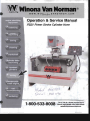
Operation & Service Manual
PS2V Power Stroke Cylinder Hone
II/ode l
S:c"V"la..\
8G685 7
I ~-6 1196
1-800-533-8008
710 E. 17th Sl Wichita, Kansas 67214
Phone; 31~219-3500 Fax: 316-219--3510
salesOwlnonavannorman.com
Pa rt No.
D 8 66837 .................. 23 0V. 60 Hz. 1 Ph
D 8668 29 ....... ......... ..230 V. 50 Hz. 1 Ph
Serial Number _ __ _ _ __ _ __
Purchase Date __________
Purchaser's Name _ _ __ __ _ __
Address _ _ _ _ _ _ __ _ __
Set-Up Date _ _ _ _ __ _ _ _ _
Set-Up By _ _ _ _ _ _ _ __
ABOUT THIS MANUAL
Knowledge of and compliance wilh the operatio nal and
service principles ou tlined in this manual are esscnli al
for operation of your machi ne. Maximum benefit will
be ga ined from the initial set up and training session
if all prospective operators have read and are familiar
with this manua l before the technician arrives. The
more you know about your PS2V Power Stroke Cylinder
Hone - the more profitable it wi ll be. Please specify
the Model and Serial Number of the machine in any
correspondence refurring to this machine .
If any problems relative to operation or service
should arise, contact Winona Van Norman direct, os
we ma inta in personne l whose purpose is to to ke care of
co nditions relolive 10 eiUler service or production which
mighl arise,
AWARNING •
LIMITED WARRANTY
W VN ....naRlS ror • period or
IlIOIIlhJ from dale 01 N'Ilpmcnl by
WVN 10 lhe. oriaioal pun::hM:r r'Buya'")
INII equipmmt manufa.111Rld by WVN
...iII be f_ from MrcIlI in ~-'"
~p " 'haI ill!ll.lllcd _openleel
in aooordana: ... idl I.tw incWuctJunI; in
!he equ ipmmr: manual This..amnty
IwcJ~
does not co.u ...,. f.ill",. due 10:
I«iderll; modirocatioo; I.... pr"n';
abu,.,; ......... ~ .00 lear, shippin,
cia"",,,; deleriorloU<>oo or wear ~
by ~iCJII'; .tnsion. corro.ioa. or
erosion; improper- erection; ~ioo
or mainlerulna:; abooormal condilion, 01
lemp:nuun: or din; go opCnIion 01 lhe
cquip""'DI &boYc riled Clpacilioes or in an
oxh_ l"" improper ,"",n~.
If ",iUlin lhe ooe·ye~r "'ll11Inly
period WVN rtteives wrinen noUcc at 71 0
E. 17th Sln:r:t. Wkh it:l. KJons.s, 67214.
p<umplly aftcr dbawr;ry by Ouycr uf
any dl:fea In 1ll.lIenal or VoOrkmaAAhip in
Ihe cqulpmcm ....rranwl b~ WV N he..,in.
WV N lJIaIl. .. lu sole <)pilon. ei lher
.., place (f.O.O. WVN·s planl),
!kfcctivc pants). If the
..
Of
"'pooi,
•
""'"
def~'CIj,'C
:~,~u:~.,~,~;~~, ;,;_~~';'.~'
Ix pronm,d
Dr compont nlS
nI)I manufae'lun:d by
WVN, c:tUT)' onl}' die WlI/llUltJe$ &i~en I')'
lie ~pectJ~maaufaclUn:n1hcrrof ... hid!
~1lCS. WVN will nUlk ~ .~ul.ble In
Buyer 10 the ~l permissible ... lllooot
pszV, 13/06
•
Unpackin8 and Setup of PSlV ..................................................... J Installiog and Assem bling Hooe Head ........................................ J ElectricaJ Requi rements ................................................................ J Loading Engine Blocks into Ma chine .......................................... 4 Adjusting Honing Stroke.................................................•............. 5 Basic Operation ............................................................................• 5 Determinin& Cylce Rate Bued OD Crou lIeild A.ugle ud RPM ................... 5 Parts Drawings .........•....•.........•..•........................................... 6 • 1 8 Electric a l Schematic A£semhlies ......................................... 19 - 20 Maintenance ................................................................................ 2 i 866699
866890
666891
866936
80468'
666939
667206
804631
SPECIFICATIONS:
OPTIONAL EQUIPMENT
Maximum Block Length: in. (mm) .................................. 42 (l06U) Maximum Slrok.e with powered feed : in.lmm) ............... 14 (356) (manual feed): in.lmm ) ............................................. ...... 16(406) Honing Ronge with standard equipme nt: in. (mm)2.7-5.5 (69-140) (with optio lla l equipmont): in. (m m) ................... 1.5-7.0 (38-177) HOILI:! Malar: lIP ............................................................................. 2 HOLLing Speed (infinitely varinblfl ): RPM ......... ................. 120-240 Stroke Molar: tIP ...................................................................... .0.33 Stroki ng Speed (infinlloly variable): SPM ............... ............. 9-105 Coolant Capacity: ga llous (lite rs) ...................................... 65 (246) Coolant Flow: spm (Ipm) ........................ .... .......... ........... 13.5 (51) Machine Length: in . (mm) ............................................... 68 ( 1727) Machine Widt h: in . (mm) ................................................ 60 (1524) Machine HAight: in . (mm) ............................................ ... 70 (1778) Door Opening: in . (mm) ........................................ .......... 48 (1219) Machine We ight: Ibs. (kg) .............................................. 1450 (657 ) Domestic Shipping Weight : Ibs. (kg) ............................ 1600 (726) Export Sh ipping Weight: lb!!. (kg) ................................. 1850 (639) •
Hone Heads
Hone Head, 1S _2.2" (36-56mm) range
Hone Head, 2.0" -2.68" (51--69mm) range
Hone Stone Sets
' 70 Grit , 2 3 /4" - 4 1 /2 " (70-114mml Ran ge
"1 50 Grit. 2 3 / 4" - 4 1 /2" {70-114mml Range
220 Grit, 23/4" _ 4 1 /2" (70-114mm) Range
- 260 Grit . 2 3 /4" - 4 1 /2" (70-114mm) Rangc
400 Grit, 2 3/4" - 4 1/2" (70-1t4mm) Range
"70 Grit, 31/2" - 5 1/2" (89--140mm) Range
-1 50 Grit, 3 1 /2 " - 5 1 /2" (89-140mm) Range
220 Grit, 31 /2" - s1/r (69--14Omm) Rangc
- 280 Grit. 3 1 /2" - 5 1/2" (69-140m m) Range
400 Grit. 3 1 /2" - stir (89-140mm) Range
Other s izes Available to reach s ize 7.0.
KEEP THESE LABELS attached to the machine and legible at all times.
Replacements are avai lable from the factory.
ADANGER
AWARNING
Turn Oil And Lock Out
Keep CtOlhmg Hil"
Electrical Power
And Body ParIs
Be/ore Opening Door
Or RemOVing Cover
Oul 01 Rolitlln'] P.uts
PS2V. 12/06 COPYRIGHT
e 2001
Belts And Ge,Hor19
Part No. 862302
Pa.rt No. HI4485
•
Part No.
667095
667000
Part No .
604770
809772
863358
604774
863359
609771
604773
663356
604775
863357
Friction Feed · Ho ne HAad
Drive Shaft - HOlle Head
Hone Head, 2.5" - 5.5" (64-140mm) range
Ta ll Para lle ls' 2 Pes.
Short Para llels - 2 Pes.
Eogine Bar Clamp. Standard
Engine Bar Clamp, Heavy Duty
Coolant. 30 gal lons (113 liters)
Hone Stones. 6 sets
(see entries marked " below)
Part No. 86326]
Do Not Operate
Machine Without
Covers And Guards
Part No. 863266
Winona Van No rman W Wlnona Van Monnan o
Phone: 316·219·3500 Fax: 316·265·0013
710 E. 17th St. · Wichita. KS 67214
www.winonavannorman.com
1-800-533-008
1
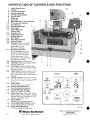
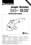
IDENTIFICATION OF CONTROLS AND FUNCTIONS 1.
2.
3.
4.
5.
6.
7.
8.
9.
10.
11.
12.
13.
14.
15.
16.
17.
18.
19.
20.
Cradle Raise & Lower
Parallels
Oil Flow Control Valve
Traverse Handwheel
Oil Filler (inside cabinet)
Control Panel
Head lock
Oil Nozzle
Main Fuse Box (on rear of cabinet)
0 11 Pump (inside cabinet)
Oil Drain Plug
1
Index Release Handle
Drive Head
Stroke Adjustment
Access Door
Universal Joint
Bi-Dlrectional Hone
Friction Feed Unit
Drive ShaH
Hone Head , Standard
Stones & Guides
Emergency Stop: Thrn knob
14
_
•
- - -13
6
9
4
to supply power to machine.
push knob 10 SlOp all
function s of machine.
' - - - 10
21 . Oil Pump On/Off Auto:
Se lect between manual and
automatic function of the oi l
pump. On a llows lhe pump
to run con tinuous ly. Auto
activates the pump on ly when
the machioe is cycli ng_
22.
Cycle Start: Begins hon ingcyc le.
23. Cycle Stop: Sto ps hon ing cycle before
cou nter reaches zero.
Cycle Dwe ll: Stops the stroke at any
poi nt in t.h e cycle while the hone head
cont in ues to rotate.
25. Cycle Counter: Sets the number of full
cycles des ired for a honing operation.
(one cycle includes both a down and u p
mot ion)
26. Honing load Meter: Shows amount of
current being drawn by the hone motor.
This a llows consistent loading of Ule
stones.
27. Hone ON/OFF:
Turns hone motor on and off.
28. Honing Speed Adjustme nt:
Infi nite ly variable honing RPM.
29. Honing RPM Digital Display:
Shows actua l hone head RPM.
30. Stroke Jog Button: Each push of Ulis
button cycles t.he drive head to the next
posi ti on following a sequence of TOP
11
8
24.
@
~ .-
-- ' ..... 1'01 ' ....
--
.~,
CYCLE
~-
.~
- 0
@
.
.
t . cu CO<.on ••
.
,
HONE
I @
~
~'G) --@
@ @
'WI. Winona V... Morman"
710 E 17th St. · WlChila, KS 67214
32
I
@
31.
2
3
STROKE
Mll)OLE . BOTTOM · TOP.
Stroke ON/OFF: Co ntro ls power to stroke concrols. 32. Stroke Speed Digita l Display: Shows Rctua l strokjng speed i.1I cycles/min . 33. Stroke Speed Adjustment: Infinitely variable stroking s peed. •
2
8
_lOA.
I
29
--
I
e
;.
@
!.;~~.J
~,
. .
PS2V, 12106
Phone: 3 16·2 19·3500 Fax.: 316-265-0013
1·800·533-008
www.wioonavanoorman.com
•
cabinet and on skid. Verify standard equi pmen t
agai nst equipment lis!. •
2. Take machintl off skid. Place machine so there
is adequate clearance in fron t for load ing and
unioad ingo fparls. There should also be clearance
for access to lhe back of the mach ine. The hone
should sit nat on the noar. S him the high corner,
if necessary, 10 achieve a solid fOO l ing.
3. Take blocking fro m head assembly or remove bolt
from back ra il of hone.
4. Pu t coolant p ump in coolant pan .
tbe two set screws securely. Check the four set
screws Lhat hold the U-joint to the gear motor to
be sure they are tigh t.
2. Assemble t he hone head to the d rive s ha ft ri ng
us ing the two button bead cap screws and spacers
attached to tbe hone h ead.
3. Mount Dri ve Shaft/Hone Head assembly to the
Friction Feed unit by sec uring the Drive s haft
collar. Be sure the square shaft and dri ve pi n are
p roperly engaged.
4. Insta ll tbe Stones and guides into the Hone
Head . Be sure to install them so the rack teeth are
toward t he (:enter an d inserted from th e side with
the "X " .
5. Add honing o il to machinll 8602 63 - 30 Ga llons
6. Assemble hold downs to crad le.
ELECTRICAL REQUIREMENTS
INSTALLING AND Machine req uires 220V, 60 Hz. 1 Ph 4 wire electrical
sup pl y. Have a qua lified electrician wire machine
into 20 amp (minimum) supp ly.
2
5
•
3
CRADLE
3
HOLD DOWN ASSEMBLY
Item
Part No. Description
Customer Sup p lied Cable
Oty.
1
8 101 32 Clam p Rod .......................... 1
2
3
14 1950
808750
Jam
4
5
808744
866954
867312
ELECTRICAL SHUT OFF ASSEMBLY
Clamp Bl ock .............. ......... 1 Item Pa rt No. Descriptio n Fla nge Nu l .750-10 ............ 1
Nut .750-10 ................. 2 Washer ................................ 2 t
2
3
•
PS2V.12106
Wi. Winona Van Norman" 710 E. 171n S1. · Wichi1a, KS 67214
4
5
6
7
8
9
10
864874
862306
862881
804 881
809607
809606
814365
801475
8014 71
866793
Qly.
Remote Shu toff Swi tch .. ... ... ............ 1 Fuse 15 Amp ................. .... .. ... .......... 1 Fuse 20 Amp .. ...... ... ...... ........ .. ......... 1 Flex. Conv. Hose .75 ................... 120.. COlUlector 90 0 •••• . •• . ••.•• . •• . •••••.•••••••••••• 1 COlln ector Sir.................. .................. 3 Cab le 22 I 4 ............................. .... 300.. Wire Nut ........................................... 1 Slrain Relief.......................... ..... ..... .. 1
Lock Nul ........... ................... ........ .... 1 Phone: 316·219·3500 Fax: 316·265-0013
1-800-53J.008
www.wmonavannorman.com
3
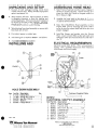
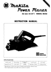
LOADING ENGINE BLOCKS
INTO MACHINE
Positioning ParaJlels for 'nlioe and "V" Blocks.
1. If cngine blocks ma in bearing centerl ine is in li ne
with its pan ra ils. (Figure 1), position Parallels
upward (Figure 2).
CLAMPING ENGINE BLOCK IN PLACE
(INLINE AND " V" BLOCKS).
NOTE: AI loast t bo two ond bearing caps must be
bolted in p lace. Distortion will be kepi to a min imum
if aU main bearing caps are installed and torqued
properly.
1. Pineo Clamp Bar Lhrough main bearing bores
(Figure 5).
2. Move carriage to the left and raise the d rivo head.
3. Mako sure that the pan ra ils do not have any gasket
material or dirt on them.
4. Slide Parallels to approximate position ncar the
en ds of the en gi n ~ block.
•
Figure 1
Parallels
Clamp Bar
Figure 5
5. Place the engine block on the paraJJels near the
center of the Cradle (Figure 6).
PIC 1111
Figure 2
2. If main bearing cen terline is above pan rails,
(Figure 3) turn Para lle ls to the down position
(Figure 4). If tho bearing ceoterli ne is more
than 3 inches above tho pan raj[ then use the
short para ll cl set. When properl y positioned the
bearing centerli ne shou ld be approximately in
lino with tho pivot axis or tho crad le.
ell
(Ja c
11 11 11 11 Iilll[')
• • • ~£.~
•••
. . . . . . .. .
~\~-.- ." -'~=
~
•
'-
Figure 6
6. Slide the Hold Downs into the Clamp Bar slots. It
may be necessary to shift the position of the engine
block so thai both Hold Downs will slide into the
slots of the Clamp Bar.
7. With both Hold Downs in position. tighten damp
nu ts even ly. first by han d and then w ith wrench. so
that engin e block is huld fll'mly to Crad ic. NOTE:
DO NOT overtighten. Inline Engine Blocks are now
in a position to be booed .
•
Figure 3
4
Figure 4
POSITIONING " V" TYPE BLOCKS.
1. Release cradle ind ex latch a t the left eod of the
Crad le and rotate the Cra dl e and engi ne block to
position for hon ing. The first notch from the cenler
position is for 60' "V" b locks; the second n otch is
for 90' "V" blocks.
"V " Engine Blocks are now in a position to be
honed .
PS2V. IU06
•
•
ovcrtravol a1 the Io.p of Uie cylinder. If It is possible
to overtravcl tho bottom then additional ovortravel
distance should be added. For 4~ stones approximately
.7 5" of ovcrtravel is required.
2. Release tho Drive Head lock and carefully lower the
Honing Head into the cylinder bore. Be sure the stones
are retracted enoug h to dear the bore diameter. Clamp
the Drive Head socure ly in the lowered position. Lower
th e cradle so that on ly 1-2 Inches of the stone am in tho
bore.
3. Tum main PQwer on, release the Eme~cncy Stop switch
and sill tho Stroking speed to "2", Thm stroke on and
momentarily push the JOG button and releaso. The
Drive Head wfll move down to a horizontal position.
4. Opcn access door to stroke selti ng plate. Usmg tho 1/4"
hex WTanch supplied adjust the stroke.
5. Loosen the stroke lock by turning the top ca p screw
about 1/2 tum CCW
6. Turn the lower cap scrow to adjust the stroke. The fron t
edge of the Sliding Illock indicutes the stroke sotting on
the scales. (This IS viewed from the righl side 01 the
Drive Head ) NOTE: uach fu ll tum of the screw changes
the stroke 1/ 4".
7. Tighten the stroke lock by turning the top cap screw
un1i1 snug. It is not necessary to lighten more than 5
ft-Ius.
8. Remove h ex WTonch.
9. Momentarily Rush the JOG button then release. The
Drive Head WIll stop at tho bottom position. Raise the
crad le unti l the stones are positioned at the bottom
of the cylinder or be low the bottom if overtrave l is
!'C<)uired.
10. Jog Drive Head to the top to verify that the top overtravel
IS correct. If necessary ropeat the stroke setting proccdwe
until proper travel is achieved.
•
BASIC OPERATION
Power Stroke Honing
1. Lower Hono head into cylinder and expand stones to
within il few tlJousandths o f the cylinder diameter.
Clamp Drive Head in lowest position.
2. Release cmurgency stop switch. select "AUTO" oi l
pump aud turn stro ke "OFF".
3. Sc t c,rcle counter to d esired number of cycles. twn Hone
"ON . nnd select Honing RPM. (Honing motor does nut
need to bo runlliu~)
4. Sat strokJ n~ sp~il at 3-4 on the potentiometer scale
tum stro ke 'ON", push cycle "START". Thl! Hone wi! j
sturt full oporulion at Ulis POiDt. Readjust stroke speed
to desired setting.
Manual Hon ing
1. With Stroke "ON" and HaDe "OFF" jog head to lowest
pos ition .
2. Th.rn Stroke ·'OFF". set Cycle Counter to 1.
3. Release Drive Head Clamp.
4. . Press Cycle Start.
Raise and lower Drivl) Head
manually.
USING THE FRICTION FEED HONE HEAD
•
1. Ho lding the up'Qcr fricti on food ring will ex-pand the
stones, holding Ute lower ri ng will retract the stones.
2. The Honing LOad meter wi II show how hard the stonos
arc working. It will also indicate how straight the
. bore. Readmg within one amp on the meter indicates a
• stra ight bore.
3. If the load reading nu ctuates more than one division.
, iake note at what point in the cycle the readings are
highest. A high reading indicates a tight sppt 10 the
oore. By usinglhe "DWELL" button. it is posslble to Tun
the stonos in ono p lace to selectively remove addiUonal
stock
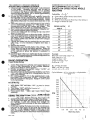
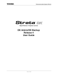
AND RPM
Cycles!M.in. = K x D x R
L
K = Cross Hatc h Angle Constant (Sec Chart)
D = Diumeter of Bore
R =RPM of Hone (Based on Bore Dia.) (Sec below)
L = Length of Stroke of Stones
CROSS HATCH
ANGLE
K
10'
15'
20'
25'
30'
35'
40'
45'
.137
.207
.277
.348
.421
.495
.572
.65 1
Example: Required cross hatch angle = 20' Bore diameter = 3.5" Length of bore = 6.0" Length of stones =4.0" Overtravel = .75" K = .277 for 20· CHA RPM = 197 for 3.5" Bore L =6.0 - 4.0 + .75 = 2.75 Cycles/Minu te = .277 x 3.5 x 197 = 69 Cycles/M in .
2.75
250
240
230
220
210
200
190
RPM
180
170
160
150
140
130
120
:
2.5
3.0
3.5
4.0
1
t
4.5
5.0
Bore Dla. (Inch)
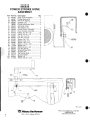
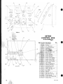
866838 POWERSTROKEHONEASSEMB~
Item Part No. Description
1
2
3
Oly. Control Box Assembly (P. 17.18) .. 1 OC Gearmotor Assembly (P. 14) ... 1 AC Contro ller Assembly ............... 1 Coolant Pump Assembly ............... l Electrical Shut-Off Assembly (P. 3) 1 Crad le Assembly Wcld ment ... ...... 1 Hon e Tank Weldment. .... .... .... .... .. . 1 Tank Wcldment Door .................... 1 Idler Plate Assembly ..................... 1 Pivot Arm Assembly ... .................. 1 Power Head Assembly ... .. ............. 1 Motor Cable Assembly .................. 1 Oil Filter Assembly (Page 9) ......... 1 Str. Cam Assemb ly {Page 13) ........ 1 Supp. Slide Assembly (Page 16), .. 1 L.H l.eadscrew Assembly (P. 11) ... 1 RH Leadscrew Assembly (P. 12) ... 1 PH Base Assembly (Page 10) ........ 1 PH Cover Assembly (Page 15) ...... 1 Flange Hub..................................... l Un iversa l Joint ............................... l Gearmotor ...................................... 1 Ball Bearing .......................... ... .... .. 1 BH Locknut. ...... ...... ....................... 3 Flange Bearing 1...... .... .... ........... .... 2 Flange Bearing 3/4" ....................... 3 867000
867277
4
867280
867162
5
867275
6
7
8
9
10
11
12
13
14
15
16
17
18
19
20
21
22
23
24
25
26
866926
866040
867040
866933
867086
867010
867268
867271
867276
667201
867273
667274
867272
867279
860749
866884
867212
866874
866872
866869
866868
Item Part No. Description
27
28
29
30
31
32
33
34
35
36
37
38
39
40
41
42
43
44
45
46
47
48
49
50
51
866867
666866
866865
866864
866863
801240
866941
866942
806022
806023
867022
866956
866946
866949
866974
866993
867085
867097
867013
801591
801562
801613
801604
817949
866995
Oly. Fla nge Bearing 3/4" ....................... 1 Pillow BI. Beariog ... .... ......... ... ...... 1 Sprocket 11 T ........................... , .... 1 Sprocket 14 T ... .. ........................... 3 Sprocket 16 T ......... .......... ............. 1 Lead. HandwheeJ... ........................ 1 Cradl e Handwheel Shaft ............... 1 Handwhccl Shaft ........................... l #40 Roller Chain #40 Master Link. ............ ............. .... 4 PH Counterweight ................ ......... 1 Cradle Pivot Spacer .... ............. .... .. 1 Thrust Bearing ................. .. ............ 1 Crad le Hand le Assembly .............. 1 Cha in Hookup Assembly ....... .... ... 1 Str. Operat. Rod ......... ..... ...... ... ...... 1 Pivot Shaft ............ ........ ... .. ........ .... 2 Pivot Arm Base ............. ... .......... .... 1 Pivot Pin ....................... ................. 1 Hex Nut .625-11 Jam ..... ...... .......... l Was her Sr..625 ......... .... ...... ........... 1 HHCS .500-13 x 1.25 ..... ................ 5 LC Washer .50 ...... ........ .................. 3 SHCS M12 x 35mm .... ........ .......... .1 BHCS M12 x 30mm... ........ .......... .. 1 •
•
,
,
, .J
6
PS2V, 12106
•
POWER STROKE HONE ASSEMBLY
•
Item
52
53
54
55
56
Part No.
603024 804735 811237 801625 805324 57
803082 58
59
60
61
62
801637
801023
801661
803061
801601
63
109391 64
65
66
67
68
804747 866904 114160 801478 866805 69
866888 70
866992 71
72
73 74
75
76
77
804764 808374 8024 22
809018
814566
867023
Description
aly.
Was her Flat .50 ..... ........ ................. 5
HHCS .3IZ· lax 1.00 ............... ..... 10
HHCS .375·16 x .75 ....................... 6
HHCS .375-16 x 1.00 .................... .4
HHCS .437·14 x 1.0 ...................... .4
Hex Nut .312-18 ............................ 1
Hex Nut .375·16 .... .... ..... ............... 2
Was her Flat .375 ........... ............... 12
Washer Lock .312 ..................... ..... 1
Washer Lock .375 ........................ 10
Washer Flat .314 ......... ................... 1
SHCS .312-18 x .875 ...................... 2
HHCS .312-18 x .875 ..................... 2
HHCS 1.00-14 x 2.00 ..................... 2
Washer #10 ................................... . 8
Cable 16/4 Std ............................. 8"
Se lf-Tap Screw #10-32 .................. 2
Washer Flat 1.00 1.0 ... .. ................. 2
SHCS .312-18 x 3 .00...... ................ 8
SHCS #10·32 x .375 ...................... 2
Hex Nut 1'10-32 ........................ ..... 1
Woodruff Key #304 ....................... 1
Woodruff Key #605 ... .................... 1
Ker .187 x .187 x .875 ............. ...... 2
Sll'IppCr Bolt .750 .................... ...... 1
Item
78
79
80
61
82
Part No.
867041
866945
867987
614700
867207
Description
a ty.
Sp rocket 9 T .................................. 1 Traverse HD Shaft.......................... 1 Hex Plug 3/4 NPT.......................... 1 Urethane Tube .625 ....................... 5 Tank Screen (Set )........................... 1 867253
804716
867217
867256
861816
801471
866793
801 469
801622
804765
866860
866859
813927
105288
867230
813398
867218
802413
813498
809606
Gauge Holder ................................. 1 ToorHo lder Rack ........................... 2 Sprocket Shaft ............................... 1 83 84
85
86
87
88
89
90
91
92
93
94
95
96
97
98
99
100
101
102
103
Coolant Pump Pan ......................... l Shaft Key .............. .......................... l Sta in Relief 1/2 NPT ..................... 1 Lock Nut 1/2 NPT ......................... 2 Strain Re lief 1/2 NPT .................... 1 HHCS .375-16 x 1.7 5 ..................... 4 BHeS #10-32 x .62 ........................ 2 Timken Cup Bearing ...................... 1 Timkell Cone Bearing .................... l Washer 1.00 x 2.00 ........................ 2 Washer .437 ................................... 4 Mounting Kail ................................ 1 Termina l Block ........ .................... 18 Din Rail Cl ip .................................. 6 Washer .25 ..................................... 1 HHCS .250-20 x .375 ..................... 1 Stra in Kelief 3/4 NPT .................... 1 •
•
•
I'S2V.I2106
~IG HT
EN' VIE V
7
866838 POWER STROKE HONE ASSEMBLY
Item
15
27
28
30
31
33
35
36
40
41
53
54
57
58
Part No.
867281 866867 866866 866864 866863 866£141
806022 806023 866949 866974 804735 811237 803082 801637 59
801023 60
61
63
66
801661 803061 109391 114160 71
804764 72
75
76
85
86
101
102
608374 809018 867041 804716 867217 802413 813498 •
Qty. Supp. Slide Assemb ly ................... 1 Flange Bearing 3/4" ....................... 1 Pil low BI. Bearing ........................ .1 Sprockel14 T ................................ 3 Sprocket 16 T ....................... ... ...... 1 Cradle Handwheel Sbaft ............... l 1140 Roller Cha in #40 Master Link ........................... ..4 Crad le HAndle Assembly .............. 1 Chain Hookup Assembly .............. l HHCS .J12-18x 1.00 .................... 10 HHCS .375-16 x .75 ....................... 6 Hex Nul .312-18 .............. ...... ... ..... 1 Hex Nut .375-16 ............................ 2 Washer Flal.375 .................. .. ...... 12 Washer Lock .312 .......................... 1 Washer Lock .375 ........................ 10 SHCS .312-18 x .875 ...................... 2 Washer 1110 .................................... 8 BHCS NlO-32 x .375 ...................... 2 lIex Nut 1110-32 •.... ........................ 1 Woodruff Key 11605 .......... ... .......... 1 Sprocket 9 l' .................................. 1 Tool Holder Rack ................. .......... 2 Sprocket Shaft ............................... 1 Washer .25 ..................................... 1 HHCS .250-20 x .375 ..................... 1 Description
•
.,
•
<i'£J
-.v
•
f'S2V.I2100
l!!L Winona Van Mutlllal'l°
8
710
e. 17th St. ' WIChita, KS 67214 Phone: 316·219·3500 Fax: 316-265-0013
1-800-533-008
www.winonavannorman.com
•
867271
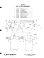
OIL FILTER ASSEMBLY
•
Item
1
2
3
4
5
6
7
8
Part No.
Description
867138
867142
Filter Support Bracket ... ... .. .......... 1
Filter & Adapter ............................ 2
Tee .50 NPT .................................. . 2
Pushloc k Filting ............................ 4
Reduci ng Bushing ......................... 4
Elbow 90° .50 NPT ........................ 3
HHCS .312-UI x .750 .................... 2
Washer FI. .314 x .75 .................... 2
Washer Le.. 312 x .57 ................... 2
Urethane Tube .625 .... ................ 18"
Nipple P .50 NPT .......................... 3
Repl acement Filter .... ..... .. ............. 2
B07]67
867141
867140
801479
806241
801601
801661
814700
9
10
11
12
801386
867143
Qty.
"-
•
o
o
o
--~;.--,cu-~
o
,
.,
"
•
P5ZV, l2I06
•
Winona V.. Noth..."
7 10 E. 17th 5 1.' WiChita, KS 6721 4
Phone: 316·219·3500 Fax: 316·265-0013
1-800-533-008
w-NW.wmonavannorman.com
9
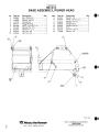
867272 BASE ASSEMBLY, POWER HEAD
Item
1
2
3
•
5
6
7
8
9
10
Part No.
867012
666985
140695
14 2174
667021
801616
601023
603061
801637
803082
Description
Oty.
Base Weldment .......................... 1
Bar Weld ln e nt ............................ 1
Was her .50 H.D.......................... 1
Hand le K/E ................................. 1
Flange Bearing ........................... 2
H}lCS .375-16 x 1.25 ................ .4
Wash er Flat .375 ....................... .4
Washer LC .3 75 .......................... 4
Hflx N ut .375 .. ..... ... ................... .4
Hex N u t .312 .... ... .... ................... 2 Item
11
12
13
14
15
16
17
18
19
Part No.
801601
804444
807868
866876
867025
866870
867216
803342
105286
Description
Qty. Washer .314 ................................ 3 HHCS .3 12-18 x 2.5 ................... 3 Jam Nut .43 7-14 ............. ............ 1 Whccl .................................... .... .. 3 Str ipper Bolt ............................... 1 Nood le Bearing ........................... 1 •
Axle ............... ............................. 1 Hex Nut .437-14 ......................... 1 Washer .437 ...... ..... ..................... 1 ,
10 II
i
,
,
II \~
n
•
,
PS2V.1ZI06
Wi. Winona Van Noiillilll"
10 710 E. 17th $1.' Wichita. KS 672 14
Phone: 3 16·2 19-3500 Fax: 316·265-0013
1-800-53:Hl08
www.winonavannorman.oom
•
•
LEADSCREW ASSEMBLY (LEFT)
~em
1
2
3
•
5
6
7
6
•
10
11
12
Part No.
866853
866855
866918
866920
866859
866860
866861
867282
866872
866888
866955
866957
Description
QIy.
Leadscrew L.H ........................... 1
Bearing Mount Block ....... .......... 1
Crad le Mounting B lock .............. 1
Cradle Block Nut. ....................... 1
Beating (Cone) ............................ 1
Bearing (Cup) ............................. 1
Ball Bearing ................................ l
Sprocket. ..................................... 1
Locknut. ...................................... 1
Washer 2.50 ................................ 1
Pivot Stud ................................... 1
Camp. Spring ............................. 1
Item
Part No.
13
1.
15
16
803649
866958
866959
866960
,.
17
801568
16
801640
804523
801616
809018
801656
801610
801599
20
21
22
23
2.
Description
Qty. Stripper Bolt .50 ..................... ... . 2 Crad le Lock Assemb ly ........... ... . 1 Crad le Lock Assemb ly ............... l Knob ........................................... 1 IfriCS .250·20 x .75 ................... 1 SHCS .250·20 x .75 .................•.. 4
Washer .250 ................................ 1 Washer LC .250 ...................... .... 1 Woodruff Key #605 .................... 1 Grease Zerk ................................ 2 SHCS .375-16 x 1 ....................... 1 SHCS .375-16 x 1. 25 .................. 1 ""\
•
867274 LEADSCREW ASSEMBLY (RIGHT)
Item
1
2
3
4
5
6
7
6
•
Part No.
866857
866856
866919
866920
866859
866860
866888
866872
@-
I'S2V. I2I06
Description
QIy.
Leadscrew R. H........... ................ 1
Beariog Block R. H...................... 1
Cradl e Block R. H........................ 1
('.ladle Block Nut... ..................... 1
Bearing {('..one) ............................ 1
Bearing (Cup) ............................. 1
Washer 2.50 ... ............................. 1
Locknut BH ................................ 1
Item
•
10
11
12
13
14
15
16
Part No.
866861
867282
801640
801568
804523
801616
809018
801656
Description
QIy. Ball Bear ing ..... ........................... 1 Sprocket. ..................................... 1 SHCS .250-20 x .75 .................... 4 IfrlCS .250-20 x .75 ................... 1 Washer .250 ... ............................. 1 Washer LC .................................. 1 Wood ruff Key #605 .................... 1 Grease Zerk .......... .. ............... .... . 2 I
<1>'
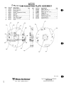
11 867276 STROKE CAM ADJUSTING PLATE ASSEMBLY
Item 2
Part No.
867035 867082 3
867076 4
5
867080 6
867209 7
867036 867208 9
10 867099 1
•
866902 867137 Descrlpllon
Qty. Wheel (Mach.) ............... .. ............ .. 1 Block Assembly ............................ 1 End Block ...................................... 2 Stroke Adjustmen t Clamp ............ 1 Bushing .......................................... 1 Spacer ................. .. ..... .................... 1 Cam Plate ........... .. ............ ............. 2 Cam Plate (Large). .......... ............... 1 Shaft Assembly .......... .. .... ........... .. 1 Scale .................... .......................... 1 Item 11 12 13 14 15 16 17 ,.
19 Part No.
801609 603996 864965 667061 867078 111539 802087 867004 867249 Description
Qly.
SHCS .250-20 xl ....... .. ................. 6 SSS #10-32 x .62 ....................... .. .. 2 SHCS .312-16 x 2.25 ..... .......... .. .... 1 Clamp Pin .......................... .. ..... ..... 1 Screw Retainer .............................. 1 SSS #10-32 x .25 .......... ... .. ..... ...... . 1 FSHCS .25-20 x .50 .... ................... 6 Adjusting Rod ...................... .. ... .... 1 SHeS #10-32 xl ........................... 2 •
,
•
o
•
,
PS2V.1 2/00
W. Winona Van Motm..•
12 710 E. 17th Sl • WICh ita , KS 67214 Pnone: 316 '219 -3500 Fax: 316-265-0013
1-600-533-008
WWN.winonavannorman.com
•
GEARMOTOR ASSEMBLY •
Item
Part No. Description
ety. Gear Red ucer ..................... . 1 1
866882 2
3
4
66 7309 Reducer Base ..... .................. 1 667676 81 4403 D.C. Motor ....................... .... 1 5
866873 6
866903 866862 604881 7
B
9
10
86 7005 801 4 71 11
866793 12
13
14
8014 78 801660 806245 Connecto r 90° ...................... 2 C lutc h Brake .... ... ... ... ........... 1 Sensor Sw itc h (NCI......... .... 1 Sensor Sw itch (NO) ............ 1 Fl exable Hose ....... ............. 5" Sensor Picku p We ldment ... 1 Strain Re lief ... .. .... ... ............ 1 Lock Nut. .. ... .. .... ... ... ..... .... .. . 3 Cabl e 16/ 4 STO ......... ..... . 12" HHCS .312 -18 x .50 ... ......... 2 FS HCS 312 -18 x .50 .. .. ........ 4 "
•
STl.OS & fII\JT S SUPPLIED WIBRAKE
TO BRAI<E
t~J~~~"'~~l·Jtl~[t=rJ
Ttl
""ITt:
TO TERMINAL STRIP
~
I!(D
BLA
D.C. ItGTCJI !DiN.
JU'>lCT ION BOX DETAIL
•
PS2V, 12106 W!!1. Winona Van "Oilillan·
Phone: 316·219-3500 Fax: 316-2£5-00 13
1-800.533-008
~.winonayanno(man .com
710 E. 171h 5 1.' Wichi1 a. KS 67214 ••
13
867279
POWER HEAD COVER
ASSEMBLY
Item
Part No.
I
867011
2
3
4
867135
867136
114160
5
6
7
8
9
807142
8014 69
866793
860596
867267
10
1293 40
•
Description
Qty.
Cover.......... .................................... 1
Vie"'Port ............ .................... ........ 1
Door ...................... ......................... 1
Wasbe r #10 .................................... 6
Hex Nut #10-24 ............................. 5
Stra in Reli ef .................................. 1
Lock Nul .... .... .......... ...... ....... ... .. .. .. 1
Stripper BolL. ........... ..... .. ....... ...... . 1
Bellville Washer ............ .. ..... ... ..... . 2
SHeS #10-24 x .37 5 .... ..... ..... .. ...... 4
,
@)
/
•
•
•
,
:5 10 4
View A
•
,
View A
I'S2V, 12/00
VJ!l. Winona Van MOilll...•
14
710 E. 17th SI. • Wichi1a, KS 672 14
Phone: 316·219-3500 Fax; 316-265 -0013
1~80I)..S33-OO8
WWoN.winonavannorman.com
•
SUPPORT SLIDE ASSEMBLY •
Item Part No. Description
aty.
1 866910 Support Housing A'bly ................... . 1 2 804806 BaJJ Valve ......................................... 1
3
4
5
6
7
8
9
10
11
866671 Oil Seal ........ ........ .............. ... ..... ....... l
8071 12 Pipe Plug ....................................... ... 2
866979 Thbe Assemb ly ... ... ................. .......... 1
863141 HHQ) .375-16 x .62 .... ..................... 2
801636 Washer .375 ...................................... 2
867154 Nozzle Assemb ly ............................. 1
802264 Elbow .50 Br. ......... ...... ..................... 2
86714 1 Pushlock Fitting ..... .... ........... ......... .. 1
810038 Elbow .50............. ............................. 1
-
•
),
J:..l,
60
i!
r/
!
-
•
-i o
,,I
I
..--'-
i
r
:::: i
. EC
,~d_
,,i
!
I !,
i
i
i
i
t
I
!
~
v
L\
ri
o
,
,
•
•
,
•
LEFT END VIEW
•
PS2 V. 12/(16
'¥l!L Winona Van Norman·
7 10 E. 17th St.· Wic hita , KS 67214 Phone: 3 16·2 19·3500 Fax: 316·265·0013
1-800-533-008
www.winonavannorman.com
15 r'"'
•
/
o
L'
.J 1
I
HC~[
C'S2V
emr uu..u .,.sr_r
PIl'ol£'i
\
VlEWA·A
"
'-e
J
\
L
•
•
867000 CONTROL BOX
ASSEMBLY
Item
1
2
:3
4
@e 5
Part No.
867001
866880
860679
804725
864382
Description
Qly. Control Box .................... 1 Counter ... ................. ... ... 1 D.C. Controlle r ............... 1 Contro l Ampmelcr ........ 1 Knob Kit. ...................... .. 1 •
6 864455 RPM indica,tor ............... 2 7 813398 Tenninal Block ............ 15 8 862515 Relay 10 Amp 115V .... .. 2 9 867066 Relay Socket .................. 2 SECTIONB-8 16 10
11
12
13
14
15
16
17
16
19
20
21
22
23
24
25
26
27
28
29
30
867067 Switcb PH (NC) .............. l 867068 Swi tch PH (NO) ............. 1 867069 Switch PH (NO) ............. 1 867070
867071
867072
667073
613270
662306
814212
867144
867251
607137
601616
603016
667260
608374
601901
805850
867308
865367
Switch 2-Pes (2ND) ....... 1 Switch 3-Pas (2ND) ....... 1 Switch E-Stop 2NG. ....... 1 Switch 2-Pos UNO) ....... 1 Fuse Holder .............. ... .. 1 Fuse 15A FRN-R-15 ....... 1 Fuse 6A FRN-R-6 ........... 2 Control Box labeL ....... 1 Mounting Rail... ......... .... 2 HHCS .250-20X .50 ....... 1 LG. Was he r .25 ............... 1 Ball Knob ....................... 1 Hand le ............................ 1 Hex Nut #10-32 ........... 10 SHCS #10-32X .50 ....... 10 Poten tiometer ................ 1 Switch PB (lNC)(lNO) .. 1 Clamp Block .................. 2 PSZV, 12106 •
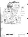
ELECTRICAL SCHEMATIC
" ~-r'~,--------o-----r-'--.----------.
• ..
-
.."•• .,
-.. r
"
I
,
,• •
.
"
-
,, ~
-
,~
~
on
I
.-,
••
•
".
I
..
1-.
~.
I
u
,
-
l
I •
~ ~
u
~
"
--L-: ___-"__-'.________L_______-"________-""-__J-__" __________________--"
----r'\....r-- •.•",
..
.--
-~
•
•• .
•• 0.'
Hem
51
52
53
54
5s
(INO)
56
57
56
PI
Description
E-Stop Switch Contact Block. (2NCI
PH Switch Contact Block U NCI
P8 Switch Contact Block: (INO)
2 Pos. Switch Con tact Block {lNOj
PH Switch Contact Block (1NC)
867068
PH Switch Contact Block (1NO)
3 Pas. Switch Con tact Block (2ND)
2 Pas. Switch Contact Block (2ND)
20 Amp Fuse
15 Amp Fuse
6 Am p Fuse
6 Am p Fu se
15 Amp Fuse
P2
867072
867070
862881
862306
P3
814212
F4
Fs
814212
RI
862306
601709
R2
801709
866880
erR
LSI
L52
666862
DROl
864455
OR02
POT
864455
866878
864379
805850
MI
8672 12
M2
867676
V5I
VS2
•
Part No.
667072
667067
867069
867073
667308
666903
PUMP 866687
BRAKE866873
•"
"
, •,
, •
, •
,
I
,• •
•
0
C:
0
0
-
"'-
F
'"
D.C VARIABLE SPEED DRIVE WIRING
-
•
.'~
.~ ~
.u
1
0
0
~,
Relay
Relay
Counter
Sensor Switch
Sensor Switch
RPM Indicator
RPM Indicator
AC Controller
OC Controller
Potentiometer
AC Ceannotor
OC Motor 1/3 HP,
1725 RPM, 180V
AC Cearmotor
Electri c Clutch Brake
T·
I~~ ••
c;-
m .
~
~
'---
u
~
-
-
••
.. o""n ••
u
"'U' ."
~
~
('
~
-
,
,
,
, •
, ••
~
~,
,•
~
,
N
~
"
.~
c:: ••
•
•
.,
A.C. VARIABLE SPEED DRIVE WIRING
P5Z V, 11/00
17
...
'.
~ 312
.,
ELECTRIC · . SCHEMATIC
.
:rf(i\
;
1;" I ..
,
,
"
~
I
~ II
1ft
if
~l-
/
I:':
_ "\.....1\
...
~
,
I .. ~
l
I;
•,.
\i
or
Vl( 'J Dr INTCRIIlR
CONTII'OL BOX
INSIDC VICIo' 01
(ON1RDL BOX
I"
•
\
,~ -/
vr.i:~ IJ
,. ~
flf
il"
T.
,
-t'
..
PS2V, 12106
lJ!J. Winona Van Not......•
18
•
."
• "
I~
~
vl'l'~
~~~~t/ I'
....
.......t.a_
I~~
..
.,
CO::
/'
~
-". L..,g.
710 E. 17th SI. • Wichita, KS 67214
Phone: 316·219·3500 Fax: 316-265-0013
1-800·533-008
www.winonavarlOorman.com .
•
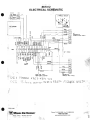
ELECTRICAL SCHEMATIC
•
I
I NO
PR{]X 1.51
INC
PROX LS2
J PHASE MOTOR
f-
D.C. HDTOR
__________________-r~·~(~D~r-
r
, ',/
r~------------------~~""~I~T(~r-
•~
•"
•c
I
16 - . C/IISLE
w
"
~
~i
I
w
w
•
~
>
~¥~
.
Iill =i
c
~~5
,v
AC
i-1L
CDNTROLL(R
(REMOVE BACK PI'oNEL>
________________~~·~~K~r-
c~
•" ••
c
w
"
•r
~
w~
RtD
~I ~
TJ2
16- . CAa LE
•
SH(iLD
n:..~
COHTRIJ...LI:R
V IllE C... 8I.. [
r lilDM ROCllE SaJTOfT
LS I
L<;;,
•
O rl\ R.ON
(II(1Cl VI: aACI( PAN[L>
G:;Z t= 1. -)(2. Yt - uS
TC,'(V\<e <..
Ill 'i U<"XS IIl'1 12
nlB:I..~G>
r,,'.4. (JJ(.t:
4 7,2..5,0&.10 J>S2V, I ZIU&
. .Winona Van MOllnan'
710 E. 17Ih St. · WIchita, KS 672 14
Phone: 316·219·3500 Fax: 316-265·0013
1-800-533-008
www.Wlnonavannorman.Com
19
MAINTENANCE
AND SERVICE
•
SCHEDULED MAINTENANCE
1. Weekly
Grease all fi ttings (Figure 11.
2. MonthJ y
Check wayaH in traverse Shaft Housing, Fill to
top o f ho us ing.
GENERAL MAINTENANCE
Figure 1
Oil
1. Change oi l filters (2 pes.) when honing oil now
rate gels low.
2. Before sed iment eets 1 1/2" deep in tank , change
honing oil. Remove Drain Plug from right side of
machine, dra in oil. remove sediment. wipe out
coolan t tank. install dra in plug, fi ll with oil (30
65 ga llonsl.
VENT
•
pi
Gea nnotor
1. The Sum itomo SM·Cycio gcarmotor is grease
packed and is maintena nce free .
Speed Redu cer
Dayton Spwd Reducer or
Alling-Lander Blue Max Speed Reducer
1. After in itial opera tion o f 100 hours. change oil
{when oil is warm l. Ulen oil shou ld be changed
every 2500 hours or ti months whichever comes
firs t. Refill with AGMA #8 gear oi l.
lJayton Magnetic Disc Drake
Il LEVEL
Dayton Speed Red ucer AlHng-Land er Blue Max Wa nn Over Approximate Oil Ca pacity 10 ounces, fill to oi l level p lug.
•
ACAUTION Loa d must be removed or hlocked . Brake will be inoperative during this procedure. "A"
Before air gap " A" reaches .100", adjustment is required .
Any de lay in adjusting the magne tic air gap will result in
eventua l loss of torque.
1. To adj ust . remove cover (Re f. 1) to expose adjusting
screws (Ref. 2) and magnet air gap "A".
2. Meas ure air gap " A" using 3/ 8" to l I z" wide feeler
gauge as s bown below.
3. 1\J.ro two square head set screws (Ref. 2) until air gap
" A" measu res:
.04 5/. 050 for 1 disc mod els
Air gap shou ld be tbe same on both sides.
•
20
PS2V.12/06