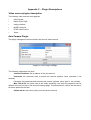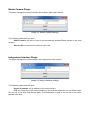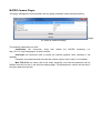
1
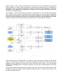
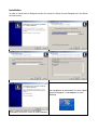
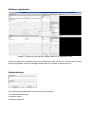
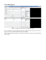
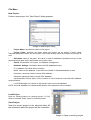
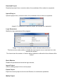
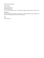
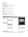
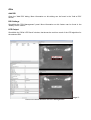
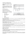
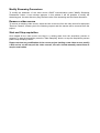
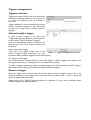
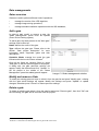
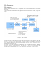
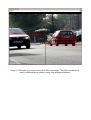
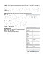
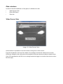
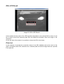
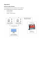
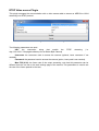
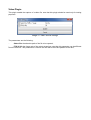
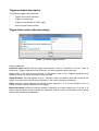
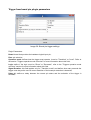
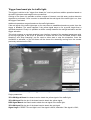
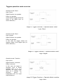
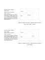
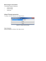
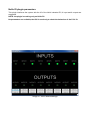
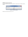
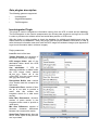
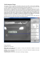
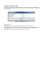
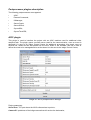
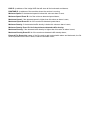
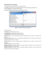
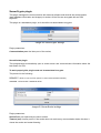
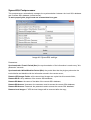
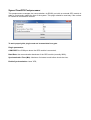
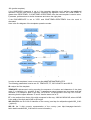
Innovis Designer 1.9.X
User Guide
Index
Overview .............................................................................................................................. 6
Software flowchart ........................................................................................................... 7
Installation............................................................................................................................ 8
Software registration ............................................................................................................ 9
Project Management .......................................................................................................... 10
File Menu ....................................................................................................................... 11
New Project: ............................................................................................................. 11
Load Project .............................................................................................................. 11
Save Project .............................................................................................................. 11
Download Project ...................................................................................................... 11
Login Parameters ...................................................................................................... 12
Import Project ............................................................................................................ 12
Export Project ............................................................................................................ 12
Close Project ............................................................................................................. 12
Update Registration ................................................................................................... 13
Information ................................................................................................................ 13
Device Settings .............................................................................................................. 14
Video Sources ........................................................................................................... 14
Video Source View .................................................................................................... 14
Boards ....................................................................................................................... 14
Triggers ..................................................................................................................... 14
Gates ......................................................................................................................... 14
Postprocessors.......................................................................................................... 14
ROIs .............................................................................................................................. 15
Add ROI..................................................................................................................... 15
ROI Settings .............................................................................................................. 15
LPR Output................................................................................................................ 15
Video Source Management ............................................................................................... 16
Add, modify or Remove a Video Source ........................................................................ 16
Add a Video Source................................................................................................... 16
Modify a video source ............................................................................................... 16
Modify Streaming Parameters: .................................................................................. 17
Remove a video source ............................................................................................. 17
Start and Stop acquisition.......................................................................................... 17
Boards management.......................................................................................................... 18
Board overview .............................................................................................................. 18
Add a board ................................................................................................................... 18
Modify a board ............................................................................................................... 18
Remove a board ............................................................................................................ 18
Triggers managements ...................................................................................................... 19
Triggers overview .......................................................................................................... 19
Add and modify a trigger................................................................................................ 19
Remove a trigger ........................................................................................................... 19
Gate managements ........................................................................................................... 20
Gates overview .............................................................................................................. 20
Add a gate ..................................................................................................................... 20
Modify and remove a Gate ............................................................................................ 20
Delete a gate ................................................................................................................. 20
Postprocessors managements .......................................................................................... 21
Postprocessors overview ............................................................................................... 21
Add a PostProcessor ..................................................................................................... 21
Modify a Postprocessor ................................................................................................. 21
Delete a Postprocessor ................................................................................................. 22
ROIs Management ............................................................................................................. 23
ROIs overview ............................................................................................................... 23
Add a ROI ...................................................................................................................... 24
ROIs Management ........................................................................................................ 25
Modify a ROI.................................................................................................................. 25
Remove a ROI ............................................................................................................... 25
Other windows ............................................................................................................... 26
Video Source View ........................................................................................................ 26
ROIs LPR Result ........................................................................................................... 27
Plate List ........................................................................................................................ 27
Appendix A......................................................................................................................... 28
Innovis suite schema ..................................................................................................... 28
Innovis Designer ........................................................................................................ 28
Innovis Runtime ......................................................................................................... 29
Innovis 7 Control Center ............................................................................................ 29
Appendix B ........................................................................................................................ 30
Sql database installation ................................................................................................ 30
Appendix C – Plugin Descriptions ...................................................................................... 31
Video source plugins description ................................................................................... 31
Axis Camera Plugin ................................................................................................... 31
Basler Camera Plugin ............................................................................................... 32
Indigo Interface Plugin ............................................................................................... 32
MJPEG Camera Plugin ............................................................................................. 33
RTSP Video source Plugin ........................................................................................ 34
Video Plugin .............................................................................................................. 35
Triggers plugins description ........................................................................................... 36
Trigger from motion detection plugin ......................................................................... 36
Trigger from board pin plugin parameters ................................................................. 37
Trigger from board pin for traffic light: ........................................................................ 38
Triggers operation mode overview................................................................................. 40
Board plugins description .............................................................................................. 42
Indigo IO plugin parameters ...................................................................................... 42
NuVo IO plugin parameters ....................................................................................... 43
USB Board plugin parameters ................................................................................... 44
Gate plugins description ................................................................................................ 45
Innointegrator Plugin ................................................................................................. 45
Traffic Integrator Plugin ............................................................................................. 47
SingleShot Integrator Plugin ...................................................................................... 49
Postprocessor plugins description ................................................................................. 50
ACIC plugin ............................................................................................................... 50
ExternalCommand plugin .......................................................................................... 52
IOManager plugin ...................................................................................................... 53
ServerCrypto plugin ................................................................................................... 54
ServerSocket plugin .................................................................................................. 54
SyncroSQL Postprocessor ........................................................................................ 55
SyncroTimeGPS Postprocessor ................................................................................ 56
Appendix D – How to use templates .................................................................................. 57
Image Index
Image 1: Innovis-Designer Flow Chart ................................................................................. 8
Image 2: at the first start-up the software asks for a registration key. ................................ 10
Image 3: Software start-up, only the File menu is active.................................................... 11
Image 4: New project dialog .............................................................................................. 12
Image 5: Open an existing project ..................................................................................... 12
Image 6: To download or upload a project, the runtime ip is requested. ............................ 13
Image 7: User Access Parameters, insert username and password. The lane access mode
enable or disable the login request once a new lane has to be inserted into project. The
timeout report the number of minute without operations needed to block the software. .... 13
Image 8: Innovis Designer with Video Source Management dialog, Trigger Management,
Board management, gate management and Video Source View opened ......................... 15
Image 9: ROIs LPR Result window and ROI Management................................................ 16
Image 10: Video sources management window ................................................................ 17
Image 11: Board management window .............................................................................. 19
Image 12: Trigger management window ............................................................................ 20
Image 13: Gates management window.............................................................................. 21
Image 14: Postprocessors settings dialog ......................................................................... 22
Image 15: ROI schema ...................................................................................................... 24
Image 16: Example of a source view with 2 ROIs associated. The ROIs are defined in
order to differentiate car plates coming from different directions........................................ 24
Image 17: Add a ROI dialog ............................................................................................... 25
Image 18: ROI settings panel ............................................................................................ 26
Image 19: View Source View ............................................................................................. 27
Image 20: ROIs LPR Result............................................................................................... 28
Image 21: Innovis Suite schema ........................................................................................ 29
Image 22: Axis Plugin settings ........................................................................................... 32
Image 23: Basler camera settings ..................................................................................... 33
Image 24: Indigo interface settings .................................................................................... 33
Image 25: MJPEG camera settings ................................................................................... 34
Image 26: RTSP source settings ....................................................................................... 35
Image 27: Video source settings ........................................................................................ 36
Image 28: Motion trigger settings ....................................................................................... 37
Image 29: Board pin trigger settings .................................................................................. 38
Image 30: Trigger for traffic light user interface .................................................................. 39
Image 31: Trigger Overview -> Operative Mode: Direct - Logic: Direct .............................. 41
Image 32: Trigger Overview -> Operative Mode: Direct - Logic: Negate............................ 41
Image 33: Trigger Overview -> Operative Mode: transition - Logic: direct ......................... 41
Image 34: Trigger Overview -> Operative Mode: transition - Logic: direct, delay: 1second42
Image 35: Trigger Overview -> Operative Mode: transition - Logic: Negate ...................... 42
Image 36: Indigo board settings ......................................................................................... 43
Image 37: NuVo board settings .......................................................................................... 44
Image 38: USB board settings ........................................................................................... 45
Image 39: Innointegrator settings ...................................................................................... 46
Image 40: Innointegrator settings ...................................................................................... 50
Image 41: ACIC postprocessor settings ............................................................................. 51
Image 42: ExternCommand parameters ............................................................................ 53
Image 43: IOManager settings ........................................................................................... 54
Image 44: ServerCrypto settings ....................................................................................... 55
Image 45: ServerSocket settings ....................................................................................... 55
Image 46: SyncroSQL settings .......................................................................................... 56
Image 47: file templates.csv .............................................................................................. 58
Image 48: ROI Settings: template operative mode ............................................................ 58
Image 49: Template operative flux diagram ....................................................................... 59
Overview
Innovis Designer software allows user to develop a complete and automatic license plate
recognition system, able to manage different kind of cameras, triggers and input-output external
boards.
Due to a plugin based design, the application architecture is completely modular; then it is possible
to expand its functionalities in order to satisfy different customer needs.
A complete and easy to use graphical user interface allows the user to define a project that can
manage multiple ROIs per camera, define triggers based on the state of external sensors or motion
detection and change the behaviour of external devices, depending on the recognized plate status
(whitelist, blacklist or unknown), in order to, in example, open a bar or send an alarm.
Once the project has been designed and tested, it is possible to export it to the Innovis-Runtime
software that will run it in the same way as the Designer does.
The software uses an SQL Server database to store transits information and manage blacklist and
whitelist. The database usage is straightforward and completely managed by the software. 1
Moreover, also a SQLite local database is used to store transit information, in order to keep
information also when the SQL database is not reachable or not necessary.
The software is based on 7 different modules:
–
video sources
–
boards
–
triggers
–
LPR
–
gates
–
postprocessors
–
ROIs
Video source modules are designed to manage the communication with different kind of cameras,
like Indigo cameras, Axis IP cameras, Basler cameras or AVI video files.
Board modules manage the communication and the behaviour of external devices, whose can be
connected to the runtime pc via RS232, USB or Ethernet interfaces.
Triggers are used to control the execution of the LPR2 algorithm, they can use information coming
from board (hardware triggers) or images coming from a video source (motion detection triggers).
LPRS modules define which kind of recognition algorithm must be used (vehicle recognition,
container recognition and so on).
Gates modules are used to integrate information coming from the LPRs and manage the
communication with remote and local databases; moreover any gate can send transit information
to a specified postprocessor, in order to perform additional and more specific operations.
Postprocessors are used to communicate with external application: they receive transit information
from a Gate module and can manage different operations, like information synchronization via
TCP/IP, information transmission over a RS232 link, open gates via IO devices, synchronize
databases and so on. Postprocessors can be designed "ad hoc" in order to satisfy different
customer needs.
ROIs are used as global containers and defines how modules are connected each other. A ROI is
defined by a determined ROI (region of interest) of a video source, a trigger, a LPR and a gate.
Software flowchart
In this example two video sources are added to the project. "Video source 1" is used to define two
regions of interest, used respectively by "ROI1" and "ROI2", and also to drive the motion detection
1
For more information about the SQL Server database installation please refer to Appendix B
LPR means License Plate Recognition
2
based "Trigger1". Once motion is detected, the LPR1 starts to run and passes the recognized
license plates to the Gate1, which processes the streamed information and, once a valid plate is
recognized, stores the effective information inside the remote and local databases. The transit
information is also passed to the postprocessor "PostProc1" that manages the communication via
TCP/IP with an external device.
The "Trigger 2" is driven by the status of the input 1 of the "Board 1", once this input goes high the
LPR 2 starts to work, "Gate 2" processed the LPR information and, once a plate is recognized,
stores the transit information inside the local and remote databases. Postprocessors "Postproc2"
receive the transit information and check the "Whitelist" present into the local database, if the plate
is present in the whitelist it opens the gate, telling to board 1 to push high the output pin1.
Image 1: Innovis-Designer Flow Chart
From "Video Source 2" is defined "ROI 3", "Trigger 3" is driven by an input of "Board 1" and control
"LPR3". The information coming from "LPR3" are integrated by "gate3" and stores inside the two
databases, finally "postproc2" will take the transit information from "gate3", check the Whitelist
inside the local databases and, if the plate is allowed, open the gate 2 pushing high the output pin
2 of Board1.
Finally, all the video sources and the ROI outputs (with LPR results) can be programmed in order
to stream out an RTSP Stream (H264 format) to third party viewers. The video source can be seen
as ONVIF standard devices.
Installation
In order to install Innovis Designer launch the setup file "Setup Innovis-Designer.exe" and follow
the instructions.
Step 1: press "Next"
Step 2: select installation folder and press "Next"
Step 3: shortcut name, press "Next"
Step 4: press "Install" and wait some seconds
The installation is terminated. An icon called
"Innovis-Designer" must appear on your
Desktop.
Step 5: check the mark to run the program
immediately and press "Finish" to finish installation
Software registration
Image 2: at the first start-up the software asks for a registration key.
At the first start-up the software will prompt a registration code and ask for a license code. Please
send the registration code the [email protected] to obtain a valid license key.
Authentication:
Insert username and password to gain access to the program.
The default credentials are:
Username: admin
Password: password
Project Management
Image 3: Software start-up, only the File menu is active
Once the software is correctly registered, the above image shows up. Only the "File" menu is
active, all the software internal dialogs and buttons are disabled.
When an existing project is loaded or a new project is created, all the menu items and the dialogs
will be enabled.
File Menu
New Project:
Create a new project; the "New Project" dialog appears.
Image 4: New project dialog
•
Project Name: specifies the name of the project
•
Project Folder: specifies the folder where the project will be saved. A folder called
"selected path/project name" will be created, if this folder already exists the software will prompt an
error
•
Site Name: name of the place, this value is used for database information storing. All the
detected license plate will be associated to this place name.
•
Site ID: the identifier of the place, for database management
•
Database Settings: information about the SQL database access
◦
IP: ip address of the SQL Server machine
◦
Name: name of the database, it should be InnovisSQL if standard database is used
◦
Username: username used to access SQL database
◦
Password: password used to access SQL database
◦
Synchronization Period (Min): set the number of minute between local and SQL database
synchronization;
◦
Local DB Storage: the number of day that are kept in the local database;
NOTE: the local databases is installed automatically, user operations are not needed.
Load Project
Open an existing project. An existing project (*.ilr file)
must be selected. Press "Open" to load the project.
Save Project
Save the current project to the selected folder. All
the information about the project will be overwritten.
Image 5: Open an existing project
Download Project
Download a project from a remote runtime, the ip address of the runtime is requested;
Upload Project:
Upload a project into a remote runtime, the ip address of the runtime is requested;
Image 6: To download or upload a project, the runtime ip is requested.
Login Parameters
Modify the login parameters of the program;
Image 7: User Access Parameters, insert username and password.
The lane access mode enable or disable the login request once a new lane has to be
inserted into project.
The timeout sets the number of minute without operations after which the software will be
locked.
Block Window
Disable all operations and show the login window;
Import Project
Add an existing project to the current project.
Export Project
Export the current project to the Innovis-Runtime, for continuous operations.
Modify Project
Modify the project settings.
Close Project
Close current project.
Update Registration
Ask for a new registration code. It is necessary to update a demo version to a final version.
Information
Show the registration information, like maximum number of ROIs that can be added to the
project and the licensed days (only for demo versions).
Exit
Exit the program.
Device Settings
Video Sources
Show/Hide the "Video Sources Management" dialog.
Video Source View
Show/hide the "Video Source View" window.
Boards
Show/Hide the "Boards Management" dialog.
Triggers
Show/Hide the "Triggers Management" dialog.
Gates
Show/Hide the "Gates Management" dialog.
Postprocessors
Show/Hide the "Postprocessors Management" dialog.
Image 8: Innovis Designer with Video Source Management dialog, Trigger Management,
Board management, gate management and Video Source View opened
ROIs
Add ROI
Open the "Add ROI" dialog. More information on this dialog can be found in the "Add a ROI"
section.
ROI Settings
Show/Hide the "ROI Management" panel. More information on this feature can be found in the
"Modify a ROI" section.
LPR Output
Show/Hide the "ROIs LPR Result" window, that shows the real time result of the LPR algorithm for
the selected ROI.
Image 9:
ROIs LPR Result window and ROI Management
Video Source Management
Add, modify or Remove a Video
Source
In order to add, modify or remove a
video source to the project, the "Video
Source Management" dialog must be
opened from the menu File->Video
Sources.
Add a Video Source
Fill in the New Camera fields:
Name: name of the video source
Type: video source types. Depending on
the license type, one of the following
types can be chosen:
•
Axis Camera,
•
Basler GigE camera,
•
Indigo Camera;
•
Video;
•
MJPEG;
•
RTSP Video Source;
Image 10: Video sources management window
Port: defines the ONVIF port of the video source, for remote video management. Note: use only
port from 15000 and more.
Autodiscovery: allow external devices to automatically discovery the video source streaming
information. The autodiscovery process is based on ONVIF standard protocol.
FPS: defines the frame rate of the RTSP streaming;
Frame dimension: define the size of the streamed video, it can be "Full Frame" (original
dimension are kept), "Half" or "Quarter".
Press "Add Camera" to add the camera to the project and open the video source settings.
The video settings depend on the selected camera.
Once a camera is correctly added to the project, it will be shown in the list placed in the middle of
the "Video Source Management" window. The id, the name, the type and the streaming port will be
shown for any added video source.
Please refer to the section Video Source Plugins for more information about video source
definitions and parameters.
Modify a video source
To modify a video source, select the video source to be modified from the video sources list and
press "Modify Camera Parameters", the "Camera Settings" dialog will appear and the video source
characteristics can be changed.
Note: the settings dialog items depends on the video source type.
Only the video source settings can be changed. If the video source type or the streaming
parameters have to be changed then the video source has to be removed and inserted again with
new parameters.
Modify Streaming Parameters:
To modify the behaviour of the video source ONVIF communication press "Modify Streaming
Parameters" button. A new window appears; in this window it will be possible to modify the
streaming port, the auto discovery flag, the frame rate of the streaming and the frame dimension.
Remove a video source
To remove an existing video source, select the item to remove from the video source list and press
"Remove Camera", answer yes to the following request and the camera will be removed from the
project.
Start and Stop acquisition
Once added all the video source are kept in a waiting state, then the acquisition process is
stopped. To start the acquisition press the "Start Sampling" button, to stop the acquisition process
press "Stop Sampling" button.
Please note that any modification of the current project (adding a new video source, modify
a ROI and so on) will stop all the video sources, the user should manually restart them to
acquire new frames.
Boards management
Board overview
Boards are used to interface the software
with external input-output devices. These
devices can be used, in example, to check
the status of a hardware trigger, a traffic
light, a radar output and to open a bar or
send an alarm in determined situations.
Board inputs are used to define the
behaviour of triggers while outputs are
controlled by gates. Moreover, some kind of
gates can use information coming from
boards, like traffic light status and detected
speed, to decide which action must be
executed.
Add a board
In order to add a board the "Boards
Management" dialog must be opened
(menu Device Settings->Boards).
Image 11: Board management window
In the "New Board" section, two parameters must be defined:
Name: name of the board
Type: type of the board (at the moment only USB Board is present)
Press "Add Board" to add the board to the project, the board will be also added to the list present
in the middle of the window.
Modify a board
Select a board from the list and press "Modify Board". The "Settings" window will appear with all
the parameters relative to the type of the selected board.
Remove a board
Select a board from the list and press "Remove Board", and then press "Yes". The board will be
removed.
Note: once a board is removed all the triggers and gates.
Please refer to the section "Board Plugin description" in Appendix C to get more information on the
available boards and relative settings.
Triggers managements
Triggers overview
Triggers are used to control the lpr (license plate
recognition) algorithm behaviour. They send out
a 1 when the algorithm must be executed, 0
otherwise.
Triggers behaviour can be controlled via physical
devices (hardware triggers) or with information
coming from a video source (motion detection
triggers).
Add and modify a trigger
In order to add a trigger to the project the
"Triggers Management" window must be opened,
from the menu "Device Settings->Triggers".
Once the management window is opened, the
fields present in the "New Trigger" section must
be filled up:
Name: name of the trigger
Type: type of the trigger. Please refer to the
Image 12: Trigger management window
section “Trigger Plugins Description” for more
information about available triggers and their descriptions.
ID: unique id of the trigger
Once these fields are correctly filled up, press "Add Trigger" to add the trigger to the project, then
the trigger will be shown in the trigger list, in the middle of the window.
To modify a trigger's parameter, select the desired trigger from the list and press "Modify Trigger",
depending from the trigger type a different settings window will appear.
Remove a trigger
Select the trigger to be removed from the list and press "Remove Trigger", press "Yes" to the
following request, then the trigger will be removed from the project. Note: if a ROI is using this
trigger its trigger field will be reset.
Please refer to the "Trigger Plugins Description" in Appendix C to get more information about
available triggers and their descriptions.
Gate managements
Gates overview
Gates are used to perform different kind of operations:
•
manage the results of the LPR algorithm;
•
manage image storing operations;
•
manage standard read/write operations with the SQL database;
Add a gate
In order to add, modify or remove a gate, the
"gates Management" panel must be opened
(menu Device Setting->gates).
To add a gate, the fields present in the "New gate"
settings must be filled up.
Name: defines the name of the gate
Type: defines the gate type. Please refer to the
section “Gate plugins description” for more
information about supported gates and their
descriptions.
Operative Mode: manage the mode the gate
interacts with the Innovis-Viewer software3.
Once all the fields are correctly filled up, press
"Add gate" to add the specified gate to the project.
A dialog with the gate particular settings will
appear, modify the features and click "Update". In
the list placed in the middle of the "Gates
Management" panel the added gate will appear.
Image 13: Gates management window
Modify and remove a Gate
To modify an existing gate one have to select it from the gate list and press "Modify gate", a dialog
with the gate actual settings will appear. Modify the settings and press "Update" to update
changes, otherwise press "Cancel" to restore previous settings.
Delete a gate
To delete an existing gate select it from the gate list and press "Remove gate", then click "OK" and
the next dialog, the gate will be removed from the project4.
3
This feature is not yet implemented
If a ROI is connected to the deleted gate then its gate field will be reset.
4
Postprocessors managements
Postprocessors overview
Postprocessors can receive transit information from a gate and can perform different operations,
like:
•
manage communication with external devices ;
•
synchronize databases
•
manager IO operation with external boards;
•
execute external commands;
Add a Postprocessor
In order to add, modify or remove a
postprocessor,
the
"Postprocessor
Management" panel must be opened (menu
Device Setting->Postprocessors).
To add a postprocessor, the fields present in
the "New Postprocessor" settings must be
filled up.
Name: defines
postprocessor;
the
name
of
the
Type: defines the postprocessor type. At
the moment 4 postprocessors are available:
•
External Command
•
IOManager
•
SyncroDB
•
ServerSocket
Reference gate: specify the gate that
passes information to this postprocessor5.
Once all the fields are correctly filled up,
Image 14: Postprocessors settings dialog
press "Add Postprocessor" to add the
specified postprocessor to the project. A dialog with the postprocessor settings will appear; modify
the specific features and click "Update", then the postprocessors will appear in the bottom list of
the panel. Please refer to the section “PostProcessor Plugins Description” to get more information
about available postprocessors and their descriptions.
Modify a Postprocessor
To modify an existing postprocessor one have to select it from the postprocessor list and press
"Modify Post Processor", a dialog with the stored settings will appear. Modify settings and press
"Update" to apply changes, otherwise press "Cancel" to restore previous settings.
Delete a Postprocessor
To delete an existing postprocessor select it from the list and press "Remove Post Processor", then
click "OK" and the next dialog, the postprocessor will be removed from the project.
5
Not all the postprocessors need a referenced gate, please refer to postprocessors settings section for more information.
ROIs Management
ROIs overview
ROIs are objects that allow the user to integrate the other modules and make them communicate
each other.
A ROI is associated to a determined ROI (region of interest) of a video source, a LPR, a trigger and
a gate.
Image 15: ROI schema
The ROI is a portion of the video source output that is processed by the LPR algorithms. The LPR
execution is controlled by the trigger module. The trigger behaviour is controlled by an external
board (physical trigger) or by motion detection algorithm, so it can receive inputs both from an
external device and from the ROI.
The results of the LPR algorithm are passed to the gate for additional operations (database
operations). Once the postprocessor find a valid plate, this is passed to the postprocessor that
manages different operations, like open a gate, communicate with external devices and so on.
Image 16: Example of a source view with 2 ROIs associated. The ROIs are defined in
order to differentiate car plates coming from different directions.
Add a ROI
To open the "Add ROI" dialog select the menu
"ROIs->Add ROI".
The following parameters have to be specified:
ROI Settings: define the ROI features.
•
ROI name: the name of the ROI
•
ID: the unique id of the ROI
•
Image Buffer Length: maximum number
of images those can be stored in the LPR
queue.
ROI: defines the position and size of the ROI in
percentage.
•
Left: left position of the
percentage (0 = 0% - 1000 = 100%)
ROI
in
•
Top: upper position of the ROI in
percentage
•
Right: right position of the ROI in
percentage
•
Bottom: bottom position of the ROI in
percentage
Image 17: Add a ROI dialog
Streaming Port: these parameters define if the ROI result can be streamed to third party viewers.
The ROI output is seen as a standard ONVIF device.
•
Port (-1 not streaming): define the ONVIF port. If -1 is set then the ROI streaming is
disabled;
•
Autodiscovery: specifies if the ONVIF device can be discovered from others software.
•
FPS: defines the frame rate of the streaming;
•
Frame Dimensions: specifies the dimension of the streaming frame (Full Frame: original
dimensions)
LPR Settings: define the characteristics of the LPR algorithm.
•
Char Min Height: minimum size of characters;
•
Char Max Height: maximum size of characters;
•
Delta ROI X: defines the searching area size (width) once a plate is recognized. If 0 then
the whole ROI is always used;
•
Delta ROI Y: defines the searching area size (height) once a plate is recognized. If 0 then
the whole ROI is always used.
LPR Type: defines the type of LPR algorithm to use
•
LPR Vehicle: algorithm that searches standard vehicle plates;
•
LPRContainer: algorithm that searches for container identification codes;
Use Template: force the use of templates file (YES) or disable the use of templates (NO). See
Appendix D for more information about templates operative modes.
Camera: defines the video source associated to this ROI. The ROI is a sub image of the output of
this video source.
Trigger: defines the trigger used to manage the LPR execution. If trigger is not specified the LPR
always work and an automatic motion detection algorithm is used to define the searching area
inside the ROI;
Gate: defines the gate used to process the information associated to this ROI;
ROIs Management
From the menu ROIs->ROI Settings it is possible to open
the "ROI Management" panel. From this panel it is possible
to view all the ROIs inserted in the project, modify a ROI
and remove an existing ROI.
Modify a ROI
Once the "ROIs Management" panel is opened, it is
possible to modify an existing ROI. To modify a ROI select
the ROI from the ROI list placed on the left side of the
panel. The grid placed on the right side of the panel will be
activated and all the fields can be changed. Press "Save
Changes" to apply changes.
Remove a ROI
Select the ROI to be removed from the ROI list and press
"Remove ROI", then press
"Yes" into the subsequent warning dialog.
Image 18: ROI settings panel
Other windows
In order to check the behaviour of the project, 3 windows are used.
•
Video Source View
•
ROIs LPR Result
•
Plate List
Video Source View
Image 19: View Source View
In this window it is possible to show the stream coming from a video source.
From the list placed on the top of the window it is possible to choose the video source to show.
If ROIs are using this video source then the respective ROIs are shown as red box inside the view.
If the LPR associated to the ROI is not running because its trigger is not active then the box colour
becomes grey.
ROIs LPR Result
Image 20: ROIs LPR Result
In this window the last result of the LPR algorithm associated to the selected ROI is shown. A red
box is drawn around the detected plate with the additional information about the height of the
characters.
On the top side of the window it is possible to choose the ROI to be shown.
Plate List
In this windows is reported the connection status of the SQL database and all the result of the
gates. Information about ROI, detection time, detected plate and saved image folder are reported
in the plate list.
Appendix A
Innovis suite schema
In this appendix the Innovis software suite is explained.
Innovis software suite is composed by 4 applications:
•
Innovis Designer
•
Innovis Runtime
•
Innovis 7 Control Center
Image 21: Innovis Suite schema
Innovis Designer
Innovis Designer is used to develop a complete LPR based project. The project is composed by
different devices like:
•
video sources
•
external boards
•
software triggers
•
LPR algorithms
•
gates
•
postprocessors
•
ROIs
Inside the designer it is possible to add these devices and define their behaviour, in order to
develop a complete lpr bases project. Once the project is completed and tested, it can be exported
to another PC where the Innovis-Runtime is running.
Innovis Runtime
The operative software. It executes the project developed by the designer without graphical user
interface. It is designed to work on embedded PCs placed on the operative site.
Innovis 7 Control Center
This software opens a connection with the Innovis Runtime and allows the user to monitor the
behaviour of the video sources and check the information inside the database.
Appendix B - Sql database installation
The management of vehicle license plates requires requires the use of a relational database
engine.
InnoVis is designed for the use of Microsoft SQL Server, any version, from 2005 Express and up.
Installing SQL server is beyond the scope of this document.
It assumes a basic knowledge of the use of this program.
It also assumes that you have installed the program SQL Server Management Studio (Express for
the versions that require it)
Here we will discuss only the operations related to the use with InnoVis.
Configuration, using SQL Server Management Studio
Make sure that SQL Server is configured to:
- Accept connections using TCP / IP
- Accept authentication based on SQL Server and on Windows
Create a new user:
- Define a user to be dedicated to database management InnoVis (eg Innoware)
- Give the user the role of dbcreator
Create a new database:
- Create a new database for use with InnoVis. The file InnoSQL_1945.sql supplied with the
installation programs expected that the database is called InnoVis_1945, but can be used any
other name.
- When creating the new database, attribute the ownership to the user you previously created.
- It is recommended to limit the expansion of the log file is only 100 MB, to avoid taking up
unnecessary disk space.
Creating database tables:
- Open a new window to define queries and insert the contents of the file InnoSQL_1945.sql file via
cut / paste or drag and drop.
If necessary, change the first line of the file:
USE [InnoSQL_1945]
according to the name given to the new database.
- Launch the execution of the script.
Appendix C – Plugin Descriptions
Video source plugins description
The following video sources are supported:
•
Axis Camera;
•
Basler Pylon GigE ;
•
Indigo Interface;
•
MJPEG Camera;
•
RTSP Video Source;
•
Video;
Axis Camera Plugin
This plugin manages the communication with an Axis video camera.
Image 22: Axis Plugin settings
The following parameters are used:
–
Camera IP Address: the ip address of the Axis camera;
–
Username: the username used to access the camera (optional, leave username if not
needed);
–
Password: the password used to access the camera (optional, leave "pwd" if not needed);
–
Max FPS (0-30): the frame rate of the output streaming, note that this parameter can be
different from the one set on the Axis web settings page. This parameters is used to set the rate of
the frame passed to the lane;
–
Stream mode: leave Auto sense (not used at the moment)
Basler Camera Plugin
This plugin manages the communication with a Basler GigE video camera.
Image 23: Basler camera settings
The following parameters are used:
–
Select Camera: the name of one of the automatically detected Basler camera in the local
network;
–
Gain (0-100): not used at the moment, leave 100;
Indigovision Interface Plugin
This plugin manages the communication with Indigovision video camera.
Image 24: Indigo interface settings
The following parameters are used:
–
Device IP Address: the ip address of the Indigo camera;
–
FPS: the frame rate of the output streaming, note that this parameter can be different from
the one set on the Axis web settings page. This parameters is used to set the rate of the frame
passed to the lane;
MJPEG Camera Plugin
This plugin manages the communication with an mjpeg compatible video camera streaming.
Image
25: MJPEG camera settings
The following parameters are used:
–
Connection: the connection string that
http://127.0.0.1/cgi-bin/mjpeg for an Axis Camera)
enable
the
MJPEG
streaming
(i.e.
–
Username: the username used to access the camera (optional, leave username if not
needed);
–
Password: the password used to access the camera (option, leave "pwd" is not needed);
–
Max FPS (0-30): the frame rate of the output streaming, note that this parameter can be
different from the one set on the Axis web settings page. This parameters is used to set the rate of
the frame passed to the lane;
RTSP Video source Plugin
This plugin manages the communication with a video camera able to stream an MPEG4 or H264
streaming over RTSP protocol.
Image 26: RTSP source settings
The following parameters are used:
–
URI:
the
connection
string
that
enable
the
rtsp://192.168.1.72/mpeg4/media.amp for an Basler Bip2 Camera)
RTSP
streaming
(i.e.
–
Username: the username used to access the camera (optional, leave username if not
needed);
–
Password: the password used to access the camera (option, leave pwd is not needed);
–
Max FPS (0-30): the frame rate of the output streaming, note that this parameter can be
different from the one set on the web settings page of the camera. This parameters is used to set
the rate of the frame passed to the lane;
Video Plugin
This plugin enable the capture of a video file; note that this plugin should be used only for testing
purposes.
Image 27: Video source settings
The parameters are the following:
–
Select file: the absolute path of the file to be opened;
–
FPS (0-30): the frame rate of the output streaming, note that this parameter can be different
from the real one. This parameters is used to set the rate of the frame passed to the lane;
Triggers plugins description
The following triggers are supported:
•
Trigger from motion detection;
•
Trigger from board pin;
•
Trigger from board pin for Traffic Light;
•
Virtual Tripwire (beta version);
Trigger from motion detection plugin
Image 28: Motion trigger settings
Plugin parameters:
Operative mode: defines how the trigger must operate, it can be "Transition" or "Level". Refer to
the section "Triggers operative mode overview" for more information about this field;
Logic: define if the logic must be "Direct" or "Reversed", refer to the "Triggers operative mode
overview" section for more information about this field;
Signal Duration: this field applies only for "Transition mode" and defines how many seconds the
trigger must stay active once a correct transition in the motion detection is detected;
Delay: defines a delay between the correct motion detection (i.e. a correct transition from no
motion to motion) and the activation of the trigger;
Motion threshold: defines the motion detection sensitivity, the value ranges from 10 to 90, a 10
means high sensitivity (small motions are detected), and 90 means low sensitivity (very strong
motions are needed to be detected);
Trigger from board pin plugin parameters
Image 29: Board pin trigger settings
Plugin Parameters:
Board: board that provides the hardware logical input pin;
Pins: pin selection;
Operative mode: defines how the trigger must operate, it can be "Transition" or "Level". Refer to
the section "Triggers operative mode overview" for more information about this field;
Logic: define if the logic must be "Direct" or "Reversed", refer to the "Triggers operative mode
overview" section for more information about this field;
Signal Duration: this field applies only for "Transition mode" and defines how many seconds the
trigger must stay active once a correct transition of the board pin detection is detected;
Delay (s): defines a delay between the correct pin status and the activation of the trigger in
seconds;
Trigger from board pin for traffic light:
This trigger is similar to the "trigger from board pin" one but performs addition operation based on
the traffic light status and image motion movements.
Clicking on the frame it is possible to define a region of interest; over this area a motion detection
algorithm is performed. Once a motion is detected and the red signal of the traffic light is on, then
the trigger is activated.
Additional operations are performed over the traffic light status:
If the red signal of the traffic light stays on for more than an established maximum period, than the
trigger is disabled. The same happens if the yellow signal stays on for a period longer than a
specified threshold. Finally it is possible to define a delay between the red light activation and the
trigger activation.
This plugin exposes a complete graphical user interface instead of the standard parameters grid.
On the top right side of the GUI it is possible to choose the ROI to be simulated, buttons "Start
Sampling" and "Stop Sampling" can be used to either start or stop the simulation. Once the
simulation is activated, on the left frame will be shown the streaming coming from the camera
previously selected on the ROI.
Image 30: Trigger for traffic light user interface
Plugin parameters:
YELLOW Signal Board: the board used to obtain the yellow signal of the traffic light;
YELLOW Input Pin: the pin of the board used to obtain the yellow signal;
RED Signal Board: the board used to obtain the red signal of the traffic light;
YELLOW Input Pin: the pin of the board used to obtain the red signal;
Signal Logic: if DIRECT the red light is on if the signal is HIGH, otherwise if the signal is LOW;
Maximum Allowed Yellow Time: the maximum period, in seconds, that the yellow signal can stay
on; after that amount of time the trigger is disabled;
Maximum Allowed Red Time: the maximum period, in seconds, that the red signal can stay on,
after this value the trigger is disabled;
Trigger Delay: the delay, in 10th of seconds, between the activation of the red signal and the real
activation of the trigger (note: the trigger is activated only if the red light is on and a movement is
detected inside the detection area);
Motion Sensivity: specify the motion detection algorithm sensivity (0 = minimum sensivity, 100 =
maximum sensitivity);
Motion Persistence: specifies the time that the motion trigger stays on after a movement is
detected;
Triggers operation mode overview
Operative mode: Direct
Logic: Direct
Signal Duration: not operable
Delay: not operable
In this case the trigger follows the
status of the digital input (or
motion detection)
Image 31: Trigger Overview -> Operative Mode: Direct
Logic: Direct
Operative mode: Direct
Logic: Negate
Signal Duration: not operable
Delay: not operable
In this case the trigger follows the
negative status of the digital input (or
motion detection)
Image 32: Trigger Overview -> Operative Mode: Direct
Logic: Negate
Operative mode: Transition
Logic: direct
Signal Duration: 4 seconds
Delay: 0 seconds
In this case the trigger is
activated once a signal
transition from 0 to 1 is
detected. The trigger keeps
active for 4 seconds. The
activation
period
is
independent from the input
signal behaviour.
Image 33: Trigger Overview -> Operative Mode: transition
Logic: direct
Operative mode: Transition
Logic: direct
Signal Duration: 4 seconds
Delay: 1 second
In this case the trigger is activated 1
second after a signal transition from
0 to 1 is detected. The trigger keeps
active for 4 seconds. The activation
period is independent from the input
signal behaviour.
Image 34: Trigger Overview -> Operative Mode: transition
Logic: direct, delay: 1 second
Operative mode: Transition
Logic: negate
Signal Duration: 4 seconds
Delay: 0 seconds
In this case the trigger is activated
when a signal transition from 1 to 0
is detected. The trigger keeps active
for 4 seconds. The activation period
is independent from the subsequent
input signal behaviour.
Image 35: Trigger Overview -> Operative Mode: transition
Logic: Negate
Board plugins description
The following boards are supported:
•
Indigo IO board;
•
NuVo IO Board;
•
USB Board
Indigo IO plugin parameters
This plugin uses the IO features of an indigo Camera.
Image 36: Indigo board settings
Plugin Parameters:
Device IP Address: ip address of the indigo camera;
NuVo IO plugin parameters
This plugin interfaces the system with the IO of the NuVo industrial PC, 8 input and 8 outputs are
supported.
NOTE: the plugin is working only on NuVo PC.
No parameters are available; the GUI is used only to check the behaviour of the PC's IO.
Image 37: NuVo board settings
USB Board plugin parameters
This plugin interfaces the system with the USB boards. 4 digital inputs and 4 digital outputs are
available.
Image 38: USB board settings
Parameter "Use this board" must be set to "Yes".
Gate plugins description
The following gates are supported:
•
InnoIntegrator;
•
SingleShotIntegrator;
•
TrafficIntegrator
Innointegrator Plugin
This plugin is used to integrate the information coming from the LPR, a board and the database.
The Innointegrator is also used to postprocessor the license plate sequence coming from the LPR
in order to provide more reliable results and avoid false positive or OCR errors.
With this plugin it is also possible to check the database for whitelist and blacklist and write the
relative alarm on the database. Finally, this plugin uses the project database information in order to
write the transit information and store both the OCR image and evidence images (see Appendix E
to get more information about evidence images).
Plugin parameters:
Lane ID: the id of the lane;
Transit Direction: the direction of
the transit, incoming or outgoing;
LPR Images folder: path of the
destination folder where the OCR
frame is stored;
Use subfolders: if YES an
additional subfolder is added inside
the LPR image folder, named
dd_mm_yyyy, where dd is the
current day, mm the current month
and yyyy the current year;
Recognition Buffer Len: number
of lpr results used the compute the
final result;
Consecutive Error: number of time
the lpr is not able to provide a
result, after this number the
integrator check for a valid result
anyway;
Num. Min. Recurrence: minimum
number of same results in the
integrator buffer used to provide a
valid result;
Min Char Difference: number of
minimum character differences
between two consecutive results;
Same Plate Time out (s): after this
time a result equal to the previous
one is provided;
Image 39: Innointegrator settings
Scene Images Folder: path of the folder where the evidence frames are stored;
Pre LPR Frames: number of evidence frames stored before the LPR recognition;
Post LPR Frames: number of evidence frames stored after a valid LPR result;
Check Whitelist: enable (YES) or disable (NO) the whitelist checking;
Check Blacklist: enable (YES) or disable (NO) the blacklist checking;
Whitelist Tolerance: maximum number of characters difference between the lpr result and the
whitelist plate stored into the database;
Blacklist Tolerance: maximum number of characters difference between the lpr result and the
blacklist plate stored into the database;
Traffic Integrator Plugin
This plugin is used to integrate the information coming from the LPR, a board and the database.
The Traffic Integrator is also used to post-process the license plate sequence coming from the LPR
in order to provide more reliable results and avoid false positive or OCR errors.
With this plugin it is also possible to check the database for whitelist and blacklist and write the
relative alarm on the database. Finally, this plugin uses the project database information in order to
write the transit information and store both the OCR images and evidence images (see Appendix E
to get more information about evidence images). This plugin performs also a computation of the
vehicle trajectory and returns a result only once the vehicle passes through a virtual stop line,
inserted by the user. It is possible to simulate the behaviour of the algorithm with different
algorithms, that can be chosen form the menu on the top-right side of the window.
In order to insert the virtual stop line click two times on the streaming window, then select the
desired direction moving the mouse pointer in the desired direction.
Plugin parameters:
Lane ID: the id of the lane;
Town: name of the town where the system is running, this information is added to the transit
information into the database;
Address: name of the address where the system is running, this information is added to the transit
information into the database;
Transit Direction: the direction of the transit, incoming or outgoing;
LPR Images folder: path of the destination folder where the OCR frame is stored;
Recognition Buffer Len: number of lpr results used the compute the final result;
Consecutive Error: number of time the lpr is not able to provide a result, after this number the
integrator check for a valid result anyway;
Num. Min. Recurrence: minimum number of same results in the integrator buffer used to provide
a valid result;
Min Char Difference: number of minimum character differences between two consecutive results;
Same Plate Timeout (s): after this time a result equal to the previous one is provided;
Scene Images Folder: path of the folder where the evidence frames are stored;
Pre LPR Frames: number of evidence frames stored before the LPR recognition;
Post LPR Frames: number of evidence frames stored after a valid LPR result;
Check Whitelist: enable (YES) or disable (NO) the whitelist checking;
Check Blacklist: enable (YES) or disable (NO) the blacklist checking;
Whitelist Tolerance: maximum number of characters difference between the lpr result and the
whitelist plate stored into the database;
Blacklist Tolerance: maximum number of characters difference between the lpr result and the
blacklist plate stored into the database;
SingleShot Integrator Plugin
This plugin does not perform any additional operation over the lpr results; any result coming from
the LPR algorithm is returned and stored into a report file. The image of the transit is stored into
the selected folder.
Image 40: Innointegrator settings
Plugin parameters:
LPR Images folder: path of the destination folder where the OCR frame is stored;
Use subfolders: if YES an additional subfolder is added inside the LPR image folder, named
dd_mm_yyyy, where dd is the current day, mm the current month and yyyy the current year;
Report File: complete path of the file used to store transit information;
Postprocessor plugins description
The following postprocessors are supported:
•
ACIC;
•
External Command;
•
IOManager;
•
ServerCrypto;
•
ServerSocket;
•
SyncroSQL;
•
SyncroTimeGPS;
ACIC plugin
This plugin is used to interface the project with an ACIC machine used for additional video
analytics task. The plugin opens a socket server used for the communication, once an event is
detected it is sent to an Indigo Control Center for additional processing; this plugin uses an
external file, called acic.xls and placed into the ACIC folder of the software; this file is used to
define the event to be managed and to set the alarm id to be sent to the Indigo Control Center;
Image 41: ACIC postprocessor settings
Plugin parameters:
Server Port: TCP port where the ACIC software has to point to;
Camera IP: ip address of the Indigo camera that will receive the bookmarks;
NVR IP: ip address of the Indigo NVR that will store all the bookmark and alarms;
RUNTIME IP: ip address of the machine where the runtime is running;
Minimum Speed: if the detected speed is below this value an alarm is sent;
Minimum Speed Event ID: id of the minimum detected speed alarm;
Maximum Speed: if the detected speed is higher than this value an alarm is sent;
Maximum Speed Event ID: id of the maximum detected speed alarm;
Minimum Density: if the detected traffic density is below this value an alarm is sent;
Minimum Density Event ID: id of the minimum detected traffic density;
Maximum Density: if the detected traffic density is higher than this value an alarm is sent;
Maximum Density Event ID: id of the maximum detected traffic density alarm;
External File Event List: name of the file used to add customizable alarm and bookmark, the file
must be placed into the ACIC folder, inside the software folder;
ExternalCommand plugin
This postprocessor call an external command in this way:
COMMAND PLATE IMGFILE ALARM ROINAME ROIID SITEID TRANSIT_DIRECTION
Where COMMAND = command to be executed.
To work properly this plugin must be associated to a gate.
Image 42: ExternCommand parameters
Plugin Parameters:
Command: command to be executed;
Check Whitelist: enable/disable whitelist checking;
Check Blacklist: enable/disable blacklist checking;
Whitelist Code: code to be inserted inside the ALARM field once a plate in found inside the
whitelist;
Expired Whitelist Code: code to be inserted in the ALARM field once a plate is found inside the
whitelist but the permission is expired;
Blacklist Code: code to be inserted inside the ALARM field once a plate is found inside the
blacklist;
Transit Direction: Incoming or outgoing;
Whitelist Tolerance: maximum number of characters difference between the lpr result and the
whitelist plate stored into the database;
Blacklist Tolerance: maximum number of characters difference between the lpr result and the
blacklist plate stored into the database;
IOManager plugin
This postprocessor manages the communication with an external board. This plugin receive the
vehicle plate from the joined gate, if the plate is present inside the whitelist switch the relay output
ON (or OFF if Steady State is OFF), then send the Card ID of the owner via RS232.
To work properly this plugin must be associated to a gate. This plugin use the local
database Whitelist table.
Image 43: IOManager settings
Plugin parameters:
Relay Output, board and pin names: once the plate is found inside the whitelist this pin is driven
high (or low if steady state is 1).
Signal Duration (ms): the signal is kept high (or low) for this time, in milliseconds;
Steady State: signal value to be kept in normal state, no plate found.
CARD ID RS232 Output, board and pin names: once the plate is found inside the whitelist this
pin is user to send the card id over the rs232 connection, please note that this only work if
associated to an Indigo Board;
ServerCrypto plugin
This plugin manages the communication with external software and send all the stored transits
(both database information and images) via socket. All the files are encrypted with an RSA
algorithm.
This plugin is a standalone plugin, so it should be not associated to any gate.
Image 44: ServerCrypto settings
Plugin parameters:
Communication port: the listen port of the socket;
ServerSocket plugin
This postprocessor automatically open a socket server and communicates information about the
last transit of a ROI.
To work properly this plugin must not be associated to a gate.
The protocol is the following:
REQUEST: <STX>'L1''L2''0'<ETX> (where L1 and L2 are the ROI indicator)
ANSWER: <STX>PLATE***IMGFILE<ETX>
Image 45: ServerSocket settings
Plugin parameters:
Socket Port: port opened by the server socket.
Timeout (ms): timeout period, if the socket does not receive any communication below this time it
closes the socket and restart listening.
SyncroSQL Postprocessor
This postprocessor automatically manages the synchronization between the local SQL database
and a remote SQL database (central server).
To work properly this plugin must not be associated to a gate.
Image 46: SyncroSQL settings
Parameters:
Synchronization Transit Period (Sec): the synchronization of the information is made every "this
parameter" seconds.
Synchronization White/Blacklist Period (Min): the period after that the plugin synchronize the
local whitelist and blacklist with the information stored in the remote server;
Remote LPR Images Folder: all the stored local images are copied into this remote folder;
Remote DB IP: the ip address of the remote SQL database;
Remote DB Name: the name of the table of the remote SQL database;
Remote DB Access: Username: the username used to access the remote SQL database;
Remote DB Access: Password: the password used to access the remote SQL database;
Remove local images: if YES the local images will be removed after the copy;
SyncroTimeGPS Postprocessor
This postprocessor manages the communication via RS232 port with an external GPS module in
order to continuously update the time of the system. This plugin should be used only if the runtime
PC cannot be connected to internet.
To work properly this plugin must not be associated to a gate.
Plugin parameters:
COM PORT: the COM port where the GPS module is connected;
Baud Rate: the communication baud rate of the GPS module (normally 9600);
Synchronization Time (Min): Numbers of minutes to wait before check the time;
Enable Synchronization: leave YES;
Appendix D – How to use templates
Templates are sequences of spaced characters and numbers that represent a typical plate of a
specific Country.
Templates can be freely added into the "templates.csv" files, placed inside the software installation
folder.
Using templates will improve the quality of the plate recognition because it will solve some
problems due to similar characters (like 'O' and '0' or '1' and 'I'), with an accurate analysis of the
character form factor and displacement.
Image 47: file templates.csv
In order to manage this file use OpenOffice-Calc.
The file is divided in two sections: templates
operative parameters and the templates list.
There are three operative parameters:
USETEMPLATE,
SUBCHARS
and
PERCTEMPL; Moreover, once a ROI is added,
another parameter is used: "Discard result if
template not found", which will be here called
DISCARDPLATE.
If USETEMPLATE is set to 0 then the template
post processing is not executed and the LPR
algorithm returns the raw result.
If USETEMPLATE is set to 1 then the template
post processing is execute and the LPR
algorithms check ins the template list the one
which best fit the found plate, considering
character form factor and displacement. The
best template is associated to a confidence
parameter (CONFTEMPL in the following),
which span to 0 (completely wrong template) to
Image 48: ROI Settings: template operative mode
100 (perfect template).
If the SUBCHARS parameter is set to 0 the template algorithm won't perform any additional
operation, and the raw result is returned, otherwise the algorithm check if the CONFTEMPL is
greater than PERCTEMPL, if CONFTEMPL>PERCTEMPL than the best template is used to solve,
if presents, problems due to similar characters and return the right plate.
If the DISCARDPLATE is set to "YES" and CONFTEMPL<PERCTEMPL then the result is
discarded.
Here is the flux diagram of the templates operative modes:
Image 49: Template operative flux diagram
In order to add templates, insert a new row after ###START###TEMPLATES.
The following parameters must be set: ID, TEMPLATE, FF, ISO COUNTRY and ISO ID.
ID: unique id of the template
TEMPLATE: alphanumeric string reporting the sequence of number and characters of the plate
code (C = character, N = number). A dot ('.') represent a space between two item large as a half
character. For example a plate in the form "AZ 678 BC" is represented in this way: CC..678..BC,
assuming that the space between 'Z' and '6' has the same size of 'Z'.
FF = the medium form factor of the digit computed in this way: 1000*WCAR/HCAR, where WCAR
is the width of the digit and HCAR is the height.
ISO COUTRY: the iso 3166 A3 identifier of the country (see http://en.wikipedia.org/wiki/ISO_31661_alpha-3)
ISO ID: the 3 digit numeric representation of the country (see http://userpage.chemie.fuberlin.de/diverse/doc/ISO_3166.html for more information).