1
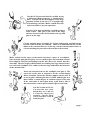
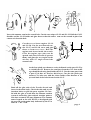
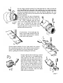
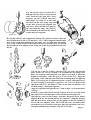
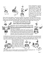
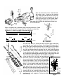
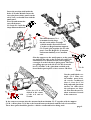
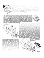
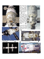
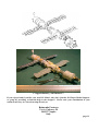
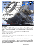
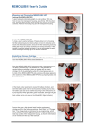
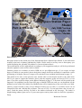
Assembling
User Guide
Part 4: Zvezda
International
Space Station Paper
Model
July 2000 Version
Flights: 1R
Russian Service Module
Model Design: R. Fortezza
Assembling Manual Drawings: G. De Chiara
Dear Modeler,
this paper model is the fourth part of the International Space Station Paper Model. It was built from
scratch on the basis of photos published by NASA. Please notify to me any error or discrepancy you
could find during the assembly. My address is: [email protected]
The modifications will be implemented according to your suggestions and you will be kept informed
when the updated version will be made available.
Detailed pictures are available at NASA WEB site at: speceflight.nasa.gov. If you require an high
degree of fidelity in your model, please check these images before the assembly to control the correct
positioning of each part. However, images of Zvezda have been included in this manual at page 12.
This model is free ware, as the previous ones, and the idea is to develop the model 1:100 of the entire
ISS. If you want to support the initiative please joint the supporter group and send 10 US $, or even
more if you like, to the developer at the address indicated at page 12. Your name will be posted in the
Supporter List published on the Paper-ISS page at MARS WEB site and you can download all the
updated version of the ISS with the new Modules that will be launched up to the end of this year 2000.
Quality printed model (Unity+Zarya+Shuttle Endeavour+Zvezda) is available based on uncompressed files and 1440 dpi ink-jet printer. The cost is US $ 35 or an equivalent value in your currency. Send the money directly via mail to the address indicated at the last page.. The model is
shipped using ordinary post service. If you want express courier please send an e-mail for a quotation
Enjoy
Raimondo Fortezza
Zvezda Assembling Guide
Cut out and bend the parts following the line. For best results use a sharp hobby knife and
a metal straight edge. For some parts small scissor (normal and curved) is better. Glue
together the parts using a thin, even coat of ordinary white glue. Print the sheets on a color
printer. The format of this model should be compatible with both A-4 or US Letter sheet
size. Images of real Zvezda have been included at page 12 to help you during mounting.
The Zvezda Paper model is formed by four printed sheets. Two sheets should be printed on
Glossy paper or a paper sheet of about 100-110 gr/m2. The numbered parts belonging to
these sheet are identified respectively by the letter G1 and G2 followed by the part number.
The third and fourth sheet should be printed on light card board paper (or EPSON Photo
Paper) (about 160 gr/m2) and the parts are identified by the label C1 and C2 followed by
the part number.
Cut the G1-5 and C1-9 part. These parts
are the main body of Zvezda structure.
Glue them together paying attention to the
alignment of the two elements.
If you prefer as alternative you can roll
and glue first the G1-5 using the G1-1 as
gluing tab and then glue the C1-9 on the
tube obtained.
Roll the two parts on a sharp table edge and,
once the shape is similar to a cylinder, glue the
tab G1-1 and form the Zvezda body.
To improve the model accuracy for this part the gluing tabs from the cylindrical parts
has been eliminated and a new separate one the G1-1 has been included to eliminate the
gap formed when a single part is rolled and glued on itself. See the following sketch to
understand the modification.
page 2
Cut the G1-24 part and bend it carefully trying
to follow the shape of the two U shaped structures. This part is the dish support of the large
antenna located in the aft. Use a straight edge
to bend along each line. Make a small cut at the
end of each line to easy the operation.
Cut the G1-14 part and bend it carefully trying to
form a tube. This part is the arm of the large
antenna located in the aft. Bend the end cap and
glue it on the edge.
Cut the antenna motor assembly G1-11 part and bend it carefully trying
to form a tube with the two end lids. There is an additional lid G1-9 to be
added on the external lid to for a flat cap. On the external surface there is
a circle marking the part where the arm has to be located.
Make an hole in the center of the mark and insert a piece of a toothpick.
Once inserted and glued in place cut two small stripes and roll them around
the toothpick. The part protruding from the tube has to be shorter than the
arm tube. The two stripes rolled around are forming two rings located at the
two end of the toothpick. The radius of the two rings shall allow the insertion
of the antenna arm.
Insert the antenna arm on the toothpick and glue it. The
open end of the tube is shaped to fit the round shaped
motor assembly. Insert the antenna support on the arm. If
it stay in place without glue leave it them without glue it so
that it allow a certain degree of rotation respect to the arm.
If the connection is loose than insert a pin from a side so
that the antenna can be pitch rotated respect to the arm.
Cut the Zvezda aft G1-21.
Cut also the two cardboard discs C1-1 and C12. Glue the three part
together. Cut the three
circle marked with R
from the part.
page 3
Insert the antenna arm in the central hole. Cut the two stripes G1-22 and G1-23. Roll the G1-23
Outside and the G1-22 inside and glue them so that the motor arm can be rotated in place but
cannot exit from the hole.
Cut the two re-boost engines G1-19
and G1-20. Cut the two internal nozzles G1-17 and G1-18, curve and glue
them to form two coves. Roll the
engines and insert inside the nozzle.
Close the engine caps (they can be
opened and closed in orbit to protect
them) and glue the two engine in the
aft disc with 15° angle toward the
external side.
15°
15°
Cut the four pitch-yaw thrusters cavity indicated on the part G1-5 by
the circled letter R. Remove the same part from the G1-1 that at this
stage should be already glued inside the G1-5. Cut the same part from
the part C2-6 that are used as thick layer. Cut also the pitch-yaw
thrusters C2-6 (the ones with the 6 dots inside). Glue thruster to the
layer and both to the holes located on the G1-5.
Bend all the glue tabs of the Zvezda aft end and
insert in the main body. Check the tabs and try the
insertion before to glue the parts together. Be careful with the glue to avoid that the antenna rotation
system is stacked by glue residual. Another point to
take into account is the part alignment. The antenna
motor located at the area III has to be aligned with
the area III on the main body indicated by the EVA
mark II <- III -> IIII.
page 4
Cut the large conical section G1-15 and glue the two ends to form the
cut-cone. Bend all the glue tabs. Glue together the two central structure
large disks. Glue the two disks on the shroud using only half of the tabs
(leaving an unglued tab each two). Once the disk are glued to the cone
bend the other tabs and try the insertion in the main body before to glue
the parts together.
Be careful with the parts alignment.
Rotate the conical section so that the
area III indicated by the EVA mark II
<- III -> IIII is aligned with the same
area on the main body indicated in the
same way. As indication the large window on the conical section has to be
aligned opposite respect to the large
antenna located on the aft.
Cut the body G1-10 and glue the
tab to form a tube. Remove the red
circles that represent the rotation
joint of the solar panels.
Cut the striped radiator C1-39, C1-40, and C1-41. remove
the central part from the C1-40. Glue the three radiators
on the G1-10. Roll the G1-10 on a sharp edge. Form a
tube by gluing the tab and attaching the two ends.
Prepare all the tabs of the large conical
section. They have to be bend horizontally respect to the table. Try to fit the
small tube with the main body before to
glue them together. Rotate the tube so
that the two small rectangles (where
the C1-35 parts will be glued) are located on the top of the tube and are
aligned with the area III (it means that
the large aft antenna is located on the
upper part of Zvezda. Glue the small
tube with the main body.
page 5
Cut the small conical section G2-1
and glue the two ends to form the cutcone. Bend all the glue tabs. Glue
together the two central structure
small disks C1-3 and C1-4. Glue the
two disks on the cone using only half
of the tabs (leaving an unglued tab
each two). Once the disk are glued to
the cone bend the other tabs and try
the insertion in the main body before
to glue the parts together.
Be careful with the parts alignment. Rotate the conical section so that the
area III indicated by the EVA mark II <- III -> IIII is aligned with the same
area on the main body indicated in the same way. As indication the empty
area on the conical section located between the two window (grey circles) on
the shroud has to be aligned on the same side of the large antenna located on
the aft.
Cut the C2-1 and C2-4 disks. Cut the G2-27 1st, 2nd, 3th and 4th
parts. There are two set of them. Cut carefully the slot inside each
part; the segment connecting the two halves is located at different
height on each part. Glue the part G-27 1st on the C2-1. Align the
part along a line. Glue the two small tabs orienting them on opposite
sides. Try to keep G2-27 aligned along the vertical. Glue then the G27 2nd rotating of 45 degrees respect to the G-27 1st. Repeat the
operation with G-27 3rd and G-27 4th. At the end you obtain e sort
of "half orange" divided in segments.
Align the segments and glue the two " half orange" to form an entire
"orange ".
Form two cones with G2-30 and G2-31 parts. The G2-30 is the front
part and G2-31 is the back part of Zvezda interconnecting node.
Glue the two cones on the orange structure. Keep the arrow marks
aligned. Roll the G2-10 and glue on the structure. Align the hatches
(the marked circle) with the two circle-segment on the G2-30 and G231 to form two complete circle. The G2-10 has to be oriented so that
the depress valve is located on the port side (the interlock is the foremost part and the large antenna is the aft of Zvezda)..
page 6
These instruction are used to
form two hatches. To build the
second follow the part number
indicated in the brackets. Cut
the G2-12 (G2-17) stripe and
roll it to form a cylinder. The
red side is the internal one.
Glue the G2-14 (G2-26 a)
around the G-2-12 (G2-17) and
glue it. Glue also the G2-15
(G2-26 b) around the G-2-12
(G2-17) and glue it.
Please check if the thickness of this roll correspond to the thickness of the G2-9 disk. If not cut a
part of it or add another piece obtained using the residual part of the sheet. If it is too large
remove a part of the stripe. Wrap the stripe G2-11 (G2-18) around the formed ring. Cut the G2-13
(G2-21) rings and remove the internal part. Glue the ring on the wrapped stripe. Cut the G2-9
(G2-16) connector ring and glue on the ring.
Try to align the teeth of the connector rings
with the dark stripes drawn on the external
surface. Cut the C1-7 (C1-8) hatch and glue
them in place with the two handles aligned along the longitudinal axis. The two air-locks obtained are those located
on the top and bottom part of the interlock and have to be
glued where the arrow indicate the top and Bottom Cross
target on the G2-10 part.
Now form two additional airlock, those used for the automatic mating of Zvezda on Zarya (fore airlock) and the one
used by the progress and Soyuz on the Zveza aft end. Form
a cone with the G2-25 (G2-7) Glue the tabs under the the
Connector ring G2-12 (G2-24. Use the G2-22 as external
surface for the fore airlock and the G2-6 for the aft airlock.
Wrap inside the G2-6 and G2-22 a G2-26 stripe to reinforce the ring. Glue the external ring with
the connector ring. glue the two red caps G2-2 and G2-3 over the two holes of the interlock. Glue
the G2-22 on the fore part (the one with the TV camera docking gluing spot). Keep the G2-6
apart because later is has to to be glued on the aft of Zvezda in the center of the aft end.
Form now the last two hatch
of the interlock. Cot the G2-28
and G 2 - 2 9 r i n g s a n d g l u e
them forming two short tubes.
Fit the two rings on the interlock to find the exact position.
the rounded side has to fit
with the interlock strange
shape.
Once the two rings are in place glued to the interlock, bend all the gluing tabs and
glue on them the port C1-37 and the starboard hatches C1-38.
page 7
Glue the interlock on the small shroud.
Put a thin ring of glue on the shroud
edge and push the interlock inside the
main body. Cut, bend ang glue the G1-16
cable box and gloe on the main body.
Cut and glue the C1-34 over the C1-35.
Glue both pieces inside the hall located in the center of the radiator
Take a 2.5 mm (1/10 “) diameter long wood stick (skewer). Cut it
to have a 115 mm (4.3”) long stick. Use a flat file to reduce the
thickness to 1 mm for a length of 40 mm both sides.
115 mm
2.5 mm
40 mm
40 mm
1.0 mm
For the solar array of Zvezda has been used an approach different from the one used for Zarya. Each Panel is formed by 7
Parts. The parts written in brackets are used for the second panel. Start with the C2-13 (C2-17). Cut it carefully leaving a central slot as indicated in the drawing. Do the same with the photovoltaic side C2-21 (C2-14). Glue the C2-13 on a thick cardboard
1 mm thickness (the shape is not included in the drawings. Cut
the cardboard following the shape and glue on the other side the
C2-21. Remove the central slot also from the cardboard.
Glue the the C2-11 (C2-19) on one side and
stick
the C2-21 (C2-15) on the other. Again remove
tip
the central strip to leave the slot. Cut and glue
the last two stripes C2-22 (C2-16) for the blue
side and the C2-12 (C2-18) for the yellow. Now
there is a slot inside each panel in wich the
wood stick should fit. Cut th two C1-19 parts
and glue them over the two C-20 parts.
Remove the central slot from both disks. Insert
C1-19
the solar panel central tip inside the slot (the Solar
&
orange side is the external side of the disk). Panel
Glue both disks on the solar panel while you attachment C1-20
disks
can leave the stick unglued to allow the model
disassembly.
page 8
Insert the wooden stick inside the
holes of Zvezda Module. Insert the
two solar photovoltaic panels on the
stick. Now you should start with the
small parts.
First cut and mount the
two roll thrusters
G1-2 and G1-3 with the
shape illustrated beside.
The third thruster G1-4
is mounted on the large
shroud on the white rectangle
with the nozzle directed forward.
Cut the two Regul antenna supports
C2-5, bend, glue together the two side
parts. Cuts the Regul G1-12 antenna
and mount similarly to a Canadian
tent.
Glue the support on the small squares on the antennas and glue the tabs on the Zvezda Aft end. Each
antenna has to be mounted in the central gluing
rectangle of each of the three gluing spots. The other
two gluing spot on each side are for the electronic
box C1-39 and C1-40 ( glue them on thick cardboard before put in place to have a more 3D effect.
C1-28
C1-27
Glue the G2-6 aft
airlock in the center
of the Aft end of
Zvezda.
C1-39
C1-40
Cut the small thick rectangle C2-3. Glue over
the similar parts located con the cardboard
sheet 1 close the C1-6
body tube and glue them
on the C1-6 tube where
the red sports are located. Glue also the two fixation structures located
in the same area
In the same area mount also the antenna latch mechanism C1-27 together with its support
C1-28. A Kurs plate C1-26 has to be located between the hatch and the left re-boost motor.
These three parts should be glued to a thicker cardboard before being used.
page 9
Cut and glue on the small conical section the four white disks with
black spots that are target for the automatic docking mechanisms.
On the same section you should mount also the two boxes G2-5 and
G2-4, a short Kurs antenna C1-16 looking forward, the panel 2 C111, the Russian docking target C1-23 looking forward and another
short antenna kurs looking upward. Another Russian target C1-25 is
located starboard and is looking down.
Also the interlock is entirely covered by appendices. Starboard above the
door there is a docking camera G2-19 looking of course forward. Close to it
there is a short Kurs C1-14 antenna looking also forward. Below the door
there is the long Kurs antenna C1-18 looking forward. On the door there is
a dual Kurs antenna C1-13 looking down and on the upper red spot the
large Panel 1 with all the connectors for the future elements. On the port
door there is a Russian docking target looking down and the depressurization valve on the small red spot oriented 45°.
Glue all the parts from C1-30 to C1-33 on a thick
cardboard (1 mm thickness) before use them. Mount
the window cover over the small window located in the
area I of the small body. Cut and roll forming a truncating cone the sun shield G1-6, G1-7 G1-8. The black
side is the internal one. The shields have to be mount
on the gray windows. the large cone has to be mounted
on the back window, while the two small shield have to
be mounted on the two symmetric windows. The three
small cover C1-30 have to be mounted on the already
white window. Glue the three earth horizon sensors
C1-31 on the same shaped squares. C1-32 removable
sensors have to be glued on the same objects. Mount
the Global Time Antenna C1-29 as a box on the same
drawing. Mount the large window cover C2-9 on the
large conical section and
glue over it the opening
Now rotate the model on the EVA Area III.
mechanism C2-1.
Cut and mount the thee star tracker G1-27,
G1-28 and G1-29. Mount the C1-35 in the
central area od the thermal radiator and
glue also the two protective covers of the
panel close to it. Cut, bend and mount the
large docking target C1-22 on the large conical section oriented forward. Mount the
two additional sensors C1-33 on the large
Star
body. Mount also the small connector panel
trackers
C1-12 on the large conical section at 90°
respect to the large Window.
page 10
The Zvezda (area
III) as seen from
Shuttle upperdeck window during ISS docking
phase (note the
docking markers)
The Zvezda area I.
Look at the three
sun shields on the
camera windows,
the large window
cover on the large
conical section and
the thrusters in the
upper part of the
picture
Zvezda aft section.
Note the large
antenna structure
and rotation mechanism.
The entire ISS as seen during
STS-106 flight.
Zvezda during integration
Zvezda area III details
page 11
Congratulation, you finished !!
If you enjoyed and if you like your new ISS Model, why don't joint the ISS Paper Model Supporter group by providing a financial help to the designer? Please send your contribution in your
national currency in a closed envelop directly to:
Raimondo Fortezza
Via A. Falcone, 58
I-80127 Naples
Italy
page 12