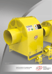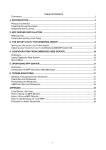
1
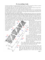
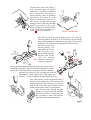
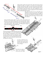
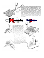
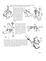
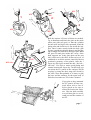
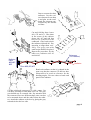
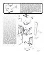
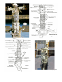
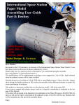
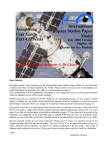
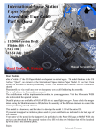
Assembling
User Guide
Part 7: P6
Model Design: R. Fortezza
International
Space Station
Paper Model
November 2000 Version
Flights: 4A
STS - 97
Assembling Manual
Drawings: G. De Chiara
Dear Modeler,
this paper model is a part of the International Space Station Paper Model. It has been built from scratch
on the basis of photos published by NASA. Please notify to me any error or discrepancy you could find
during the assembly. My e-mail is: [email protected]. The modifications will be implemented
according to your suggestions and you will be kept informed when the updated version will be made
available.
Detailed pictures are available at NASA WEB site at: speceflight.nasa.gov. If you require an high degree
of fidelity in your model, please check these images before the assembly to control the correct positioning
of each part. However, drawings of ISS P6 elements have been included in this manual.
These models should be considered as a shareware, as the previous ones, and the idea is to develop the
model 1:100 and 1:144 of the entire ISS. If you want to support the initiative please joint the supporter
group and send a financial support to the developer at the address indicated in the last page. Your name
will be posted in the Supporter list published on the Paper-ISS page at MARS WEB site and you can
download all the updated version of the ISS with the new Modules that will be launched up to the end of
the year 2001.
High-quality printed model (Unity+Zarya+Shuttle Endeavour+Zvezda+Soyuz+Progress+Z1+P6 and
related manuals) is available based on un-compressed files and original sheets printed with 1440 dpi inkjet printer. If you are interested please send me a request via e-mail. I’ll provide you the cost and time
estimation. Send the money directly via mail to the address indicated at the last page. The model is
shipped using ordinary post service. If you want express courier please specify it in your request.
Enjoy
Raimondo Fortezza
P6 Assembling Guide
P6 Element should be mounted in this phase above the Z1. The P6 is formed by 9 Sheets: 4 printed
on glossy paper sheets, 4 cardboard (Photo paper) sheets and 1 transparent.
For your help, make also a b/w copy of each sheet so that you can have the labels, the parts numbers and other indication as reference guide also when the sheets are cut.
In addition to scissor, glue, rulers, cutters and all the common modelers tools, to mount the huge
photovoltaic panels you need two square section stick 7x7 and 6x6 mm to easy the gluing of the
telescopic boom (the material is not important). The length of the sticks should be 25 cm (10“). For
the 1:144 model you need 5 x 5 and 4 x 4 stick.
The P6 will be relocated in the future to form part of the ISS main truss, that in scale 1:100 will be
longer than 1 meter. For this reason the P6 element is really stiff and requires the use of thick cardboard. All the part included in a red dashed rectangles should be glued on this thick cardboard. A
tick cardboard sheet is available in each pack of Epson quality paper and it is suitable as well as
any cardboard with a thickness in the range 0.7-0.8 mm (if you use thicker paper, the elements do
not fit). Cut out and bend the parts following the lines. For best results use a sharp hobby knife and
a metal straight edge. For some parts small scissor (normal and curved) is better. Glue together the
parts using a thin, even coat of ordinary white glue or the new transparent gel glue.
The P6 starts from the four Solar
Print the sheets on a color
#43
Panels mounted in couple. The
printer. The format of this
#43
Photovoltaic (PV) Panels are
model should be compatilong about 35 cm each and canble with both A-4 or US
not enter entirely in an A4 sheet.
Letter sheets size. Images
For this reason each PV has been
of real elements have
#74
cut in several parts. The same
been included in this
approach has been used for the
manual to help
#47
telescopic boom. Print on glossy
you during
#44
#47
paper the sheets PV 2, 3 , 4, and
assembly.
#75
#44
5. The sheets 2 & 3 are the same
sheet so you shall print two copy
of it. The same concept applies
to sheets 4-5 and 7-8.
#46
Cut the parts #44,#48 and #45 representing the solar panels. Print the sheets 7&8
#76
#46
on cardboard (for instance Epson Photo
#48
paper). Cut the #74 and #73 and glue
#73
them on the previous elements. Glue also
#48
the back side of the panel formed by the
parts #43, #47 and #46.
Try to align each part carefully before to glue them.
Leave the glue dry by keeping the part under weight or
inside a large book so that the panel stay flat.
#45 Cut also the central parts #75, #76 and form another solar
panels. At the end you should form 4 different solar panels.
#45
Please note that each panel is not fully symmetric, but an
edge is flat and is the internal one (close to the boom), while
the other is formed by a raw of “teeth” and is the external
one.
page 2
Cut
#77
Cut the other parts from sheets 7
& 8, and glue them on a thick
cardboard. I used the Cardboard
sheet included in each pack of
Epson quality paper as bending
protection. It is about 0.7 mm
thick. Cut all the parts from #77 to
#91. Please consider that in this
block part #89 is the only one that
shall not be glued on the cardboard. All the part indicated with
a red capital R surrounded by a
circle R has to be removed.
Glue on Cardboard
Glue back to back the panel supports parts #77 and #78.
The two squared areas have to be removed. Cut also all the
four small rectangles as indicated in the figure. Do the same
with parts #79 and #80. Keep aligned the two parts and
the four small slots
during gluing. Cut
and glue the three
#87 squares as a
#86
stack. On the top glue
the part #86. At the
end you should
#87
#78 mount two different
couples of supports.
Now you should start to mount the telescopic boom used to
#79
extend the solar panel. The boom shall be printed on a transparent sheet. The first boom is formed by the three different
parts #92, #93 and #94. The second boom with #95,
#80
#96 and #97. I used a plastic stick with square section of 7 x 7 mm as support during the gluing phase.
Use a sharp knife on the not-printed side to
engrave the bending lines. The external side
is the printed one. The glue has to be distributed on the clear side and distributed uniformly on the entire side. Use transparent
glue for the boom. During the glue
drying use clips to keep the surfaces
pressed each other. Using the stick
this operation is more easy and the
glue form a thin transparent layer.
page 3
Boom 1
#92
#96
#95
Glue first the section #92. Do the same with section #94. The two
elements in reality are formed by very thin steel and carbon fiber
structure. Since for the model we need a stiff structure the transparent sheet has been selected as the more realistic approach. Try to
glue carefully so that the structure stay more transparent as possible. Use the second stick 6 x 6 mm to glue part #93. Once the three
#93
parts are dried glue them together.
The part red of #92 is one tip. The other tip is
indicated on the side of part #94. The element
#93 has to be glued inside and in the middle of
#94
the boom. Pay attention to distribute the glue
uniformly on the #93 before to insert it in the
#92 and #94.
#97
Boom 2
Once the boom is dry, insert it in the #79-80. The tip has to be
inserted in the stacked squares. Take also two solar panels. Put the
blue side of the panel as indicated in the drawing below and the
“teeth” edge external. The four stripes have to be inserted in the four
slots of the supports. Once in place, you shall glue the stripes on
both side of the support and let them dry.
teeth
Yellow side
teeth
Blue side
Once the elements are dried insert the boom also
on the other support #77-78. The red part has to
pass through the squared hole of the support.
The four stripes of the PV panel have to be
inserted in the four slots of the supports and the
two panels have to be kept tight between the two
supports. Use a pair of tweets to pull the strips
and align the solar panel.
Cut the cardboard reinforced parts #81, #82, #83
and #84. Insert them in the
boom tip and glue them on
each red stripe.
Read the next page to
check the distance
between the four disks.
page 4
For a better realism I designed also the rotating mechanism for the beta joint, so that the panels can be oriented toward the sun. You need a wooden stick with a
diameter of 3 mm and a length of 4.5 mm (for the
1:144 model use a 2 mm one for a length of 3.2 mm).
Cut the four reinforced squared parts #88. Cut an hole
in the center of each part and insert each of them in the
stick. The distance of the disks and of the squares in
indicated in the drawings. Before glue disks and
squares check how they fit on the boom and adjust
accordingly.
5
10
5
16
Boom
Disks
Stick
5
14
10
45 mm
Squares
Cut, fold and glue the four
panel containers #49, #50,#51
and #52. You need two set of
them. The container has two
open areas in the base to
allow the stripes of the solar
panel protruding from the
support to stay inside the box.
Glue a couple of containers
on each panel support. The
two photovoltaic panels are
ready!!
Cut the supports of the boom
canister #90 from sheets 7 & 8.
Glue them on the cardboard and
let them dry flat under a weight.
Cut carefully with a cutter from
the cardboard including the long
horizontal slots located on both
side in the middle.
page 5
Prepare the boom canister support #90. It has been reinforced with
cardboard. Cut and bend has indicated in the drawing.
1
Remove the circle from
the support. Flip first the
left and right part to the
internal side. Do the same
with the lower part; then
the lower part has to be
bent and inserted inside.
Follow the drawing for a
better understanding. Be
aware that this part has to
be very stiff because it
has to sustain the entire
weight of the Photovoltaic Panel
2
3
Cut also the part #89 and
#91 reinforced. Insert the
#91 inside the #89 as
depicted in the left drawing.
Flip the three rectangles
around the circle forward;
flip the other walls backward. Be aware that, once
the glue is dry, you have to
remove a 3 mm diameter
disk in the center.
Glue together the part #89 and #90 by inserting the #89 inside
the #90. This part is not very realistic simply because the real
canister does not support the weight of the solar panel (the
gravity force on the ISS is less than 1 millionth respect to earth
- this environment is called microgravity). However the shape
of this part is not so bad and I hope that also the purists can
accept it (it is also slightly larger than reality).
page 6
#58
#59
1
#90
2
3
#59
#89
#40
#40 side
Roll the canister #59 (two of them are needed).
Try to distribute uniformly the glue on the entire
white part with red spots, so that the cylinder
become stiff and rigid. Once mounted, bend the
gluing tabs and check how it fits inside the support. Once it enter exactly inside the hole, glue
in place considering that the harness and the gluing rectangle are located on the upper part. Bend
the part #58 and glue inside the cavity. Once
both supports are ready glue them on the part
#40 reinforced with three different layers of
cardboard to avoid the torsion caused by the not
symmetric geometry of the panels. Once the 3
layers are dried, glue around the #40, the belt “
#40 side”. Use clips to ensure good gluing and
contact between the layers dry. At this stage you
can insert the PV panels in the canisters and fit
on place by using the three rings #85 closed by
the #85b. Note that probably it is better to glue
the base and the canisters on the main body of
P6 before insert the two PVs in the Canisters.
If you plan to keep mounted
the PV panels all time suspend them with a line of
nylon glued at the tips to
reduce the load on the canisters. Glue the disk carefully
to avoid that glue in excess
could prevent the rotation of
the PV.
page 7
Start to mount the three
radiators. Cut the various elements from sheet
6 and glue on the cardboard the elements surrounded by the dashed
red lines.
Cut and fold the three boxes
#69, #70 and #71. Glue them
in the center of the radiator
plates #66, #67 and #68 that
need to be reinforced with
cardboard. Glue back to back
the radiators #60 and #61. Pay
attention to align them carefully. The gray part with
small strips shall not be glued.
Repeat the procedure for the
other two radiators #62-63
and #64-65
Radiator
Plate
#66,#67,
#68
Extensors
(2 x Radiator)
Radiator
Box #69,#70,#71
Bend each radiator so that it is shaped in the
same way that the extensor #72 that are here
illustrated to be used as reference for the
bending angles. Use two rulers to bend each
panel of the radiator.
Cut the reinforced extensors #72 with a cutter. Cut
carefully avoiding to bend them once cut. The gray
part should stay as external side. Pay attention that
the extensors have two different shape since one has
to be mounted above and the other below the radiator. Attach the radiator to the box by gluing the gray
tab and stick to the box side.
page 8
Once mounted each
radiator has to be
shaped like the drawing on the right. You
need to mount three of
them to be attached to
the P6.
Fold and mount the
box #14. Glue it on
the plate #12 reinforced with cardboard.
Fold and mount
the support #35
and #36. Glue on
the tip the half circle #31 and a small
steel wire in the
center.
Fold and mount
the support #56
formed by gluing back to back
the reinforced
parts #56 and the
surrounding belt
# 5 3 . D o t h e Roll and glue
same with parts the tube #55 (three of them are
#57.
needed, one is spare). Each
tube has to be cut for the needed length.
Fold and mount the keel
support #23 and #24 and
the internal and the surrounding belts #26 and
#25. Glue on the tip a
small piece of steel wire
in the center.
Support #56
Tube #55
#32
Glue the tube to the supports
and cut of the right length.
Glue on the tip the half disk
#32 and a small piece of steel
wire. Repeat the procedure for
#57.
Fold and mount the
keel support #21,
#22 and the surrounding belt #27.
Glue on the tip a
small piece of steel
wire in the center.
page 9
Picture of the P6 during integration at Kennedy Space Flight Center. The P6 is formed by the Long
Spacer (left part) and the Integrated Equipment Assembly - IEA right part. The side shown is the forward. please note the position of all the target to be placed on the model. If you want to improve the
realism note the sort of pocket located in the central part of the covering blanket. The support you can
see is the #56 and you can understand how to mount the tube #55. In the lower side of the structure
are located the two keel fixations #22 and #23 with the protruding steel rod .
Picture of the P6 in the integration hall at KSC suspended over the MPLM. The side shown is the
aft. Please note the position of all the target to be placed on the model. The support you can see is
the #57 and you can understand how to mount the tube #55 and the grabble fixture for the Shuttle
Remote Manipulator System. In the lower side of the structure you can see the keel fixation #22
with the steel rod protruding and the two target (note that one is mounted at 90° respect the other.
Mount the movable grabble fixture
formed by part #39 to be fold and
glued and #41 simply reinforced with
cardboard. Over it can mount on it the
last grabble fixture #38 installed there
during a recent flight
page 10
As final step we need to build the main body of P6
formed by IEA and the Long Spacer. We start from the
base #8 reinforced with cardboard on which, to improve
the stiffness, you should glue the four triangular supports
#42. Please consider that the printed part is the external
one and that the triangles should be mount on the other
side. Do the same with the other plate #9, #10 and #11.
As already explained the P6 has been designed to be very
stiff to sustain the bending load once it form the ISS
structure long more than 1 meter.
Note that the forward and aft panels are formed by two separate
parts, while port and starboard is
formed by a continuous panel.
All the panels and the bases need
to be reinforced with cardboard.
Glue them under a weight to keep
them perfectly flat. On the starboard and port panels there are two
slot needed to fix the #9 and #10
bases. To improve the realism try
to cut the slot only on the cardboard and not on the colored external sheet. Make a test with all the
part in the right place without glue
to check how they fit. Please consider that each base has different
joints for each panel so that its correct position is unique. Additional
drawing have been add at the end
of this manual to check the position of small parts. Once glued try
to use clips, rubber bend or other
systems to leave all the element in
place during the glue drying. The
part #13 and #7 are not reinforced,
but has to be glued on the upper
and lower base at the end of this
assembly. These elements will not
be visible, since the base will be
glued to Z1 and #13 will be covered by #40, however they have
been included bur a great realism.
#13
#11
#3
#6
#4
#10
#1
#9
#5
#2
#8
#7
page 11
Now, the final effort !!
Glue the PV boom canister
base over the P6 main body.
Glue all the three radiators in
place. Attach also the large
box #12-14, the small box #15
over its base #16 (reinforced)
and the two boxes #17 and
#18. The Boxes #28, #29 and
#30 have to be mounted close
to each radiator in their specific gluing boxes. Mount also all
the target and the the grabble
fixtures on the modules.
The supports #35 and #57 are
mounted on the Forward panel. The support #36 and #56
on the Aft panel.
At the end you should have
only few unused parts: #53,
#54, #55, #56 and #57 that are
spare !
Now you can glue the entire
P6 over the Z1, where it will
stay until it will be relocated
to form the ISS main truss.
Congratulation, you finished your P6 element !!
If you enjoyed and if you like your new updated ISS Paper Model, why don't joint the ISS Paper Model
Supporter group by providing a small financial help to the designer?
Consider that I spent more than 100 hours only to design the P6, to test it and to write this manual !!
For further info read the web page: http://www.marscenter.it/iss/paper_iss_model.html
Please send your financial contribution in your national currency in a closed envelop directly to:
Raimondo Fortezza
Via A. Falcone, 58
I-80127 Naples
Italy
Thanks !!
page 12
page 13
page 14