1
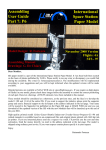
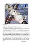
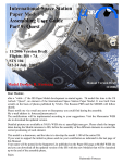
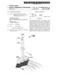
International Space Station
Paper Model
Assembling User Guide
Part 8: Destiny
12/2003 Version
Flights: ISS - 5A
STS 98
7-20 Feb. 2001
Model Design: R. Fortezza
Assembly Drawings: G. De Chiara
Manual Version 1.1
12/2003
Dear Modeler,
this model is the US Laboratory, an element of the International Space Station Paper Model. It was
built from scratch on the basis of photos published by NASA.
Please notify me via e-mail any error or discrepancy you could find during the assembly.
My e-mail address is: [email protected]
The modifications will be implemented according to your suggestions. You will be kept informed
when the updated version will be made available.
Detailed pictures are available at NASA WEB site at: spaceflight.nasa.gov. Please check the images
taken during the Shuttle missions to ISS, before the assembly of the different elements to control the
correct positioning of each part.
This model is a shareware, and the idea is to develop the model 1:100 of the entire ISS.
If you want to support the initiative please send me a financial contribution as indicated in the last
page of this Manual.
Your name will be posted in the Supporter List published on the Paper-ISS page at MARS WEB site
and you will get the right to download all the updated version of the ISS with the new Modules that
will be launched up to the end of the assembly phase.
Enjoy
Raimondo Fortezza
US Lab "Destiny" Assembling Guide
Cut out and bend the parts following the line. For best results use a sharp hobby knife and a metal
straight edge. For some parts a pair of small scissors is better. Glue together the parts using a thin, even
coat of ordinary white glue. Print the sheets on a color printer. The format should be compatible with
both A-4 or US Letter sheet size. I used an EPSON 750 Color ink-Jet Printer with a resolution of 1440
dpi with excellent results.
Destiny parts are printed on a single sheet. It should be printed on glossy paper (available for any ink-jet
printer). The numbered parts belonging to this sheet are identified by a number. The parts included in
dotted red lines should be reinforced by gluing them on a cardboard sheet before the cut. The part
- indi
cated with red red oblique hatch should be removed. The part indicated as transparent should be cut
using a transparent sheet (the one used for the overhead projector is good).
Cut the part 1 and the gluing tab 2 carefully. Put the glue on the tab only on one side and glue it to
the main body of Destiny part 1. Take note the of the colored triangles (violet and green) to be
used later on for the alignment of the terminal cones (I suggest to . .
WARNING:
If you want to insert the optional transparent window, located on Destiny zenit position used for
earth observation, pleas follow the instruction contained at page 3, otherwise you can continue with
the following instruction.
Roll the part 1 on a table edge and, once
the shape is similar to a cylinder, glue the
second half of the tab and form the Destiny body.
Pay attention to the gluing phase. Align the sheet
edges on the tab trying to eliminate any gap between
the two parts. Use a small tube inside the destiny
body to press the part during the drying period. Use
small amount of glue to avoid that it spread out on the
external side of the model.
page 2
Transparent window mounting (optional)
Cut and remove from the main body the disc of the
window.
Cut and remove from the reinforced part 16 the disc
located in the central part.
OPTIONAL
The instructions contained in this page are optional. This page can be skipped to simplify the
model. The window is already painted on the model but is not realistic as the transparent one.
Use the element 17 as shape to cut a small part of a
transparent film The transparent film for overhead
projector fits well. Pay attention to use a small
amount of glue to avoid to spot the transparent part.
Cut and remove from the reinforced ring 18 the disc
located in the central part.
Glue the reinforced ring outside the window
and the element 17 with the transparent foil
internally. Keep aligned the elements to form
the transparent round window on the body.
OPTIONAL
page 3
Cut the reinforcing disk 3 carefully with all the
gluing tabs. Glue the disk 4 on cardboard and cut
it. Glue the disk 3 over the disk 4 and bend at 90°
the tabs alternately forward and backward. as indi
cated in the drawings.
Part 3
Part 4 reinforced with cardboard
When the glue of the tube is dried
insert the reinforcing disk up to the
about the middle of the cylinder. Pay
attention to the window and try to
avoid to overlap the tab to the
- win
dow.
Before to put the glue in the tube or on the tabs, check if
the disk 3 enter freely in the tube and do not deform it. If
it is too tight then reduce its dimension. Try to keep the
tube cylindrical and to avoid to deform it with the disk 3.
Cut and glue one of the end cone (part 5). The
gluing tab is separated. Pass the element on a
sharp edge of a table several time so that the
element assumes the conical shape naturally.
Warning: keep note of the position of the small
green triangle located on the external side of the
part to be used for the alignment of the end
cone with respect to the main body (I suggest to
write a small mark on the back side of the part).
Cut the elements of the mating ring 5 and 6
and glue them back to back. Leave unglued the
opposite part of the tab, so that it can be glued
later between the two layers. Roll the element
on a sharp edge of a table several time so that
the element assumes the round shape naturally.
At this stage glue the tab inside the two layer.
page 4
Insert the mating ring 5 and 6 inside the end
cone. There is not any precise alignment for
this element.
Bend the gluing tabs inside the end cone and glue them
inside the end cone.
Cut the element 8. It is a multilayer blanket used as
thermal protection of the access hatch. -Glue the rein
force disk 9 and glue the two disks 8 and 9 together as
indicated in the picture on the left.
Bend the gluing tabs at 90° and insert the protection
panel inside the mating ring. This is the launch and
transport configuration to the ISS.
Be aware that the panel has to be aligned to the end
cone. The vertical bands of the panel should
corre
spond to the direction up-down or Nadir-Zenit of the
Destiny module. The window correspond to the Nadir
position and, being oriented toward the earth it is used
for earth observation.
The end cone should be oriented aligning the
- two tri
angles green reported on the sheet. Of course the same
is valid for the two triangles violet used for the other
end cone.
WARNING!!: If you want to realize the version attached to the Space Station, once the Destiny
model is completed, you should cut off the protruding small teeth used for the self alignment of
the elements during the mating. Remove the PMAs from the Front and Nadir hatches of Unity
(cut them carefully and, if needed, build new PMA). Glue this hatch to the front hatch of Unity.
Refer to the picture for the orientation of the Modules. Glue one of the PMA to the port hatch (the
one close to the "Unity" Label). The Nadir port of Unity is used to mate the MPLM and do not
need the PMA for this function. The other PMA will be used later (page 7).
page 5
Cut and glue one of the end cone (the part 10).
The gluing tab is separated. Pass the part on a
sharp edge of a table several time so that
- the ele
ment assumes the conical shape naturally.
Warning!!: keep note of the position of the small
green triangle located on the external side of the
part to be used for the alignment of the end cone
with respect to the main body.
Cut the elements of the mating ring 11 and 12
and glue them back to back. Leave unglued the
opposite part of the tab so that it can be glued
later between the two layers. Roll the element
on a sharp edge of a table several time so that
the element assumes the round shape naturally.
At this stage glue the tab inside the two layer.
Insert the mating ring
11 and 12 inside the
end cone. There is
not any precise align
m e n t f o r t h i s e l ement.
Bend the gluing tabs
inside the end cone
and glue them inside
the end cone.
Cut the element 13. It is a multilayer
blanket used as thermal protection of
the access hatch. Glue the reinforce
disk 14 and glue the two disks 13 and
14 together as indicated in the picture
on the left.
page 6
Bend the gluing tabs at 90° and insert the protection panel inside
the mating ring. This is the launch and transport configuration to
the ISS. .
Be aware that the panel has to be aligned to the end cone. The
vertical bands of the panel should correspond to the direction updown or Nadir-Zenit of the Destiny module. The window
- corre
spond to the Nadir position and, being oriented toward the earth,
it is used for earth observation.
The end cone should be oriented aligning the two triangles green
reported on the sheet. Of course the same is valid for the two- tri
angles violet used for the other end cone.
WARNING!!: If you want to realize the version attached to the Space Station, once the Destiny
Model is completed, you should cut the disk 33 and glue on the element 13 aligning the octagonal
shape. Remove the PMA from the front hatch of Unity (cut it carefully and if needed build a new
PMA). Glue this PMA to the panel 33. This is the PMA where the Shuttle mate the ISS during the
servicing.
Insert each of the two
disk inside the end
cones. Bend the gluing
tabs alternately to fit
the disk inside the end
cones.
Now you need two disk 15.
Glue both of them on card
board to reinforce them. .
Glue the tabs as indicated on the left drawing.
Remember that the two end cones need to be aligned to
the Destiny module according to the colored reference
triangles.
At this stage it is possible to glue
the end cones. Pay attention to
avoid to invert the end cones and
to align them carefully before to
glue them to the Destiny main
body Check the position before
putting the glue.
Align
Align
page 7
To increase the fidelity and the realism some more detailed elements have been prepared. The
same elements are however already painted on the Destiny body so that this part has
- to be con
sidered optional.
Glue the elements 22 and 25 on a card board
and cut them. Insert them inside the structure
21 and 23 used to fix the Destiny module
inside the Shuttle cargo bay. Bend slightly
the two triangular panels. Check the picture to
understand how the real elements are formed .
Insert the elements 24 reinforced with cardboard
below the elements 24 that are the other two locking
mechanisms used to fit the Destiny module inside
the Shuttle cargo bay
Glue the four locking points in the same
position drawn on the module.
To increase the realism it is possible to
include four small pieces of steel wire
(needle, staples), which should protrude
from the elements of about 1.5 mm. or
0.06" as illustrated in the left picture.
OPTIONAL
page 8
OPTIONAL
Details - Optional part
OPTIONAL
Details - Optional part
Glue the part 27 on cardboard to increase the thickness. Remove the part
with red stripes.
Cut the element 26 and glue it on the- card
board 27 forming a small box.
Bend the gluing tabs under the element
Check the picture to understand how the
real elements are formed
Cut the disk 28 after it has been glued- on card
board. Glue the elements 26 and 28 on the- posi
tion illustrated on the main body of Destiny.
To increase the realism it is possible to
remove the central part of disk 28 to form
a ring, but it is difficult due to the very
small dimensions of the element.
OPTIONAL
page 9
Glue the two disks 19 back to back. they represent
the shield to protect the window from the Space
debris.
Glue the stripe 30, bend at half, and glue the two
halves parts. Once dried, bend in the middle and glue
it to the shield.
Glue the shield close to the window as indicated on the right. .
Cut a small part of steel wire (5 mm or 0.2".) Cut the
elements 29 of the keel and glue them on the cardboard.
Glue them together back to back inserting the
- protrud
ing wire between them. Wrap the stripe 30 around the
keel, before gluing it to the Destiny Body in Zenit posi
tion.
Glue the grasping disk on
the cardboard and glue it
on the small gray circle
located close the line of
conjunction of the Destiny
body.
Now if you want you can
attach Destiny to the ISS
model!
Congratulation, you finished your Destiny Module !!
If you enjoyed and if you like your new ISS Model, why don't you joint the
ISS Paper Model Supporter group by providing a financial help to the
designer?
Please send your contribution using PayPal or sending it directly in your
national currency in a closed envelop directly to:
Raimondo Fortezza
Via A. Falcone, 58
I-80127 Naples
Italy
page 10