1
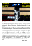
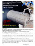
Assembling User Guide
Part 9: Quest
11/2006 Version Draft
Flights: ISS - 7A
STS 104
12-24 July. 2001
Model Design: R. Fortezza
Manual Version Draft
11/2006
Dear Modeler,
after a “while :-)“ the ISS Paper Model development re-started again. Th model this time is the US
Airlock “Quest“, an element of the International Space Station Paper Model. It was built from
scratch on the basis of photos published by NASA. The Russian PIRS and the SSRMS will follow
shortly
Please notify me via e-mail any error or discrepancy you could find during the assembly.
My e-mail address is: [email protected]
The modifications will be implemented according to your suggestions. Visit the Marscenter WEB
site to download the updated version.
Detailed pictures are available at NASA WEB site at: spaceflight.nasa.gov. Please check the images
taken during the Shuttle missions to ISS, before the assembly of the different elements to control the
correct positioning of each element.
This model is a shareware, and the idea is to develop the model 1:100 of the entire ISS.
If you want to support the initiative please send me your contribution as indicated in the last page of
this Manual.
Your name will be posted in the Supporter List published on the Paper-ISS page at MARS WEB site
and you can download all the updated version of the ISS with the new Modules that will be launched
up to the end of the assembly phase.
Enjoy
Raimondo Fortezza
US Airlock "QUEST" Assembling Guide
Cut out and bend the parts following the line. For best results use a sharp hobby knife and a metal
straight edge. For some parts a pair of small scissors is better. Glue together the parts using a thin, even
coat of ordinary white glue. Print the sheets on a color printer. The format should be compatible with
both A-4 or US Letter sheet size. I used an EPSON RS600 Color ink-Jet Printer with EPSON Glossy
(light paper) or Photo (cartboard) and a resolution of 1440 dpi with excellent results.
QUEST parts are printed on a single sheet. It should be printed on glossy paper (available for any inkjet printer). The numbered parts belonging to this sheet are identified by a number. The parts included
in dotted red lines should be reinforced by gluing them on a cardboard sheet before the cut. The part
indicated with red red oblique hatch should be removed. The part indicated as transparent should be cut
using a transparent sheet (the one used for the overhead projector is good).
Cut the part 1 and the gluing tab 2 carefully. Put the glue on the tab only on one side and glue it to
the main body of Destiny part 1. Take note the of the colored triangles (red and green) to be used
later on for the alignment of the terminal cones (I suggest to mark with a pen the inner part of the
element to identify the zenit (Red) or nadir (Green) point of the module)
Roll the part 1 on a table edge and, once
the shape is similar to a cylinder, glue
the second half of the tab and form the
QUEST body.
Pay attention to the gluing phase. Align the sheet
edges on the tab trying to eliminate any gap between
the two parts. Use a small tube inside the destiny
body to press the part during the drying period. Use
small amount of glue to avoid that it spread out on the
external side of the model.
page 2
Part 3
Cut the reinforcing disk 3 carefully with all the
gluing tabs. Glue the disk 4 on cardboard and cut
it. Glue the disk 3 over the disk 4 and bend at 90°
the tabs alternately forward and backward. as indi
cated in the drawings.
Zenit (UP)
Part 4 reinforced with cardboard
Cut and glue one of the end cone (part 3). The gluing
tab is separated. Pass the element on a sharp edge of a
table several time so that the element assumes the
conical shape naturally. Warning: keep note of the
position of the small green and red triangles located
on the external side of the part to be used for the
alignment of the end cone with respect to the main
body (I suggest to write a small mark on the back side
of the part). Green Triangle is Nadir (down) position,
while Red Triangle is Zenit (up) direction
AB
AB
Nadir (DOWN)
Glue the reinforce ring 4 on a cartboard.
Once it is dry ut the reinforce ring and
remuve the internal part to form a ring
Cut the elements of the mating ring 5 and 6 and glue them back to back. Leave unglued the opposite
part of the tab, so that it can be glued later between the two layers. Roll the element on a sharp edge of
a table several time so that the element assumes the round shape naturally. At this stage glue the tab
inside the two layer. Slip the ring in the mating ring and glue in position
page 3
Insert the mating ring 5 and 6 inside the end
cone. There is not any precise alignment for
this element.
Bend the gluing tabs
inside the end cone
and glue them inside
the end cone.
7a
7b
Leave the gluing tabs flat and insert the hatch from the
back of the cone. .
Cut the port 7. You have two option: the
launch configuration with a thermal
blan
ket fixed to the door (element 7b). It is a
multilayer blanket used as thermal protec
tion of the access hatch. Or, option 2, the
real door, how it appears once the blanket
is removed (element 7a) .
Check the alignment!!
Be aware that the hatch has to be aligned to the end
cone. The vertical bands of the panel should
corre
spond to the direction up-down or Nadir-Zenit of the
QUEST module.
The end cone should be oriented aligning the
- two tri
angles green reported on the sheet. Of course the same
is valid for the two triangles violet used for the other
end cone.
WARNING!!:
If you want to realize the version attached to the Space Station, once the QUEST model
is com
pleted, you should cut out the protruding small teeth used for the self alignment of the elements
during the mating. Glue this hatch to the starboard hatch of Unity. Refer to the picture for the
- ori
entation of the Modules. Glue one of the PMA to the port hatch (the one close to the "Unity"
Label). The Nadir port of Unity is used to mate the MPLM and do not need the PMA for this
function. The other PMA is attached to the front port of Destiny .
page 4
Now you need the disk 8.
Glue it on cardboard to
- rein
force them. .
Insert the disk inside
the end cones. Bend
the gluing tabs alter
nately to fit the disk
inside the end cones.
Glue the tabs as indicated on the left drawing.
Remember that both end cones need to be aligned to the
QUEST module according to the colored reference -trian
gles.
Align it rotating it until both Zenit
marks are aligned
At this stage it is possible to glue the first
end cones. Pay attention to avoid to invert
the end cones and to align them carefully
before to glue them to the Destiny main
body Check the position before putting
the glue.
Align
Roll the part 9 on a table edge and, once
the shape is similar to a cylinder, glue the
two tabs 9a and 9b first on one end.
When the glue is dried then glue the
other end of the cylinder and form the
QUEST exit compartment.
Pay attention to the gluing phase. Align the sheet edges on the tab trying to eliminate any gap between
the two parts. Use a small tube inside the QUEST exit compartment body to press the part during the drying period. Use small amount of glue to avoid that it spread out on the external side of the model.
page 5
Bend the gluing tabs at 90° and cut the exit hatch
- cir
cle from the cylinder
Roll the exit hatch part 10 and glue it forming a ring.
The ring has to have a slight conical shape
Glue the exit hatch on the exit -compart
ment cylinder
Cut the end panel 11 of the exit -compart
ment Bend at 90° the gluing tabs of the
end close to the exit and glue on it the end
panel. Please be aware that the end panel
must be aligned
Align the panel before gluing
Align the shroug before gluing
Glue the exit hatch thermal blanket 12, the handrail 13 and the shroud 14. Roll
the shroud and form a cone. Glue the hatch thermal blanket and the hand rail on
the EVA hatch. align the Gluing Tabs at the end of the cylinder, insert the
shroud and glue them inside the shroud as illustated in the right drawing. bend
the gluing tabs of the shroud flat.
page 6
Cut and glue one of the end cone (the part 15). The
gluing tab is separated. Pass the part on a sharp
edge of a table several time so that the element
assumes the conical shape naturally. Warning!!:
keep note of the position of the small green
- trian
gle located on the external side of the part to be
used for the alignment of the end cone with respect
to the main body.
Cut the discs no. 16 and 17.
The disc 17 shall be glued
or printed on cartboard..
Glue the disc 16 on the back of the cone 15 as
illustrated on the right drawing. There isn’t any
alignment to maintain this time.
Check the alignment!!
Now you are ready to
assemble the starboard
side of QUEST. Glue
the disc 17 on the end
cone 15 keeping the
disc exactly in the
- cen
ter. Check that all the
gluing tabs of the exit
cylinder are flip flat and
glue the exit cylinder on
the end cone. Keep the
parts pressed until the
glue is dried.
Align the Cone and the cylinder
before gluing them together
page 7
Now you need the disc 18. Glue it on cardboard to reinforce it.
Insert the disc 18 inside the end cone. Bend the
gluing tabs alternately to fit the disk inside the
end cones.
Glue the tabs as indicated on the left drawing.
Remember that the two end cones need to be aligned to
the Destiny module according to the colored reference
triangles.
Check the alignment!!
Align
Align
At this stage it is possible to glue
the second end cone (starboard
side). Pay attention to align it
carefully before to glue it to the
QUEST main body Check the
position before putting the glue.
Cut the OCEANEERING Toolkits
Tray (element 19). Bent it and
glue it to form a Flat Tray to glue
on the front (left) side of the Exit
Cylinder. The try is used to fix the
two toolkits 20 and 22. The orien
tation is indicated by the -two dif
ferent colored dots.
page 8
Now there are two very difficult elements, due to
their very small dimension. They are the two
toolkits manufactured by OCEANEERING, a sim
ple wall box with two doors. You can decide to
built them in two different way, one more difficult
than the other. Lets start from the more difficult.
Cut the Elements 20 and 22. Flip the two small
simmetrical frames and glue them so that the
drawing stay outside. They are the doors
- contain
ing tools. Then close the main box body leaving
the small triangular parts external. Cut the very
tiny elements 21 and 23, bend as indicated on the
instruction and glue them under the triangle. In
this way you can open the toolbox to show the
tools!! You need some repositioning glue (like the
one of the post it to leave the doors closed) and to
open them when you want. The problem is that
each door has a dimension of 4 x 6 mm!!
If you decided to- fol
low the easiest way,
cut the extreme frames
and throw them in the
waste basket. Cut the
more internal ones
(those where the -stick
er Toolbox is located
and glue them directly
on the Box. It is easy
but you cannot open
the box anymore.
Eliminate them.
If you succeded to built the two toolboxes then
you are almost at the end of the construction (be
proud of yourself!!) Using the color code you
cannot glue the toolboxes in the wrong position
or direction. Consider that the arrow starboard
indicate that this side has to be oriented toward
the end of the exit cylinder.
page 9
Now is the time to build the four O2 and N2 Can
isters. The elements are indicated from 24 to 27 in
the QUEST Sheet No2. Cut each of them and glue
to form a “house” shaped volume. The bottom
part is curved to adapt the shape to the QUEST
main body where they are attached,
On each of them glue the small label indicated respectively
with the number from 24a to 27a; (even though they are too
small to read them, you need a 10000 dpi to print readable);
they indicate the different name of each canisters. If you
like as option you can glue also the grapple fixture used to
grab each canister with the ISS robotic arm. All the grabble
fixture are indicated as parts 33 and should be glued on the
grabble fixture already painted on the canister
Now the last effort. Glue the four canisters at their
respective positions. Check the mark close to the Main
Body part No 1, as well as the drawing illustrated below
on the left side illustrating the QUEST from
the star
board direction. Please be sure to position the module in
the right orientation. The exit hatch is oriented in the
Nadir (down ) direction, Attach also the tool boxes tray
on the exit cylinder. Check also the picture in the next
pages to understand better the position of each element.
page 10
Details - Optional part
To increase the fidelity and the realism some more detailed elements have been prepared. The
same elements are however already painted on the QUEST body so that this part has- to be con
sidered optional.
Glue the elements 30 and 31 of QUEST
Sheet 2 on a card board and cut them. They
are used to fix the QUEST module inside
the Shuttle cargo bay. Check the picture to
understand how the real elements are
attached. Glue also the grabble fixture
No.32 on cardboard and then on- the grab
ble fixture already painted on the main
body of the QUEST Module..
Cut and glue the NASA logo 34 of QUEST
sheet 1 that is painted on a separate
alumi
num panel on the QUEST main body.
Glue the two locking block
in the same position drawn
on the QUEST module.
To increase the realism it is
possible to include four
small pieces of steel wire
(needle, staples), which
should protrude from the
elements of about 1.5 mm.
or 0.06" as illustrated in
the above picture.
page 11
OPTIONAL
Details - Optional part
MISSE 28a
Grabble Fixture Thermal Blanket
Truncheon Thermal Blanket
MISSE 28b
As you can see on the above picture in the orbital configuration all the exposed elements as Grabble
Fixture and Truncheons are covered by thermal blankets. For this reason I prepared the element 35
to cover the Body gabble Fixture, and the 36 and 37 to cover the truncheons (the Space Shuttle -fixa
tion rods). However the glossy paper is too stiff and I don’t know if the final look seems realistic.
May be that small pieces of very thin paper tissue appears more realistic. If you like you can then
replace the pieces 35, 36 and 37 with similar element made in paper tissue.
Now the two MISSE experiments (Material on
ISS Experiment) Elements No. 28a and 28b of the
QUEST Sheet 1 to be folded on themselves and
glued in the positions illustrated in the above
- pic
ture
OPTIONAL
page 12
OPTIONAL
As you can see from the above pictures there is
a difference from the Canister from the launch
to the orbital position. Even there a small
- ther
mal blanket as been added on the grabble
fix
ture point. Four thermal blanket elements are
the elements 38 of the QUEST Sheet 2.
1
2
Cut a small part of steel wire (5 mm or 0.2".) Cut the elements 28 of the keel and glue them
on the cardboard. Glue them together back to back inserting the protruding wire between
them. Wrap the stripe 29 around the keel, before gluing it to the QUEST Body in Zenit posi
tion.
Congratulation, you finished your QUEST Module !!
If you enjoyed and if you like your new ISS Model, why don't you joint the ISS
Paper Model Supporter group providing a small financial contribution using
PayPal or sending it directly in your national currency in a closed envelop. If you
like you can also write a small letter to me directly to:
Raimondo Fortezza
Via A. Falcone, 58
I-80127 Naples
Italy
page 13