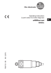
1
Operating instructions
Flow monitors
UK
704194/04 09/2011
SI5006
Contents
1 Preliminary note���������������������������������������������������������������������������������������������������3
1.1 Symbols used������������������������������������������������������������������������������������������������3
2 Safety instructions�����������������������������������������������������������������������������������������������3
3 Functions and features����������������������������������������������������������������������������������������4
3.1 Application area ��������������������������������������������������������������������������������������������4
3.2 Operating principle flow monitoring���������������������������������������������������������������4
4 Installation�����������������������������������������������������������������������������������������������������������5
4.1 Installation location����������������������������������������������������������������������������������������5
4.2 Sources of interference in the pipe system���������������������������������������������������6
4.3 Mounting operation����������������������������������������������������������������������������������������6
5 Electrical connection��������������������������������������������������������������������������������������������7
6 Operating and display elements��������������������������������������������������������������������������8
7 Set-up and settings for water�������������������������������������������������������������������������������8
7.1 Change the switch point (optional)����������������������������������������������������������������9
7.2 High flow adjustment (optional)���������������������������������������������������������������������9
8 Additional settings (optional)������������������������������������������������������������������������������10
8.1 Low flow adjustment������������������������������������������������������������������������������������10
8.2 Configure the switching output��������������������������������������������������������������������10
8.3 Restore the factory setting (reset)���������������������������������������������������������������10
8.4 Lock / unlock the unit�����������������������������������������������������������������������������������10
9 Error during adjustment������������������������������������������������������������������������������������� 11
10 Operation���������������������������������������������������������������������������������������������������������12
11 Maintenance����������������������������������������������������������������������������������������������������12
12 Scale drawing��������������������������������������������������������������������������������������������������13
13 Technical data��������������������������������������������������������������������������������������������������14
2
1 Preliminary note
1.1 Symbols used
►
>
[…]
→
Instruction
Reaction, result
Designation of buttons, switches or indications
Cross-reference
Important note
Non-compliance can result in malfunctions or interference.
UK
2 Safety instructions
• Please read the product description prior to set-up of the unit. Ensure that the
product is suitable for your application without any restrictions.
• The unit conforms to the relevant regulations and EC directives.
• Improper or non-intended use may lead to malfunctions of the unit or to unwanted effects in your application.
• That is why installation, electrical connection, set-up, operation and maintenance of the unit must only be carried out by qualified personnel authorised by
the machine operator.
3
3 Functions and features
3.1 Application area
The unit monitors the flow of liquid and gaseous media.
3.2 Operating principle flow monitoring
• The unit detects the flow speed to the calorimetric measuring principle and
switches the output:
-- output closed if medium is flowing / output open if no medium is flowing.
This applies to the unit on delivery: output = normally open. In case of need you
can change the output to normally closed (→ 8.2). It then applies: output open
if medium is flowing.
• If the flow speed increases, the switching status changes when the switch point
is reached.
• If the flow speed falls again, the switching status changes if the value "SP
minus hysteresis" is reached.
The hysteresis changes with the flow speed and it is essentially influenced by
the set monitoring range.
It is 2...5 cm/s for the setting 5...100 cm/s (= factory setting), it increases with
higher flow speeds.
• The typical response time of the unit is 1...10 s. It can be influenced by the
setting of the switch point:
-- Low switch point = quick reaction with rising flow.
-- High switch point = quick reaction with falling flow.
4
4 Installation
Using process adapters the unit can be adapted to different process connections.
• Adapters have to be ordered separately as accessories.
A correct fit of the unit and ingress resistance of the connection are only ensured using ifm adapters.
• For small flow rates ifm adapter blocks are available.
4.1 Installation location
General
•The sensor tip is to be completely surrounded by the medium.
•Insertion depth of the sensor: minimum
12 mm.
UK
Recommended
•For horizontal pipes: mounting from
the side.
•For vertical pipes: mounting in the rising
pipe.
Conditional
•Horizontal pipe /mounting from the bottom: if the pipe is free from build-up.
•Horizontal pipe /mounting from the
top: if the pipe is completely filled with
medium.
To avoid
•The sensor tip must not be in contact
with the pipe wall.
•Do not mount in downpipes that are
open at the bottom!
5
4.2 Sources of interference in the pipe system
Components integrated in the pipes, bends, valves, reductions, etc. lead to turbulence of the medium. This affects the function of the unit.
Recommendation: Adhere to the distances between sensor and sources of interference:
D = pipe diameter; S = sources of interference
4.3 Mounting operation
►► Ensure that the system is free of pressure during installation.
►► Ensure that no media can leak at the mounting location during installation.
►► Grease the threads of the process connection (1), adapter (2) and nut (3).
Note: The sensor tip (A) must not be in contact with grease.
►► Screw the suitable adapter into the process connection.
►► Place the flow monitor onto the adapter and tighten the nut. Tightening torque
25 Nm. Ensure that the unit is correctly oriented.
6
5 Electrical connection
• The unit must be connected by a qualified electrician.
• The national and international regulations for the installation of electrical
equipment must be adhered to.
• Caution: For the output circuit the same protective measures as
• for the supply circuit must be taken.
• Insert a miniature fuse according to IEC60127-2 Sheet 1 (≤ 5 A fast
acting).
• The permissible potential difference between supply and output circuit is
UK
max. 300 V.
• The equalisation of potential of metal housing parts must be ensured via
the connection flange. Ensure an electrically conductive connection.
• Due to the integrated EMC filters, leakage currents of typ. < 0.5 mA can
flow via the potential equalisation to the earth potential.
• If several units are used in parallel, take into account that the leakage
currents add.
• The applicable standards must be adhered to.
►► Disconnect power.
►► Connect the unit as follows:
A: supply circuit; B: output circuit
: safe separation
ifm-sockets are available as accessories:
Order no. E11248, E11249, E11250, E11251
Core colours of ifm sockets:
1 = BN (brown), 2 = BU (blue), 4 = BK (black), 5 = WH (white)
7
6 Operating and display elements
1: Operation display
•The green LEDs indicate the current flow (the LEDs 0 to 9 represent the range between
no flow and maximum flow).
•A lighting LED indicates the position of the switch point (orange = output closed, red =
output open).
2, 3: Setting buttons for adjustment and configuration
7 Set-up and settings for water
(For media other than water → 8.1: Low flow adjustment).
►► Switch on the supply voltage.
>> All LEDs light and go out again step by step. During this time the output is
closed (if configured as normally open). The unit is in the operating mode.
►► Let the normal flow circulate in the installation.
►► Check the display and determine further actions.
1
2
3
The factory setting is suitable for the application.
►► No further settings are required.
Your normal flow is below the representation
range of the display.
2 setting options:
►► Change the switch point (→ 7.1).
►► Carry out high flow adjustment (→ 7.2).
Your normal flow exceeds the representation
range of the display (LED 9 flashes).
►► Carry out high flow adjustment (→ 7.2).
You can restore the factory setting any time. (→ 8.3).
8
7.1 Change the switch point (optional)
For the factory setting the switch point is at LED 7. A change makes sense in the
folowing cases:
• the display shows example 2.
• the flow fluctuates much or pulsates.
• a faster response time of the unit is requested (low switch point = fast response
with rising flow, high switch point = fast response with falling flow).
or .
►► Briefly press the pushbutton
>> The switch point LED flashes.
UK
►► Press the pushbutton
or
as often as required. Each press of the pushbutton shifts the LED by one position in the indicated direction.
Note: If no pushbutton is pressed for 2 s, the unit returns to the operating mode
with the newly set value.
7.2 High flow adjustment (optional)
The unit determines the existing flow as normal flow and adapts the display representation (all LEDs except the switch point LED light green).
►► Let the normal flow circulate in the installation.
and keep it pressed.
►► Press the pushbutton
>> LED 9 lights, after approx. 5 s it flashes.
►► Release the pushbutton.
The unit is now adapted to your flow conditions. It passes into the operating mode,
the display should now show example 1.
Note: The adjustment affects the switch point: It is increased proportionally (maximum up to LED 7).
9
8 Additional settings (optional)
8.1 Low flow adjustment
If the unit is used in media other than water, you should additionally adapt the unit
to the minimum flow.
Note: The following adjustment must only be carried out after the high flow adjustment.
►► Let the minimum flow circulate in the installation or ensure flow standstill.
and keep it pressed.
►► Press the pushbutton
>> LED 0 lights, after approx. 5 s it flashes.
►► Release the pushbutton. The unit adopts the new value and passes into the
operating mode.
8.2 Configure the switching output
The unit is delivered as normally open. In case of need you can change the output
to normally closed:
for at least 15 s.
►► Press the pushbutton
>> LED 0 lights, after approx. 5 s it flashes.
>> After 10 s the current setting is displayed: LEDs 5...9 light orange (= output
normally open).
>> After approx. 15 s LEDs 0...4 flash orange.
►► Release the pushbutton. The output is changed to normally closed operation.
For a new changeover repeat the operation.
8.3 Restore the factory setting (reset)
►► Press the pushbutton
for at least 15 s.
>> LED 9 lights, after approx. 5 s it flashes.
>> After approx. 15 s LEDs 0...9 flash orange.
►► Release the pushbutton. All settings are reset to the factory setting:
-- operating area: 5 ...100 cm/s for water
-- switch point: LED 7
-- output function: NO
-- unlocked.
8.4 Lock / unlock the unit
The unit can be locked electronically to prevent unintentional settings.
10
►► Press both setting pushbuttons simultaneously for at least 10 s in the operating
mode.
>> The indication goes out, the unit locks or unlocks.
On delivery: unlocked.
9 Error during adjustment
If no adjustment is possible, all LEDs flash red. The unit then passes into the
operating mode with unchanged values.
Possible cause /aid:
UK
Error during installation.
►► Read chapter 4 Installation.
Check whether all requirements have
been met.
The difference between maximum flow and
minimum flow is too small.
►► Increase the flow difference and carry
out the adjustment once again.
The sequence high flow /low flow adjustment was not adhered to.
►► Carry out the two adjustment operations
again in the right sequence.
11
10 Operation
After every power on all LEDs light and go out again step by step (during this time
the output is closed if configured as normally open). The unit is then ready for
operation.
In case of power failure or interruption all settings remain.
Operating indicators
Green LED bar: Current flow within the representation range.
Indication of the switch point (SP):
- LED orange: output closed.
- LED red: output open.
LED 9 flashes: current flow above the
representation range.
LED 0 flashes: current flow far below the representation range.
Interference indicators
Display OFF
(no LED lights):
Operating voltage too low (< 85 V AC) or failed.
Ensure a correct voltage supply.
11 Maintenance
Recommended maintenance:
►► Check the sensor tip for build-up from time to time.
►► Clean it using a soft cloth. Stubborn build-up (e.g. lime) can be removed using
a common vinegar cleaning agent.
12
12 Scale drawing
2
1
63
20UNF 2A
27
50
14
113
1 2"
UK
45
60
65
22
3
8,2
1: LED bar display
2: set button
3: tightening torque 25 Nm
13
13 Technical data
Application area.........................................................................................Liquids and gases
Nominal voltage [V]......................................................................90 ... 240 AC (45....65 Hz)
Voltage tolerance [%]................................................................................................ -5 / +10
Operating voltage [V].........................................................................................85 ... 265 AC
Power consumption [VA]...................................................................................................3.5
Relay type:.........................................................................................contact closed at work
Switching power of relay............................................................... 3 A (250 V AC / 30 V DC)
Number of switching cycles...............................................................20 million mechanically
Switching cycles with 3 A load.................................................................100.000 electrically
Power-on delay time [s]....................................................................... 10, optically indicated
Liquids
Medium temperature [°C]..................................................................................... -25 ... +80
Setting range [cm/s]..................................................................................................3 ... 300
Greatest sensitivity [cm/s] ..........................................................................................3...100
Temperature gradient [K/min] ..........................................................................................300
Gases
Medium temperature [°C]..................................................................................... -25 ... +80
Setting range [cm/s]............................................................................................200 ... 3000
Greatest sensitivity [cm/s].....................................................................................200 ... 800
Switch point accuracy [cm/s].................................................................................± 2...± 101)
Hysteresis [cm/s]...........................................................................................................2...51)
Repeatability [cm/s].......................................................................................................1...51)
Temperature drift [cm/s x 1/K].........................................................................................0.12)
Response time [s]........................................................................................................1 ... 10
Pressure resistance [bar].................................................................................................300
Operating temperature [°C]................................................................................... -25 ... +80
Protection rating / Protection class........................................................................... IP 67 / II
Shock resistance [g]............................................................... 50 (DIN / IEC 68-2-27, 11 ms)
Vibration resistance [g].................................................... 20 (DIN / IEC 68-2-6, 55-2000 Hz)
Housing materials.......................stainless steel 316L / 1.4404; stainless steel 304 / 1.4301;
PC (Makrolon); PBT-GF 20; EPDM/X (Santoprene)
Materials (wetted parts)........................................................... stainless steel 316L / 1.4404;
O-ring: FPM 8x1.5 gr 80° Shore A
EMC: EN 61000-4-2 ESD: ...................................................................... 4 kV CD / 8 kV AD
EN 61000-4-3 HF radiated: ............................................................................ 10 V/m
EN 61000-4-4 Burst: ........................................................................................... 2 kV
EN 61000-4-6 HF conducted: ............................................................................. 10 V
1)
for water; 5...100 cm/s; 25°C (factory setting);
2)
for water; 5...100 cm/s; 10...70°C
More information at www.ifm.com
14