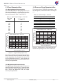
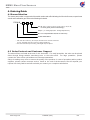
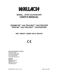
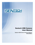
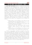
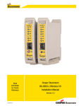
1
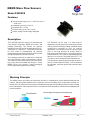
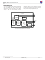
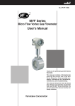
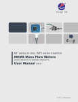
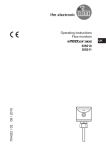
Model FS5001B
SIARGO MEMS FLOW SENSOR PRODUCTS
MEMS Mass Flow Sensors
VA.0
© 2014 Siargo Ltd.
MEMS Mass Flow Sensors
FS5001B Series
User Manual
Document No.
Issue date:
Revision:
07-2014-S0 EN
2014.07
VA.0
Siargo Ltd.
2041 Mission College Boulevard
Suite 250
Santa Clara, CA 95054
USA
Tel: +1(408)969.0368
Email: [email protected]
© Copyright 2014 by Siargo Ltd.
Siargo Ltd. and its subsidiaries reserve the rights to change the specifications and/or
descriptions without prior notice. For further information and updates, please visit:
www.Siargo.com
MEMS Mass Flow Sensors
Model FS5001B
Features
Low mass flow range from 0 ~ 200 sccm up to 0
~ 1000 sccm
Outstanding accuracy of ±2.0 %
Response time < 10 ms
Pressure rating up to 5 bar (73 psi)
Output: analog or both analog and digital
Description
The FS5001B mass flow sensors are manufactured
using Siargo’s proprietary MEMS flow sensor and
package technology. The sensors are specially
designed for low flow rate range applications from 0 ~
200 sccm to 0 ~ 1000 sccm. The maximum flow rate
for each model is manufactured via specially
designed package as well as smart electronics so that
the optimal sensitivity would be achieved.
The packaging enclosure is made of the chemically
inert and thermally stable polycarbonate material.
The maximum over pressure rating can reach up to 5
bar (73 psi) that is benefitted from Siargo’s unique
MEMS sensor chip structure, special packaging
technology and the rugged sensor housing.
The FS5001B can be used in a wide range of
applications including mass flow metering for process
control, gas flow metrology, heating ventilation and air
conditioning solutions as well as medical
applications. The FS5001B requires a power supply
of 8 ~ 15 Vdc and provides an analog output or
both analog and digital outputs. The analog output is
linearized from 0.5 to 4.5 Vdc corresponding with flow
2
rate from 0 to full scale. The digital output is I C. The
2
I C protocol can be obtained from the manufacturer.
The calibration is generally performed with air at 20 °C
and 101.325 kPa pressure rating. It can nonetheless
be calibrated with other gases and conditions upon
requests.
Working Principle
The MEMS sensor chip utilizes the calorimetric principle. It is packaged on a plate installed inside the flow
channel, which provides additional flow conditioning from the boundary layer configuration resulting in a
laminar flow. The mass flow measurement is established as the gas carries heat away from the heater leading
to the redistribution of the temperature field. Accurate flow rate is obtained by calibration with standard gas at
preset conditions.
Flow direction
Time-averaged velocity profile boundary layer
Turbulent
Free stream
Laminar
Sensor
www.siargo.com
FS5001B (VA.0)
1/8
MEMS Mass Flow Sensors
Block Diagram
The functional block diagram is shown in the following
figure. The MEMS sensor chip is powered by the
sensor driving circuitry and sends flow rate related
voltage to ADC. The micro-controller processes
(amplifying, filtering, etc) the voltage then converts
into flow rate. The flow rate signal is sent out through
2
analog or both analog and digital formats (I C).
FS5001B
VCC
GND
Voltage
Flow
Regulator
EEPROM
SDA (I2C)
MEMS
Sensor
Chip
Sensor
Driving
Circuitry
SCL (I2C)
ADC
MUC
D/A
I/V
Converter
Vout
Functional block diagram of the FS5001B.
www.siargo.com
FS5001B (VA.0)
2/8
MEMS Mass Flow Sensors
1. Sensor Performance
1.1 Performance Specifications
All data unless otherwise noted apply for calibration conditions: N2, 20°C, 101.325kPa absolute pressure, horizontal
mounting.
Model
FS5001B
Flow Range
0 ~ 200, 500, 1000
Turn-down Ratio
sccm
100:1
1
±(2.0 ± 0.5FS)
%
Repeatability
± 0.5
%Reading
Null Shift
± 30
mV
± 0.12
%/° C
10 (Default, 5, 10, 20, 50, 100, 200, 500, 1000 selectable)
ms
Accuracy
Output Shift
Response Time
2
2
Linear: I C, Analog 0.5 ~ 4.5 Vdc
Output
Pressure Drop
3
Working Pressure
Power Supply
4
< 900
Pa
-0.08 ~ +0.5
MPa
8 ~ 15 Vdc, 50 mA
Operating Current
Power Consumption
20 mA
mA
<220
mW
Sourcing: 25
Analog Output Load
mA
Sinking: 15
-5 ~ +45
Working Temperature
°C
1 Denotes ±(2.0 %Reading + 0.5 %Full Scale). To obtain accurate flow measurement, let the sensor warm up 1 minute at power up.
2 The response time is determined by ADC sampling rate and data process algorithm. The default response time is 10 ms. It can be programmed
via I2C communication.
3 The maximum pressure drop is measured at flow rate 1000 sccm. For lower range flow sensors, the pressure drop will be smaller. See section 1.4
for details.
4 One DC power supply is necessary. The required minimum output current is 50 mA. The sensor actually consumes less than that in operation.
1.2 Additional Specifications
Pins Out
5 Pin, 2.54 mm centers, 0.635 mm square
Calibration Options
Air @ 20 ° C, 101.325 kPa
Packaging material
Polycarbonate
Dimensions
Weight
Srorage Temperature
Humidity
www.siargo.com
3
39.6 x 36.3 x 15.7
mm
15
g
-20 ~ +55
°C
<95 %RH (No icing or condensation)
FS5001B (VA.0)
3/8
MEMS Mass Flow Sensors
1.3 Flow Characteristics
1.4 Pressure Drop Characteristics
1.3.1 Analog Output Characteristics
The pressure drop of FS5001B is dependent on the
flow rate applied, it is illustrated in Table 1.2 and Figure
1.2.
The FS5001B provides an analog output of 0.5 ~ 4.5
Vdc corresponding with 0 ~ full scale flow rate. Using
500 sccm as an example, the typical analog output v.s.
flow rate is illustrated in Table 1.1 and Figure 1.1.
Table 1.2: Pressure drop v.s. flow rate.
Table 1.1: Typical output voltage v.s. flow rate.
Flow Rate
(sccm)
Typical Voltage
(Vdc)
0
0.5
100
1.3
200
300
2.1
2.9
3.7
400
500
550
600
Pressure Drop (Pa)
0
200
400
600
800
1000
4.5
4.9
4.9
0
50
150
320
560
850
Pressure Drop (Pa)
Pressure Drop Curve - 1000 sccm
Typical Output Curve - 500 sccm
Analog Output Voltage (V)
Flow Rate (sccm)
5.0
4.5
4.0
3.5
3.0
2.5
2.0
1.5
1.0
0.5
0.0
900
800
700
600
500
400
300
200
100
0
0
200
400
600
800
1000
Mass Flow Rate (sccm)
0
100
200
300
400
500
600
Figure 1.2: Pressure drop v.s. flow rate for sensors
with the same package for full scale of 1000 sccm.
Mass Flow Rate (sccm)
Figure 1.1: A typical analog output curve.
The sensor is calibrated 10% above the full scale flow
rate to ensure the accuracy within the defined range
during interpolation. For example, full scale of 500
sccm is calibrated till 550 sccm. Hence at flow rate
beyond the full scale, there is still analog output but the
accuracy is not guaranteed.
1.3.2 Digital Output Characteristics
2
The digital output is delivered through I C. Figure 1.2
shows the applied mass flow rate v.s. the digital output
of the 1000 sccm. Same as analog output, when flow
rate is beyond the defined full scale, the output
accuracy is not guaranteed.
www.siargo.com
FS5001B (VA.0)
4/8
MEMS Mass Flow Sensors
2. Pins and Interface
2.2 Pin Description
2.1 Pin Definition
VCC and GND: The FS5001B requires a power supply
of 8 ~ 15 Vdc. The voltage is internally regulated to
power the circuitry. Therefore, there is no stringent
requirements on the accuracy, stability as well as
ripple of the external supply.
Vout: The analog output pin provides 0.5 ~ 4.5 Vdc
corresponding with the specified flow range 0 ~ full
scale. Beyond this range, there is still voltage reading,
but the accuracy is not guaranteed.
SDA and SCL: For I2C, please contact Siargo for
protocol.
The FS5001B provides 5 pin interface. The pin layout
and definition are as Figure 2.1 and Table 2.1.
P1 - Inlet
P2 - Outlet
12345
Figure 2.1: FS5001B pin configuration.
Table 2.1: FS5001B pin definition.
Pin Num.
Definition
1
SDA (I2C)
2
Vout, Analog output
3
VCC, Power supply
4
GND, Ground
5
SCL (I C)
2
3. Mechanical Dimensions and Mountings
3.1 Sensor Mechanical Dimensions
3
The FS5001B has a dimension of 39.6 x 36.3 x 15.7 mm . The dimension is illustrated in Figure 3.1.
Figure 3.1: Mechanical dimensions of the FS5001B.
www.siargo.com
FS5001B (VA.0)
5/8
MEMS Mass Flow Sensors
4. Ordering Guide
4.1 Sensor Selection
The sensor part number is composed of the model number and suffix indicating the full scale flow rate, output format
as well as the calibration gas. Refer to the followings for details.
FS5001B
Gas (A - air; C - CO2; E - He; H - H2; N - N2; O - O2; R - Ar;
For other gases, please contact Siargo.)
Output** ( V - analog output; EV - analog output and I2C)
Max. flow rate*(selectable: 200, 500 or 1000 sccm)
Product Series Name
* Max. flow rate number only, for example, 500 means max. flow rate of 500 sccm.
For CO2, selectable: 200, 500 or 750 sccm (without 1000sccm);
** The sensor standard output is analog, while digital output is optional.
4.3 Order Contact and Customer Suppor t
The sales offices are listed at the end of this document . For small quantities, the order can be placed
either through Siargo website: www.siargo.com or the sales office . For large quantities , please
contact the sales office or distributors or sales representatives.
Siargo is making every effort to ensure the quality of the products. In case of questions and/or product
supports, please contact customer service listed at the end of the document. We will respond your
request in a timely fashion and will work with you toward your complete satisfaction.
www.siargo.com
FS5001B (VA.0)
6/8
MEMS Mass Flow Sensors
Important Notices
Wetted Materials and Compatibility
The sensor body is made of medical compatible
plastics. The sensor chip comprises of silicon, silicon
nitride and silicon dioxide and the sensor chip surfaces
are passivated with silicon nitride and silicon dioxide.
The electronic sealing is provided by RTV (room
temperature vulcanizing) silicone sealant WR-704
composed of HOCH3 (SiO) nCH3H.
Cautions for Handling and
Installations
The product at the time of shipment is fully inspected
for product quality and meets all safety requirements.
Additional safety measures during handling and
installation should be applied. To prevent ESD
(electrostatic discharge) damage and /or degradation,
take customary and statutory ESD precautions when
handling. Do power the product with the correct
polarity, voltage and amperage. All precautions and
measures for electrical voltage handling must apply.
The product sealing is ensured to work under
working pressure of 0.5MPa and is leakage proof
before the shipment. But cautions and further
leakage test are important at installation as well since
any leakage may cause severe safety issues.
This product contains no user serviceable
components. Do not attempt to disassemble,
substitute parts or perform unauthorized modifications
to the product. Doing so will forfeit the terms of the
warranty and cause the liability to any damages
thereafter. The product should only be serviced by
authorized personnel. Upon requests, Siargo will
provide necessary technical support and/or training of
the personnel.
Cautions for Product Applications
The product is designed for use with general purpose
gases such as air and nitrogen. It is advised that the
products are best used for non-explosive clean gases.
The sensors cannot be used for gas metrology of
fluoride or fluoride-containing gases. For updates of
the product certification information, please contact
the manufacturer. Use for other gases such as
extreme corrosive and toxic gases may cause the
product malfunctioning or even severe damages.
Don’t expose the product’s outer surface to any
liquids, the unit does not have a water tight electronics
package.
Don’t flow gas in conditions that can cause
condensing water vapor to be trapped inside the unit
as the accuracy could be significantly altered.
flow rate of the sensor. Don’t use a sensor with an
extreme flow rate , for instance, don’t use a 1000sccm
sensor for a 10 sccm application.
Warranty and Liability
(effective March 2009)
Siargo warrants the products sold hereunder,
properly used and properly installed under normal
circumstances and service as described in the user
manual, shall be free from faulty materials or
workmanship for 180 days for OEM products, and
365 days for non-OEM products from the date of
shipment. This warranty period is inclusive of any
statutory warranty. Any repair or replacement serviced
product shall bear the same terms in this warranty.
Siargo makes no other warranty, express or
implied and assumes no liability for any special
or incidental damage or charges, including but
not limited to any damages or charges due to
installation, dismantling, reinstallation or any
other consequential or indirect damages of any
kind. To the extent permitted by law, the
exclusive remedy of the user or purchaser, and
the limit of Siargo ' s liability for any and all
losses, injuries or damages concerning the
products including claims based on contract,
negligence, tort, strictly liability or otherwise
shall be the return of products to Siargo, and
upon verification of Siargo to prove to be
defective, at its sole option, to refund, repair or
replacement of the products. No action,
regardless of form, may be brought against
Siargo more than 365 days after a cause of
action has accrued. The products returned
under warranty to Siargo shall be at user or
purchaser's risk of loss, and will be returned, if
at all, at Siargo’s risk of loss. Purchasers or
users are deemed to have accepted this
limitation of warranty and liability, which
contains the complete and exclusive limited
warranty of Siargo, and it shall not be amended,
modified or its terms waived except by Siargo ' s
sole action.This warranty is subject to the
following exclusions:
(1) Products that have been altered, modified or
have been subject to unusual physical or
electrical circumstances indicated but not
limited to those stated in this document or
any other actions which cannot be deemed
as proper use of the products;
(2) Siargo does not provide any warranty on
finished goods manufactured by others. Only
the original manufacturer's warranty applies;
(3) Products re-sold to the third parties.
It is suggested to design your application so that
nominal flow rate is approximately 70% of the full scale
www.siargo.com
FS5001B (VA.0)
7/8
MEMS Mass Flow Sensors
Contact Information
Headquarters
Siargo Ltd.
2041 Mission College Blvd., Suite 250,
Santa Clara, California 95054 USA,
Phone: +01(408)969-0368
Email: [email protected]
Representative in US
Sentech Measurements, Inc.
P.O. Box 675265
6916 Circo Diegueno Court
Rancho Santa Fe, California 92067
Phone: +01-858-759-0613
Email: [email protected]
Representative in Japan
Marubeni Information Systems Co., Ltd.
Device Solutions Department
3-12-18 Shibuya,
Shibuya-ku, Tokyo 150-0002 Japan
Phone: +81-3-5778-8661
Representative in Europe
IDENTIC Stefanie Trojan
Roehlichstrasse 19
68723 Oftersheim Germany
Phone: +49-(0)6202-574198
Email: [email protected]
This document is intended for distribution to interested customer(s) only. Siargo and its subsidiaries reserve the
rights to change the specifications and/or descriptions without prior notice.
www.siargo.com
FS5001B (VA.0)
8/8