1
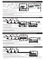
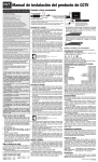
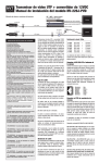
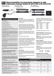
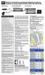
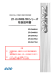
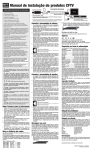
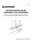
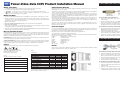
Power-Video-Data CCTV Product Installation Manual
Wiring Safety Notes
Limited Lifetime Warranty
1. This installation should be made by a qualified service person and should conform to all local codes.
NVT warrants that the product conforms to NVT’s applicable published specifications and is free of defects and
workmanship, for the life of the product.
2. For safety, never put NVT signals in the same conduit as high-voltage wiring.
3.
4.
WARNING – to reduce a risk of fire or electrical shock, do not expose this product to rain or moisture.
WARNING – the apparatus shall not be exposed to dripping or splashing and no objects filled with
liquids, such as vases, shall be placed on the apparatus.
Wiring Tech Notes
1. Use point-to-point Unshielded Twisted Pair wire, 24-16 AWG (0,5-1,3mm), stranded or solid, Category 2 or better.
2. The Video signal may co-exist in the same wire bundle as other Video, telephone, Data, control signals, or lowvoltage Power. It is also OK to run NVT Video signals in or near electromagnetic fields (in accordance with National
Electrical Code, local, or other local safety requirements).
3. Measure the wire distance.
Power-Video Fixed camera single channel application
There shall be no other warranties, express, statutory or otherwise, including any implied warranty of merchantability
of fitness or any other obligation on the part of NVT with respect to any of the products.
In the event that any product is damaged or altered or modified without the express written consent of NVT, any
warranty for those products will cease and NVT will have no further liability as it pertains to those products. NVT
assumes no responsibility for damages or penalties incurred resulting from the use of this product in a manner or location other than for which it is intended.
NVT’s liability under any warranties shall be discharged by replacing or repairing any part or parts which do not
conform to the applicable warranty under normal and proper use. NVT’s liability with respect to any product shall not
exceed a refund of the price received by NVT for that product, and in no event shall NVT have any liability for any
incidental, consequential, special, or indirect damages.
Power and Video at the Camera End
1. Connect the baseband Video signal output from the camera to the male BNC on the NV-216A-PV
or NV-218A-PVD.
2. Connect the camera’s Power input to the 18AWG Power wires on the NV-216A-PV or NV-218A-PVD. Verify wire
distance, camera load and wire resistance limit for the maximum distance that Power can travel using Figure #2.
5. DON’T USE UN-TWISTED WIRE.
Some states do not allow the exclusion or limitation of special, incidental or consequential damages, so the above
limitation or exclusion may not apply to you. This warranty gives you specific legal rights, and you may also have other
rights which vary from state to state.
6. Due to near-end crosstalk, don’t send a transmit and a receive signal in the same wire bundle. Exceptions: Less than
1,000 ft (300m), or Category 5 or better cable, up to 2,000 ft (600m) are OK.
Customer Support
Connecting the Power-Video at the Equipment Room End
If you are experiencing problems, attempt to simplify your setup. Test each cable segment separately. For example, test
the camera and monitor together without the other equipment. Then add in the NVT transceivers, back-to-back. Test
each segment of a long cable-run independently. Attempt to isolate the problem.
1. Connect the baseband Video input twisted pair to the screwless terminals adjacent to the RJ45 connector of the
NV-218A-PVD, or using the 8-pin RJ45 connector on the NV-216A-PV or
NV-218A-PVD as shown in Figure #3 below.
NVT customer support can be reached 8:00 AM to 5:30 PM PST at (800) 959-9870, at
(+1) (650) 462-8100 or our UK office at (44) (0) 20-8977-6614.
2. Connect the baseband Video signal output from the BNC pigtail on the NV-218A-PVD or the BNC of the NV-216A-PV
directly to the Video monitor, multiplexer, or DVR.
NVT customer support is available for consultation from 8:00 AM to 5:30 PM PST Monday through Friday. In addition,
emergency after-hours callback support is available.
3. Connect Power via a Class II (SELV) low-voltage Power supply. NVT recommends the use of 18AWG solid wire.
NVT also recommends Power supplies with individually floating outputs.
4. DON’T USE SHIELDED TWISTED PAIR WIRE. Multi-pair (6 pair or more) wire with an overall shield is OK.
7. Don’t send “Up-the-Coax” Pan/Tilt/Zoom signals through active (amplified) NVT transceivers. Passive NVT transceivers will
transmit “up the coax” P/T/Z control signals up to 750ft (225m).
Measure Your Wire Distance
All NVT quoted distance specifications include any coax in the run. It is recommended that the wire distance be measured
to ensure that the capability of the NVT product is correct. Wire should be Category UTP cable. Lowvoltage camera Power, Video, and RS-422 or RS-485 may be sent within the same wire bundle. Do not run 24VAC or
28VAC in the same wire bundle with other Telecom or Datacom signals.
Video Distance: Wire resistance may be measured with an ohm-meter by shorting the two conductors together at the
far end, and measuring the loop-resistance out and back. See Figure 1.
Camera Power Distance: Different cameras draw different amounts of current. It is important to make sure that the
voltage-drop on the wire allows sufficient voltage for the camera to operate properly. A camera voltage of 21VAC or
greater is usually acceptable. Figure 2 shows typical wire distances for standard camera configurations.
Agency
These NVT products are listed and/or conform to the following certifications and directives:
US Office:
US Fax:
UK Office:
UK Fax:
Email USA:
Email UK:
Web home page:
(800) 959-9870 or (+1) (650) 462-8100
(+1) (650) 326-1940
(+44) (0)20 8977 6614
(+44) (0)20 8973 1855
[email protected]
[email protected]
nvt.com
3. Connect the 4-pair Cat-5 using the NV-216A-PV’s or NV-218A-PVD’s 8-pin RJ45 connector on the UTP run to
the Equipment Room as shown in Figure #3 below.
Power-Video-Data P/T/Z camera single channel application
Returns
Please call before returning units to NVT. Returned materials must have a “Returned Materials Authorization” (RMA)
number from NVT marked on the outside of the shipping carton.
UL Listed to UL2044 or UL/IEC 60065.
cUL Listed to CAN/CSA22.2 No. 1 for Canada.
CE Mark under EMC and low voltage
Directives for the European Union.
Figure 2
Power-Distance
Figure 3
Camera Pinouts & UTP Wire Colors
1.
Powering Your Camera Using UTP and NVT
Figure 1
Resistance per 1,000 ft (300 m) out and back
24AWG (0,5mm)
= 52 Ohms per 1000ft (300m)
22AWG (0,6mm)
= 32 Ohms per 1000ft (300m)
= 20 Ohms per 1000ft (300m)
19AWG (0,8mm)
= 16 Ohms per 1000ft (300m)
18AWG (1,0mm)
= 13 Ohms per 1000ft (300m)
16AWG (1,3mm)
= 8.2 Ohms per 1000ft (300m)
Connect the baseband Video signal output from the camera to the Male BNC pigtail connector on the NV-218A-PVD.
Power Supply Voltage
28 VAC
24 VAC
12 VDC
2. Connect the camera’s Power input to the screwless terminals marked Power on the NV-218A-PVD. Verify wire
distance, camera load and wire resistance limit for the maximum distance that Power can travel using Figure #2.
100 mA Camera
2-pair 24 AWG
2,150 ft*
920 ft*
190 ft*
3. If the camera supports P/T/Z telemetry over RS-422 or RS-485, connect the camera’s Data terminals to the Data
screwless terminals on the NV-218A-PVD.
2, 700 ft*
1,160 ft*
240 ft*
2-pair 23 AWG (Cat6)
20AWG (0,7mm)
Connecting Power-Video-Data at the Camera End
300 mA Camera
2-pair 24 AWG
2-pair 23 AWG (Cat6)
1 Amp Camera
2-pair 24 AWG
710 ft*
300 ft*
60 ft*
900 ft*
380 ft*
80 ft*
210 ft*
90 ft*
15 ft*
*Actual distance will depend on the camera’s inrush & operating current, minimum
operating voltage, and the wire’s environmental temperature. Please consult NVT
Customer Support for further information.
4.
Figure 4
Control End Pinouts
Connect the 4-pair Cat-5 using the 8-pin RJ45 connector on the UTP run to the Control end as shown in Figure #3 below.
Connecting the Power-Video-Data at the Equipment Room
1. Connect the 4-pair Cat-5 from the camera end to the RJ45 connector on the NV-218A-PVD.
2. Connect the baseband Video signal output from the BNC pigtail on the NV-218A-PVD directly to the Video monitor,
multiplexer or DVR.
3. Connect the control equipment data port to the screwless terminals marked data on the NV-218A-PVD.
4. Connect the Power screwless terminals to a Class II (SELV) low-voltage Power supply. NVT recommends the use
of 18AWG solid wire. NVT also recommends Power supplies with individually floating outputs.
Power-Video-Data 4-Channel Application using the NV-704J-PVD at the Telecommunications Closet or IDF
Control Room / MDF
DVR
NV-413A or NV-452R
Cat5
Cat5
Four Video Signals
Optional RS-422 / 485 P/T/Z telemetry data
Power-Video-Data at the Camera End
4 Output low-voltage
POWER SUPPLY
1. Connect the NV-216A-PV or the NV-218A-PVD as shown in the
examples on the other side.
2. Connect the 4-pair Cat5 UTP cables coming from the cameras into the
appropriate camera port on the NV-704J-PVD using the RJ45 connector
as shown in Figure 3.
3. Connect the outputs of your independent power supply into the appropriate Camera Power terminals on the NV-704J-PVD. Torque to 2 in-lbs (0.22 Nm). NVT recommends the use of 18AWG (1,0 mm)
solid conductor wire. NVT also recommends that the external power supply have individually floating outputs.
Power-Video-Data at the Equipment Room End
4. Connect the NV-704J-PVD’s Control Room outputs to the NV-413A or NV-452R via UTP using RJ45 connectors and Cat5 cable. The control end pinouts are listed in Figure 4. If P/T/Z telemetry is required,
connect a second RJ45 Cat5 cable from the data port to the DVR’s RS-422 or RS-485 control output.
Power-Video-Data 16-Channel Application using the NV-716J-PVD at the Telecommunications Closet or IDF
NV-216A-PV
NV-218A-PVD
Fixed Camera
w/built-in NVT
P/T/Z dome
w/built-in NVT
Wiring / IDF Telecom Closet
RJ45 Patch-cords
RJ45 Wall Plates
Control Room / MDF
25-pair
UTP
24-Port Patch-panel
4-pair UTP Cat5 or better
1
1
Power-Video-Data at the Camera End
1. Connect the NV-216A-PV or the NV-218A-PVD
as shown in the examples on the other side.
2
1
3
1
4
1
NV-716J-PVD
5
1
TM
Camera 1
6
1
Camera 2
7
1
Camera 3
8
1
Camera 4
Camera 5
1
9 10 11 12 13 14 15 16 17 18 19 20 21 22 23 24
1
1
Camera 6
Camera 7
1
1
Camera 8
Camera 9
1
1
1
Camera 10 Camera 11 Camera 12
1
1
1
1
Camera 13 Camera 14 Camera 15 Camera 16
1
Ports 1-4
1
Ports 5-8
1
1
Ports 9-12 Ports 13-16
1
3
1
4
1
5
1
6
1
7
1
8
1
9 10 11 12 13 14 15 16 17 18 19 20 21 22 23 24
1
1
1
1
1
1
1
1
1
1
1
1
1
1
1
24-Port Patch-panel
1
P/T/Z
Telemetry
Data
Telemetry
Control Room Video
Camera Power In
Low Voltage SELV
Class 2 only. See manual.
2
1
1
NV-716J-PDU Video / Power / Telemetry Termination Panel
NV-1613J or NV-1662J
DVR
Multi-Output Power Supply
2. Connect the 4-pair Cat5 UTP cables coming
from the cameras into the appropriate camera
port on the NV-716J-PVD using the RJ45 connector as shown in Figure 3.
3. Connect the outputs of your independent power supply into the appropriate Camera Power terminals on the NV-716J-PVD. Torque to 2 in-lbs (0.22 Nm) Figure 4. NVT recommends the use of 18AWG
(1,0 mm) solid conductor wire. NVT also recommends that the external power supply have individually floating outputs.
Power-Video-Data at the Equipment Room End
4. Connect the NV-716J-PVD’s Control Room outputs to the NV-1613J or NV-1662J via UTP using RJ45 connectors and Cat5 cable. The pinouts are listed in Figure 4. If P/T/Z telemetry is required, connect
additional RJ45 Cat5 cable(s) from the data port(s) to the DVR’s RS-422 or RS-485 control output. Additional details can be found in the NV-716J-PVD installation manual, or at www.nvt.com.
Power-Video-Data 16-Channel Application using the NV-16PS10-PVD Power Supply Cable Integrator
NV-216A-PV
NV-218A-PVD
Fixed Camera
w/built-in NVT
P/T/Z dome
w/built-in NVT
Wiring / IDF Telecom Closet
NV-16PS10-PVD
1
2
24V
28V
3
24V
28V
4
24V
28V
5
24V
28V
6
24V
Control Room / MDF
Network Video Technologies
NV-16PS10-PVD Mid-Span Power Supply Hub
Power
28V
7
24V
28V
8
24V
28V
9
24V
28V
10
24V
28V
11
24V
28V
12
24V
28V
13
24V
28V
14
24V
28V
15
24V
28V
16
24V
28V
24V
28V
TM
NVT
RJ45 Patch-cords
RJ45 Wall Plates
1
1
1
2
1
1
1
3
1
4
1
4-pair UTP Cat5 or better
1
5
1
1
6
1
1
7
1
8
1
1
1
1
1
1
1
1
1
1
1
1
9 10 11 12 13 14 15 16 17 18 19 20 21 22 23 24
1
1
1
1
1
1
1
1
1
1
1
1
1
1
1
1
25-pair
UTP
24-Port Patch-panel
Power-Video-Data at the Camera End
1.Connect the NV-216A-PV or the NV-218A-PVD as shown in the examples on the other side.
1
2
1
1
3
1
4
1
5
1
6
1
7
1
8
1
9 10 11 12 13 14 15 16 17 18 19 20 21 22 23 24
1
1
1
1
1
1
1
1
1
1
1
1
1
1
1
1
P/T/Z
Telemetry
Data
24-Port Patch-panel
NV-1613J or NV-1662J
DVR
2.Connect the 4-pair Cat5 UTP cables coming from the cameras into the appropriate camera
port on the NV-16PS10-PVD using the RJ45 connector as shown in Figure 3.
Power-Video-Data at the Equipment Room End
3. Connect the NV-16PS10-PVD’s Control Room outputs to the NV-1613J or NV-1662J via UTP using RJ45 connectors and Cat5 cable. The pinouts are listed in Figure 4. If P/T/Z telemetry is
required, connect additional RJ45 Cat5 cable(s) from the data port(s) to the DVR’s RS-422 or RS-485 control output. Additional details can be found in the NV-16PS10-PVD installation
manual, or at www.nvt.com.
Power-Video-Data 8 or 16-Channel Application using the NV-8PS13-PVD or NV-16PS13-PVD
NV-216A-PV
NV-218A-PVD
Fixed Camera
w/built-in NVT
P/T/Z dome
w/built-in NVT
Wiring / IDF Telecom Closet
RJ45 Patch-cords
RJ45 Wall Plates
Patch-panel
4-pair UTP Cat5 or better
1
1
Power-Video-Data at the Camera End
1. Connect the NV-216A-PV or the NV-218A-PVD as shown in the examples on the other side.
2. Connect the 4-pair Cat5 UTP cables coming from the cameras into the appropriate camera
port on the NV-PS13 (8-port) or the NV-16PS13-PVD (16 port) using the RJ45 connector as shown in Figure 3.
NV-8-PS13-PVD
or NV-16PS13
IP Network Digitizer
2
1
3
1
4
1
5
1
6
1
7
1
8
1
9 10 11 12 13 14 15 16 17 18 19 20 21 22 23 24
1
1
1
1
1
1
1
1
1
1
1
1
1
1
1
2
24V
28V
3
24V
28V
4
24V
28V
5
24V
28V
6
24V
1
P/T/Z
Telemetry
Data
Network Video Technologies
NV-16PS10-PVD Mid-Span Power Supply Hub
Power
1
28V
7
24V
28V
8
24V
28V
9
24V
28V
10
24V
28V
11
24V
28V
12
24V
28V
13
24V
28V
14
24V
28V
15
24V
28V
16
24V
28V
24V
28V
TM
NVT
1
1
1
1
1
1
1
1
1
1
1
1
1
1
1
1
1
Ethernet Out
3.Connect the NV-8PS13-PVD’s or NV-16PS13-PVD’s BNC outputs to your DVR/MVR or IP digitizer. If P/T/Z telemetry is required, connect additional RJ45 Cat5 cable(s) from the NV-8PS13-PVD’s
or NV-16PS13-PVD’s data port(s) to the DVR/MVR or IP digitizer’s RS-422 or RS-485 control output. Additional details can be found in the NV-8PS13-PVD or NV-16PS13-PVD installation
manual, or at www.nvt.com.
Copyright (c) 2006 NVT, Inc. 451-218-1-D