Download User's Manual Rev 001a
Transcript
User’s Manual Rev 001a FCC Notice The DC5 has been tested and found to comply with the limits for Class A digital devices, pursuant to Part 15 of the FCC Rules. These limits are designed to provide reasonable protection against harmful interference when the equipment is operated in a commercial environment. The cutters generate, use and can emit radio frequency energy and, if not installed and used in accordance with the instruction manual, may cause harmful interference to radio communications. Operation of the cutters in a residential area is likely to cause harmful interference, in which case the user will be required to correct the interference at his own expense. Caution! Changes or modifications not expressly approved by Summa, which is responsible for FCC compliance, could void the user’s authority to operate this equipment. DOC Notice The DC5 does not exceed the Class A limits for radio noise for digital apparatus set out in the Radio Interference Regulations of the Canadian Department of Communications. Notice Summa reserves the right to modify the information contained in this User Manual at any time without prior notice. Unauthorized copying, modification, distribution or display is prohibited. All rights reserved. Waste Electrical and Electronic Equipment (WEEE) Directive Directive 2002/96/EC of the European Parliament and of the Council The symbol (right) is shown on this product. It indicates that the product should not be disposed of with regular household waste, but should be disposed of separately. Electrical and electronic equipment can contain materials that are hazardous to the environment and human health and therefore should be disposed of at a designated waste facility or returned to your retailer for the appropriate recycling to take place. If you wish to dispose of this product and the product still functions, please consider recycling/reusing it by donating it to a charity shop, selling it or part-exchanging it with your retailer. Copyright © Summa Registering Your Printer Please register your printer on the following link: http://www.summa.be/registration.html Failure to register may result in delayed responses to your warranty and service inquiries. Contact Information All inquiries, comments or suggestions concerning this and other Summa manuals should be directed to: North America and Asia Pacific Eastern United States and Latin America Europe, Africa and Middle East Summa, Inc 10001 Lake City Way NE Seattle, WA 98125 USA Summa East, Inc 222 Jubilee Drive Peabody, MA 01960 USA Summa, bvba Rochesterlaan 6 B-8470 GISTEL Belgium Main Office +1-206-527-1050 +1-800-527-7778 Main Office +1-978-531-1991 +1-888-527-1050 Web Site www.summa.be Fax +1-206-527-1046 Fax +1-978-531-1993 Support [email protected] Support [email protected] Sales [email protected] Sales [email protected] Web Site www.summausa.com Web Site www.summausa.com Welcome Congratulations on your purchase of the new DC5! The DC5 is the ultimate label and decal production unit, combining high image durability and precision contour cutting into one device. The DC5 uses thermal transfer technology. This is a dry transfer printing process that uses heat and pressure to create a durable bond with the resin-based inks and the media. The resin inks are supplied on ribbons containing densely packed pigments suspended in a solid plastic carrier. This high pigment density results in images that are highly abrasion resistant, and it provides a long term UV and water resistance with a long outdoor durability without laminations. Thermal transfer printing produces no fumes at all, creates no mess and does not require maintenance nor the use of cleaning chemicals. Every aspect of the DC5 has been designed for simplified operation. Media loading is child’s play, thanks to auto media alignment. Ribbons are a snap to refill, and can’t be loaded improperly. This manual is a reference guide for installing and operating the DC5. This manual is a reference guide for installing and operating the DC5 series cutters. Minimum revisions needed for this manual: Firmware DC5 main : 004 Firmware DC5 com : 004 USB driver : 6.4 Summa Printer Tools: 1.0.0.0 Color Control : 7.0 (April 2007 – setup 11-2013) Table of Contents 1 Setup .............................................................................................................. 1-1 1.1 Unpacking the DC5(sx) .................................................................................... 1-1 1.2 DC5(sx) printer components ........................................................................... 1-4 1.2.1 The DC5(sx) as viewed from the front ....................................................................... 1-4 1.2.2 The printer as viewed from the back........................................................................... 1-6 1.3 Safety, Ideal Operating Environment Connecting to the Mains ............... 1-7 1.3.1 Safety.......................................................................................................................................... 1-7 1.3.1.1 General............................................................................................................................. 1-7 1.3.1.2 Symbols used in manual ......................................................................................... 1-7 1.3.1.3 Safety precautions ...................................................................................................... 1-8 1.3.2 Operating environment ...................................................................................................... 1-8 1.3.3 Connecting the printer to the mains ............................................................................ 1-9 1.3.3.1 Grounding (“Earthing”).............................................................................................. 1-9 1.3.3.2 Operating voltage ........................................................................................................ 1-9 1.4 Powering-on the printer ................................................................................. 1-10 1.5 Connecting the Printer to a Computer ........................................................ 1-11 1.5.1 USB connection.................................................................................................................. 1-11 1.5.1.1 Connecting the printer to a PC using a USB cable ................................. 1-11 1.5.2 Ethernet connection ......................................................................................................... 1-12 1.6 Media Handling ................................................................................................ 1-16 1.6.1 Loading media..................................................................................................................... 1-16 1.6.2 Using media take-up rollers.......................................................................................... 1-18 1.6.3 Unloading the media. ....................................................................................................... 1-19 1.6.4 Using the media basket .................................................................................................. 1-19 1.6.5 Preparing the printer for long print-outs ................................................................. 1-20 1.6.5.1 Introduction.................................................................................................................. 1-20 1.6.5.2 Procedure..................................................................................................................... 1-20 1.7 Loading ribbon cassettes .............................................................................. 1-21 1.7.1 Loading and removing the cassettes ....................................................................... 1-21 1.7.2 Refilling ribbon cassettes............................................................................................... 1-22 1.8 Knife Installation ............................................................................................. 1-24 1.8.1 Removing the drag knife ................................................................................................ 1-24 1.8.2 Installing the drag knife................................................................................................... 1-25 Table of contents I DC5 2 User’s Manual Basic Operation ........................................................................................... 2-1 2.1 The control Panel .............................................................................................. 2-1 2.1.1 Touch screen .......................................................................................................................... 2-2 2.1.2 Settings ...................................................................................................................................... 2-3 2.1.3 Clamp ......................................................................................................................................... 2-3 2.1.4 Feed ............................................................................................................................................ 2-3 2.1.5 Configuration........................................................................................................................... 2-4 2.1.6 Serial number and firmware revision .......................................................................... 2-5 2.1.7 Check ribbon status............................................................................................................. 2-5 2.1.8 Touch screen information while printing ................................................................... 2-5 2.2 How to Set printing Density ............................................................................ 2-6 2.3 How to Set Media Tracking Parameters........................................................ 2-7 2.4 How to set the main knife parameters: ....................................................... 2-10 2.5 How to calibrate print and Cut ...................................................................... 2-12 2.6 How to Change media width ......................................................................... 2-13 2.6.1 Pinch roller positioning. .................................................................................................. 2-13 2.6.2 Using oversized media widths. ................................................................................... 2-13 2.7 Preparing the DC5(sx) for long print-outs .................................................. 2-14 3 Print & Cut..................................................................................................... 3-1 3.1 Contour cutting ................................................................................................. 3-1 3.1.1 Making the design ................................................................................................................ 3-1 3.1.1.1 Contour cutting ............................................................................................................. 3-2 3.1.1.2 OPOS cutting ................................................................................................................ 3-2 3.1.1.3 Making cutting data ready....................................................................................... 3-5 3.2 Cutting trough.................................................................................................... 3-6 Table of contents II DC5 4 User’s Manual Detailed Operation ...................................................................................... 4-1 4.1 Introduction ........................................................................................................ 4-1 4.2 Printer Menu....................................................................................................... 4-3 4.2.1 Density ....................................................................................................................................... 4-3 4.2.2 Double density ....................................................................................................................... 4-3 4.2.3 Calibrate linefeed .................................................................................................................. 4-3 4.2.4 Scratchguard........................................................................................................................... 4-3 4.2.5 OptiTrac color ......................................................................................................................... 4-3 4.2.6 OptiTrac ..................................................................................................................................... 4-4 4.2.7 Calibrate Print&Cut .............................................................................................................. 4-4 4.2.8 Head Alignment ..................................................................................................................... 4-4 4.2.9 Clean printhead ..................................................................................................................... 4-5 4.2.10 Dot Overlap.............................................................................................................................. 4-5 4.2.11 Color offset............................................................................................................................... 4-5 4.3 Cutter menu........................................................................................................ 4-6 4.3.1 Knife pressure ........................................................................................................................ 4-6 4.3.2 Knife offset ............................................................................................................................... 4-6 4.3.3 Velocity ...................................................................................................................................... 4-6 4.3.4 Overcut ...................................................................................................................................... 4-6 4.3.5 FlexCut ....................................................................................................................................... 4-7 4.3.6 Calibrate Print&Cut .............................................................................................................. 4-8 4.3.7 DIN A4 test............................................................................................................................... 4-8 4.4 Reprint job .......................................................................................................... 4-8 4.5 System menu ..................................................................................................... 4-9 4.5.1 Take-up roll .............................................................................................................................. 4-9 4.5.2 Ribbon save ............................................................................................................................ 4-9 4.5.3 Copy User settings............................................................................................................... 4-9 4.5.4 Calibrate touch screen .................................................................................................... 4-10 4.5.5 LCD contrast ........................................................................................................................ 4-10 4.5.6 Calibrate media .................................................................................................................. 4-10 4.5.7 Menu Units ............................................................................................................................ 4-10 4.5.8 OPOS Calibration .............................................................................................................. 4-11 4.5.9 Coil setup ............................................................................................................................... 4-11 4.5.10 Calibrate NTC...................................................................................................................... 4-11 4.6 Communication ............................................................................................... 4-12 4.6.1 DHCP....................................................................................................................................... 4-12 4.6.2 Configure ............................................................................................................................... 4-12 4.6.3 Status....................................................................................................................................... 4-12 4.6.4 USB Class ............................................................................................................................. 4-12 4.7 Shut down…..................................................................................................... 4-12 4.8 Reset.................................................................................................................. 4-12 Table of contents III DC5 5 User’s Manual Maintenance and Cleaning ........................................................................ 5-1 5.1 General information .......................................................................................... 5-1 5.1.1 Cleaning the drive system ................................................................................................ 5-1 5.1.2 Cleaning the media sensors ........................................................................................... 5-1 5.1.3 Changing he cleaning pad ............................................................................................... 5-2 5.1.4 Cleaning the printhead....................................................................................................... 5-3 5.1.5 OptiPrint™ cleaning system ............................................................................................ 5-3 5.1.6 Cleaning the printing surface .......................................................................................... 5-4 5.2 Operating voltage.............................................................................................. 5-5 6 Software for the PC ..................................................................................... 6-1 6.1 Introduction ........................................................................................................ 6-1 6.1.1 USB driver installation ........................................................................................................ 6-2 6.1.2 Installing printer tools.......................................................................................................... 6-3 6.1.3 Installing Summa Color Control .................................................................................... 6-4 6.1.4 Cutting with a DC5(sx) ....................................................................................................... 6-5 6.2 Summa Printer Control Menus ....................................................................... 6-6 6.2.1 Menu ........................................................................................................................................... 6-7 6.2.2 Abort ............................................................................................................................................ 6-8 6.2.3 Users........................................................................................................................................... 6-8 6.2.4 Print ............................................................................................................................................. 6-9 6.2.5 Tests ........................................................................................................................................... 6-9 6.2.6 Customize ............................................................................................................................. 6-10 6.3 Summa Color Control..................................................................................... 6-11 6.3.1 Settings ColorControl ...................................................................................................... 6-11 6.3.1.1 ColorControl Preferences .................................................................................... 6-11 6.3.1.2 General preferences ............................................................................................... 6-12 6.3.1.3 RIP preferences ........................................................................................................ 6-12 6.3.1.4 Printer preferences .................................................................................................. 6-13 6.3.1.5 Reprint preferences................................................................................................. 6-14 6.3.2 How to rip and print .......................................................................................................... 6-15 6.3.2.1 General tab.................................................................................................................. 6-15 6.3.2.2 Color Tab...................................................................................................................... 6-16 6.3.2.3 Screening tab ............................................................................................................. 6-17 6.3.2.4 Layout tab .................................................................................................................... 6-20 6.3.2.5 Advanced tab ............................................................................................................. 6-21 6.4 How to rip, View and print ............................................................................. 6-23 7 Specifications............................................................................................... 7-1 7.1 Features List ...................................................................................................... 7-1 7.1.1 Hardware .................................................................................................................................. 7-1 7.1.2 Interface .................................................................................................................................... 7-1 7.1.3 Functionality ............................................................................................................................ 7-1 7.1.4 Software .................................................................................................................................... 7-2 Table of contents IV DC5 User’s Manual List of Figures 1-1 DC5(sx) on shipping pallet ..................................................................................................................... 1-1 1-2 Unpacking DC5(sx) stage 2 .................................................................................................................... 1-2 1-3 Unpacking DC5(sx)stage 3 ..................................................................................................................... 1-2 1-4 Unpacking DC5(sx) final stage 4 .......................................................................................................... 1-3 1-5 Unpacking DC5(sx) final stage 5 .......................................................................................................... 1-3 1-6 DC5(sx), front view .................................................................................................................................... 1-4 1-7 DC5(sx), rear view ...................................................................................................................................... 1-6 1-8 Properly grounded connection ............................................................................................................ 1-9 1-9 Printer is loaded and ready ................................................................................................................. 1-10 1-10 Printer is ready no media loaded ................................................................................................... 1-10 1-11 Media Core holder ............................................................................................................................... 1-16 1-12 Position of the supply roll on the DC5(sx)................................................................................... 1-16 1-13 Loading roll at the back of DC5(sx)................................................................................................ 1-17 1-14 Loading roll at the front of the DC5(sx) ....................................................................................... 1-17 1-17 Rear basket ............................................................................................................................................. 1-19 1-18 Rear cassette station cover ............................................................................................................... 1-21 1-19 Removing a Cassette .......................................................................................................................... 1-21 1-20 Loading a ca&ssette ............................................................................................................................ 1-21 1-21 Cassette top release tabs .................................................................................................................. 1-22 1-22 Loading ribbon and ribbon information chip into the cassette ......................................... 1-22 1-23 Closing the ribbon cassette.............................................................................................................. 1-23 1-24 Removing the drag knife holder from the clamp.................................................................... 1-24 1-25 Removing the knife from the standard drag knife holder ................................................... 1-24 1-26 Knife length adjustment................................................................................................................... 1-25 1-27 clamp drag head .................................................................................................................................. 1-25 2-1 DC5(sx) touch screen ............................................................................................................................... 2-1 2-2 Screen saver ................................................................................................................................................ 2-1 2-3 User configuration menu ....................................................................................................................... 2-4 2-4 Detailed ribbon status ............................................................................................................................. 2-5 2-5 Touch screen view while printing ....................................................................................................... 2-5 2-6 Internal Denisty Test ................................................................................................................................ 2-6 2-7 Recommended line feed calibration test ......................................................................................... 2-8 2-8 Simple line feed calibration test .......................................................................................................... 2-8 2-9 Automatic head alignment test ........................................................................................................... 2-9 2-10 Knife pressure test pattern ............................................................................................................... 2-10 2-12 Correct knife offset pattern .............................................................................................................. 2-11 2-13 Print and cut test pattern .................................................................................................................. 2-12 2-14 Repositioning roller guide ................................................................................................................ 2-14 3-1 Design with contour................................................................................................................................. 3-1 3-2 Advised places for contour placement.............................................................................................. 3-2 3-3 Placement of the first (origin) mark .................................................................................................... 3-3 3-4 Placement of the rest of the marks ..................................................................................................... 3-3 3-5 Printed design ............................................................................................................................................ 3-4 3-6 Selecting cut data...................................................................................................................................... 3-5 3-7 FlexCut principle ........................................................................................................................................ 3-6 Table of contents V DC5 User’s Manual 4-1 Complete menu structure ...................................................................................................................... 4-2 4-2 Head alignment test ................................................................................................................................. 4-4 4-3 Color offset .................................................................................................................................................. 4-5 4-4 Reprint menu .............................................................................................................................................. 4-8 4-5 User configuration menu ....................................................................................................................... 4-9 4-6 Before calibrate touch screen ............................................................................................................ 4-10 4-7 After calibrating touch screen ........................................................................................................... 4-10 4-8 Calibrate media test .............................................................................................................................. 4-10 5-1 Position front sensor ................................................................................................................................ 5-1 5-2 Position rear SENSOR ............................................................................................................................... 5-1 5-3 Cleaning pad ............................................................................................................................................... 5-2 5-4 Cleaning the printhead ........................................................................................................................... 5-3 5-5 Power entry module................................................................................................................................. 5-5 6-1 Installation of software ............................................................................................................................ 6-2 6-2 USB drivers installation............................................................................................................................ 6-2 6-3 Installation of separate printer tools .................................................................................................. 6-3 6-4 Language selection of SCC .................................................................................................................... 6-4 6-5 HASP driver installation........................................................................................................................... 6-4 6-6 Summa Printer Control start screen machine connected .......................................................... 6-6 6-7 Summa Printer Control menu ............................................................................................................... 6-7 6-8 Load Direction ............................................................................................................................................ 6-7 6-9 Users menu .................................................................................................................................................. 6-8 6-10 Print menu ................................................................................................................................................. 6-9 6-11 Tests menu ................................................................................................................................................ 6-9 6-12 customize menu ................................................................................................................................... 6-10 6-13 ColorControl settings ......................................................................................................................... 6-11 6-14 ColorControl preferences.................................................................................................................. 6-11 6-15 Process preferences ............................................................................................................................ 6-12 6-16 RIP preferences ..................................................................................................................................... 6-12 6-17 printer preferences .............................................................................................................................. 6-13 6-18 Reprint preferences............................................................................................................................. 6-14 6-19 General tab ............................................................................................................................................. 6-15 6-20 Color Tab ................................................................................................................................................. 6-16 6-21 Screening tab ........................................................................................................................................ 6-17 6-22 difference between line frequencies ............................................................................................ 6-17 6-23 Screen angles ........................................................................................................................................ 6-18 6-24 Layout tab ............................................................................................................................................... 6-20 6-25 Advanced tab ........................................................................................................................................ 6-21 6-26 Masking ................................................................................................................................................... 6-22 6-27 Primer dot ............................................................................................................................................... 6-22 6-28 Vision print ............................................................................................................................................. 6-22 Table of contents VI 1 Setup 1.1 Unpacking the DC5(sx) NOTE: Save the shipping box and any other packaging items in case the printer needs to be shipped. Do not ship the printer without first completely repacking it in its original packaging. A document explaining how to repackage it is available. WARNING: For safety reasons, no fewer than two people should be involved in unpacking the printer. Before unpacking, make sure to have at least 4 meter of space at one side of the box, because the printer will be rolled down a ramp Remove the straps and open the flaps of the box, take out the 4 foam blocks. Then remove the box from the pallet; this must be done in a room that is at least 2.5 meter high. Remove the protective bag then cut all the straps and cable ties. Next, set aside the accessories box. FIG 1-1 1-1 DC5(sx) ON SHIPPING PALLET Setup 1-1 DC5 User’s Manual The printer is secured to the base at each side with a bracket. Remove the 4 nuts (# 17 mm) located at each side. Next, lift the brackets up and out by pulling the bottom part backwards under the DC5(sx), and then remove them. FIG 1-2 1-2 UNPACKING DC5(sx) STAGE 2 Remove the two foam blocks from underneath the stand. Do this using the two ramps, which are screwed to the pallet. Slide the ramp under the stand, closest to the end with the foam suspension blocks. WARNING: From this point on, two people ARE REQUIRED for safety reasons. Lift the DC5(sx) from each side, just high enough so the foam blocks can be pulled out from underneath the DC5(sx). FIG 1-3 1-3 UNPACKING DC5(sx)STAGE 3 Setup 1-2 DC5 User’s Manual Position the ramps so the printer can be rolled down from the pallet. Be sure the wheels of the printer are aligned with the ramp legs. FIG 1-4 1-4 UNPACKING DC5(sx) FINAL STAGE 4 Open the front cover and loosen the printer carriage, then remove the foam underneath the carriage, which is protecting the printhead. Loosen the cutter carriage. Remove the protective sheet from the printing surface. The printing surface is very fragile, please read section 5.1.6. FIG 1-5 1-5 UNPACKING DC5(sx) FINAL STAGE 5 Setup 1-3 DC5 User’s Manual 1.2 DC5(sx) printer components 1.2.1 The DC5(sx) as viewed from the front FIG 1-6 1-6 DC5(sx), FRONT VIEW 1. Control Panel and LCD: All printer activity can be initiated from the 320x240 dot touch panel. The panel displays information about the printer’s current status and/or actions that need to be taken. A detailed explanation can be found in section 4. 2. Front Cover: The front cover protects the media from dust and also the operator from any moving parts during operation. Therefore, the front cover must be kept closed during operation. To open the front cover, you must first pause the machine. 3. Pinch Rollers: The pinch rollers clamp the media to the drive system and insure necessary tracking. The pinch rollers are electrically powered from the keypad. The right pinch roller can be set in 6 different positions for the DC5 and 3 different positions for the DC5sx. 4. Printer Carriage: The printer carriage holds the ribbon cassette and the thermal printhead. The thermal printhead is made from fragile ceramic glaze. WARNING: The printhead can be very hot, just after printing. Also do not touch the printhead as oil or moisture can corrode the surface. 5. Cleaning Plate: The cleaning plate is used to clean the thermal printhead. While printing, the printhead cleans itself automatically and at regular intervals. Setup 1-4 DC5 User’s Manual 6. Front Wheels: The front wheels of the DC5(sx) are equipped with locking brakes. Secure the brakes, once the DC5(sx) is permanently installed, by pressing the locking wheel brake down with your foot. 7. Media Take-up Sensor: The media take up sensor enables the take-up rollers. Do not place any objects in front of the sensor (optional for DC5sx). 8. Take-up Rollers: The two front rollers are part of the motorized media take-up system, used for unattended printing (optional for DC5sx). 9. Cutter Carriage: The cutter carriage is the mount for the contour cutting knife holder. Setup 1-5 DC5 User’s Manual 1.2.2 The printer as viewed from the back FIG 1-7 1-7 DC5(sx), REAR VIEW 1. Power Entry Module: The fuse box, the AC power cord receptacle and the on/off switch are located in the power entry module. See section 1.4. for power up procedure and section 1.4. for information about changing the fuse. WARNING: For continued protection against risk of fire, replace only with the same type and rating of fuse. 2. Media Load push buttons: On the right side there are two push buttons, conveniently located to make the loading process easy. For further explanation, see section 1.6.1. 3. Ethernet port RJ45: For connecting the cutter to the LAN. 4. USB port: This interface is based on the standards specified in Universal Serial Bus Specifications Revision 1.1. It allows for high-speed bi-directional serial communication between the host computer and the DC5(sx). 5. Cassette station latch: Two latches are located at the back, in order to open up the cassette station. Open only when the machine is paused or switched off. 6. Media supply rollers: The two back rollers are part of the media supply system. 7. Rear Wheels: The rear wheels of the DC5(sx) have no locking brakes. 8. Media Supply Sensor: The media supply sensor enables the motorized media supply rollers. - Do not place any objects in front of the sensor. 9. Roll media guide bushes: T The two flange guides serve to keep the media roll in place when media is pulled from the roll, the left one has a fixed position. Setup 1-6 DC5 User’s Manual 1.3 Safety, Ideal Operating Environment Connecting to the Mains 1.3.1 Safety 1.3.1.1 General The purpose of the user’s manual is not only to explain the operating procedures for working with this machine. But it also provides the owner, users and operators with precaution procedures for safe and proper machine operation for its intended purpose. All information in this manual must be read and understood before any attempt is made to operate the machine. The manufacturer has no direct control over the machine operation and application. Proper safety practice is the sole responsibility of the owner, user and operator. All instructions and safety warnings in this manual are based upon the use of this machine under proper operating conditions without alterations from the original design. Any use of the cutter that is beyond the capabilities of the combination knife/material is considered as improper use and may result in injury, serious damage to the machine and will lead to loss of warranty. 1.3.1.2 Symbols used in manual Warning with dark (red) symbol: Refers to immediate threat that can cause serious injuries and effects on health and safety. Warning with light (yellow) symbol: Refers to a dangerous situation that can cause injuries and serious damage to the machine. Attention with dark (red) symbol: Refers to useful information to prevent damage to the equipment and prolong the service live of the machine. Attention with light (yellow) symbol: Refers to useful tips to enhance the user-friendliness and make the work significantly easier. Note: Can be considered as a general tip, something that is useful to know. Setup 1-7 DC5 User’s Manual 1.3.1.3 Safety precautions WARNING: The DC5(sx) use razor-sharp knives. Touching the knife with bare hands may cause injury. Do not touch the knives while the machine is cutting. WARNING: There is a risk of injury from being caught or trapped in moving machine parts. Keep hands, hair, clothing and jewelry away from moving parts. Do not wear jewelry, loose clothing, scarves or open jackets or shirtsleeves. Keep covers closed during operation, do not override the cover safety switches. The whole base plate can be considered as a dangerous area when the printer is switched on and online. The carriages can move from left to right and the yellow media sleeves are sharp and can grab loose objects, clothing or body parts. The printer measures constantly the current through the motors. If the machine detects that the current is too high, then current is cut off to the motors and a fatal error message is displayed on the control panel. Be sure to observe all the caution labels on the printer. 1.3.2 Operating environment Environmental conditions can significantly affect the printer’s performance. High humidity, high temperatures, direct sunlight and airborne contamination (dust) can adversely affect print quality. The printer should be located away from windows and doors, preferably within a clean interior room of a building. Check for the following conditions when installing the DC5(sx): Surface must be level without vibration Operating temperature should be stable, between 15 - 27 degrees Celsius (60 to 80 degrees Fahrenheit). Operating humidity should be stable, between 30% and 75%. Area should not be prone to static electricity (no carpeted floors). Be sure to allow enough space surrounding the printer for changing media rolls and ribbons. At least 500mm (24 inches) on both sides, and 1000mm (40 inches) behind and in front of the printer. The printer uses a universal power supply that can operate from 100 to 240 volts with a line frequency of 50 or 60 Hz. Setup 1-8 DC5 User’s Manual 1.3.3 Connecting the printer to the mains 1.3.3.1 Grounding (“Earthing”) WARNING: An insulated ground conductor must be installed as part of the branch circuit that supplies power to the wall outlet to which the printer is connected. The ground conductor must have the same size, insulation material and thickness as the grounded and ungrounded branch circuit supply conductors, but the insulating seat should be green or green with yellow striping. The ground conductor described above must be grounded at the electrical distribution board or, if power is supplied by a separate system, at the power supply transformer/motor generator set. The wall sockets into which the printer is plugged must be of the grounded type. The grounded conductors serving the wall socket must be properly connected to the ground. For emergency access, the printer should be installed near the socket-outlet for easy access. FIG 1-8 1-8 PROPERLY GROUNDED CONNECTION 1.3.3.2 Operating voltage The power supply detects the line voltage and switches automatically between 110V and 230V. Fuse Rate: T4.0A, 250V SCHURTER SPT OR EQUIVALENT. WARNING: Before changing the fuse, make sure that the printer is completely disconnected from its power source. WARNING: For continued protection against risk of fire, replace only with the same type and rating of fuse. Setup 1-9 DC5 User’s Manual 1.4 Powering-on the printer WARNING: Be sure the power switch is turned off before connecting the power cord (the “0” side of the ON/OFF rocker switch should be pressed). WARNING: Do not used the power cord if it is visibly damaged. Disconnect the power cord by pulling the plug, not the cable. WARNING: Keep fingers and other body parts away from the printing and cutting area. There are hazardous moving parts. 1. Plug the female end of the AC power cord into the receptacle located in the power entry module on the printer’s rear panel. 2. Plug male end of the AC power cord into a properly grounded wall socket. 3. Power on the printer by pressing the “I” side of the ON/OFF rocker switch located on the power entry module on the rear panel. 4. The touch screen will activate and the initialization process will begin. Depending on whether there is media loaded or not, the process will be different. When there is no media loaded, the DC5(sx) will prompt the user for a media load procedure. When media is loaded, the DC5(sx) will measure the media width and check the presence of the cassettes and estimate how much usable ribbon is remaining on the roll. Feed Configuration 1 Media width Knife pressure Density Feed Configuration 1 Settings Settings 672mm 75gr Insert media 12000 Clamp Summa USB port 1 FIG 1-9 1-9 PRINTER IS LOADED AND READY Setup Summa USB port 1 FIG 1-10 1-10 PRINTER IS READY NO MEDIA LOADED 1-10 DC5 User’s Manual 1.5 Connecting the Printer to a Computer The DC5(sx) printers support bi-directional USB and Ethernet connectivity. When both ports are connected at the same time, the port that receives data first will remain active and the other port will be deactivated. 1.5.1 USB connection The USB cable should be 5 meters (16 feet) or less in length. The connector on the cutter side of the cable should be USB series B 4-pin. The connector on the computer side of the cable should be USB A 4-pin. 1.5.1.1 Connecting the printer to a PC using a USB cable NOTE: When installing a printer, make sure that the user has administrative rights and that UAC is deactivated or set to its lowest level (not applicable for Windows XP). When the stick is inserted in the computer, then it starts normally automatically (Windows XP and Vista) or an autoplay window is opened (then click on open folder to view files and double click autorun). NOTE: This procedure explains the installation of the USB driver only, go to section 6.1for more info and to install all the software. 1. Power off the printer. 2. Insert the DC5(sx) USB stick into the computer. 3. Choose to run Windows_autostart. 4. Click on install USB driver. Wait for the driver to install. 5. Connect one end of the USB cable to a USB port on the computer. 6. Connect the other end of the USB cable to the USB port on the back of the printer. 7. Power on the printer (see section 1.4) and return to the computer. The Found New Hardware Wizard should appear on the computer screen and install the USB driver. 8. Click “OK” and follow the instructions provided by the Wizard. 9. Restart the computer. NOTE: When connecting a printer to a computer for the first time using the USB cable, the computer will detect the printer and install the USB driver if the setup program was run. If the setup program was not run prior to connection, then install the program while printer is connected and switched on. After that the program is run, the computer will detect a new device and install the correct driver automatically. NOTE: It is recommended to use always the latest version of the driver. The USB stick is made so that it downloads the latest version automatically. Setup 1-11 DC5 User’s Manual 1.5.2 Ethernet connection A couple of parameters have to be set when connecting a printer to the Ethernet. It is best to check a couple of network settings or ask the network administrator for following info: Is the network working with DHCP server or not? If so, what is the lease time and what is the IP pool range of the DHCP server. If not, then find out what the used IP range is. Also ask for the value for the subnet mask. If the network administrator can already provide a free IP address and the value of the subnet mask, then go directly to the procedure Case set everything manual. If the values are not known on forehand and need to be searched for, then follow procedure below. Case DHCP server is used: If there is no lease time set (lease time is infinite) then no parameters have to be set on the cutter. Just connect the cutter and write down the IP address to set up the printing software. Check IP address in communication menu: 1. Power on the printer (see section 1.4) and connect the Ethernet cable. On DHCP Feed Configuration 1 Media width Knife pressure Density Settings Feed Configure Home Status 672mm USB Class 75gr Summa USB port 1 IP: 192.168.1.7 Subnet: 255.255.255.0 Gateway: 0.0.0.0 DNS 1: 0.0.0.0 DNS 2:0.0.0.0 Mac: 00-00-5e-fb-30-31 12000 Back Clamp Summa USB port 1 2. Press status bar Communication 3. Press Status Back Communication IP address and other network settings are shown on screen. If a lease time is set, then use a static IP address. If the IP pool range is known, then use an address outside this range. If this is not possible, then try and change the IP pool range of the network so that there are a couple of addresses free to be used as a static address. NOTE: Be careful when changing the IP pool range of a network. Check if there are no devices attached to the network that use IP addresses outside the new IP pool range (use ping command for this – see ping). If such devices are found, then switch them off and back on after that the pool range is changed. If an address can be chosen outside the IP pool range, then check if this address is free with the ping command on a computer in the network (use ping command for this – see ping). If no address can be chosen outside the IP pool range (range is not known, or range cannot be changed), then check the manual of the router if it possible to link a static IP address to a mac address. If so, choose a free IP address (use ping command for this – see check if chosen IP is free) and link it to the mac address of the printer in the router setup or DHCP setup. Setup 1-12 DC5 User’s Manual NOTE: it is recommended to work with a static IP address because printing software uses a static IP address to send the data to. If the lease time of the DHCP server isn’t infinite or if no static IP address is used, then it is possible that the IP address of the cutter suddenly changes and that the printer software does not work anymore. When it was impossible to obtain an address with the above procedures, then there exist a ‘trick’ to try and find a free address. For that check the IP address and subnetmask from the computer and chose an IP address that is ‘far’ from that IP address of the computer ( add or subtract 98, but make sure it stays in de range of 2 – 250 ) Check IP config of the computer: For Windows: Press simultaneously and . Type “Cmd” (without the “ “) and click on OK. Then a program box opens. In this box type IP config. For Mac: Click on the apple menu, then on system preferences and then on network. There the IP address and subnet mask can be seen. For Linux: Go to applications Accessories terminal (or search for terminal). Once the terminal window is openened, type ifconfig. Setup 1-13 DC5 User’s Manual Check if chosen IP address (xxx.xxx.xxx.xxx) is free: For Windows: Press simultaneously and . Type “Cmd” (without the “ “) and click on OK. Then a program box opens. In this box type ping xxx.xxx.xxx.xxx (xxx.xxx.xxx.xxx being the IP address that is chosen for the printer). If there is a reply, then this means that the IP address is in use and cannot be used for the printer. If there is no reply, then this address is free and can be used for the printer. For Mac: Press simultaneously , and key to open the applications folder. Then click on Utilities, then on Network utilities. In the newly opened window, click on ping tab. Enter the IP address (xxx.xxx.xxx.xxx) and click on . If there is a reply, then this means that the IP address is in use and cannot be used for the printer. If there is no reply, then this address is free and can be used for the printer. For Linux: Go to applications Accessories terminal (or search for terminal). Once the terminal window is openened, type ping xxx.xxx.xxx.xxx (xxx.xxx.xxx.xxx being the IP address that is chosen for the printer). If there is a reply, then this means that the IP address is in use and cannot be used for the printer. If there is no reply, then this address is free and can be used for the printer. Once the subnet mask and IP address is chosen set these parameters in the printer. Setup 1-14 DC5 User’s Manual Case set everything manual: 1. Power on the printer (see section 1.4) and connect the Ethernet cable. On DHCP Feed Configuration 1 Media width Feed Home 75gr USB Class 2. Press status bar Configure IP Home Status Summa USB port 1 Subnet 4. Press off and then Apply 192.168.1.1 255.255.255.0 0.0.0.0 DNS 1 0.0.0.0 DNS 2 0.0.0.0 192.168.001.001 Cancel Communication 6. Press parameter that has 7. Set address correct press to be changed Apply. 192.168.1.1 255.255.255.0 Gateway 0.0.0.0 DNS 1 0.0.0.0 DNS 2 0.0.0.0 Apply Apply Communication 5. Press Configure 255.255.255.0 Cancel Apply Apply Communication Communication Gateway Back Communication Apply Back Communication 3. Press More On DHCP Subnet Cancel Summa USB port 1 Clamp IP On 12000 Summa USB port 1 USB Class Off Status 672mm Knife pressure Density Settings Configure Communication 8. Press parameter that has 9. Set address correct press to be changed apply Setup 1-15 DC5 User’s Manual 1.6 Media Handling 1.6.1 Loading media The DC5(sx) is designed to work with rolls of media, not sheets. It is advised to use cotton gloves while loading the media, otherwise the surface of the media becomes contaminated by oil from fingers, and the beginning of the printout will be unusable. Two media core end holders are delivered with the machine. The printer aligns the media automatically during operation. Therefore, the left side of the vinyl roll must be straight (seen from the front of the DC5(sx)). To load the media proceed as follows: NOTE: While loading the media, do not touch the gray printing surface (platen)! Doing so might permanently damage the delicate printing surface. 1. Switch the printer on. 2. Insert a media core holder in each end of the media roll. Check first if they are loosened. If not, loosen them with the black knob at the side. Figure 1-10 shows a loosened (1) core holder and an expanded (2) core holder. FIG 1-11 1-11 MEDIA CORE HOLDER 3. Insert the loosened core holders into each end of the roll. Then tighten them with the black knob, be sure both core holders are secured. 4. Place the media roll on the DC5(sx) rollers. The right core holder guide is at a fixed position on the supply rollers bar. The left guide is adjustable. Make sure the media roll is positioned as in figure 1-8. Guide the beginning of the vinyl around the second supply roll (1). Then make a big loop underneath and behind the two roller bars, and pull it upwards and into the machine. FIG 1-12 1-12 POSITION OF THE SUPPLY ROLL ON THE DC5(sx) Setup 1-16 DC5 User’s Manual 5. To unwind the media roll, press the pushbutton (1), located on the right side. Hold the media so it does not touch the floor. Insert the vinyl between the cassette station and the base. As soon as the vinyl covers a sensor, the rear clamps will come down and hold the vinyl. The clamps will come down and hold the vinyl. FIG 1-13 1-13 LOADING ROLL AT THE BACK OF DC5(sx) 6. Next, return to the front of the machine. Hold the vinyl and press Clamp . 7. Align the edge of the media using the alignment marks (1), on the front of the base, then press Clamp . Just before the DC5(sx) starts to print, it will test the media alignment and the position, relative to the origin, before it starts printing. If the media is to far from the origin, then the DC5(sx) will “Park” the media on the starting point (origin). If it is not loaded straight, it will align it automatically (unless OptiTrac is set to ‘white background). The rear clamps will release the vinyl. Now pull the vinyl forward, while pulling the media all the way to the front, make sure it is guided underneath the left clamp. FIG 1-14 1-14 LOADING ROLL AT THE FRONT OF THE DC5(sx) The pinch rollers will now come down and the media is properly loaded. The machine will remain paused until the front cover is closed. After closing the front cover, the DC5(sx) will measure the media width. If the media width has changed, then the printer will prompt the user to check if the right pinch roller is set correct. Setup 1-17 DC5 User’s Manual 1.6.2 Using media take-up rollers The DC5(sx) is equipped with an automatic (motorized) roll take-up system. The take-up rollers are only active if the DC5(sx) is printing. If a printed image is to be contour cut, the take-up rollers MUST be disabled. To use the take-up rollers, follow procedure below: Using an empty media core, insert media core holders into each end and attach a piece of scrap vinyl to the core with adhesive tape (minimum 1 meter long). Place this core and vinyl on the DC5(sx) as shown in the picture. FIG 1-15 1-15PREPARING TAKE-UP ROLL Attach the scrap media to the edge of the vinyl. Allow for some slack so the DC5(sx) can align and park the media if necessary. If the take-up rollers are enabled, and if the DC5(sx) is printing, then the media will be rolled up. FIG 1-16 1-16USING THE TAKE-UP ROLL Setup 1-18 DC5 User’s Manual 1.6.3 Unloading the media. First, detach the media from the take-up roll (if used). Feed Then push on the Clamp (up arrow) key until the media does not move any further. Go to the back of the machine and press on the top switch. The machine will rewind the media supply roll and move the media from under the clamps. NOTE: Each time the media type is changed, the user must perform the recommended line feed calibration (see section 2.3). Failing to do so may result in poor print quality. 1.6.4 Using the media basket It is strongly recommended to always use the rear basket while printing. The basket prevents the vinyl from touching the ground or the base of the DC5(sx), thus preventing the vinyl from collecting dust. When the DC5(sx) is used for print and cut, then the media baskets, front and rear, MUST be used, otherwise the vinyl will pick up dust, damaging the print. The front and rear baskets are designed to hold at least 6 meter of vinyl. Depending on the type of vinyl, it is possible to hold up until 10 meters. FIG 1-17 1-17 REAR BASKET Setup 1-19 DC5 User’s Manual 1.6.5 Preparing the printer for long print-outs 1.6.5.1 Introduction The DC5(sx) has a fixed position at the rear for the roller guiding of the flange. It is possible that some types of vinyls are not wound up even (e.g. the core sticking out). This results in a forcing of the path of the vinyl in a wrong direction. Following procedure can help to solve that problem. 1.6.5.2 Procedure 1. Load media in the machine as described in section 1.6.1. 2. Print out a small test of 2 or 3 band-passes high. 3. Check the path of the media. The distances, marked with the white arrows and the same number, should all be the same. The middle arrow of the second photo points to the roll itself 4. If not, check first if the media has moved from its place of origin. If so reload with a maximum loop at the back. 5. If it did not move, then reposition the roller guide so that the path of the vinyl is as shown above. Make also sure that the flange is flush to the core. Setup 1-20 DC5 User’s Manual 1.7 Loading ribbon cassettes 1.7.1 Loading and removing the cassettes The DC5 can take up to 8 cassettes, the DC5sx up to 5. The cassettes can be loaded or removed from the cassette station at any time, even during printing. If the printer is missing a color, then it will give a message on the touch screen just before it needs the color. The machine automatically detects the end of a ribbon. If the machine runs out off a certain ribbon color while printing, then it will pause until the operator inserts a new ribbon. As soon as the machine detects a new ribbon roll, it will continue to print and complete the image. ALWAYS load or remove cassettes from behind the printer. To remove a cassette, open the rear cover by pulling down both latches simultaneously. FIG 1-18 1-18 REAR CASSETTE STATION COVER To remove a cassette, lift it enough to pass over the rubber bumper, then pull it backwards and out of the printer. To load a cassette, push it gently into an open location, until it just passes the rear bumper, then press it down and pull it backwards against the bumper. FIG 1-19 1-19 REMOVING A CASSETTE FIG 1-20 1-20 LOADING A CA&SSETTE Close the rear cover. After the media is loaded, DC5(sx) will take the cassette and estimate the amount of ribbon in the cassette available for printing. NOTE: The printer will not check the cassettes if no media is loaded. NOTE: Do not insert empty cassettes, without ribbon. Setup 1-21 DC5 User’s Manual 1.7.2 Refilling ribbon cassettes The DC5(sx) prints by transferring pigmented vinyl resin directly onto vinyl media. Each color is printed separately in strips (appx. 10cm wide), printing yellow first, then magenta, cyan and sometimes black. The media is then advanced (feed) an exact distance in order to print the next strip (band), carefully aligning each pixel. The ribbons are wound onto plastic cores, which are unique to the DC5(sx) cassette and printer carriage. First, remove the protective ribbon wrapping and place the RI (ribbon identification) chip aside. This ribbon chip contains information about the ribbon’s color formulation and transfer energy, necessary for printing. The RI chips are color-coded for easy identification. 1. Open the cassette by pressing the release tabs on each side (1), and then lifting upward the top hinges, in the back, to the bottom part. FIG 1-21 1-21 CASSETTE TOP RELEASE TABS 2. Insert the RI chip into the bottom of the cassette (orientation is shown in figure 1-20 – the arrow indicates the direction for inserting). 3. Place the ribbon into the cassette, as shown below. There is also a small diagram inside the cassette bottom, to help remind the loading direction. FIG 1-22 1-22 LOADING RIBBON AND RIBBON INFORMATION CHIP INTO THE CASSETTE Setup 1-22 DC5 User’s Manual 4. When closing the cassette, make sure the hinge pins (top piece) fit securely into the notched out bottom part of the cassette (2). FIG 1-23 1-23 CLOSING THE RIBBON CASSETTE Setup 1-23 DC5 User’s Manual 1.8 Knife Installation WARNING: The DC5(sx) use razor-sharp knives. Touching the knife with bare hands may cause injury. Use extreme care when operating the printer; and when installing, removing or handling the printer’s knife blade! 1.8.1 Removing the drag knife 1. Loosen the head clamp screw (1), and remove the knife holder from the clamp (2). FIG 1-24 1-24 REMOVING THE DRAG KNIFE HOLDER FROM THE CLAMP 2. Turn the knurled adjustment knob (3) clockwise to push the knife (4) out of the holder (5). FIG 1-25 1-25 REMOVING THE KNIFE FROM THE STANDARD DRAG KNIFE HOLDER 3. Carefully pull the knife from the holder. Setup 1-24 
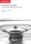
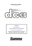
DC5 User’s Manual 1.8.2 Installing the drag knife 1. Remove the aluminum plunger from the plastic knife holder (5) by turning the knurled adjustment knob (3) counterclockwise until the plunger comes out of the holder. 2. Insert the conical, non-cutting end of the knife into the opening in the narrow end of the holder; gently push the knife all the way in. 3. Turn the holder upside down and tap it lightly on a solid surface to ensure that the knife is completely inserted. 4. Slowly turn the knurled knob clockwise until the tip of the blade extends the distance required for the desired cutting media (t) as shown in figure below. FIG 1-26 1-26 KNIFE LENGTH ADJUSTMENT 5. Insert the knife holder into head clamp, seating it firmly. FIG 1-27 1-27 CLAMP DRAG HEAD 6. Close the clamp and tighten the clamp screw. Setup 1-25 2 Basic Operation 2.1 The control Panel The 320x240-dot touch screen provides a unique interface system that provides detailed status information and offers a more flexible and powerful control of the printer’s configuration. All screen and optional panel controls on the touch screen are easily formatted to allow quick access to the most common cutter settings. Next to the status messages and/or menu options displayed on the touch screen, button symbols can be pressed to change menu items or to change the value for a given submenu/parameter. The most used functions are explained in the following paragraphs. It is advised not to touch the control panel while the machine is printing or cutting, except for canceling the current job. Feed Feed Configuration 1 Settings 672mm Media width 75gr Knife pressure 12000 Density Clamp Summa USB port 1 FIG 2-1 2-1 DC5(sx) TOUCH SCREEN There is also screen saving feature. After a certain amount of time the screen goes blank and this logo appears on screen. Touching the screen once disables the screen saver. FIG 2-2 2-2 SCREEN SAVER Basic Operation 2-1 DC5 User’s Manual 2.1.1 Touch screen The touch screen provides information and lets the user change the printer’s parameters. Most common buttons on touch screen: Normally, the status or current value is visible on the left side of the screen, while the control buttons appear on the right side. There are five main control buttons: Settings If a menu is entered, 3 navigation buttons: , , Clamp Home , Configuration 1 More , and Feed Back and Clamp Feed . may appear. Press Home to return to the status screen. If media is loaded in the cutter, then the cutter will come online and be ready to cut a job sent from the computer. Press More for more menu options. If there are more than six options for the chosen menu, then pressing this button will reveal the rest of the options onscreen. Press Back to return one step in the menu structure. Other buttons that will appear on the screen are: , and Numpad arrow buttons to change the values of parameters. Cancel to cancel an instruction or apply a change in current selected parameter. Apply to accept an instruction or a change in current selected parameter. Test to initiate an internal test. Status line: The bottom line gives extra information on the way the printer is connected to the computer. If it is connected through the Ethernet connection, then the IP address is shown. When the printer is online, pressing in the region of the status line is a shortcut to the communication menu. When in menu mode, the status line shows which menu the machine is in. Basic Operation 2-2 DC5 User’s Manual 2.1.2 Settings The Settings button Settings gives access to the main menu. Pressing this button will cause the cutter to go offline and suspend all operations in progress. The main menu contains all parameter settings, submenus and access to tests and calibration routines. The chosen tool will influence the displayed settings. Parameter Settings are recognized by the name of the parameter and the value. Press the parameter to change the value. Density 12000 Sub menus are recognized by the group name followed by three points. Submenus group certain parameters. Access to some of the submenus will be determined by plotting language or tool type. Printer Menu ... Tests & calibrations routines are recognized by the name of the test followed by a small start button. These offer access to the different internal tests and calibration routines. The calibration routines are used to adjust and fine-tune the cutter for the chosen application. The internal tests are used for diagnostics. Calibrate Linefeed 2.1.3 Clamp The clamp button Clamp toggles the status of the clamps. This key works only when the DC5(sx) is in a ready state. The DC5 has three clamps, the DC5sx has two. They both have the left clamp on the rotating base and the pinch rollers. The DC5 has two extra rear clapms. All clamps serve to hold the media in place while printing and transport media forward and backward. The screen prompts the user for a loading procedure when the clamps are raised. 2.1.4 Feed The Feed buttons Feed and Clamp Feed are used for moving the media back and forth. NOTE: Do not move the media unnecessary back and forth. If tracking imprints are made on the backing of the media by moving it first to the front and then back again, then tracking is not any more guaranteed and serious printing quality issues can arise. If a quality check has to be done, then move media first to the rear, then open the front cover and check the quality inside. Basic Operation 2-3 DC5 User’s Manual 2.1.5 Configuration The DC5(sx) printers include 16 user configurations, all of which consist of the same parameters. Each configuration can have unique parameter settings. This allows the printer to be quickly and easily reconfigured for different types of jobs or media. NOTE: A couple of users are pre-configured at the factory. They are configured for the use of the Summa premium vinyls. The rest of the users are all configures the same. NOTE: It is recommended to change the user instead of doing a calibration when changing media type. 1. Press Configuration 1 The first 6 users will appear on screen. 2. Press (once or twice) on when it comes on screen. More to show the rest of the users. Select the desired user 3. Press Apply to confirm the new user. 4. Press Cancel to leave the menu without changing the user. NOTE: Use easy names to quickly recognize what each user is configured to do. NOTE: The touch screen can be used to change user configurations. User configuration names can only be modified through Summa Cutter Control (PC only). NOTE: Some extra predefined users can be found on the DC5 USB stick under the subdirectory ‘users’ send them to the DC5(sx) with Summa Printer Control (see section 6.2.3. NOTE: Be careful these predefined users will overwrite the current user parameters. It is advised to start from 16 down when creating your own. PREMIUM_30_INCH PREMIUM_CLEAR Cancel PREMIUM_24 USER_CONFIG_04 More USER_CONFIG_05 USER_CONFIG_06 Apply Eth 192.168.1.7 FIG 2-3 2-3 USER CONFIGURATION MENU Basic Operation 2-4 DC5 User’s Manual 2.1.6 Serial number and firmware revision Press the DC5 button to check serial number and firmware revision. 2.1.7 Check ribbon status Just above the status line is shown which cassettes/colors are loaded in the machine. It shows also an indication of the amount of ribbon left in the cassette. Press on the button to have more detailed information (color names and a percentage of ribbon left). However know that the amount left is always an estimate. RIBBONS STORE 1: Black : 91% STORE 2: Magenta : 85% STORE 3: Cyan : 48% STORE 4: Yellow : 73% STORE 5: Unknown STORE 6: Unknown STORE 7: Unknown STORE 8: Unknown HEAD : Communication Back Eth 192.168.1.7 FIG 2-4 2-4 DETAILED RIBBON STATUS 2.1.8 Touch screen information while printing Reset PREMIUM 24 Printing: DENSITY Pass 2 out of 3: 33% Printed Time left: 1m 0s Eth 192.168.1.7 FIG 2-5 2-5 TOUCH SCREEN VIEW WHILE PRINTING Following info is available while printing: The name of the current user is shown. The printer also shows the name of the current job, the number of passes that are in the job and an estimate of the time left before the printing is finished. Just above the status line is the information about the loaded cassettes. The outer left position shows which cassette is currently in the carriage. The rest of the loaded cassettes are ordered in the middle of the cassette status line. Basic Operation 2-5 DC5 User’s Manual 2.2 How to Set printing Density Print density refers to the level of energy being sent to the printhead. If the density is too low, the transfer will be incomplete (less than 100%). If the density is too high, the colors will become matted and washed out. Or, the ribbon may start to wrinkle. NOTE: The density setting cannot be used to make the printer darker or lighter Print densities change between different media types because energy is absorbed differently, depending on the vinyl formulation, liner, etc. NOTE: If the hard disk is not installed, then only the monochrome test can be started from the touch screen, use Printer Control for the other tests (section 6.2.5). Setting the print density: 1. Power on the printer and load media (see section 1.6.1). STANDARD DENSITY TEST Old value: 12000 Feed Configuration 1 Feed Cancel Settings 672mm Media width New value: 12000 75gr Knife pressure 12000 Density HIGH RESOLUTION TEST Test Numpad Range: 6000...16000 Apply Clamp Summa USB port 2. Press Density. MONOCHROME DENSITY TEST Printed in OptiTrack color Cancel Eth 192.168.1.7 3. Change value if necessary, 4. Select type of test or press test to check. Cancel. The printer will print the chosen density test. 1 2 FIG 2-6 2-6 INTERNAL DENISTY TEST 3 4 1: If the density is set too high then in area 1 the ribbon will stick too long to the media while printing and leave matt areas behind. 2: If the density is set too low, then this area will not be 100% black (this area is the same color as the rest if the monochrome density test is chosen) 3: If the density is set too high, then this area will be darker than 95% cyan, the white holes will become filled randomly. 4: If the density setting is too low, then these lines will not be printed evenly. NOTE: The density test is optimized for cast vinyl. Other types of vinyl might result in conflicting results, which means that the media is probably less suited for thermal transfer printing. NOTE: If it is impossible to find a correct density setting, then try the high resolution test. If a satisfying result can be reached with this test, then set the parameter double density to ON. 5. Repeat test to check new setting and adjust more if necessary. Basic Operation 2-6 DC5 User’s Manual 2.3 How to Set Media Tracking Parameters The DC5(sx) prints and measures small marks, located at each side of the print, to optimize the tracking performance. After each printing pass, the media is advanced and those small lines are read by a sensor to align the consecutive printed passes. The same sensor is also used to straighten the loaded media in the load direction. NOTE: Each time the media type or the color of the OptiTrac lines is changed, a recommended line feed must be performed (see section below). Failing to do so may result in poor print quality. Choosing OptiTrac color 1. Power on the printer and load media (see section 1.6.1). Feed Configuration 1 Feed Settings 75gr Knife pressure 12000 Density ... Density Cutter menu ... Double Density Home Reprint job 672mm Media width Printer menu Clamp Summa USB port 2. Press Settings. 12000 Off Home Calibrate Linefeed System menu ... Communication ... Shut down Settings 3. Press printer menu. More Back Scratchguard Off OptiTrac color Cyan OptiTrac Automatic More Back Settings | Printer menu 4. Press OptiTrac color. Cyan Magenta Cancel Yellow Black More Red Green Apply Settings | Printer menu 5. Change OptiTrac color by pressing on the color, or press more for rest of colors. Then press Apply. NOTE: Be careful with OptiTrac colors which have a large red component in them, they can usually not be used because the sensor cannot detect them as it reads them as white. It is not recommended to use such colors. NOTE: It is recommended to set OptiTrac to automatic, marks are then always printed on the far right side of the media (there were it is calibrated – see next procedure. NOTE: OptiTrac silver is recommended for printing on dark media. 6. Proceed with line feed calibration (step 0 in next procedure). Basic Operation 2-7 DC5 User’s Manual Line feed calibration 1. Power on the printer and load media (see section 1.6.1). Feed Configuration 1 Media width Feed Settings 75gr 12000 Density ... Cutter menu ... Density Home Reprint job 672mm Knife pressure Printer menu 2. Press Settings. System menu ... Communication ... More Back Settings Summa USB port Off Home Calibrate Linefeed Shut down Clamp Double Density 12000 3. Press printer menu. Scratchguard Off OptiTrac color Cyan OptiTrac Automatic More Back Settings | Printer menu 4. Press Calibrate Linefeed. RECOMENDED LINEFEED SIMPLE LINE FEEDTEST Cancel 5. Press on recommended test. A test pattern is printed and then cut out. Then the DC5(sx) calibrates the OptiTrac sensor and then completes the line feed test. The printed lines are measured and then internal parameters are adjusted automatically. If the DC5(sx) has to compensate too much, it will prompt the operator to redo the test. A simple line feed calibration test will suffice then. LIN E FEED CA LIB RATIO N TES T X X in ch FIG 2-7 2-7 RECOMMENDED LINE FEED CALIBRATION TEST LIN E FEED CA LIB RATIO N TES T X X in ch FIG 2-8 2-8 SIMPLE LINE FEED CALIBRATION TEST Basic Operation 2-8 DC5 User’s Manual Head alignment: The two parameters above control the alignment in the media direction. There is also a calibration in the direction of the movement of the head. This is calibrated mechanically when a head is changed and should not be redone until the head is replaced again. However due to different media parameters (difference in media roll up tension, thickness of media) there might also be need for an extra calibration in the direction of the movement of the head. NOTE: If the hard disk is not installed, then this test has to be started from the program Summa Printer Control. Automatic head alignment setup: 1. Power on the printer and load media (see section 1.6.1). Feed Configuration 1 Feed Settings 75gr Knife pressure 12000 Density ... Cutter menu ... Density Home Reprint job 672mm Media width Printer menu 2. Press Settings. System menu ... Communication ... More Back Settings Home Scratchguard Off OptiTrac color Cyan OptiTrac Automatic More Back Settings | Printer menu 3. Press printer menu. Calibrate Print&Cut Off Calibrate Linefeed Shut down Clamp Summa USB port Double Density 12000 4. Press More. MANUAL TEST Head Alignment Home Clean Printhead Dot Overlap On Color Offset Standard AUTOMATIC TEST More Back Cancel Settings | Printer menu 5. Press Head Alignment. 6. Choose Automatic Test. A test pattern is printed. Some printed lines are measured and then internal parameters are adjusted automatically. If the DC5(sx) has to compensate too much, it will prompt the operator with following text: “VALUE OUT OF RANGE ALIGN HEAD MECHANICALLY”. If so, then a mechanical calibration, as described in the head change procedure, will need to be redone. FIG 2-9 2-9 AUTOMATIC HEAD ALIGNMENT TEST NOTE: Never do a manual head alignment test after an automatic head alignment test, because it defaults the automatic head alignment calibration parameters. Basic Operation 2-9 DC5 User’s Manual 2.4 How to set the main knife parameters: There are two important knife parameters, the offset and the knife pressure. The knife offset is a knife depended parameter. The knife pressure is a media depended parameters. NOTE: Each time the media type is changed, the knife pressure has to be checked each time media type is changed. The knife offset needs to be checked each time the knife is changed. Setting the knife pressure (cutting depth): 1. Power on the printer and load media (see section 1.6.1). 75 Old value: 75 gr Feed Configuration 1 Feed Cancel Settings 672mm Media width Knife pressure New value: 75 gr 75gr Numpad 12000 Density Range: 0 ... 400 gr Clamp Summa Eth 192.168.1.7 USB port 2. Press on pressure Test Settings Apply Apply Eth 192.168.1.7 Eth 192.168.1.7 3. Press arrow up or down to 4. Or fill in the new value change the value. after pressing Numpad. 1. Press Test to perform the internal knife pressure test. 2. Press Apply to confirm the chosen knife pressure and exit the menu. 3. Press Cancel to leave the pressure unchanged. Once Test is pressed, the current knife pressure value will be set automatically to the new value and the cutter will cut the knife pressure test pattern. FIG 2-10 2-10 KNIFE PRESSURE TEST PATTERN Peel out the rectangle and inspect the backing. The knife depth is set correctly when the test pattern cuts through the vinyl completely, the vinyl is removed, and the blade tip visibly scratched the front side of the media backing. The blade should never cut through the backing; just slightly scratch the silicon coating and first few fibers of the backing material. Basic Operation 2-10 DC5 User’s Manual Setting the knife offset: 1. Power on the printer and load media (see section 1.6.1). Feed Configuration 1 Feed Settings 75gr Knife pressure 12000 Density ... Cutter menu ... ... Communication ... Shut down Clamp Summa USB port 2. Press Settings. System menu 75 gr Knife pressure Home Reprint job 672mm Media width Printer menu More Back Settings 0.43 mm Knife offset Velocity 500 mm/s Overcut 0.2 mm FlexCut ... Calbrate Print&Cut Home More Back Settings | Cutter menu 3. Press cutter menu. 4. Press Knife offset. 0.43 Old value: 0.45 mm Cancel New value: 0.43 mm Numpad Test Range: 0.00 ... 1.00 mm Apply Apply Settings | Cutter menu Settings | Cutter menu Eth 192.168.1.7 5. Use arrows to change knife 6. Or fill in the new value after offset. pressing Numpad. 1. Press Test to perform the internal knife offset test. 2. Press Apply to confirm the chosen knife offset and exit the menu. 3. Press Cancel to leave the knife offset unchanged. When the knife offset is set correctly, the test pattern looks like this: FIG 2-11 2-12 CORRECT KNIFE OFFSET PATTERN When the knife offset is too low, the test pattern looks like this: When the knife offset is too high, the test pattern looks like this: Change the knife offset value if the cut out pattern is not correct. Basic Operation 2-11 DC5 User’s Manual 2.5 How to calibrate print and Cut The print head and the cutting head have each their own origin point. Perform the following test to align the both origins so that the contour cuts are not offset. NOTE: Each time the knife is replaced or media type is changed, then the print and cut calibration has to be done. Only do a print and cut calibration if the media tracking and knife parameters are set correct (see section 2.3 and 2.4). NOTE: If the hard disk is not installed, then this test has to be started from the program Summa Printer Control. Print and cut calibration: 1. Power on the printer and load media (see section 1.6.1). Feed Configuration 1 Feed Settings 75gr Knife pressure 12000 Density ... Cutter menu ... 2. Press Settings. System menu ... Communication ... More Off OptiTrac color Cyan Automatic More Back Settings | Printer menu 4. Press More. SET 1 SET 2 SET 3 SET 4 SET 5 SET 6 SET 7 0 0 0 0 0 0 0 Home Scratchguard OptiTrac Back 3. Press printer menu. Head Alignment Home Calibrate Linefeed Settings Calibrate Print&Cut Off Double Density Home Shut down Clamp Summa USB port 12000 Density Reprint job 672mm Media width Printer menu Clean Printhead Dot Overlap On Color Offset Standard More Back Apply Settings | Printer menu 5. Press Calibrate Print&Cut. 6. Set values correct and press Apply. The DC5(sx) first prints and cuts out a test pattern similar to the one below. SET 1 SET 2 SET 3 SET 4 SET 5 SET 6 SET 7 -8 +8 -8 +8 -8 +8 -8 +8 -8 +8 -8 +8 -8 +8 -7 +7 -7 +7 -7 +7 -7 +7 -7 +7 -7 +7 -7 +7 -6 +6 -6 +6 -6 +6 -6 +6 -6 +6 -6 +6 -6 +6 -5 +5 -5 +5 -5 +5 -5 +5 -5 +5 -5 +5 -5 +5 -4 +4 -4 +4 -4 +4 -4 +4 -4 +4 -4 +4 -4 +4 -3 +3 -3 +3 -3 +3 -3 +3 -3 +3 -3 +3 -3 +3 -2 +2 -2 +2 -2 +2 -2 +2 -2 +2 -2 +2 -2 +2 -1 +1 -1 +1 -1 +1 -1 +1 -1 +1 -1 +1 -1 +1 0 0 0 0 0 0 0 0 0 0 0 0 0 0 FIG 2-11 2-13 PRINT AND CUT TEST PATTERN Check for the squares where the cut line is just above the printed line; use those values to insert via the control panel. If the values were too far off, then redo the test. Basic Operation 2-12 DC5 User’s Manual 2.6 How to Change media width 2.6.1 Pinch roller positioning. The DC5 has 6 positions for the right pinch roller: 50, 61, 76, 100, 120 and137cm (19, 24, 30, 40, 48 and 54 inch). The DC5sx has 3 positions for the right pinch roller: 50, 61 and 76cm (19, 24 and 30 inch). The line feed calibration (see section 2.3) depends on the loaded media width. The line feed parameters are stored per user. So either the line feed calibration has to be redone when media width is changed or the user will have to switch to a pre-configured user with the correct media width. It is recommended to calibrate certain users for specifics widths of vinyl and to change user when media width is changed. Not changing user when changing media width will finally result in wrongly calibrated users and bad print quality. When calibrating a certain user for a specific width, then do the print and cut calibration (see section 2.5) right after the line feed calibration. This calibration is also depended of the loaded media width. 2.6.2 Using oversized media widths. It is recommended to use only recommended media widths listed in the specifications. Oversized media can be loaded, but these materials will not perform within the regular Summa specifications of tracking and accuracy. When a user is calibrated for a certain media, then a line feed calibration test is done. When the job sets the OptiTrac marks on the same place as the line feed calibration test, then the resulting job is at its accurate. Therefore it is recommended to use ‘automatic’ as value for the OptiTrac parameter. But when oversized media is used then the OptiTrac marks are printed outside the pinch rollers, then the accuracy quickly drops. Basic Operation 2-13 DC5 User’s Manual 2.7 Preparing the DC5(sx) for long print-outs The DC5(sx) has a fixed position at the rear for the roller guiding of the flange. It is possible that some types of vinyls are not wound up even (e.g. the core sticking out). This results in a forcing of the path of the vinyl in a wrong direction. Following procedure can help to solve that problem: 1. Load media in the machine as described in section 1.6.1. 2. Print out a small test of 2 or 3 band-passes high. FIG 2-12 2-14 REPOSITIONING ROLLER GUIDE 3. Check the path of the media. The distances, marked with the white arrows and the same number, should all be the same. The middle arrow of the second photo points to the roll itself 4. If not, check first if the media has moved from its place of origin. If so reload with a maximum loop at the back. 5. If it did not move, then reposition the rollerguide, so that the path of the vinyl is as shown above. Make also sure that the flange is flush to the core. Basic Operation 2-14 3 Print & Cut 3.1 Contour cutting There are two possible ways to contour-cut . Normally the cutting is done automatically direct after the job is printed. The Rip recognizes the contour lines splits up print and cut data, sends first the printing data to the DC5(sx) and then the cutting data. When the printout has to laminates, then extra registration marks have to added so the job can then be cut afterwards. NOTE: The DC5(sx) can print a protective layer (with the scratch guard ribbon) so most lamination jobs can done while cutting and can then be cut immediately after printing. In case the printouts are used in a harsh chemical, abrasive or climatologic environment, then extra lamination is necessary ( section 3.1.1.2). 3.1.1 Making the design The orientation shown in this figures is as it will be seen on the computer screen when the design is created. When the design is exported and printed out with SCC, then orientation on the printer is rotated by 180%. Create the design and contour line. For easier handling, place the contour lines on a different layer (they will have to be cut out afterwards). Contour line FIG 3-1 3-1 DESIGN WITH CONTOUR NOTE: When defining contours, do not define them exactly on the border of the design! It is advised to leave either a white space between the contour and the design, or to define the contour inside a thick outline. Or better jet, just inside the design. If the contour is designed right on the edge of the drawing, then the slightest misalignment will result in a bad result. Print&Cut 3-1 DC5 User’s Manual Contourline Contourline Recommended Contourline Contourline FIG 3-2 3-2 ADVISED PLACES FOR CONTOUR PLACEMENT 3.1.1.1 Contour cutting Define the line that needs to be cut as a special color that the RIP recognizes as an object to be cut. NOTE: When using Summa Color Control (see section 6.3) it is advised to use the spot color palette and the spot color CONTOUR. Summa Color control print then first the other objects and afterwards the objects which have as color CONTOUR will be cut automatically. Send the job with the RIP to the DC5(sx) 3.1.1.2 OPOS cutting NOTE: The DC5(sx) cannot be used as a contour cutter. It is even advised not to use it as a cutter (see section 6.1.4) . When the printed job has to laminated before cutting then extra registration marks have to be printed. This section explains how to set the marks so the design can be cut after lamination with a Summa Cutter. There exists a plug-in for CorelDraw and Adobe Illustrator to set the marks automatically around a design (see section 6.1.2).Otherwise use follow procedure below to set the marks. Put the OPOS marks around the drawing. In your design the top right corner is the origin of the design that will be printed out. Place the origin mark at the right side and above all contours that need to be cut. Print&Cut 3-2 DC5 User’s Manual X-size Y-size FIG 3-3 3-3 PLACEMENT OF THE FIRST (ORIGIN) MARK NOTE: The mark must be a square. The advised size is 3mm and the line style of the mark is best set to none (line styles with a certain thickness affect the precision). NOTE: Make sure that around every mark a ‘white space’ which is 3-4 times the size of the mark. Place rest of the marks. X-distance Y-distance FIG 3-4 3-4 PLACEMENT OF THE REST OF THE MARKS First place copies of the origin mark at a regular distance in the up/down direction. The last mark at the bottom must be under all contours that need be cut. This direction will be referred to as the X-direction. NOTE: Make sure there is enough white space around every mark. The distance between the different marks must be the same. NOTE: The advised X-distance (distance between two consecutive marks) depends on several items. Normally 30 to 40 cm is a recommended distance. If the mark size is smaller than 3mm, lower the X-distance. If the white margin is critical, lower the X-distance. The bigger the distance between the marks, the faster the registration of the marks works. The smaller the distance between the marks, the more accurate OPOS works, however the influence on the accuracy is rather small. Print&Cut 3-3 DC5 User’s Manual Make a copy of the row of marks and place them left to the design. NOTE: Make sure the left row is not shifted in the up/down direction in reference to the right row of marks. Make the layer on which the contour lines are invisible and not printable. Print the design together with marks on the DC5(sx). NOTE: Make sure not to scale or rotate the design in the RIP. NOTE: It is advised to group the jobs on a roll, since with each sheet there needs to be rear margin of 8cm. (see user manual for the Summa cutters for exact values according to type and model). FIG 3-5 3-5 PRINTED DESIGN Print&Cut 3-4 DC5 User’s Manual 3.1.1.3 Making cutting data ready Make the layer on which the contour lines are visible and printable. Do the opposite with the print data. Make sure that he origin mark (top right) is also defined as a contour. This will be used as the origin for the cutting. It is recommended to use WinPlot for sending cutting data to the DC5(sx). WinPlot also send the OPOS parameters automatically to the DC5(sx). Just click on the OPOS cut icon and the parameters will be send to the cutter and the special load will be activated (the machine will ask the user to put the knife tip above the first OPOS mark. When using WinPlot, then the orientation of the design loaded in the Summa cutter must be the same as the orientation on screen in WinPlot. Complete design Cutting data FIG 3-6 3-6 SELECTING CUT DATA Print&Cut 3-5 DC5 User’s Manual 3.2 Cutting trough The cutting through functionality is focussed to cut simple shapes (e.g. rectangles). It is most used in combination with contour cutting. An interrupted cutting line makes sure that the material remains together thanks to the small media ‘bridges’. When the job is finished the cut pieces can be torn loose. FIG 3-7 3-7 FLEXCUT PRINCIPLE Some software can recognize the difference between a contour line and a cut-through line. The software sends then first the data of the contour lines to the cutter, and then it activates FlexCut, panelling mode and vector sorting and sends the data for cutting through to the cutter. NOTE: If the software cannot recognize the difference between the two types of cut line, then it is not recommended to use this feature. Setting the parameters for cutting through the media: 1. Power on the printer and load media (see section 1.6.1). Feed Configuration 1 Media width Knife pressure Density Feed Settings 75gr 12000 2. Press on Settings. Flex pressure Flex pressure cut length Cutter menu ... System menu ... Communication ... Shut down Clamp Full pressure cut length ... Knife pressure Home Reprint job 672mm More Back Settings Summa USB port Full pressure Printer menu 3. Press on Cutter menu. Knife offset 75 gr 0.43 mm Velocity 500 mm/s Overcut 0.2mm FlexCut ... Calibrate Print&Cut Home More Back Settings | Cutter menu 4. Press on FlexCut. 180 gr 7.500 mm Home 80gr 0.750 mm Back Settings | Cutter menu | FlexCut 5. Select parameter to change. Print&Cut 3-6 DC5 User’s Manual Old value: 180 0.45gr mm Cancel New value: 180 0.43gr mm Numpad Test Range: 0 0.00 ... 400 ... 1.00 gr mm Press arrows or use Numpad to change the Full pressure and press Apply to confirm. 180 gr is a recommended starting value for the full (cut through) pressure. Press arrows or use Numpad to change the Full pressure cut length and press Apply to confirm. 10 mm is a recommended starting value for the cutting length at full pressure. Press arrows or use Numpad to change the Flex pressure and press Apply to confirm. 50% of the full pressure is a recommended starting value for the flex (bridge) pressure. Press arrows or use Numpad to change the Flex pressure cut length and press Test to confirm and cut out test. 1mm is a recommended starting value for the cutting length at flex pressure. Apply Settings | Cutter menu | FlexCut Old value: 7.500 0.45 mm mm Cancel New value: 7.500mm 0.43 mm Numpad Test Range: 0.250 0.00 ......1.00 250.000 mm Apply Settings | Cutter menu | FlexCut Old value: 80 0.45grmm Cancel New value: 80 0.43grmm Numpad Test Range: 0 0.00 ... 200 ... 1.00 gr mm Apply Settings | Cutter menu | FlexCut Old value: 0.750 mm 0.45 mm Cancel New value: 0.750 mm 0.43 mm Test Numpad Range: 0.250 250.000 0.00 ......1.00 mm Apply Settings | Cutter menu | FlexCut The cutter will cut out a test pattern. 6. Check if the result is the satisfactory. If not change one of the 4 parameters above. Reducing the velocity can also improve the result. It is never recommended to use cutting speeds larger than 400mm/s (16 ips) with cutting pressures above 200 gr. NOTE: It is not always easy to find the correct balance between cutting deep enough making sure the pieces can be taken out easily, and not cutting too deep making sure the material keeps it strength while cutting. Sometimes this balance doesn’t exist meaning that this material can’t be cut through with satisfactory result. NOTE: When cutting through, it is recommended that parallel lines are at least 1 cm away from each other. Otherwise, while cutting the second line, the first line may come loose and cause trouble. NOTE: FlexCut parameters are always metric, regardless the value of the panel Units parameter. 7. After that press Print&Cut Back and then press Home . 3-7 4 Detailed Operation 4.1 Introduction This section is a detailed list of all parameters that can be changed and tests that can be initiated from the touch screen. Section 1 and 2 of this manual describe in detail the most commonly used touch screen manipulation. This section may be used as a reference for locating a certain parameter setting or test. The less frequently used parameters are also explained in this section. Detailed Operation 4-1 DC5 User’s Manual Settings ... Printer Menu 12000 Density Off Scratchguard Calibrate Print&Cut Double Density OptiTrac Color Off Cyan Head Alignment Dot Overlap Calibrate Linefeed OptiTrac Automatic Clean Printhead On Color Offset Standard 75gr Knife offset 0.43 mm ... Cutter Menu Knife pressure 0.2 mm OverCut ... FlexCut Velocity 500 mm/s Calibrate Print&Cut DIN A4 test Reprint Job ... System Menu Print Only Job Take Up Roll Calibrate touch screen Metric Menu units Ribbon Save Standard LCD contrast 255 Copy user settings Calibrate media Calibrate OPOS Coil setup Configure Status Calibrate NTC ... Communication On DHCP USB Class Summa USB port 1 Shut Down More Reset FIG 4-1 4-1 COMPLETE MENU STRUCTURE Detailed Operation 4-2 DC5 User’s Manual 4.2 Printer Menu This menu bundles all the printer settings of the DC5(sx). All settings in this section are userdependent (information is contained within each of the sixteen individual user settings, see section 2.1.4.). 4.2.1 Density This is the first parameter that has to be set if a new type of media is loaded in the printer, all calibrations and settings of any other parameter is not usable; if this parameter is not set correct first. The setting of this parameter is explained in section 2.2. 4.2.2 Double density Double density is a special printing mode. This mode enables the DC5(sx) to print on a much wider range of materials. Press the Double Density button, then set it off or on. Press Apply to confirm or Cancel to cancel. 4.2.3 Calibrate linefeed The calibrate linefeed test is used to calibrate the media feed. It is advised to do this test each time a vinyl roll is changed. This test is fully automatic. It is explained in section 2.3. 4.2.4 Scratchguard The option Scratchguard makes it possible to put a layer of protective coating on the printed images. Press the Scratchguard button, then set it off or on. Press Apply to confirm or Cancel to cancel. 4.2.5 OptiTrac color The DC5(sx) prints and measures small lines, located at each side of the print, to optimize the tracking performance. The color of these lines can be changed within this menu. Be sure to use colors that are in contrast with the vinyl color. The menu option to change color is useful when printing monochrome, or on colored vinyl. The default value for white vinyl is cyan. If white, gold or silver is chosen as OptiTrac color, then the DC5(sx) will raise the head between the left and right OptiTrac mark if the color is not used automatically without the need to set ribbon save high. Changing OptiTrac color is explained in section 2.3). Detailed Operation 4-3 DC5 User’s Manual 4.2.6 OptiTrac This menu allows setting the OptiTrac™ feature to automatic, ON, OFF, white background or full white. The default setting is automatic, which means the OptiTrac™ lines are printed on the outer left and right side of the media. This gives the most accurate tracking performance because the OptiTrac marks are printed on the same place where the line feed calibration test was done.. If this parameter is set to on, then the OptiTrac marks are printed as close to the design as possible, this saves ribbon, but could be compromising on accuracy. OFF is used for special media on which the marks cannot be read. This means that the line feed has to be done manually and that there will always be a relative large overlap. White background and full white are used for reflective media or media with reflective particles. The media calibration test (see section 4.5.6) test can be used to determine which setting can be used. The procedure to set this parameter is explained in section 2.3. 4.2.7 Calibrate Print&Cut This test cannot be started from the touch screen if no hard disk is installed, the DC5(sx) will prompt the user to start the test from the program Summa Printer Control. The Calibrate Print&Cut calibration is explained in section 2.5. 4.2.8 Head Alignment There are two head alignments one manual and one automatic. The manual one should only be done if a head is changed or if there is a mechanical mis-alignment, the automatic on should be used in all other cases. This test cannot be started from the touch screen if no hard disk is installed, the DC5(sx) will prompt the user to start the test from the program Summa Printer Control. The manual head alignment test is used to check if the carriage is aligned (mounted) correctly on the DC5(sx). This test should only be performed after a head or a carriage change. Fig 4-4 shows the pattern that is printed using this test. The lines must meet, in the middle, within a certain tolerance. Please refer to document enclosed with spare head for more detailed info. The automatic test sets a user parameter, this means that this value is different for every user configuration and is explained in section 2.3.). FIG 4-2 4-2 HEAD ALIGNMENT TEST Detailed Operation 4-4 DC5 User’s Manual 4.2.9 Clean printhead This routine cleans the printhead. If the transfer of the ribbon has degraded, then this cleaning procedure will clean the printhead automatically. Also, the printhead is periodically cleaned while printing. Do not use this cleaning routine too often as it can prematurely wear down the printhead surface. This procedure cleans any build-up from the heat resistant layer, which is coated on the backside of the ribbon. Press the Clean head button to start the cleaning procedure. 4.2.10 Dot Overlap The dot overlap paramter is used to activate or deactivate the dot overlap. When the DC5(sx) prints the next pass of an image, the last dot on the edge of the previous pass is reprinted. Dot overlap can be set to on, half or off. It is advised to set dot overlap to ON. When printing with a mask (see 6.3.6), set it to HALF. If this parameter is set to off, then small gaps between printing bands may appear. Press the dot overlap button, then set it off, half or on. Press Apply to confirm or Cancel to cancel. 4.2.11 Color offset The color offset sub-menu is used to set the color offset feature. While printing, the DC5(sx) shifts each color plane 8 dots (standard). This is to blend the printed strips together more gradually. The figure below shows how offset color plane strips are printed. Color offset can be increased (16 dots: high) or disabled (0 dots: disabled). It is advised to set color offset to standard. Press the dot Color offset button, then set it off, half or on. Press Apply to confirm or Cancel to cancel. FIG 4-3 4-3 COLOR OFFSET Detailed Operation 4-5 DC5 User’s Manual 4.3 Cutter menu This menu bundles all the cutter settings of the DC5(sx). All settings in this section are userdependent (information is contained within each of the sixteen individual user settings, see section 2.1.4.). 4.3.1 Knife pressure The knife pressure submenu is used to change the default knife pressure (same as in section 2.4, but it can be changed when no media is loaded, however it can’t be tested). The knife pressure can be set between 0 and 400 grams. Press the Knife pressure button, then change the knife pressure to the desired knife pressure. Press Apply to confirm or Cancel to cancel. 4.3.2 Knife offset The knife offset is explained in section 2.4. 4.3.3 Velocity The Velocity submenu is used to change the default velocity for the knife. The velocity can be set between 50 mm/s (2 ips) and 600 mm/s (24 ips). The default velocity is 500 mm/s (20 ips). Press the Velocity button, then press on the desired velocity to change the velocity, use arrow up/down if the desired velocity is not on screen. Press Apply to confirm or Cancel to cancel. 4.3.4 Overcut Use overcut submenu to generate an overcut in order to facilitate weeding the cut. Each time the knife goes up or down, the cutter cuts a bit further then it should. The overcut setting can be disabled (=0) or set to any value between 0 and 1mm in increments of 0.1mm. Press the overcut button and change to the desired value. Press Apply to confirm or Detailed Operation Cancel to cancel. 4-6 DC5 User’s Manual 4.3.5 FlexCut The FlexCut submenu is explained in section 3.2, however setting up the DC5(sx) for FlexCutting is not that easy. Follow next procedure to try and determine usable FlexCut settings. 1. Turn out the knife so that the out coming knife tip is longer than the material thickness. NOTE: Never turn the knife so far out, that the media can hit the knife shaft. Only the knife edge may get in contact with the media in order to avoid media crashes. 2. Go to the knife pressure submenu (see section 2.4). Increase the knife pressure gradually and do in between the knife pressure test. Until the minimum knife pressure to cut the material completely through is reached. Then increase this value with 5-10%. Write this value down. NOTE: It is discouraged to use brand new knives for cutting through. Pressure setting and knife depth of brand new knives change quickly. NOTE: It is recommended to use cutting speeds of 300mm/s (12 ips) and lower when cutting pressures is 200 gr or higher. 3. Turn the top piece of the knife holder a half turn counter clockwise. In the ‘knife pressure’ menu, press the test to activate the knife-pressure-test-pattern. If the pattern is still cut out completely, repeat these actions. Once the pattern is not cut anymore, increase the knife depth (turning clockwise) with 1/8’s of a turn, and perform the test, until the minimum required knife depth is reached. Now increase (clockwise) the knife depth slightly ( ½ of a turn). 4. Now decrease the knife pressure gradually and do in between the knife depth test until the knife pressure is set as described in section 2.4. Also write down this value. 5. Go to the flex cut sub menu and set full pressure to the pressure that was needed to cut through the media and set flex pressure to the normal pressure. Set the full pressure length to 10mm and the flex pressure length to 1mm. Then cut a test pattern. Depending on the strength (size) of the ‘bridges’ go to step 6 or 7. 6. If the bridges are too strong, then decrease the flex pressure length and do the test again. 7. If the bridges are too weak, increase the flex pressure length and do the test again. NOTE: Keep the flex pressure length between 0.5 and 1.5mm. If no good setting can be found, then try with changing the flex pressure itself (lower if bridges are too strong, raise if they are too weak). Detailed Operation 4-7 DC5 User’s Manual 4.3.6 Calibrate Print&Cut This test cannot be started from the touch screen if no hard disk is installed, the DC5(sx) will prompt the user to start the test from the program Summa Printer Control. The Calibrate Print&Cut calibration is explained in section 2.5. 4.3.7 DIN A4 test This test cannot be started from the touch screen if no hard disk is installed, the DC5(sx) will prompt the user to start the test from the program Summa Printer Control. The DIN A4 Test also performs an electrical and mechanical test of the cutter part of the DC5(sx), in order to check the cut quality, but also provides the user with feedback on knife setting, knife pressure, knife offset, and cutting depth. 4.4 Reprint job This menu is only accessible if the hard disk option is installed. The DC5(sx) then stores every sent job on hard disk. If the hard disk is almost full, the oldest jobs will be deleted automatically without any warning. REPRINT File name Apply SUMMALOGO Number of copies Cancel 1 delete all FIG 4-4 4-4 REPRINT MENU Press the reprint job button. Use the top print jobs. Use the bottom Press Apply and to start printing. Use the Detailed Operation and arrows to scroll through the saved arrows to change the number of copies. delete all button to delete all files on the hard disk. 4-8 DC5 User’s Manual 4.5 System menu This menu bundles the less frequent used parameters and calibrations. Only the parameter take up roll and ribbon save are user dependent parameters. 4.5.1 Take-up roll The take-up roll sub-menu is used to activate or deactivate the take-up rollers (optional on DC5sx). This option can be set to disabled, print job only and print and cut job. Press the take up roll button and select the desired setting. Press Apply to confirm or Cancel to cancel. 4.5.2 Ribbon save The ribbon save sub-menu is used to set the ribbon save mode. In standard mode, a ribbon is used over the full width of the print job as soon as one dot is required in the print pass. No ribbon will be used if no data in that ribbon color is required in the print pass. In ribbon save mode high, no ribbon will be used if no data in that ribbon color is required in the print pass and ribbon will also be saved as soon as no data in that ribbon color is required anymore on the right-hand side of the image. The default setting is standard. NOTE: With ribbon save mode high, the printhead is raised inside the image. This may leave an impression in the vinyl causing print quality issues in the next print passes. Press the ribbon save button and change setting is necessary. Press Apply to confirm or Cancel to cancel. 4.5.3 Copy User settings This menu enables the operator to copy the parameters from one user to another user. When copying the parameters, the user name is not changed. These parameters can then be used as starting values for configuring a new user. Press the copy user button. COPY USER FROM Apply PREMIUM 30 TO Cancel PREMIUM CLEAR FIG 4-5 4-5 USER CONFIGURATION MENU Use the top and arrows to scroll through the users from which parameters will be copied. Use the bottom and arrows to select the destination user. Press Apply to confirm. The user configurations are setup to quickly change several parameters depending on the type of vinyl or kind of job Detailed Operation 4-9 DC5 User’s Manual 4.5.4 Calibrate touch screen This option makes it possible to calibrate the touch screen. Perform this calibration if the illustration of the button on the touch screen does not match the area that needs to be pressed to activate the button. Press button to start the calibration and follow guidelines on screen. Press the crosses with a pen Xlow:42 Xhigh:233 Ylow:44 Yhigh:234 Press the crosses with a pen Apply FIG 4-6 6 BEFORE CALIBRATE TOUCH SCREEN FIG 4-7 7 AFTER CALIBRATING TOUCH SCREEN 4.5.5 LCD contrast The LCD contrast submenu is used to adjust the contrast (or intensity) of the touch screen. The firmware automatically rejects values that would make the touch screen too dark to be able to use it. Press the LCD contrast button, then set to the desired value. Press Apply to confirm or Cancel to cancel. 4.5.6 Calibrate media Calibrate media is used to optimize the parameters of the OptiTrac sensor. Press the calibrate media button to perform the calibration. The DC5(sx) prints out the pattern below. The calibration is automatic. Some values are shown on the touch screen while the machine is calibrating, they can be useful for a service technician. FIG 4-8 4-8 CALIBRATE MEDIA TEST 4.5.7 Menu Units The setting of these options determines whether the speed and size values are displayed in the metric measure system or ENG/US measure system. Press the Menu units button, then set to the desired measure system. Press Apply to confirm or Detailed Operation Cancel to cancel. 4-10 DC5 User’s Manual 4.5.8 OPOS Calibration NOTE: This test is obsolete not to be used with current firmware revisions. This calibrates the physical distance between the mark sensor and the knife tip. Press the OPOS calibration button to start the test. The DC5(sx) will cut out three rectangles. After that the machine will prompt the user to weed the three rectangles. Do so and press continue Back . The DC5(sx) will now measure the difference of the reflection level of the backing and the media. Then it will search the edges of the two outer rectangles. If the vinyl is not appropriate for the test, then the DC5(sx) will give a message. Then the test has to redone with a vinyl which has a high contrast between the media and the backing color (or white media with clear backing). 4.5.9 Coil setup This test is used to set the knife “landing.” The cut quality is seriously affected by incorrect landing setting. Before changing these values, write them down, as there is no default setting for these parameter. After adjustment, the value is saved automatically when the sub menu is exited. The landing determines, among other things, the force at which the tool hits the media. When calibrating the landing, the tool holder with the knife must be inserted in the head. Be sure that the knife does not protrude. Use to lower the landing value until the tool is in the “up” position. Then use to raise the value of the parameter. With each unit of change, continue checking if the tool is completely down yet. Once the tool is completely down, raise the value five units, and this becomes the proper setting. Press Apply to leave the menu. 4.5.10 Calibrate NTC This test is used when a printhead is changed. This test is fully automatic. The machine needs to be rebooted after the test. NOTE: Do not calibrate NTC’s unless instructed by a certified technician. Wait at least half an hour after the last printed job before performing a calibration (head needs to be cooled down to room temperature for correct result). Detailed Operation 4-11 DC5 User’s Manual 4.6 Communication 4.6.1 DHCP DHCP can be set to on or off, it is recommended to work with a fixed IP address (DHCP off). Section 1.5.2 explains how to set this parameter. 4.6.2 Configure This sub menu is used to set the IP address parameters. Section 1.5.2 explains how 4.6.3 Status This sub menu gives an overview of the IP address settings, whether they are set manually or filled in by the DHCP server. It also shows the MAC address of the Ethernet connection. 4.6.4 USB Class USB class can be set to Summa USB port 1, Summa USB port 2, Summa USB port 3 or Summa USB port 4. Because of the different USB id’s, the computer can make a distinction between several printers attached to it (maximum 4). Press the USB Class button, then set to the desired USB Class. Press Apply to confirm or Cancel to cancel. The default mode is Summa USB port 1. NOTE: The USB id in the printing software has to be the same as the chosen USB id in the DC5(sx). Each time a new USB is select on the printer and connected for the first time to the computer, the wizard for installing a driver will be started by Windows. 4.7 Shut down…. After pressing the shot down button, the DC5(sx) removes any cassette from the carriage, closes any open files on the hard disk and raises the pinch rollers. It is advised to use this key when shutting down the DC5(sx), especially for minimizing wear on the pinch rollers. If the pinch rollers are left down for a long period of time, a flat spot is created on the wheel and tracking becomes a problem and is not guaranteed any more. The pinch rollers are automatically raised when the DC5(sx) is idle for more than 4 minutes. 4.8 Reset When pressing the reset button, the DC5(sx) will reset. This reset is not a full reset. To completely reset the machine, perform a cold reset (switch off and on the power to the machine). Detailed Operation 4-12 5 Maintenance and Cleaning 5.1 General information The DC5(sx) has a number of sliding surfaces made of smooth metals and plastics. They are virtually friction-free and require no lubrication. They will, however, collect dust and lint, which may affect the performance of the DC5(sx). Keep the DC5(sx) as clean as possible by keeping the front cover always closed. When necessary, clean the unit with a soft cloth dampened with isopropyl alcohol or mild detergent. Do not use abrasive cleaners. WARNING: The printing surface is made out of a special cellular material. Do not touch it! Cleaning it with any kind of fluid will permanently damage it. Also if pressure is applied to the surface with anything other than the printhead, the printing surface could also be permanently damaged. 5.1.1 Cleaning the drive system After time and usage, the sleeves of the drive drum may become clogged with accumulated residue from the media liner. This situation may affect traction, as the media will tend to slip between the pinch rollers and the drive sleeves. 1. Unplug the power cord. 2. Apply a mild solvent (normally used to remove old glue residue) on the yellow sleeves and wait for it to dissolve the accumulated residue. 3. Clean with a brush (toothbrush is recommended) 4. Repeat for all dirty drive sleeves. 5.1.2 Cleaning the media sensors After a time and usage, the sensor may become dirty with accumulated residue from the media. This situation may cause malfunctioning of the DC5(sx). 1. The front sensor is located on the DC5(sx) left side, right next to the pinch roller. The rear sensor is located on the same line as the front sensor but on the rear plate. 2. To keep the sensors clean, it is sufficient to wipe them out with a cotton swab. FIG 5-1 5-1 POSITION FRONT SENSOR Maintenance FIG 5-2 5-2 POSITION REAR SENSOR 5-1 DC5 User’s Manual 5.1.3 Changing he cleaning pad Located on the left side of the DC5(sx) is a printhead cleaning pad. The printer cleans the head periodically on this pad. It is possible that after a while some dust will accumulate on this pad. Therefore it is advised to clean this pad from time to time. To clean the cleaning pad, proceed as follows: 1. Take a piece of scrap vinyl that is a bit larger than the cleaning pad. Remove the backing and stick it on the cleaning pad. 2. Gently apply equal pressure on the vinyl, pressing the adhesive on the pad. 3. Remove the vinyl and check the back of the vinyl. If it is dirty do the procedure again, until the vinyl does not show dirt from the cleaning pad. If the cleaning pad starts turning white, it is worn out and should be replaced. Cleaning pad notes: The cleaning plate should be cleaned every week or after each change of roll vinyl which ever come first. Every five rolls of vinyl, the cleaning pad should be replaced (or turned once – mark used side so it is not used twice). Using not approved material can raise the need to perform these actions. Cleaning pad should be changed if the printhead is changed. FIG 5-3 5-3 CLEANING PAD Maintenance 5-2 DC5 User’s Manual 5.1.4 Cleaning the printhead The printhead accumulates dust, debris and resin residue, which can all degrade the print quality. The printer will automatically self-clean the printhead (see section 0). While this procedure removes much of the residue and debris, the printhead will sometimes require manual cleaning, particularly after a ribbon breakage because large pieces of ribbon material might be caught underneath the carriage. Do not clean the printhead just after printing. The printhead is still hot after printing. Touching it too soon after printing might cause injuries. Do not clean the printhead above the printing surface. To clean the printhead, proceed as follows: 1. Power off the DC5(sx). Open up the rear cover and take out the cassette. 2. Use a lint free cloth, or gauze, moistened with isopropyl alcohol. 3. Gently wipe the printhead (1), the release plate (2) and the rollers (4). 4. Note the position of the ribbon end sensor (3). Note: Clean the printhead after every each ribbon problem (extensive wrinkling or breaking of ribbon. FIG 5-4 5-4 CLEANING THE PRINTHEAD 5.1.5 OptiPrint™ cleaning system The maintenance of the system is described in the installation guide which was packed separate in the accessory box. Maintenance 5-3 DC5 User’s Manual 5.1.6 Cleaning the printing surface The printing surface is very delicate. It is made out of cellular material. Oil and moisture from fingers damages the surface, therefore great care should be taken when the printing surface is uncovered. DO NOT TOUCH SURFACE. In rare cases it might be necessary to clean the printing surface. It is not recommended to do it, but sometimes it is the only safe way to remove dirt. To clean the printing surface, proceed as follows: 1. Power off the DC5(sx) and remove the vinyl. 2. Cut a piece of vinyl, the size of the printing surface width is 14cm, length is machine dependent) and stick it onto the printing surface. 3. Power on the DC5(sx) and load the media. Print out a rectangle full width and height, consisting out of two colors app 20% coverage. 4. Remove the media from the DC5(sx) and turn off the power. 5. Carefully remove the vinyl from the printing surface. This test has been done with 3M cast white vinyl. Do not attempt to use any other vinyl to clean the printing surface. The reaction of the adhesive on the printing surface might damage it. Do not leave the vinyl on the printing surface longer than is necessary for this test. Maintenance 5-4 DC5 User’s Manual 5.2 Operating voltage WARNING: Before changing the fuse, make sure that the cutter is completely disconnected from its power source. WARNING: : For continued protection against risk of fire, replace only with the same type and rating of fuse: T4.0A, 250V SCHURTER SPT OR EQUIVALENT. 1. To remove the fuse (3), lightly pry the fuse holder release clip (2) in the direction opposite the power switch. The fuse holder will pop free. FIG 5-5 5-5 POWER ENTRY MODULE 2. Remove the fuse holder. 3. Pull the fuse from the holder. 4. Put new fuse in the holder and clip the holder back into place. Maintenance 5-5 6 Software for the PC 6.1 Introduction The installation/manual USB stick contains the programs for PC to be installed: 1. USB driver installation program: installs the USB driver for the printer. 2. Summa Printer Control DC5: installs application program for controlling the printer parameters. 3. Summa Color Control: RIP with cutting capabilities (optional for DC5sx – dongle required). 4. Automatic installation of spot color palette for Corel and Illustrator. 5. Plug in for Corel and Illustrator. 6. ICC profiles. ATTENTION: Switch off UAC, or set to its lowest level and check if the installer has administrative rights. It is also recommended to install the programs in the order they are displayed. When the stick is inserted in the computer, then it starts normally automatically (Windows XP and Vista) or an autoplay window is opened (then click on open folder to view files and double click autorun). If not, launch the routine manually from the “Run” command line in the Windows Start menu (hit drive letter of the USB stick). and ). Type “G:\autostart.exe” (where G is the After that the start-up screen appears. The USB stick is made so that it downloads the latest version automatically. If no internet connection is available, then click on the button “no internet available. However be warned that it is possible that the files on the USB may be outdated. Software 6-1 DC5 User’s Manual FIG 6-1 6-1 INSTALLATION OF SOFTWARE 6.1.1 USB driver installation This installation has no options. Click on Install and Next when prompted. The final window, that appears just before the installation is finished, shows whether the installation of the driver was successful or not. Check if there is a green checkmark before Summa (SUMMAUSB). If not, then the driver has not been installed correctly. FIG 6-2 6-2 USB DRIVERS INSTALLATION Software 6-2 DC5 User’s Manual 6.1.2 Installing printer tools Following useful tools can be installed with this program: 1. Plug-in for CorelDraw (from version 12 on) and Adobe Illustrator (from version CS on) for WinPlot and Color Control. The plug-in for Corel install an extra toolbar. Clicking on an icon in this toolbar automatically exports the current drawing into the program indicated in the toolbar. The plug-in for Illustrator creates an extra menu under the ‘file menu’ called summa. From there the current design can be exported into Color Control or WinPlot. 2. Palette for spot color definitions in CorelDraw (from revision 10 on) and Adobe Illustrator (from version 10 on). The palette includes also two special colors ‘CONTOUR’ and ‘FLEXCUT’. With these spot colors the print and cut data can be separated. All objects in the design which have as color CONTOUR’ or ‘FLEXCUT’ will not be printed by Color Control, but cut out after first printing the other data. 3. ICC profiles. The use of ICC profiles is explained in a separate document that can be found on the installation USB stick . 4. Summa Printer Control. The Summa Printer Control Program for MS Windows is a software utility to optimize the overall printing and cutting capabilities of the DC5(sx). Click on the button to install. The setup also installs automatically a client version of the program TeamViewer after that the program Summa Printer Tools DC5 opens automatically. It is recommended to install then immediately the individual printer tools. To install later, just click on start -> All Programs -> Summa -> Summa Printer Tools. FIG 6-3 6-3 INSTALLATION OF SEPARATE PRINTER TOOLS Clicking the ‘Full installation’ button installs all printer tools. The tools can be installed individually also. By clicking on the tab’s all the utilities can be installed separately per version of installed design program. Software 6-3 DC5 User’s Manual 6.1.3 Installing Summa Color Control Color Control is a RIP it can import eps files and then send the data to the printer. It accepts both print and contour-cut data. Color Control requires a hardware key (also called a dongle). Click on the button to install. During the installation the language can be chosen: FIG 6-4 6-4 LANGUAGE SELECTION OF SCC The last option is whether to install the driver for the dongle or not. The installation program remembers whether the driver has been installed or not. If not then this option is automatically set to on, otherwise it is set to off. Check this box if the HASP driver has to be re-installed. FIG 6-5 6-5 HASP DRIVER INSTALLATION The driver is a third party driver from the company Aladdin. Follow the instruction on screen. The installation may take a while. Wait until the program shows it has finished the installation of the driver. Then install the dongle and wait again until Windows reports that the dongle is ready to use. Then Color Control can be started. It is not recommended to change the options during the installation. See section 6.3 for explanation of the options of Color Control. Software 6-4 DC5 User’s Manual 6.1.4 Cutting with a DC5(sx) The DC5(sx) is not made to use as a cutter. Reason for that is the supply mechanism. It is internally switches off during cutting (to avoid that the supply roll unrolls out of itself because of the constant movement of the vinyl during cutting). So when the DC5(sx) is used for cutting only, the media has to be loaded as a ‘sheet’. NOTE: A cutting driver (WinPlot)can be found on the USB stick. It is recommended to skip this installation; to program can always be installed at a later date in the unlikely event that the need should arise. The program WinPlot accepts eps and ai files with cut data. It can send then the data to the DC5(sx). Use the DC4 driver for the DC5 and the DC4sx driver for the DC5sx. Software 6-5 DC5 User’s Manual 6.2 Summa Printer Control Menus The Summa Printer Control program basically has the same functions as the control panel. It is up to the user to decide which way he will work most efficiently. The users who will work with the Summa Printer Control program will notice that it is a very powerful and practical tool. FIG 6-6 6-6 SUMMA PRINTER CONTROL START SCREEN MACHINE CONNECTED After starting up the printer and the program, the window as above is displayed. The top of the window contains info about the printer. Machine info: Displays the model, serial number machine, serial number printhead and the different firmware revisions of each board. General info: Shows loaded cassettes with an rough estimate of how much ribbon is left. Also shows media width, cutting speed, knife pressure and selected user Communication: Shows the selected connection type. Status: This part displays the status of the connection. Status light can be green (connected) gray (not connected) or green flashing (busy communication) Use for refreshing the info. Software 6-6 DC5 User’s Manual 6.2.1 Menu FIG 6-7 6-7 SUMMA PRINTER CONTROL MENU The menu is a list of all the user parameters that can be set. There are more user parameters then shown here, but they cannot be set direct, they have to be set with the automatic calibrations. Most of the parameters have already been explained in section 2 and 4. There are some non-common used parameters visible: First there is the parameter supply direction. Normally the print side of the media is on the outside of the roll. There exists media where the print side is on the other side. Then the media has to be loaded different and this parameter has to be changed from ‘standard’ to ‘reverse’. FIG 6-8 6-8 LOAD DIRECTION Another parameter is ribbon save, there are two settings, standard and high. The printer always tries to use as less ribbon as possible. When this parameter is set to standard, then the quality has a priority to the ribbon save feature. When this parameter is set to high, then the ribbon save feature has priority. Clean delay determines how many passes the printer has to print before it clean the head on the cleaning pad. Software 6-7 DC5 User’s Manual OPOS level is used for the procedure described in section 3. This parameter determines the minimum reflection level at which the sensor de3cides that the area underneath the sensor is considered as black. If save file is set to off, then the jobs are not stored on the hard disk and a reprint ( from touch screen or from Color Control) is not possible. Standard setting is on. There are also three buttons. Use for refreshing the parameter settings. The button is used for keeping a backup of all the DC parameters on the computer. There exist no ‘standard’ or ‘default’ settings for the DC. It is therefore advised to keep a backup of all the parameters on the computer just after installation of the printer. If a lot of parameters are changed or if new users are calibrated on the printer, then it is also advised to make a backup. With the button, the parameters can be send again to the printer. 6.2.2 Abort The abort button can be used if the communication between Summa Printer Control and the printer is taking too long. 6.2.3 Users FIG 6-9 6-9 USERS MENU This menu gives an overview of all the (pre)configured users on the DC5(sx). Use this menu for quick change from one user to another or to change the name of a user. Software 6-8 DC5 User’s Manual 6.2.4 Print FIG 6-10 6-10 PRINT MENU This can be used to send files to the printer. Select the file on the left then click on the to send the file(s). Files can be test files, head profile, jobs,… 6.2.5 Tests FIG 6-11 6-11 TESTS MENU The print and cut tests are the same tests that are available on a DC with an internal hard drive. If the internal hard drive is not present, then the calibration tests have to be started from here. Those tests are explained in other sections of this manual. When is clicked, then the printer send a coded head status to the computer this head status can be used for warranty issues. The code can only be decoded by Summa. There are also two buttons to upgrade the firmware for the DC. The procedure for a complete firmware upgrade is as follows: Software 6-9 DC5 User’s Manual 1. Make sure the files for upgrading are saved on a known place on the computer. For a complete upgrade there are three files, all different types. The file of the type summa2 is for upgrading the main boards; the type summa5 file is for upgrading the communication board and the sdc file is for upgrading the test files on the hard disk (optional on DC5sx). 2. Make sure printer is switched on and check connection status in Summa Printer Control (click on refresh button in machine info status). Click on . 3. Click on and choose DC5main file (type summa2), wait till a message comes on the touch screen of the printer reporting that engine is upgraded. 4. Click on and, choose DC5comm file (type summa5 file), wait till the touch screen on the printer reports the upgrade is finished. 5. Reboot the printer Click on the third upgrade file (type sdc file) and click on . This will upgrade the files on the hard disk. Reboot when finished. Sometimes only a partial upgrade is enough, then some steps can be skipped. However do this only if instructed by a Summa trained technician. 6.2.6 Customize FIG 6-12 6-12 CUSTOMIZE MENU This menu is used to customize the Summa printer Control parameters. There are currently three parameters, the units (choice between American or metric units), the layout ( staus windows on top or at the left side; and the size of the buttons. Software 6-10 DC5 User’s Manual 6.3 Summa Color Control ColorControl is a Windows based program that processes Postscript files (“EPS”, “PS”, “EPSF” and “PDF” files). ColorControl provides the RIP (Raster Image Processor) to enable the operator to output vector and raster images to the DC5(sx). 6.3.1 Settings ColorControl Click on preferences to open the preferences menu. FIG 6-13 6-13 COLORCONTROL SETTINGS 6.3.1.1 ColorControl Preferences FIG 6-14 6-14 COLORCONTROL PREFERENCES 1. Temp directory: Indicates where SCC writes temporary files during processing. 2. License key: In this box the dongle license number appears. If this box is blank, then either the HASP drivers are not installed or the dongle is missing, defective or the dongle driver is not installed correct. Software 6-11 DC5 User’s Manual 6.3.1.2 General preferences FIG 6-15 6-15 PROCESS PREFERENCES Units: sets the units of measurement for pixel resolution, page size and rulers within the preview menu. 6.3.1.3 RIP preferences FIG 6-16 6-16 RIP PREFERENCES 1. Lib directory: where SCC’s library files reside. The default is “C:\Program Files\SummaCC\lib\psrip3”. If the settings are incorrect, SCC will give a fatal error when ripping. 2. RIP memory (MB): the amount of RAM SCC uses while processing files. The default is 64MB. The maximum memory used by SCC is 256MB. Software 6-12 DC5 User’s Manual 6.3.1.4 Printer preferences FIG 6-17 6-17 PRINTER PREFERENCES 1. Destination printer: select the interface port, most commonly used is the USB port. 2. Check if printer type is set to Summa DC4 for the DC5,or DC4sx for the DC5sx. This is important for maximum printing width and tile size. 3. RIP output directory: specify the directory where ripped files will be stored. Be careful and watch this directory as large ripped files can accumulate and fill your computer’s hard disk quickly. 4. Custom masks: import custom-made masks for the Vision Print feature. It is recommended to use bitmaps with a height that is a multiple of 16 pixels. 5. Import Spot ID’s: allows new spot color ID’s to be created and imported when a new spot color is released. This can be used if the design program has no special palette for the DC. To import spot ID’s create a text file with the info. Correct syntax is one spotcolor name per line with the ‘equal’ sign and the desired number of spot color: “spot color name = n” where spot color name is the name of the spot color used in the design software and n being the number of the spot color ribbon in the DC5(sx). 6. Reset Spot ID’s: resets spot ID’s to factory default. Software 6-13 DC5 User’s Manual 6.3.1.5 Reprint preferences FIG 6-18 6-18 REPRINT PREFERENCES Reprint directory: select to use the RIP output directory or choose another location to store ripped files. Software 6-14 DC5 User’s Manual 6.3.2 How to rip and print To begin, enter the menu and click on . In the subsequent dialog boxes, browse to the file that needs to be printed and click on the button. The print dialog window will appear, there are 5 tabs in this window. If the plug-in for Corel or Illustrator is used, then the program Summa Color Control opens automatically with the printer dialog window and the current open file in the design program. 6.3.2.1 General tab FIG 6-19 6-19 GENERAL TAB 1. Force Black Overprint: overprints all black elements, which help to prevent small black text from dropping out the background color. FORCE BLACK OVERPRINT ON FORCE BLACK OVERPRINT OFF 2. Mirror: reverses the image, which is useful for some backlit and window graphic applications. 3. Negative: creates a negative image, which is useful for screen-printing applications. 4. RIP & Print: select which operation to perform. 5. Rotate: rotates an image 90°, 180° or 270°. 6. Save PS/EPS/PDF file after successfully ripping: Select whether to save or delete the file that has just been ripped. 7. Save Ripped file after printing: Select whether to save or delete the ripped file, after printing. The location of the ripped files can be set in the preference menu. If this option is set to on, then this subdirectory has to be checked regularly in order not to flood the hard disk. 8. Number of copies: specify the number of copies to print. Software 6-15 DC5 User’s Manual 6.3.2.2 Color Tab FIG 6-20 6-20 COLOR TAB 1. Colorspace: select 3 color (CMY), 4 color (CMYK), Monochrome (Grey scale) or spot color only. Printing in 4 colors is chosen to deepen shadows and to provide a true black. Printing in 3 colors reduces the cost of the output. (See fig below – only visible in color) PRINTED CMYK PRINTED CMY 2. Reverse print order: reverses the print order. This option is used for reverse backlit applications to preserve the lightest color being printed first. Choosing this option also has as a result that the masking colors are printed last. The best print order is always YMCK. 3. Type: CMYK information in the file will default to “Process”. If spot color information is assigned in the design software, then they will appear here as “Spot”. The spot colors can be changed to “As process” if the spot color ribbons are not available. The spot color “CONTOUR” and “FLEXCUT” are exceptions. SCC will cut out any data in spot color “CONTOUR”, the data in “FLEXCUT” will be cut through (see section 3.2). There can only be one ‘contour color’ and one ‘FlexCut Color’. 4. Cassette Number: refers to the ribbon ID number. Numbers are assigned automatically if SCC recognizes the color name. 5. Print order: specify the order in which the color planes will be printed. Ideally, process colors always print in YMCK order, lightest color first. Software 6-16 DC5 User’s Manual 6.3.2.3 Screening tab FIG 6-21 6-21 SCREENING TAB 1. Use printer’s default screens: default settings are ellipse 50 lpi. If this box is unchecked, then those parameters can be changed for different effects. 2. Ink: Use the same shape and frequency for all colors, otherwise unexpected patterns will appear in the design. 3. Frequency: The frequency is the ‘line frequency’ (lpmm or lpi). This parameter determines the size of the cell in which dots are put together to create the colors. Do not confuse this term ‘dots per mm’ (dpmm or dpi). Dpmm is the resolution of the printer. The head of a DC5(sx) has a fixed resolution of 12 dpmm (304 dpi). The number of shades depends on the relation between dpmm and lpmm (lpi and dpi). The formula is (dpmm/lpmm)² or (dpi/lpi)². It is recommended to use only frequencies between 0.8 and 2 lines /mm (20 to 50 lines/inch). Below is an example of printing out a gradient from 100 to 0% black with respectively 1,1.55, 2.35 lpmm (25, 40 and 60 lpi) and a smooth gradient FIG 6-22 6-22 DIFFERENCE BETWEEN LINE FREQUENCIES Software 6-17 DC5 User’s Manual 4. Angle: To get various shades to reproduce an image, the RIP uses a process called screening. Screening breaks an image down into series of dots. Each screen is set to a certain angle. Thus creating intersecting rows that form a pattern as dot shapes, know as rosettes. The default angles are carefully chosen in order to minimize the ‘moiré’ effect. Changing those angles will normally not reduce moiré. Moiré usually emerges in scanned pictures; add noise in the picture to solve the moiré problem. FIG 6-23 6-23 SCREEN ANGLES 5. Shape: Here the shape of those dots can be chosen. Below is an illustration of the various available dot shapes. ROUND CROSS Software SQUARE DIAMOND 6-18 DC5 User’s Manual ELLIPSE LINE RHOMBOID DOUBLE DOT SINGLE DOT The shape, shown in the enlarged section, is a result of the combination of postscript pattern and angle and frequency. Ellipse is the recommended default shape. Rhomboid, Double Dot and other shapes are can be chosen for special effects, but are not generally recommended. Summa cannot guarantee print quality using any shape other than Ellipse. TIPS: general guidelines for screen settings. For difficult colors, use Rhomboid 0.8 to 1.1 lines /mm (20 to 30 lines/inch) For more steps in gradients, use Double Dot 1 line/mm (25 lines/inch) A standard setting for mid to large designs is Rhomboid 2 lines/mm (50 lines/inch) NOTE: Do Not Use Double Dot with line frequencies higher than 1.3 lines/mm (35 lines/inch), and only for relatively small images (smaller the one band width). Severe banding may occur when the Double Dot shape is not used correct. Software 6-19 DC5 User’s Manual 6.3.2.4 Layout tab FIG 6-24 6-24 LAYOUT TAB 1. Output size: scale the EPS file to any size or specify a page size. To determine the exact output size, click first on in the width or height box. Enable resizing. , then change to the desired size box to constrain the proportions during 2. Tiling: If the image needs to be tiled, specify the tile size and the amount of overlap between each tile. Check the box to use the maximum print width. There is also the option to print out each tile separately. If the weed box option is chosen, then the DC5(sx) cuts a border around the print out.. If there is print and cut information, in the file, then SCC will automatically cut a border around the design. Software 6-20 DC5 User’s Manual 6.3.2.5 Advanced tab FIG 6-25 6-25 ADVANCED TAB 1. Horizontal offset: specify the offset from the origin of a normal printout. 2. Job name (optional): specify the name the printer will use in the printer’s queue. 3. Use ColorControl UCR/GCR: a process that determines the amount of black ink used to replace CMY in areas where those three inks overlap. (Under Color Removal and Grey Component Replacement). It is highlighted only when working in 4-color mode. (See fig below – only visible in color) PRINTED NO UCR/GCR PRINTED WITH UCR/GCR 4. Use Improved CMYK to CMY: a choice between two different embedded color profile tables. Used when CMY images appear too dark. IMPROVED CMYK TO CMY Software NO IMPROVED CMYK TO CMY 6-21 DC5 User’s Manual 5. Use High resolution mode is an option to print in high resolution. When this mode is used, then the DC5(sx) prints with a resolution of 304x608 dpi which results in higher color contrast and scharper images. 6. Masking is an option to print color layers underneath other colors. Commonly used for printing on clear vinyl. Choose between ColorMask (complete coverage), Primer dot (printed dot on dot, or pixel on pixel) and VisionPrint (perforated hole patterns). The patterns in VisionPrint can be chosen with ‘Mask name’. The size of the pattern can be changed with ‘Mask size’ and ‘Shape size’. The small window next to the shape option, displays the pattern that will be printed out. The black area indicates area to be printed and the white area indicates what will not be printed. There is a choice of one, two or three masking layers. Fill in the cassettes numbers for selected layers as needed. FIG 6-26 6-26 MASKING FIG 6-27 6-27 PRIMER DOT FIG 6-28 6-28 VISION PRINT Software 6-22 DC5 User’s Manual 6.4 How to rip, View and print Color Control does not show a print preview before the printing is started. If a print preview is necessary before the printing is started then follow next procedure to RIP, View and then print. Enter the menu and click on . In the print dialogue box choose . Set the rest of the printing preferences as explained in previous section. Click on . Enter the menu and click on . The ripped file can be checked, it can not be altered any more. Spot colors do not show in the preview. Click on the icon or enter the menu and click on Choose the file with the same name as on the preview window. Then print out the file. Software . 6-23 7 Specifications 7.1 Features List 7.1.1 Hardware • • • • • • OptiPrint™ media cleaner Powered roll feed system with media flanges Powered roll up system with media flanges (optional on DC5sx) Baskets (optional on DC5sx) Rear and Front Media sensor Hard-Disk (2 GB job storage space (optional on DC5sx) 7.1.2 Interface • • Color touch screen Metric or English units. 7.1.3 Functionality • • • • • • • • 16 user configurations. Auto Alignment system. Up to eight colors/job OptiTrac Ribbon save • Right side of band • OptiTrac colors : Mirror silver and Gold Cutting: • Concatenation and curve smoothing to obtain better cut quality. • OptiCut drag-movement optimization. • Overcut for easy weeding. Multiple reprint feature (up to 999) (only when hard disk is present). Flash Eproms Specifications 7-1 DC5 User’s Manual 7.1.4 Software For PC only system requirements: • • • • • • • CPU: An x86-32 or x86-64 compatible dual-core processor (Intel or AMD), minimum dual-core 2GHz Memory: Minimum 1GB RAM. Supported operating systems: minimum Windows version: Windows XP (Professional SP3) Hard disk: 5400RPM or above (7200RPM preferred) minimum 500MB free, recommended 5GB. Network: recommended with connection to internet, Customer support is using TeamViewer for remote access and support over the internet (program installs silent with Printer Tools). Video Card: Minimum 1200x800 USB: extra USB port for installation stick Available programs: • Summa Color Control / SCC • Postscript Level 3 compatible RIP • Import EPS, PDF of PS files • Scaling, rotating, mirroring, inversing • Paneling • Colormask and Primerdot • Contour Cutting • Spotcolor support • Summa Printer Control • Program to control printer parameters. • Utility to upgrade firmware • Possibility to store user configurations on hard disk • from Windows XP SP3 and up • WinPlot • “Bridge” program to cut artwork created in other programs. • from Windows XP SP3 and up • Connection by USB, Ethernet • Import of simple AI, EPS and DXF files • Plug-in for CorelDraw 12 and up and Adobe Illustrator CS and up • Nesting, paneling, weeding box and cut by color possibilities • Integration of OPOS Specifications 7-2