1
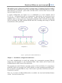
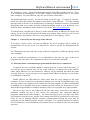
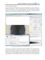
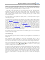
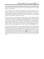
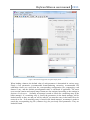
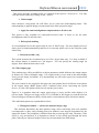
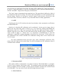
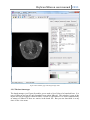
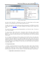
SKYSCAN NV NRecon User Manual Skyscan NV 4/20/2011 SkyScan NRecon user manual 2011 User manual for SkyScan reconstruction program NRecon Index Introduction: NRecon in a nutshell Chapter 1. Installation, configuration and license Chapter 2. General layout and usage of the software 2.1 Start the cluster reconstruction program 2.2 Layout and walk around 2.2.1 The Start page 2.2.2 The Settings and Advanced page 2.2.3 The Output page 2.2.4 The Summary page 2.2.5 The batch manager 2.2.6 Optional functions 2.3 Customize the application Chapter 3. Data format and conventions Chapter 4. How to import a non-SkyScan dataset Introduction: NRecon in a nutshell SkyScan NRecon package is used to reconstruct cross-section images from tomography projection images, mainly the cone-beam X-ray projections. The algorithm implemented is the Feldkamp algorithm. The native SkyScan data are recognized automatically. This program can also reconstruct non-native tomography data, if the file format and file names follow the conventions described in chapter 3, and a corresponding log file is created following the instruction described in chapter 4. The program is provided together with a help file with detailed information on how to use the software. This additional document serves as a manual for quick startup, and it overlaps largely with the online help. There are also a number of related technical notes available upon request. The reconstruction software package consists of 2 programs: the user interface program NRecon and the reconstruction engine NReconServer. The two programs can run either on the same computer or on a cluster of computers. The communication between NRecon and SkyScan NRecon user manual 2011 NReconServer uses a client-server model (a common port). If windows firewall is enabled, you will be asked to unblock it for the server program. Data are shared among the PCs using shared directory via network: please make sure that all PCs involved have access to both input and output directories. A typical configuration (see Figure 1) is a combination of 1 host computer and N (N=1,2,3,4,....) reconstruction nodes, as configuration 1 shown below. Or, you can run it as in configuration 2, with or without extra node PCs. Ideally, the node PCs should be highdefinition: dual (or more) processors, large RAM (minimum 1GB if 8Kx8K reconstruction will be performed), fast FSB, minimum 40GB hard disk (excluding data storage) if 8Kx8K reconstruction will be performed. Figure 1 Typical layouts of NRecon/NReconServer Chapter 1 Installation, configuration and license It is rather straightforward to install and configure the reconstruction program NRecon: simply copy the programs to your destination folder. More details can be found in the installation guide which is part of the online help. The programs run under Windows operating systems (32-bit and 64-bit). It is important to install the 64-bit server program on a 64-bit computer to ensure maximum performance. For the user interface program NRecon, only 32-bit version is provided, which runs on both 32bit and 64-bit systems. There are 2 versions of NRecon/NReconServer available: the local and distributed/cluster version. The local version is free. SkyScan NRecon user manual 2011 The local/free version: please download and install the local NRecon/NReconServer. There is no limitation in functionality. As the name suggests, both programs have to run on the same computer. For each NRecon, only one server can be connected to. The distributed/cluster version: you need a license to run this copy. To apply for a license, please note down the product ID (found in menu Help->About NRecon ...; or in the warning message when no license or an invalid license is found by a distributed version), and send the ID together with a user name and your institution/company name to your distributor or to SkyScan. More information can be found on our website: http://www.skyscan.be. To install license: the NRecon.lic has to be in the same directory as NRecon.exe. By the first startup, you need to fill in the product ID, name and company name exactly as you received from SkyScan (case-sensitive; please use copy-and-paste to avoid typing errors). Chapter 2 General layout and usage of the software If you have a local version, just start up NRecon: the server program will be started up automatically if it was not yet on. You may skip 2.1 which is specific for distributed/cluster version. The NReconServer(local) will only accept connection requested by NRecon running on the same computer. In case of multi-user environment, it is recommended to run only one copy of the server program at the same time: the computation resources are used more optimally. 2.1 Start the cluster reconstruction program and the client-server connections In general, the server program should be started first, but it is not strictly necessary. If you exit the server program, turn off one of the node PCs or unplug one of the network cables while NRecon is on and connected, NRecon will be informed and show the status correctly. However, if you start up a server program while NRecon is already on, you need to re-establish the connection. Neither NRecon nor NReconServer allows more than one copy running on the same computer. In case of multi-user workstation (multiple users can log on simultaneously), only one copy of the server program can be started at a fixed port number: it is then recommended to install the server program only on one (common) account, so that you do not have to worry about different port number or multiple instances of the server program on a single machine. The server only "serves" one NRecon at one time (the active client), but it does hold a numbered waiting list and it will inform all connections (the connected NRecon programs) whenever this status changes. An active client gives up its "privilege" only when it disconnects from the server, and the first waiting client will be promoted to be the active client. In case of multiple NRecon instances, communication among the users may be required to use the limited computer resource efficiently. For a smooth operation in a multiuser environment, it is recommended to disconnect the servers whenever they are not needed any more. SkyScan NRecon user manual 2011 2.2 Layout and walk around Figure 2 shows the typical appearance of NRecon and NReconServer. Little explanation is needed for NReconServer: only the communication port number and the number of threads can be altered by the users. The port number should be the same as that used in NRecon (default to 1) and usually does not require modification. The number of threads influences reconstruction speed. The layout of NRecon is more complicated. Figure 2 Typical appearance of NRecon + NReconServer: the local version There are a few windows on the application window of NRecon: The main display where the images are shown, the reconstruction window which hosts a few pages/tabs (start, settings, advanced, output, summary) for reconstruction purposes, the connection window which shows the status and progress of all servers, the color window which allows you to view the images in the main display in different color and scale. Except the main display, all other windows are so-called dockable windows: you can drag them out of the main window, SkyScan NRecon user manual 2011 or dock them differently than they are shown here. You may customize the appearance of NRecon to your taste and convenience like most windows programs: the last used layout will be saved and loaded automatically at next startup. You can also show/hide these dockable windows by closing the individual windows or via the View menu. Since there is only one display area, a few display modes are used: navigation mode, alignment mode, preview mode, image mode and idle mode. These display modes are coupled to the different pages/tabs on the reconstruction window. In other words, switching from one display mode to another is done by switching from one page to another on the reconstruction window. The color window is also coupled to the display modes, i.e., each display mode has got its own settings for display. A general scenario of reconstruction is the following: after loading a dataset, NRecon will be set at the Start page and the display will be in the navigation mode, where the projections can be viewed; go to the Settings page to check the parameters, usually the display will be in navigation mode to allow you to check the alignment; go back to the Start page to do a preview; NRecon goes automatically to the Output page after reconstructing a slice for previewing, the display will be set at previewing mode, and you can modify the parameters concerning final output image; You may go the Advanced page for further parameters adjustment, or to the Summary page to view the scan parameters and reconstruction parameters; once all parameters are set, go back to Start page to start the full reconstruction or send the reconstruction task to the batch manager. The sections below will give more details on the different pages on the reconstruction window and the batch manager. 2.2.1 The Start page This is the default page when a dataset is loaded, if no post-alignment is set automatically at loading time. This window/page offers possibility to select axial reconstruction range, to start a reconstruction or to submit a batch job. It is coupled to the main display: setting this page active will set the main display to navigation mode in which a shadow image will be shown. Figure 2 is a snapshot taken when this page is set active. To view other shadow images, you can click on the up/down arrows window by clicking on the second button. on the toolbar; or invoke a popup The green line on the main display in the navigation mode indicates the slice for previewing. The dark-red lines indicate the slice range for volume reconstruction. These lines can be dragged to a desired location (left mouse button). The corresponding slice numbers are also shown on the start page, and can be altered from there as well, by either editing or scrolling. Please note, this range indication is only a rough guide due to the cone-beam geometry. Therefore, one should foresee a safe margin or do a preview to confirm when selecting the slices. SkyScan NRecon user manual 2011 The functions provided on the Start page are described here. Preview: This function is provided to adjust the various parameters. It basically reconstructs one slice of choice. To change the slice on which a preview reconstruction will be performed, you can drag on the green line with mouse move, use the spin button, or simply type in a slice number. In preview mode, only the parameters shown on settings/advanced page will be taken into account, while the parameters shown on Output option page will be ignored silently. For example, the region-of-interest option is ignored so that you can draw ROI on the full preview image. When preview reconstruction finishes, the Output option page will be automatically set active, offering you the chance to modify a few output parameters for the final results, such as the dynamic image range, output format, scales, color and etc. The major aim of previewing is to help you adjust parameters. You can always switch back and forth between the pages to adjust them. To help you associate the parameters with result, the slice number (e.g., Prv 0514) is shown on the status bar whenever the preview image is in display. If any change occurs which might result in different image quality, a * will be shown (e.g., *Prv 0514). Fine tuning: A few reconstruction parameters have to be adjusted manually in a try-and-error fashion using the preview function. It requires quite some effort to save the preview images, view them and then make a decision. The "fine-tuning" function is designed to make this adjustment somewhat easier by launching a series of previews. You may adjust one parameter at a time, while keeping all other parameters fixed. In this way, you may tune 4 parameters: post-alignment, beam-hardening correction, ring artifacts correction level and smoothing level. Figure 3 shows the popup window appearing upon clicking on the fine-tune button. You may choose the parameter to tune, and the parameter values are given such that they are centered on the current value (the valid range of the parameters are taken into account as well) with given step size. Once you have set this, you can click on Start to start a series of preview reconstructions. SkyScan NRecon user manual 2011 Figure 3 Fine-tune window Once the preview reconstructions are done, you may use the buttons on the toolbar to scroll. The parameter is adjusted automatically when you scroll. In other words, simply concentrating on the images until you find a satisfied one, and the fine-tuning function is done. In case of doubt on the consistency, there is text information at the top-right of the image, indicating which preview you are viewing; or go to the Settings page, switch the alignment image off, and you will be able to view the preview image and observe how the parameter updates while scrolling. If, accidentally or not, you have changed any parameter which does not correspond to any of the preview images, a * will be shown (e.g., *Prv 0514) on the toolbar, just as in the normal preview case. Start Obviously, this is the button to start a reconstruction. It checks for disk sufficiency and whether you want to overwrite files if there are already there. When the first resulting image is available on the disk, it will be loaded automatically and the Overview page will be set active, showing the first reconstructed slice in image mode. Same as in navigation mode, you may walk through the resulting images by using the buttons. Please note that the images may appear non-sequentially due to work division among multi-threads and multi-computers. Add to batch Instead of reconstructing the volume immediately, you can send the reconstruction task to the batch manager. You can start the batch jobs later. Section 2.3.5 has more details about the batch processing. 2.2.2 The Settings and Advanced page SkyScan NRecon user manual 2011 There are two windows/pages for reconstruction parameters. These two windows offer possibility to change reconstruction parameters for the current dataset. The most frequently used parameters are put in page Settings, and other more advanced parameters are grouped together in page Advanced. The Settings page can be coupled to the main display in 3 ways: alignment mode, preview mode or navigation mode. The alignment mode will be switched on if both the postalignment option and the show option are checked; otherwise the preview mode (if previewing image is available) or the navigation mode will be switched on. You may switch between two modes by check/uncheck the show option: convenient when you are adjusting parameters by looking at the existing preview image. The Settings page is set automatically active after loading if the post-alignment option is checked. Figure 4 shows the settings page with alignment display mode. This display mode is switched on when both the post-alignment option and the show option are checked. The image shown in display is the overlaid image (alpha-blending) of 2 shadow images at opposite positions (180 degrees apart). One of the 2 images is flipped. The intention of this option is to help you choose the correct alignment value at the first stage. However, the 2 images may differ a lot due to the cone-beam geometry and different magnification factors. Therefore, it is always recommended to use the previewing choose the post-alignment value. The initial/default post-alignment value is estimated at loading time. Instead of comparing the original cone-beam projections, we compare pseudo-parallel projections obtained from the cone-beam projections at 0 and 180 degrees. Only the central portion of the projections are used (you may change the portion of data used for post-alignment in Preferences.). If you interrupt/cancel the rebinning, the original version as described above will be used instead. The profiling function is partially enabled: clicking on will show you 2 curves (profiles along the central horizontal line, average over the full vertical length). Together with the profiles, the overlaid image provides a rather interactive way of adjusting the post-alignment value. SkyScan NRecon user manual 2011 Figure 4 The Settings page with alignment display mode. The profile window is also visible Figure 5 shows the Advanced page coupled with navigation display mode. SkyScan NRecon user manual 2011 Figure 5 The Advanced page with navigation display mode When loading a dataset, the default value of each parameter is determined in various ways. Firstly, a few parameters (recommended beam-hardening correction, recommended HU calibration factor) are read from the corresponding configuration file companying each dataset if any, and the default post-alignment value is calculated if applicable. The static cross-section rotation and output image format are also assigned according to the settings in Options->Preferences. Secondly, an attempt is made to search for a matching entry in the batch manager. If a matching entry is found, the parameters in the batch manager will be loaded exactly as they are and you will be asked if you want the entry in the batch file to be removed or not. If no matching entry is found in the batch manager, an attempt is made to search the corresponding log file (<dataset>.log) for previously used parameters. They are loaded if found. SkyScan NRecon user manual 2011 If no parameter found so far, and the check box "load last-used parameters instead of default protocol" in the preferences window is checked, the last-used parameters will be loaded (except the post-alignment value ---which always takes the calculated value for this dataset, the output format, the scale option and the cross-section rotation), if any at all; otherwise the default protocol will be loaded. Alternatively, there are a few ways to alter reconstruction parameters altogether rather than modifying them one by one. You can load a set of reconstruction parameters from a valid log file (generated by NRecon), a valid ini file (generated by ConeRec), a valid protocol template file *.rcp (created by NRecon, see Summary page), or load the last-used parameters specifically. These functions are available through menu Actions. A detailed description of each parameter is given here. Smoothing This is applied to the projection. It smooths each pixel with a MxN neighbourhood, where M is the horizontal dimension and N is the vertical dimension. It reduces noise but may introduce blurring for fine structures. The smoothing level d (number shown on the slide bar) has a range of 1...10. You may use the fine-tuning function to search for a suitable smoothing level. Three smoothing kernels are provided: Box(asym.), Box(sym.) and Gaussian. This can be modified in the Advanced page. In the preferences, the default smoothing method can be specified. The asymmetrical box function has been the default and the only method in the early versions: the smoothing kernel is a box of size MxN, while M = 2*(d/2)+1, and N = 2*d +1. The symmetrical box function: M = N = 2 * ( (d+1)/2 ) + 1, and when d is even, the edge pixels in the box have a weight of 0.5, while the inner pixels have a weight of 1. The 2D Gaussian functions are defined as: sigma = 0.25 + d*0.25 for d>0. In general, the Gaussian kernel is preferred. Misalignment compensation (post-alignment) This compensates possible misalignment during acquisition. It is an important parameter: wrong alignment compensation would cause tails, doubling or blurring in the reconstructed image; and it may differ slightly from one dataset to another on some scanners. Though the estimation accuracy is improved a lot, it is still a parameter to be adjusted in try-and-error fashion: the fine-tuning function makes this task somewhat easier. More details can be found in the FAQ list of the online help file coming with NRecon program. Object larger than field of view This option indicates that the object is larger than field of view. This function only influences the way how the reference (air) intensity is defined. As well known, the shadow image is converted before reconstruction: value = ln(I0/I), where I is the intensity in the shadow image and I0 is the reference (air) intensity. If this option is not checked (default), I0 is searched line per line (maximum of the line); otherwise a theoretical maximum (for 16 bit data, I0=65535) is used. Please do not check this option unnecessarily: the resulting image might SkyScan NRecon user manual 2011 be less sharp otherwise. Check this option only when your object extends beyond the FOV boundary at both sides in any of the shadow images! Ring artifacts reduction and defect pixel masking This option reduces ring artifacts. It is applied on the projections before any other preprocessing steps. The mean projection image in <DatasetPrefix>_arc.tif is used for this purpose: if absent, NRecon will create it automatically. You can select the depth of correction in the slider with 20 positions (1, 2, ..., 20). The value is determined in try-anderror fashion: you may use the fine-tuning function to adjust this parameter. It is generally not recommended to use a unnecessarily high value: blurring may occur. This method is sufficient for most scans with small variations in camera responses, but has nearly no effect if one camera pixel has varied sensitivity during the same scan (e.g., due to beam-hardening), or is completely dead (0 sensitivity). We call these pixels defect pixels. For SkyScan X-ray CT scanners, one may specify a threshold to detect the defect pixels in the Advanced page by checking button Defect pixel masking. For more details on how a defect pixel is found automatically and how it is corrected, please refer to the FAQ list on the online help. Beam-hardening correction This option compensates beam-hardening effect by linear transformation in the software. Depth of correction (0, 1, ..., 100) can be selected according to object density. Same as postalignment, this parameter needs manual adjustment (and experimenting) by visualizing the resulting images (the profiling function will help you during visualization). You may use the fine-tuning function to adjust this parameter. A higher order (up to 5-th order) polynomial function may be used to do beam hardening correction, but this is considered as a non-standard option. This option can be switched on in the advanced page by checking button 5-th order beam hardening corr. For more details refer to the FAQ list on the online help. CS rotation (in deg.) This option rotates the resulting cross-section image by a fixed angle. It does not influence the image quality in any way. The value shown is only valid for current dataset: the value may be taken from your preferences, or from the default reconstruction protocol. Tip: if you want the image to be re-oriented in a certain way, first do a preview, then on the preview image you may draw a line which you wish to be rotated to the horizontal position. On the profile window, the orientation of the line (angle between the line and horizontal direction: 0 - 180 degrees) will be given. The cross-section rotation angle should then be: the current value + line orientation. 5-th order beam hardening correction SkyScan NRecon user manual 2011 This option becomes available when it is enabled in the Options->Preferences. You may view the current values by clicking on the ? button. Undersample Once checked, a drop-down list will allow you to select the undersampling factor. The undersampling is applied during reconstruction in the back-projection stage. Apply the same misalignment compensation to all sub-scans This option is only available for connected/oversized scans. It forces to use the same misalignment value for all sub-scans. Defect pixel masking It is recommended to use this option only in case of "hard" rings. For more details on how a defect pixel is found automatically and how it is corrected, please refer to the FAQ list on the online help. Reconstruct 180+ only This option instructs the reconstruction to use 180+ degree data only. It is only available if the current dataset is scanned over 360 degrees. You can specify the starting angle (in degree) from which the data can be used. 2.2.3 The Output page This window/page offers possibilities to adjust parameters which influence the output images in format, size, color or dynamic range. It is coupled to the preview mode in the main display if any preview image is available. It is automatically set active after a preview reconstruction is performed. The color control is also coupled to this page: the color palette shown will be the color palette in the output image (BMP format only). Confusion often arises concerning the option Inverse: it is the color palette which inverts, not the pixel values. Figure 6 is a snapshot when the output option page is active and the main display is in preview mode. The preview image at slice 532 is available in full image size, and the user has selected a Region Of Interest (ROI), which can be resized and moved by left-mouse button. The individual options are explained here below. Histogram window --- choose the dynamic image range This function determines the data dynamic range when converting from real numbers (reconstruction is done using floating-point real numbers) into integers determined by the output file format. The histogram is obtained from the previewing slice only. Therefore, if the object is very non-uniform, it is important to choose a slice which goes through the dense parts of the object; otherwise higher values may be truncated in the final image. SkyScan NRecon user manual 2011 Figure 6 The Output page with preview display mode . The histogram can be displayed either in linear or logarithm scale: double-clicking with left mouse button on the histogram will switch between the 2 modes. The image range can be altered in 3 ways: dragging one of the 2 dark purple lines on the histogram with mouse move (holding left mouse-button); press button Auto to get default range; or change the values manually by clicking on the range itself. By manual modification in the range (the 3rd way), you are allowed to give a range beyond the boundaries of the histogram. If the higher limit is SkyScan NRecon user manual 2011 set to be lower or equal to the lower limit, the range will be indicated as "range not defined". In case of "range not defined", a preview reconstruction will be performed automatically to find the "automatic" range before doing any reconstruction. The "auto" range is determined in an empirical way. The upper limit is defined as 140% of the maximum in the preview image. The lower limit is defined as 3% of the maximum in the preview image. However, if you preset "positive image" in the Options->Preferences, the lower limit will be fixed at 0, which is a very reasonable choice in many applications. In HU Checking the box In HU switches the units from absolute value (attenuation coefficients) into Hounsfield unit. If this box is checked, HU calibration can be performed. On the preview image, draw a ROI in the area where HU value is known (e.g., 0 for water) by clicking and holding the right-mouse while the CTRL key is pressed, and drag. By right-mouse-button release a window will pop up (see Figure 7): fill in the known value for this region to calibrate HU. Click on OK to apply it. Please note: it is important to hold-and-drag to start HU calibration; a right-click (without dragging) will activate the view menu. If you want to use this calibration on the control software, the calibration scaling factor can be found on the overview page. For more information about pixel unit (grey value, attenuation coefficient, HU), please refer the FAQ list in the online help. For more information on HU calibration, there is a technical note available. Figure 7 The pop-up window for HU calibration Reconstruct ROI This option enables reconstruction of a region of interest. The default ROI is a rectangle. To force it to be a square, check Square ROI. For technical reasons, the width and height are always a multiple of 4 (For example, you have chosen 403x403 as a ROI, but it will be forced to be 400x400). You can resize or move the ROI using left mouse button. Scales/Labels on SkyScan NRecon user manual 2011 Check this box to have the scales and labels hard coded into your final images. It does not take extra time to draw them, but you might lose information at the edges in case of reconstruction of a small ROI. Destination Specify the output dataset. The filenames of cross-section images are fixed: <dataset>_rec.bmp, <dataset>_rec.tif or <dataset>_rec.jpg. You can change the output directory. The default output directory is determined by your settings in Preferences: either the input folder itself or a sub-folder in it. Click on button Browse to make modifications. File format Four output formats are provided: 8-bit BMP (0-255), 16-bit TIFF (0-65535), 8-bit JPG (0255) and 8-bit PNG (0-255). To convert the floating-point cross-section image to the limited precision of these formats, the dynamic range showing in the histogram section is used: values within the dynamic range are mapped into [0,255] in BMP/JPG/PNG format or [0, 65535] in TIFF format, and values out of range are assigned 0 (if below lower limit) or the maximum value (if above maximum limit). For the JPG format, you may specify a compression factor between 50% and 100% in Options->Preferences: it is recommended to use 100% to keep the most details. PNG format is added later: it allows lossless compression and yet provides a good compression factor. A non-standard format F4F is provided. More information can be found in the FAQ list: What is the non-standard float format F4F and how/why to use it? To retrieve pixel values, please refer to the FAQ list in the online help: How to convert pixel value from gray-level to its physical unit: linear attenuation coefficient in 1/mm? 2.2.4 The Summary page This window/page offers the possibility to view all parameters currently in use at one glance. It is coupled to the image mode in the main display. Note that the color scale shown (you may change it at will) has no correspondence to the used color palette in the final image This page is automatically set active during reconstruction after the first cross-section image is reconstructed and found. Sometimes this means that you will only see the image towards the end of the reconstruction. To use as little computer resource as possible, only the first image is shown. You can save the current settings into a template/protocol file (*.rcp) by clicking on the button Save settings as .... Note that you can alter the values for some of the parameters by double-clicking on them. See Figure 8 for a snapshot image when the overview page is active and the main display is in image mode. SkyScan NRecon user manual 2011 Figure 8 The Summary page with image display mode 2.2.5 The batch manager The batch manager (see Figure 9) enables you to make a list of jobs to be launched later. It is part of NRecon and can be only launched from within NRecon. This window is part of the layout and can be toggled visible/invisible, resized or repositioned. It is shown automatically at startup of NRecon if there are entries in the batch file. But you can show/hide it at any time via the view menu. SkyScan NRecon user manual 2011 Figure 9 The batch manager An entry in the batch file is identified by two items: the input dataset and the output directory. It is not possible to have two identical entries in the list. To add a job into the list: load the dataset and adjust the parameters accordingly, press add to batch button on the Start page. You will be reminded if an identical entry is found in the batch. The entries in the batch are not removed automatically, even if the job is done. You have to remove them manually. To start the batch, click on Start batch. Only those entries with status pending will be processed. If one of the entries fails, you can submit it again (error information is saved in NRecon_error.log in the system directory): select it with left-mouse click, and click on button Submit again. To view details of a batch entry, click on it and its contents will be shown at the right panel. You can modify the parameters by double-clicking on the items (some items are not modifiable, such as the dataset or output directory which define the entry), but no consistency check is applied here. To modify parameters safely, it is recommended to load the dataset and submit it again: double-clicking on a batch entry will load the dataset and its parameters to the main window. 2.2.6 Optional functions A number of optional functions have been added to the software. Most of these functions can be found in the menu Actions as shown in Figure 10. Some of the functions are only available for a certain type of scan, or when certain information is available. Only a very brief description is given here. For more details, see either the online help or technical notes. Adjust and reconstruction an oversize scan SkyScan NRecon user manual 2011 It is reported that some oversize scans are not connected well. This option offers you the possibility to adjust the connection and/or to smooth the connections. Figure 10 Optional functions available in menu Actions X/Y alignment with a reference scan This option is available only when a corresponding pre- or post-scan can be found. The option “Show/Modify thermal shifts” is an helping tool when the x/y alignment option is used. 2.3 Customize the application NRecon can be customized in a few aspects: the layout, the default behavior and the set of reconstruction parameters. To customize the layout, drag and drop are the obvious ways to get the layout to your desire. Once this is done, the layout is saved automatically. If you have a set of scans with similar acquisition conditions and you wish to them in similar way, there are 2 ways to achieve this. The easiest way is to use accompanying each set of cross-section images: take one typical scan, reconstruction parameters accordingly and then reconstruct it, a log file will reconstruct the log file adjust the be created SkyScan NRecon user manual 2011 automatically together with the reconstructed images (*_rec.log); load this log file for all other scans to be reconstructed via menu Actions->Load parameters from a log file. A second way is to use the so-called reconstruction protocol files: take one typical scan, adjust the reconstruction parameters, go to the Summary page on the reconstruction window, and save the parameters as a *.rcp file. This RCP file can be either loaded individually via menu Actions->Load parameters from a protocol file, or can be set as the default protocol file via the Preferences. You can customize the default behavior via the menu item Options->Preferences. More details can be found in the online help. Chapter 3 Data format and conventions As well known, a reconstruction program takes the projection images (also called shadow images) as input, and gives the cross-section images as output. The projection images are taken during acquisition over 360 degrees or180+ degrees. For a reconstruction to succeed, this projection dataset has to be intact and is accompanied with necessary information about acquisition. Only one input data format is recognized by NRecon: 16-bit TIFF format. All projection image file names use the same convention. For each dataset, you can give it a name, or a prefix. For example, we have a 207-projection dataset named "sample". The convention for a projection file is: dataset name followed by a 4-digit (or 8-digit) index, starting from 0, namely, sample0000.tif, sample0001.tif, ...., sample0206.tif. The acquisition parameters are saved in a text file ( sample_par.txt, or sample_cfg.txt, or sample.log). The log format is the standard format, while the other formats are from earlier versions of acquisition software and are only recognized for backwards compatibility. It is worth noting that NRecon first searches for sample_par.txt, then sample_cfg.txt, and at last sample.log, as a log file might be created later on, either manually or by other software. A dataset cannot be loaded or reconstructed successfully if any of the following occurs: 1. Any projection file is missing; 2. The acquisition parameter file is missing or corrupted; 3. Inconsistent information between the text file and the projection image. SkyScan control programs also produce an additional TIFF file (sample_arc.tif) for ring artifact reduction. If this file is absent, NRecon will make one at the time of reconstruction. Therefore, the *_arc.tif is considered as part of input, but is not strictly necessary. Contrary to what many users believe, the sample_spr.bmp and sample_sp2.bmp are not considered part of input and are not used by NRecon, but they are used for display purpose by DataViewer and CTan. A special case is the so-called connected or oversize scan. Suppose we have a scan with 3 bed positions (i.e., 3 sub-scans), we would expect the following set of TIFF files: (sub-scan 1) sample~000000.tif, sample~000001.tif, ...., sample~000206.tif; (sub-scan 2)sample~010000.tif, sample~010001.tif, ...., sample~010206.tif; (sub-scan 3)sample~020000.tif, sample~020001.tif, ...., sample~020206.tif. For each sub-scan, there is a text file ( sample~00_par.txt, sample~00_cfg.txt, or sample~00.log). In case the text file is a log file, a global log file may also exist: sample.log. SkyScan NRecon user manual 2011 The output cross-section datasets use the same convention as the input, but the index now is the cross-section number. To distinguish the input and output, "_rec" is appended to the dataset name. Take the example above, the resulting cross-sections would be: ......, sample_rec0100.bmp, sample_rec0101.bmp, ...... . For an oversized scan, the sequence number is automatically shifted to form one complete volume. Chapter 4 How to import a non-SkyScan dataset It is possible to import a non-SkyScan dataset to NRecon, if a few simple rules can be followed. As described in chapter 3, the file name convention should be followed. Each projection file should be a 16-bit TIFF image. If there are more than 10000 projections, the number of digits for the sequence should be 8, instead of 4. The pixel size information (for those who use Visual C++, biXPelsPerMeter and biYPelsPerMeter; for those who use MATLAB, tag resolution) should be filled correctly. A corresponding log file should be available. If you have created a series of TIF files: MyScan_0000.tif, ..., MyScan_9999.tif, the corresponding log file should be named MyScan_.log. An example is given here. The comments are given by lines starting with ";". These comment lines can be retained in the log file: they are ignored by NRecon. # Begin of log file ######################################################################## [System] Scanner=SkyScan1172 ; A string with at least 11 characters. Typically, the first 7 characters refer to the company, and the last 4 characters are 4-digits --; scanner model (in case of non-digits, it is interpreted as 0) . Model number 0-2999: X-ray systems; ; Model 3000-3999: Optical scanner systems ; Please respect the number of letters: hardcoded inside NRecon. Instrument S/N=2 ; info only: serial number of the scanner [Acquisition] Optical Axis (line)= 256 ; Important parameter: the central slice in which the x-ray hits the detector perpendicularly; Object to Source (mm)=100 ; Important parameter: distance between image center and the x-ray source. If the distance is > 10m, it is assumed that it is a ; parallel beam scan. Number Of Files= 401 ; Info only. Number of projections, dimension and pixel . information are actually obtained/confirmed from the TIFF files Number Of Rows= 512 ; info only Number Of Columns= 512 ; info only Image Pixel Size (um)=15.98 ; info only. The pixel size is actually read from the header of the 16-bit TIFF files. ; Important! For cone-beam geometry: the concept of "virtual detector" is exploit. More specifically, the detector is ; assumed to be centered at the FOV. ; Therefore, the pixel size in the TIFF header should have been scaled accordingly. ; Alternatively, one may use the non-standard key Scaled Image Pixel Size (um) to indicate pixel size scaled at image center. Linear pixel value=0 ; Non-standard key. Default: 0, exponential attenuation case; 1: Scaled Image Pixel Size (um)=15.98 Linear case ; -1: inverse linear SkyScan NRecon user manual 2011 ; Non-standard key. When present, it has higher priority than pixel information in TIF header Exposure (ms)=100 ; info only Rotation Step (deg)=0.900 ; Important parameter Table Feed (micron)=0.0 ; Spiral CT specific: table movement length per rotation step ; Positive: table movement direction coincides with projection vertical direction Use 360 Rotation=YES ; Important parameter: YES or NO (360 or 180+) Flat Field Correction=ON ; info only Rotation Direction=CC ; Important parameter: TRY IT OUT TO SEE IF IT SHOULD BE cc OR cw. Almost all SkyScan scanners have rotation direction CC. Type of Detector Motion=STEP AND SHOOT ; info only Scanning Trajectory=ROUND ; info only. Spiral scan is recognized by entry “table feed” Study Date and Time=Aug 10, 2005 15:13:11 ; info only # End of log file ########################################################################