1
29
Cobolt 06-01 Series
5.5.
Pin assignment
5.5.1 MLD
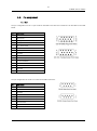
The pin configuration for the 15-pin D-SUB on the MLD Laser Head and control box are described in the table
below.
Pin
MLD model
1
LED1 (Laser on)
2
LED2 (Error)
3
Analog modulation
4
0V (ref pin 1,2,3,5,6,7,8,11,12)
5
Key + Boot loader
6
Interlock
7
RS232TX
8
RS232RX
9
Spare
10
0V GND (ref pin 15)
11
On/off modulation
12
VBUS
13
Not used
14
Not used
15
+5V input
The pin configuration for the RS-232 socket on the MLD control box.
Pin
MLD model
1
Not connected
2
RS232TX
3
RS232RX
4
Not connected
5
GND
6
Not connected
7
Not connected
8
Not connected
9
VBUS