1
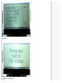
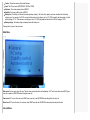
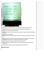
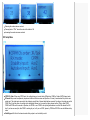
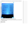
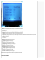
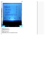
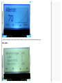
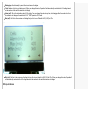
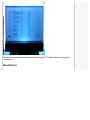
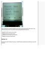
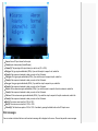
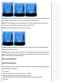
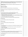
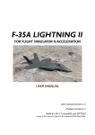
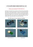
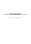
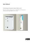
My favorites ▼ | Sign in
nextcopterplus
Search projects
Open source fully featured flight controller code
Project Home
Search
Downloads
Current pages
Wiki
Issues
Source
for
Search
OpenAero2_User_Guide
OpenAero2 - User guide (V1.0)
Updated Feb 16, 2013 by [email protected] om
The OpenAero2 User Guide (V1.0)
What is OpenAero2?
OpenAero2 is an aeroplane stabilising software for the KK2 multicopter board. You put the programmed KK board in between your receiver and
the servos in your aircraft. When deactivated, OpenAero2 just passes the servo signals from your receiver to the servos. When activated, the
gyros on your KK board are used to move the servos to counteract any unwanted movement of the aircraft.
OpenAero2 has eight output channels which can all mix from five PWM RC channels in PWM mode, and eight RC channels in CPPM mode. In
addition, four preset channel sources and two on-board RC mixers can be used as inputs. Each of the eight output channels can have any or all
sensors mixed together.
What models can OpenAero2 be used with?
OpenAero2 have a completely flexible mixer which allows it to control just about anything, but comes with three preset mix tables.
Aeroplane
In aeroplane mode there are four stabilised outputs - Left Aileron, Right aileron, Elevator and Rudder. For those needing a throttle control, you can
just take the throttle output of your receiver directly to the ESC for your motor.
In CPPM mode there are five stabilised outputs - Left Aileron, Right aileron, Elevator and Rudder, plus a copy of the throttle signal from the
receiver on M1.
Read more about the differences between PWM and CPPM receivers elsewhere in this Wiki.
Flying Wing
Flying wings normally have delta/flaperon mixing done by the transmitter. This allows you to set the aileron/elevator mixing as best suits you and
your aircraft. When these signals pass through the OpenAero2 software the gyro stabilising has to accommodate the flying wing channel mixing.
For instance, in response to pitch input, the standard version of Openaero2 would simply adjust the elevator servo. However the flying wing version
adjusts both flaperons to have the desired effect.
In flying wing mode there are three stabilised outputs - Left Flaperon, Right Flaperon and Rudder.
For those needing a throttle control, you can just take the throttle output of your receiver directly to the ESC for your motor.
In CPPM mode there are four stabilised outputs - Left Flaperon, Right Flaperon and Rudder, and a copy of the throttle signal from the receiver on
M1.
Camera Stability
In Camera stability mode both gyros and accelerometers are enabled to stabilise 3-axis camera mounts. See the separate guides for setting up
camera stability.
How do I connect up my model?
A note about servo connections There is no +5V power supplied to M2 to M8, so you must supply your own 5V to any of M2 to M8 via a
BESC or battery pack.
Receiver connections
For a standard multi-wire PWM receiver you need to use the normal PWM inputs of the KK board. However, the THR input of the KK board has
been repurposed to be the secondary aileron input.
If you have a CPPM receiver, connect the single wire to the RUDDER input. Also, don't forget to enable CPPM mode in the RC Setup menu.
AIL: Aileron signal input (required)
ELE: Elevator signal input (required)
THR: Second aileron signal input (optional)
RUD: Rudder signal input (optional) CPPM input
AUX: Stability switch input (required)
Please make careful note that for OpenAero2 to output servo signals, at least two inputs, including the stability switch input MUST be connected
to the KK2 board.
Using the OpenAero2 menus, you can set up how you wish to control stability and autolevel. This will be discussed later in the guide.
Here is a diagram showing how to connect up a PWM receiver.
CPPM channel order
CPPM mode requires that the receiver and a transmitter can reallocate channels if not matching the JR/Spektrum or Futaba channel order.
OpenAero2 supports JR/Spektrum and Futaba CPPM channel order as shown below.
JR/Spektrum
CH1:
CH2:
CH3:
CH4:
CH5:
CH6:
CH7:
CH8:
Throttle
Aileron #1
Elevator
Rudder
Gear switch
Aileron #2
Aux 1
Aux 2
Futaba
CH1: Aileron #1
CH2:
CH3:
CH4:
CH5:
CH6:
CH7:
CH8:
Elevator
Throttle
Rudder
Gear switch
Aileron #2
Aux 1
Aux 2
Servo connections
For conventional aeroplanes the connections are as follows:
M1:
M2:
M3:
M4:
M5:
M6:
M7:
M8:
Throttle (CPPM only)
Free channel or Pitch/Tilt for camera stabilising
Free channel or Yaw/Pan for camera stabilising
Free channel or Roll for camera stabilising
Elevator
Left aileron
Right aileron
Rudder
For flying wing models the connections are as follows:
M1:
M2:
M3:
M4:
M5:
M6:
M7:
M8:
Throttle (CPPM only)
Free channel or Pitch/Tilt for camera stabilising
Free channel or Yaw/Pan for camera stabilising
Free channel or Roll for camera stabilising
Elevator
Left elevon
Right elevon
Rudder
The LCD Menu System
The Status Screen
The status screen gives you a continually updated display of the battery status, flight modes and any error messages. For performance reasons
the status screen will switch back to the idle screen after a short interval. The interval defaults to 5 seconds but can be set to up to 30s in the
General Menu.
Status screen
Idle screen
Mode: The current mixer mode
Version: The version number of the loaded firmware
Input: The RC input mode (CPPM/PWM1, PWM2 or PWM3)
Autolevel: The current autolevel status (ON/OFF)
Stability: The current stability status (ON/OFF)
Battery icon: The battery icon shows the remaining battery capacity. The limits of the capacity meter are calculated from the battery
settings menu. For example, if a 3S LiPo is used and the minimum cell voltage is set to 3.7V (370) the graphic will show empty at a total
battery voltage of 11.1V. If the maximum cell voltage is set to 4.2V (420) the graphic will show full at a total cell voltage of 12.6V.
Battery voltage: The battery voltage is displayed under the battery icon
Pressing button 1 goes to the main menu.
Main Menu
Main menu The main menu stops the loop. The main menu controls should be self-explanatory. LEFT exits to the status menu RIGHT goes
down into a submenu UD/DOWN moves through the menu list
Sub menus LEFT exits to the main menu RIGHT open up an item to edit UD/DOWN moves through the sub menu list
Menu item LEFT resets the item to its minimum value RIGHT saves the item UD/DOWN increments and decrements the item
General Menu
Mode: Allows you to select from the input preset mixers. Currently there are presets for dual-aileron aeroplane and flying wing.
Orientation: Remaps the sensors so that you can mount the board vertically (buttons down) in space-restricted areas.
Contrast: Allows you to change the contrast of the LCD. See below.
Status time: Allows you to set the amount of time the status screen is displayed until it is replaced by the idle mode screen. Settable from
1 to 30 seconds.
RC mix: Enables the two on-board RC mixers.
LMA timeout: Allows you to set the amount of time without RC activity before the Lost Model Alarm goes off. Setting to zero disables the
alarm.
Camera stab.: Setting this to ON allows the board to function without an external RC source. Use only for stand-alone camera stability.
Camstab servo rate: If Camera Stab is ON, you can increase the servo refresh rate on M1 to M4 to 300Hz.
Acc LPF: Allows adjustment of the accelerometer Low-Pass Filter from 1 (infinite) to 64 (about 1 Hz)
CF factor: Controls the fusion of Accelerometer and Gyros. The higher the number the faster as gyro is favoured, the lower the more
accurate but slower.
Yaw magic: Automatically centers the Yaw axis when in heading hold mode if the yaw has drifted off-center.
Adjusting LCD Contrast
Reducing the number reduces contrast.
Pressing button 1 "Def." returns the value to the default of 38.
Increasing the number increases contrast.
RC Setup Menu
CPPM Ch. Order: When using CPPM input, this setting allows you to select either JR/Spektrum (TAER) or Futaba (AETR) channel order.
RX mode: Many users have previously experienced trouble with their receivers and OpenAero. For many it was because they did not use a
rudder input. The rudder input was used by the software to signify that all channel data had been received. Synching on the rudder was called
PWM1. Next I tried the option of synching on the stabilisation channel as it is normally a higher channel number, That is called PWM2.
PWM1 and PWM2 are the same as in OpenAero, but PWM3 is new. PWM3 is for synching with whatever is on that fifth channel the KK2
has. If you have no servo jitter, then PWM1 is working for you, but if you use PWM, please try PWM2 and PWM3 to see what difference they
make.
Stability input: Set this to the channel number that you plan to use for stability control.
Autolevel input: Set this to the channel number that you plan to use for autolevel control. It can be the same as for stability if you like.
2nd aileron: Set this to the channel number that your radio uses for the second aileron channel.
Preset 1 to Preset 4: When using a camera mount which is stabilised but not necessarily controlled, you need a fixed offset to feed that
channel. These can be set up here.
Stability Control Menu
Mode: This setting determines how the stability is to be controlled. There five options.
1.
2.
3.
4.
OFF: Always off
Autochan: On when the channel set as "Autochan" in RC settings is more than 50%
Stabchan: On when the channel set as "Stabchan" in RC settings is more than 50%
3-pos: Stability on when the channel set as "3-pos" in RC settings is more than 33%. Autolevel also on when the channel set as 3-pos in RC
settings is more than 66%
5. ON: Always on
Roll P Gain: PID Proportional gain for the roll gyro
Roll I Gain: PID I-term gain for the roll gyro
Roll D Gain: PID Differential gain for the roll gyro
Pitch P Gain: PID Proportional gain for the pitch gyro
Pitch I Gain: PID I-term gain for the roll gyro
Pitch D Gain: PID Differential gain for the pitch gyro
Yaw P Gain: PID Proportional gain for the yaw gyro
Yaw I Gain: PID I-term gain for the roll gyro
Yaw D Gain: PID Differential gain for the yaw gyro
Note: The function of PID gain controls is outside the scope of this basic User's Guide.
Autolevel Control Menu
Mode: This setting determines how the stability is to be controlled. There five options.
1.
2.
3.
4.
OFF: Always off
Autochan: On when the channel set as "Autochan" in RC settings is more than 50%
Stabchan: On when the channel set as "Stabchan" in RC settings is more than 50%
3-pos: Stability on when the channel set as "3-pos" in RC settings is more than 33%. Autolevel also on when the channel set as 3-pos in RC
settings is more than 66%
5. ON: Always on
Roll P: PID Proportional gain for the roll accelerometer
Pitch P: PID Proportional gain for the pitch accelerometer
Roll trim: For fine roll tuning of the autolevel.
Pitch trim: For fine pitch tuning of the autolevel.
Expo Menu
Aileron: Aileron expo in %.
Elevator: Elevator expo in %.
Rudder: Rudder expo in %.
Differential(%): This feature is not implemented in this release.
The on-screen graph is drawn using the actual expo table and so gives you an accurate view of the response curve.
Battery Menu
Battery type: Used internally to preset the min and max cell volatges.
Cells: Number of cells in your battery pack. When you change this value, OpenAero2 will automatically recalculate the LVA voltage based
on the number of cells and the minimum cell voltage.
Alarm (mV): This is the low battery alarm (LVA) setting. You can change this value at any time, but changing either the number of cells or
the minimum cell voltage will over-write the LVA. "1000" equales to 10.00 volts.
Max (mV): Set this to the maximum cell voltage that you like to use. Defaults to 420 (4.2V) for LiPo.
Min (mV): Set this to the minimum cell voltage that you like to use. defaults to 360 (3.6V) for LiPo. When you change this value, OpenAero2
will automatically recalculate the LVA voltage based on the number of cells and the minimum cell voltage.
RC inputs Screen
The RC inputs screen shows you the current values received by the system in either PWM or CPPM mode. In CPPM mode, only the first five
channels are shown.
Pressing button 4 "Cal." performs a stick centering calibration. This should make all the numbers on the right-hand column drop to zero. Make
sure all controls are centered and throttle at minimum before calibration.
Pressing button 3 'Failsafe" saves the current stick positions to the M1 to M8 failsafe setting. The servos will adopt this position in the event of a
loss of input signal. Note that most receivers will still transmit the last known RC values if it loses the TX signal, so this is no test of failsafe. You
need to physically disconnect the receiver. It is recommended that receivers with built-in failsafe be set up and used.
Sensor Inputs Screen
The sensor inputs screen shows you the current values of all sensors. Pressing button 4 "Cal." calibrates the accelerometers. The gyros are
calibrated at start-up.
Balance Meter Screen
The balance meter screen shows you a graphical representation of where the board considers "down" to be. Pressing button 4 "Cal." calibrates
the accelerometers. A detailed description of the correct use of this screen is given in the section "Initial setup and calibration".
RC Mixer 1 and 2
There are two dedicated mixer channels MIX1 and MIX2. These can be used by any of the output channels M1 to M8 as a source. You can
therefore do delta, taileron, elevon etc mixing with OpeAero2 without needing special transmitter mixing functions.
Source A: Set the first channel source to be mixed here.
Volume (%): Set the amount of channel A required.
Source A: Set the second channel source to be mixed here.
Volume (%): Set the amount of channel B required.
Mixer Menu 1 to 8
Each of the mixer menus M1 to M8 works in the same way - a selected RC channel is manipulated and mixed with the sensors to result in the
desired effect.
Source: Source RC input channel for this output.
Polarity: Input channel polarity (Normal/Reverse).
Volume(%): The percentage of the input channel you wish to use (0% to 125%).
Roll gyro: Roll gyro signal enable/disable (Off/On). If you wish this output to respond to roll, enable this.
Polarity: If the response is backwards to what you need, set this to Reversed.
Pitch gyro: Pitch gyro signal enable/disable (Off/On). If you wish this output to respond to pitch, enable this.
Polarity: If the response is backwards to what you need, set this to Reversed.
Yaw gyro: Yaw gyro signal enable/disable (Off/On). If you wish this output to respond to yaw, enable this.
Polarity: If the response is backwards to what you need, set this to Reversed.
Roll acc: Roll accelerometer signal enable/disable (Off/On). If you wish this output to respond to the roll accelerometer, enable this.
Polarity: If the response is backwards to what you need, set this to Reversed.
Pitch acc: Pitch accelerometer signal enable/disable (Off/On). If you wish this output to respond to the pitch accelerometer, enable this.
Polarity: If the response is backwards to what you need, set this to Reversed.
Min(%): The minimum servo travel limit -125% to 125%.
Max(%): The minimum servo travel limit -125% to 125%.
Failsafe(%): The failsafe servo position -125% to 125%. Over-ridden by pressing the failsafe button on the RC Inputs screen.
Error messages
If an error or alarm is detected the buzzer will sound and a message will be displayed on the screen. There are five possible screen messages.
Sensor Error: When the board is powered up it must remain still so that the gyros can be accurately calibrated. It the boards detects movement
during calibration, this error will be displayed. To clear this error, repower the board while keeping the board still.
Battery Low: If you are using the board to monitor the battery voltage, when the current battery voltage falls below the set alarm point, this
message is shown. If you are not planning to monitor the battery voltage, please set the LVA to zero.
No Signal: This message will be displayed when the board detects a loss of RC signal.
Lost Model: Approximately one minute after the last detected RC input, the Lost Model buzzer will sound and this message will be displayed.
The alarm can be cancelled with any stick input.
Throttle High: PWM does not require a throttle input in OpenAero2. In CPPM mode however, the throttle signal is passed through the board and
appears as a PWM signal on M1. As a safety measure, if the board is powered up with the throttle set to more than about 5%, the oupts will be
disabled, an alarm will sound and this message will be displayed.
How do I set up OpenAero2?
Stability and Autolevel switching
Due to countless requests you now have absolute freedom in how to enable these modes. In the Stability and Autolevel Settings menus you can
select which method of control you wish to use.
OFF: Always off
Autochan: On when the channel set as "Autochan" in RC settings is more than 50%
Stabchan: On when the channel set as "Stabchan" in RC settings is more than 50%
3-pos: Stability on when the 3-pos switch is more than 33%. Autolevel also on when the 3-pos switch is more than 66%
ON: Always on
3-pos switch The three-position switch mode allows you to have both Stability and Autolevel on one switch, but have them selectable. The way it
works is this: For the switch position between minimum and about 33% = Stability off, Autolevel off. For the switch position between 33% and
about 66% = Stability on, Autolevel off. For the switch position above 66% = Stability on, Autolevel on.
RC Setting defaults Stabchan = GEAR (AUX input on KK2 board) Autochan = GEAR (AUX input on KK2 board) Flapchan = THROTTLE
(THROTTLE input on KK2 board)
Initial setup and calibration
The first time you set up OpenAero2 you will have to adjust a few things to suit your radio gear and particular usage.
Step 1: Model type Go into the General menu and change the Mode to that which suits your model. The default is Aeroplane.
Step 2: RC settings
Set the Rx mode to suit your radio. Unless you are using CPPM, start with PWM1. CPPM users select CPPM.
If you are using CPPM, also select the channel order between either JR/Spektrum or Futaba.
Select which input channel you plan to use for stability. PWM users will normally select the fifth channel (GEAR) as that corresponds to the
fifth (AUX) input on the KK2. CPPM users can pick any unused channel.
Select which input channel you plan to use for autolevel. PWM users may select the unused throttle input (THROTTLE) or double-up the two
functions on the fifth channel (GEAR). CPPM users can pick any unused channel.
If your radio carries the second aileron channel on a channel different to the default of FLAP (channel 6) set that here too.
Step 3: Stability settings
For now, just alter the Mode as described above in "Stability and Autolevel switching".
Step 4: Autolevel settings
For now, just alter the Mode as described above in "Stability and Autolevel switching".
Step 5: RC check
Go to the RC Inputs screen and switch on your transmitter and receiver. You should immediately see values appearing in both columns next
to each connected channel.
Make sure all the tranmitter channels are centered and the throttle to minimum, and press button 4, under the screen label "Cal." This
performs a stick centering calibration.
The right-hand column should now all be zero and change +/-1000 or so at the extremes of throw.
Step 6: Servo direction
Once returned to the status menu, the servos should be activated and you should be able to control all outputs with the transmitter. Please
make sure that stability and autolevel are both OFF to continue. Their status can easily be seen in the status menu.
Move all surfaces and check that they move as expected. While you can reverse the channels in the M1 to M8 mixers, it is best to reverse
them in the transmitter first.
Step 7: Gyro direction
Now, switch on stability control while leaving autolevel OFF.
Pitch the nose of the model up and down while watching the elevator. The elevator should move to counteract the pitching. Pitching the nose
UP should make the elevator move DOWN.
If this is not the case, you can reverse the pitch gyro in the M5 mixer menu.
Roll the model left and right while watching the ailerons. They should also move to counteract the rolling. Use the M6 and M7 mixer menus to
reverse the roll gyro as required.
Finally, yaw the model left and right while observing the rudder. Adjust the M8 mixer menu to reverse the yaw gyro as required.
Step 8: Auto-level setup
Firstly, go into the balance meter screen of the menu and observe the balance meter. The black dot indicates where OpenAero2 thinks
"down" is.
Place the model on a flat surface and chock up the tail or nose until it is level and in its normal flying attitude.
Keeping the model perfectly still, carefully press button 4 under the screen marker "Cal." After a short pause the black dot will move to the
center of the display.
Go back to the status menu.
Switch off stability control and switch ON autolevel.
Tilt the model in pitch and roll while watching the respective surfaces. They should move slightly to compensate and remain in that position.
If they move in the reverse sense, reverse the pitch and roll acc settings in the mixer menus for M5, M6 and M7 as appropriate.
Every time you power up OpenAero2
There are some important things to note when starting OpenAero2.
Gyro calibration
The gyros are calibrated automatically when the model is powered up. It is important that the model is held very still while the gyro calibration is
taking place. If you move the model during calibration the "Sensor Error" message will appear with a warning beep. The only option is to repower
the board.
Safety
Always make sure your throttle is set to minimum before attempting to power up your model. Warning: Even with the transmitter throttle set to
zero, there may be a momentary output from the KK board to the throttle channel which may cause the motor to turn very briefly. As such stay
well away from the motor and propellor and sure your model when powering it up.
Donations
OpenAero2 is a open-source project and is free, however it is also the result of many hundreds of hours of hard work. If you feel motivated to
donate to the project please feel free. I'm always happy to make special versions for people.
Yeah Google Code sucks and the button won't work. You can find a working button on the OpenAero2 Project page at the following link.
https://sites.google.com/site/openaerowiki/home
Comment by [email protected], Nov 18, 2012
It would be good to have clearer instructions on how to set up a 3 way switch. I mean like simple steps for dummies like me. Pics are always the
easiest to understand. I have a Hitec Aurora 9. Mark Bennett.
►
Sign in to add a comment
Terms - Privacy - Project Hosting Help
Powered by Google Project Hosting