1
User’s Manual
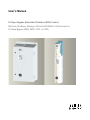
E-Clipse Bypass Embedded Fieldbus (EFB) Control
BACnet®, Modbus®, Metasys® N2 and APOGEE® FLN Protocols for
E-Clipse Bypass (BCR, BDR, VCR, or VDR)
ACH550 Drive Manuals
GENERAL MANUALS
ACH550-01/UH User's Manual
(0.75…90 kW) / (1…150 HP)
• Safety
• Installation
• Start-Up
• Diagnostics
• Maintenance
• Technical Data
ACH550-02/U2 User’s Manual
(110…355 kW) / (150…550 HP)
• Safety
• Installation
• Start-Up
• Diagnostics
• Maintenance
• Technical Data
ACH550 Technical Reference Manual
• Detailed Product Description
– Technical product description including dimensional
drawings
– Cabinet mounting information including power losses
– Software and control including complete parameter
descriptions
– User interfaces and control connections
– Complete options descriptions
– Spare parts
– Etc.
• Practical Engineering Guides
– PID & PFA engineering guides
– Dimensioning and sizing guidelines
– Diagnostics and maintenance information
– Etc.
ABB E-Clipse Bypass User’s Manual
(BSR, BDR, VCR, or VDR)
EAUA00000016461
• Safety
• Installation
• Start-Up
• Diagnostics
• Maintenance
• Technical Data
OPTION MANUALS
(Fieldbus Adapters, I/O Extension Modules etc., manuals
delivered with optional equipment)
Relay Output Extension Module (typical title)
• Installation
• Programming
• Fault tracing
• Technical data
APOGEE is a registered trademark of Siemens Building
Technologies Inc.
CANopen is a registered trademark of CAN in Automation
e.V.
ControlNet is a registered trademark of ControlNet
International.
DeviceNet is a registered trademark of Open DeviceNet
Vendor Association.
DRIVECOM is a registered trademark of DRIVECOM User
Organization.
Ethernet is a registered trademark of Xerox Corp.
Interbus is a registered trademark of Interbus Club.
LonWorks is a registered trademark of Echelon Corp.
Metasys is a registered trademark of Johnson Controls Inc.
Modbus and Modbus Plus are registered trademarks of
Schneider Automation Inc.
PROFIBUS is a registered trademark of Profibus Trade Org.
PROFIBUS DP is a registered trademark of Siemens AG.
ABB E-Clipse Bypass EFB User’s Manual
3
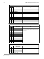
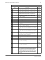
Table of Contents
Embedded Fieldbus
Overview . . . . . . . . . . . . . . . . . . . . . . . . . . . . . . . . . . . . . . . . . . . . . . . . . . . . . . 4
Planning . . . . . . . . . . . . . . . . . . . . . . . . . . . . . . . . . . . . . . . . . . . . . . . . . . . . . . . 5
Mechanical and Electrical Installation – EFB . . . . . . . . . . . . . . . . . . . . . . . . . . . 6
Communication Set-up Overview– EFB . . . . . . . . . . . . . . . . . . . . . . . . . . . . . . . 7
Serial Communication Selection . . . . . . . . . . . . . . . . . . . . . . . . . . . . . . . . . . . . 8
Serial Communication Configuration - Drive . . . . . . . . . . . . . . . . . . . . . . . . . . . 8
Serial Communication Configuration - Bypass . . . . . . . . . . . . . . . . . . . . . . . . . 11
Activate Drive Control Functions – EFB . . . . . . . . . . . . . . . . . . . . . . . . . . . . . . 13
Feedback from the Drive – EFB . . . . . . . . . . . . . . . . . . . . . . . . . . . . . . . . . . . . 17
Activate Bypass Control Functions – EFB . . . . . . . . . . . . . . . . . . . . . . . . . . . . 20
Feedback from the ABB E-Clipse Bypass EFB . . . . . . . . . . . . . . . . . . . . . . . . 23
Diagnostics – EFB . . . . . . . . . . . . . . . . . . . . . . . . . . . . . . . . . . . . . . . . . . . . . . 25
Serial Communication Diagnostics - Bypass . . . . . . . . . . . . . . . . . . . . . . . . . . 28
N2 Protocol Technical Data - System . . . . . . . . . . . . . . . . . . . . . . . . . . . . . . . 29
FLN Protocol Technical Data - System . . . . . . . . . . . . . . . . . . . . . . . . . . . . . . 43
BACnet Protocol Technical Data - System . . . . . . . . . . . . . . . . . . . . . . . . . . . . 64
Modbus Protocol Technical Data - System . . . . . . . . . . . . . . . . . . . . . . . . . . . 93
ABB Control Profiles Technical Data - Drive . . . . . . . . . . . . . . . . . . . . . . . . . 101
Table of Contents
4
ABB E-Clipse Bypass EFB User’s Manual
Embedded Fieldbus
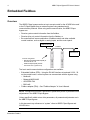
Overview
The ABB E-Clipse bypass can be set up to accept control for the ACH550 drive and/
or the E-Clipse Bypass from an external system using standard serial
communication protocols. When using serial communication, the ABB E-Clipse
bypass can:
• Receive system control information from the fieldbus,
• Receive drive only control information from the fieldbus, or
• Be controlled from some combination of fieldbus control and other available
control locations, such as digital or analog inputs, and the control panel.
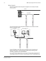
Fieldbus Controller
Fieldbus
Other Devices
Connect using either:
• Standard embedded fieldbus (EFB) at
terminals X2:26…30
• Fieldbus adapter (FBA) module
mounted in slot 1 (option Fxxx)
Two basic serial communications configurations are available:
• Embedded fieldbus (EFB) – Using the EIA 485 interface at terminals X2:26…30
on the control board, a control system can communicate with the bypass using:
– Modbus®
– Metasys® N2EIA 485
– APOGEE® FLN
– BACnet®
• Fieldbus adapter (FBA) – See "Fieldbus Adapter" in User’s Manual.
NOTE: Throughout this manual, references to parameters pertain to parameters and
adjustments in the ABB E-Clipse Bypass.
Unless specifically called-out as drive parameters, all parameter adjustments are in
the ABB E-Clipse bypass.
In this document any references to “system” refers to ABB E-Clipse Bypass and
ACH550 drive.
Embedded Fieldbus
ABB E-Clipse Bypass EFB User’s Manual
5
Control Interface
In general, the basic control interface between the fieldbus system and the bypass/
drive system consists of:
Protocol
Control Interface
Reference for more information
Modbus
• Output Words
– Control word
– Reference1
– Reference2
• Input Words
– Status word
– Actual value 1
– Actual value 2
– Actual value 3
– Actual value 4
– Actual value 5
– Actual value 6
– Actual value 7
– Actual value 8
The content of these words are defined by profiles.
For details on the profiles used, see
"Modbus Protocol Technical Data - System"
N2
•
•
•
•
Binary output objects
Analog output objects
Binary input objects
Analog input objects
"N2 Protocol Technical Data - System"
and
“N2 Protocol Technical Data - Bypass”
FLN
•
•
•
•
Binary output points
Analog output points
Binary input points
Analog input points
"FLN Protocol Technical Data - System"
and
“FLN Protocol Technical Data - Bypass”
BACnet
•
•
•
•
•
Device management
Binary output objects
Analog output objects
Binary input objects
Analog input objects
“BACnet Protocol Technical Data - "System
Overview"
Note! The words “output” and “input” are used as seen from the fieldbus controller
point of view. For example an output describes data flow from the fieldbus controller
to the bypass and appears as an input from the bypass point of view.
Planning
Network planning should address the following questions:
• What types and quantities of devices must be connected to the network?
• What control information must be sent to the system (drive only or system)?
• What feedback information must be sent from the bypass system to the
controlling system?
Embedded Fieldbus
6
ABB E-Clipse Bypass EFB User’s Manual
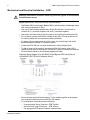
Mechanical and Electrical Installation – EFB
Warning! Connections should be made only while the bypass is disconnected
from the power source.
Bypass terminals 26…30 are for EIA 485 communications.
• Use Belden 9842 or equivalent. Belden 9842 is a dual twisted, shielded pair cable
with a wave impedance of 120 Ω.
• Use one of these twisted shielded pairs for the EIA 485 link. Use this pair to
connect all A (-) terminals together and all B (+) terminals together.
• Use both of the other wires in the other pair for the logical ground (terminal 29)
• Do not directly ground the EIA 485 network at any point. Ground all devices on
the network using their corresponding earthing terminals.
• As always, the grounding wires should not form any closed loops, and all the
devices should be earthed to a common ground.
• Connect the EIA 485 link in a daisy-chained bus, without dropout lines.
• To reduce noise on the network, terminate the EIA 485 network using 120 Ω
resistors at both ends of the network. Use the DIP switch to connect or disconnect
the termination resistors. See following diagram and table.
Preferred Wiring Diagram (See ACH550 E-Clipse Bypass EFB User’s Manual
(3AUA0000031267 REVA) for Alternate Wiring:
• Do not connect the shield at the bypass. Tie the shields together at the bypass.
Only load the shield connection at the EIA 485 master.
• For configuration information see the following:
– "Communication Set-up Overview– EFB" Section.
– "Activate Drive Control Functions – EFB" Section.
– The appropriate EFB protocol specific technical data.
Embedded Fieldbus
ABB E-Clipse Bypass EFB User’s Manual
7
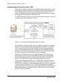
Communication Set-up Overview– EFB
The addition of serial communications to the ABB E-Clipse bypass system is done
by bringing the network connection to the bypass and using the bypass software to
direct messages either to the drive or to the bypass control software. The user
makes no connection to the drive fieldbus terminals since this channel is reserved
for the bypass control software’s control of the drive.
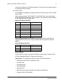
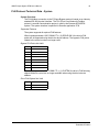
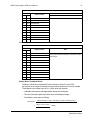
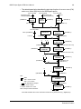
For all EFB Protocols, the drive is viewed as one node and the bypass is viewed as
a separate node. This is illustrated in Figure 1.
Figure 1 - Communications Physical and Logical Connections
Setup of the drive logical connection is done in parameter group 53 on the bypass
keypad. This group contains, among other things, the Drive MAC ID. Group 53 on
the drive must not be modified from the settings defined by the drive application
macro, 15 (Eclipse Bypass) since this will render the Internal MODBUS Interface
inoperable. Also, drive parameter 98.02, Protocol Sel must not be changed since
this will also render the Internal MODBUS Interface inoperable.
Selection of the EFB protocol is done in bypass parameter 98.02. Setup of the
bypass logical connection is done in parameter group 50 on the bypass keypad.
Certain parameters that control the network link are duplicated in group 50 and
group 53 (e.g. BAUD RATE) and are presented as read only in group 50.
The user can use bypass parameter 16.25, COMM CTRL to determine if control
signals (start and enables) go to the drive or to the system. Parameter 16.25 = 0
(DRIVE ONLY) is intended for legacy applications where the network was only able
to control the drive. Parameter 16.25 = 1 (SYSTEM) provides new functionality
where control signals control both the drive and bypass depending on the the drive/
bypass mode selected on the bypass keypad. In both cases, non-control related
points are visible on the bypass.
Embedded Fieldbus
8
ABB E-Clipse Bypass EFB User’s Manual
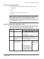
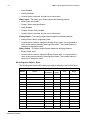
Serial Communication Selection
To activate the serial communication, set bypass parameter 9802 COMM PROT=
• 1 (STD MODBUS).
• 2 (N2)
• 3 (FLN)
• 4 (EXT FBA) - See External Fielbus Adapter User’s Manual
• 5 (BACNET)
Note! The bypass is the master for all serial communications. From the bypass
keypad, settings in Group 53 are used for the fieldbus communications to the drive.
From the bypass keypad, settings in Group 50 are used for the fieldbus
communicaitons to the bypass. When using serial communication diagnostics, only
the OK message counter & error message counter in the drive section (Group 53 on
the bypass keypad) will increment.
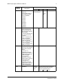
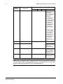
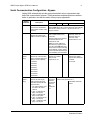
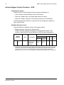
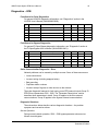
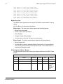
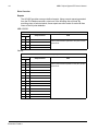
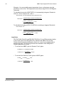
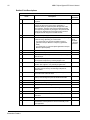
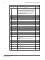
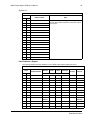
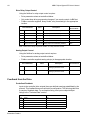
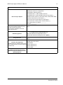
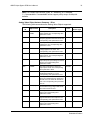
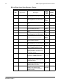
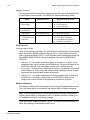
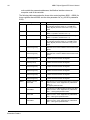
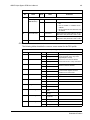
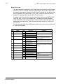
Serial Communication Configuration - Drive
Setting 9802 automatically sets the appropriate default values in parameters that
define the communication process. These parameters and descriptions are defined
below. In particular, note that the station Id may require adjustment.
Bypass
Parameter
Description
EFB Protocol Reference
Modbus
N2
FLN
BACnet
1625
COMM CONTROL
1625 = 0 (Drive Only)
for control signals (Start/Stop & enables) go to drive
only.
1625 = 1 (System)
for control signals to go to the system (drive or bypass,
depending on keypad mode selection)
5301
EFB PROTOCOL ID
Contains the identification
and program revision of
the protocol.
Do not edit. Any non-zero value entered for parameter
9802 COMM PROT SEL, sets this parameter
automatically. The format is: XXYY, where xx = protocol
ID, and YY = program revision.
5302
EFB STATION ID
Defines the drives node
address of the EIA 485
link.
Set each bypass on the network
with a unique value for this
parameter.
Default: 1
Note: For a new address to
take affect, the system power
must be cycled OR 5302 must
first be set to 0 before selecting
a new address. Leaving 5302 =
0 places the EIA 485 channel in
reset, disabling communication.
Embedded Fieldbus
Sets MS/TP MAC ID.
A temporary value of
0 places the protocol
channel in reset.
Default: 128
ABB E-Clipse Bypass EFB User’s Manual
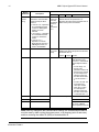
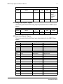
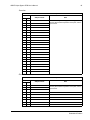
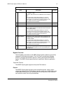
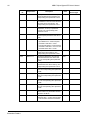
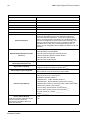
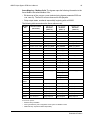
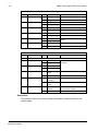
Bypass
Parameter
Description
9
EFB Protocol Reference
Modbus
N2
FLN
BACnet
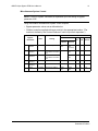
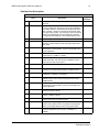
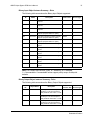
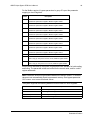
5303
EFB BAUD RATE
Defines the
communication speed of
the EIA 485 link in kbits
per second (kbits/s).
1.2 kbits/s
2.4 kbits/s
4.8 kbits/s
9.6 kbits/s
19.2 kbits/s
38.4 kbits/s
57.6 kbits/s
76.8 kbits/s
Default: 9.6
Do not edit for N2
5304
EFB PARITY
Defines the data length,
parity and stop bits to be
used with the EIA 485 link
communication.
• The same settings must
be used in all on-line
stations.
0 = 8N1 – 8 data bits, No
parity, one stop bit.
1 = 8N2 – 8 data bits, No
parity, two stop bits.
2 = 8E1 – 8 data bits, Even
parity, one stop bit.
3 = 8O1 – 8 data bits, Odd
parity, one stop bit.
Default:1
Default:0
5305
EFB CTRL PROFILE
Selects the communication
profile used by the EFB
protocol.
0 = ABB DRV LIM –
Operation of Control/
Status Words conform to
ABB bypass Profile, as
used in ACH400.
1 = DCU PROFILE –
Operation of Control/
Status Words conform to
32-bit DCU Profile.
2 = ABB DRV FULL –
Operation of Control/
Status Words conform to
ABB Bypass Profile, as
used in ACH600/800.
Default:1
Default:0
5310
EFB PAR10
Not used
for Comm
setup.
Sets the response turnaround time in
milliseconds. When this protocol is
selected, the default value is:
Default:
4.8
Do not
edit
Default: 38400
3 msec. 0 msec. 5 msec.
Embedded Fieldbus
10
ABB E-Clipse Bypass EFB User’s Manual
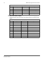
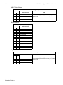
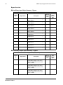
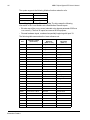
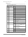
Bypass
Parameter
EFB Protocol Reference
Description
Modbus
N2
FLN
BACnet
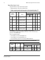
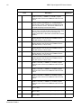
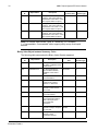
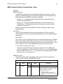
5311
EFB PAR11
Not used for Comm setup.
This parameter,
together with
parameter 5317, EFB
PAR 17, sets BACnet
Device Object
instance IDs:
• For the range 1 to
65,535: This
parameter sets the
ID directly (5317
must be 0). For
example, the
following values
set the ID to
49134: 5311 =
49134 and 5317 =
0.
• For IDs > 65,335:
The ID equals
5311’s value plus
10,000 times
5317’s value. For
example, the
following values
set the ID to
71234: 5311 =
1234 and 5317 =
7.
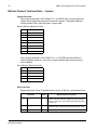
5314...5315
EFB PAR14... EFB PAR15
Not used for Comm setup.
Not Used
5316
EFB PAR16
5317
EFB PAR17
5318...5320
EFB PAR18...EFB PAR20
This parameter
indicates the count of
MS/TP tokens
passed to the unit
0
This parameter
works with parameter
5311 to set BACnet
instance IDs. See
parameter 5311.
N/A - Not supported
with BACnet protocol
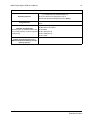
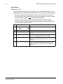
Note! After any changes to the communication settings, the communication channel
must be reset by either cycling the system power, or by clearing (set to 0 and enter)
and then restoring the station ID(5302) to desired station ID.
Embedded Fieldbus
ABB E-Clipse Bypass EFB User’s Manual
11
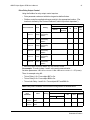
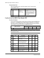
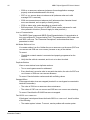
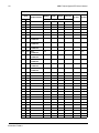
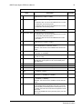
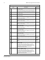
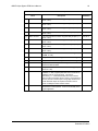
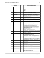
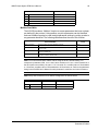
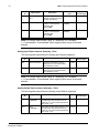
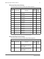
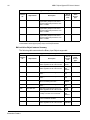
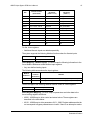
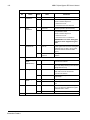
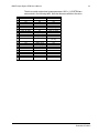
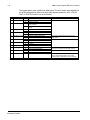
Serial Communication Configuration - Bypass
Setting 9802 automatically sets the appropriate default values in parameters that
define the communication process. These parameters and descriptions are defined
below. In particular, note that the station Id may require adjustment.
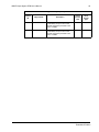
Bypass
Parameter
Description
EFB Protocol Reference
Modbus
N2
FLN
BACnet
5001
EFB PROTOCOL ID
Contains the identification
and program revision of the
protocol.
Do not edit. Any non-zero value entered for parameter
9802 COMM PROT SEL, sets this parameter automatically.
The format is: XXYY, where xx = protocol ID, and YY =
program revision.
5002
EFB STATION ID
Defines the bypass node
address of the EIA 485 link.
Set each bypass on the network
with a unique value for this
parameter.
When this protocol is selected,
the default value for this
parameter is: 256
Note: For a new address to
take affect, the bypass power
must be cycled OR 5002 must
first be set to 0 before selecting
a new address. Leaving 5002 =
0 places the EIA 485 channel in
reset, disabling communication.
Sets MS/TP MAC ID. A
temporary value of 0
places the protocol
channel in reset.
Default Value is: 129
5003
(Read
Only)
EFB BAUD RATE
Defines the communication
speed of the EIA 485 link in
kbits per second (kbits/s).
1.2 kbits/s
2.4 kbits/s
4.8 kbits/s
9.6 kbits/s
19.2 kbits/s
38.4 kbits/s
57.6 kbits/s
76.8 kbits/s
When this protocol is
selected, the default
value for this
parameter is: 9.6
When this protocol is
selected, the default
value for this parameter
is: 38900.
Do not edit.
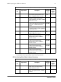
5004
(Read
Only)
EFB PARITY
Defines the data length,
parity and stop bits to be
used with the EIA 485 link
communication.
• The same settings must
be used in all on-line
stations.
0 = 8N1 – 8 data bits, No
parity, one stop bit.
1 = 8N2 – 8 data bits, No
parity, two stop bits.
2 = 8E1 – 8 data bits, Even
parity, one stop bit.
3 = 8O1 – 8 data bits, Odd
parity, one stop bit.
When this
protocol is
selected,
the default
value for
this
parameter
is: 1
4.8
When this protocol is selected, the default
value for this parameter is: 0
Sets MS/TP character
format.
Embedded Fieldbus
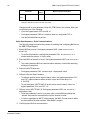
12
ABB E-Clipse Bypass EFB User’s Manual
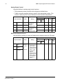
Bypass
Parameter
Description
EFB Protocol Reference
Modbus
N2
FLN
BACnet
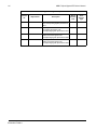
5005
(Read
Only)
EFB CTRL PROFILE
Selects the communication
profile used by the EFB
protocol.
0 = ABB DRV LIM – Operation
of Control/Status Words
conform to ABB bypass
Profile, as used in
ACH400.
1 = DCU PROFILE – Operation
of Control/Status Words
conform to 32-bit DCU
Profile.
2 = ABB DRV FULL –
Operation of Control/
Status Words conform to
ABB Bypass Profile, as
used in ACH600/800.
When this
protocol is
selected,
the default
value for
this
parameter
is: 0
N/A. When this protocol is selected, the
default value for this parameter is: 0.
Changing the value for this parameter has no
affect on this protocol’s behavior.
5010
EFB PAR10
Not used
for Comm
setup.
Sets them response turnaround time in
milliseconds. When this protocol is selected,
the default value is:
3 msec. 0 msec. 5 msec.
5011
EFB PAR11
Not used for Comm setup.
This parameter, together
with parameter 5317,
EFB PAR 17, sets BACnet
Device Object instance
IDs:
• For the range 1 to
65,535: This
parameter sets the ID
directly (5317 must be
0). For example, the
following values set
the ID to 49134: 5311
= 49134 and 5317 =
0.
• For IDs > 65,335: The
ID equals 5311’s
value plus 10,000
times 5317’s value.
For example, the
following values set
the ID to 71234: 5311
= 1234 and 5317 = 7.
5014
EFB PAR14
Not used for Comm setup.
Not Used
5016
EFB PAR15
Not Used
5017
EFB PAR17
This parameter indicates
the count of MS/TP
tokens passed to the unit
Note! After any changes to the communication settings, the communication channel
must be reset by either cycling the system power, or by clearing (set to 0 and enter)
and then restoring the station ID (5002) to desired station ID.
Embedded Fieldbus
ABB E-Clipse Bypass EFB User’s Manual
13
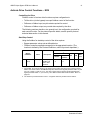
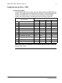
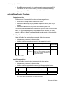
Activate Drive Control Functions – EFB
Controlling the Drive
Fieldbus control of various drive functions requires configuration to:
• Tell the drive (via the bypass) to accept fieldbus control of the function.
• Define as a fieldbus input, any drive data required for control.
• Define as a fieldbus output, any control data required by the drive.
The following sections describe, at a general level, the configuration required for
each control function. For the protocol-specific details, see the specific protocol
technical data section in this manual.
Start/Stop Control
Using the fieldbus for start/stop control of the drive requires:
• Bypass parameter values set as defined below.
• Fieldbus controller supplied command(s) in the appropriate location. (The
location is defined by the Protocol Reference, which is protocol dependent.)
Protocol Reference
Bypass
Parameter
Value
Description
Modbus1
ABB DRV
1601 START/
STOP
2 (COMM)
Start/Stop by
fieldbus with
Ext1or Ext2
selected.
40001 bits
0…3
DCU
PROFILE
40031 bits
0, 1
N2
BO1
FLN
24
BAC
net
BV10
1. For Modbus, the protocol reference can depend on the profile used, hence two columns in these
tables. One column refers to the ABB Drives profile, selected when bypass parameter 5305 = 0 (ABB
DRV LIM) or 5305 = 2 (ABB DRV FULL). The other column refers to the DCU profile selected when
bypass parameter 5305 = 1 (DCU PROFILE). See "ABB Control Profiles Technical Data - Drive" on
page 101.
2. The reference provides direction control – a negative reference provides reverse rotation.
Embedded Fieldbus
14
ABB E-Clipse Bypass EFB User’s Manual
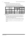
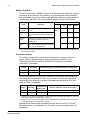
Input Reference Select
Using the fieldbus to provide input references to the drive requires:
• Drive parameter values set with the drive keypad as defined below.
• Fieldbus controller supplied reference word(s) in the appropriate location. (The
location is defined by the Protocol Reference, which is protocol dependent.)
Protocol Reference
Drive Parameter
Value
Setting
1102
EXT1/EXT2
SEL
8 (COMM)
Reference set
selection by
fieldbus.
1103
REF1 SEL
8 (COMM)
Input reference
1 by fieldbus.
1106
REF2 SEL
8 (COMM)
Input reference
2 by fieldbus.
Modbus
ABB DRV
DCU
PROFILE
40001 bit 11
40031 bit 5
N2
FLN
BAC
net
BO5
26
BV13
40002
AO1
60
AV16
40003
AO2
61
AV17
Reference Scaling
Where required, REFERENCES can be scaled. See the following, as appropriate:
• Modbus Register "40002" in the "With autobaud detection, once the proper baud
rate is detected, bypass parameter 5315 EFB PAR 15, shows the active baud
rate.Modbus Protocol Technical Data" section.
• "Reference Scaling" in the "ABB Control Profiles Technical Data - Drive" section.
• "N2 Analog Output Objects - Drive" in the "N2 Protocol Technical Data - System"
section.
• The slope of points 60 and 61 in the "FLN Protocol Technical Data - System"
section.
Embedded Fieldbus
ABB E-Clipse Bypass EFB User’s Manual
15
Drive Relay Output Control
Using the fieldbus for relay output control requires:
• Drive parameter values set with drive keypad as defined below.
• Fieldbus controller supplied reference word(s) in the appropriate location. (The
location is defined by the Protocol Reference, which is protocol dependent.)
Protocol Reference
Drive Parameter
Value
Modbus
Setting
ABB DRV
N2
DCU
PROFILE
FLN
BAC
net
1401
RELAY
OUTPUT
1
35
(COMM)
Relay Output 1
controlled by
fieldbus.
40134 bit 0 or 00033
BO7
40
BO0
1402
RELAY
OUTPUT
2
35
(COMM)
Relay Output 2
controlled by
fieldbus.
40134 bit 1 or 00034
BO8
41
BO1
1403
RELAY
OUTPUT
3
35
(COMM)
Relay Output 3
controlled by
fieldbus.
40134 bit 2 or 00035
BO9
42
BO2
RELAY
OUTPUT
4
35
(COMM)
Relay Output 4
controlled by
fieldbus.
40134 bit 3 or 00036
BO10
43
BO3
RELAY
OUTPUT
5
35
(COMM)
Relay Output 5
controlled by
fieldbus.
40134 bit 4 or 00037
BO11
44
BO4
RELAY
OUTPUT
6
35
(COMM)
Relay Output 6
controlled by
fieldbus.
40134 bit 5 or 00038
BO12
45
BO5
14101
14111
14121
1. More than 3 relays requires the addition of a relay extension module.
For example: To control relays 1 and 2 using serial communication:
Set drive parameters 1401 RELAY OUTPUT 1 and 1402 RELAY OUTPUT 1 = 35 (COMM).
Then, for example using N2:
• To turn Relay 1 On: Force object B07 to On.
• To turn Relay 2 On: Force object B08 to On.
• To turn both Relay 1 and 2 On: Force objects B07 and B08 On.
Note! Relay status feedback occurs without configuration as defined below.
Protocol Reference
Drive
Parameter
Value
Setting
Modbus
ABB DRV
0122 RO 1-3
STATUS
0123 RO 4-6
STATUS
DCU PROFILE
N2
FLN
BACnet
Relay 1…3
status.
40122
0122
BI4…BI6
76…78
BI0...BI2
Relay 4…6
status.
40123
0123
BI7…BI9
79…81
BI3...BI5
Embedded Fieldbus
16
ABB E-Clipse Bypass EFB User’s Manual
Analog Output Control
Using the fieldbus for analog output control requires:
• Drive parameter values set with the drive keypad as defined below.
• Fieldbus controller supplied reference word(s) in the appropriate location. (The
location is defined by the Protocol Reference, which is protocol dependent.)
Protocol Reference
Drive Parameter
Value
Setting
Modbus
ABB
DRV
1501 AO1 CONTENT
SEL
135 (COMM
VALUE 1)
0135 COMM VALUE 1
–
1507 AO2 CONTENT
136 (COMM
VALUE 2)
SEL
0136 COMM VALUE 2 –
Analog Output 1
controlled by
writing to
parameter 0135.
Analog Output 2
controlled by
writing to
parameter 0136.
N2
DCU
PROFILE
–
40135
–
40136
FLN
BAC
net
–
–
–
AO14
46
AO0
–
–
–
AO15
47
AO1
PID Control Setpoint Source
Use the following settings to select the fieldbus as the setpoint source for PID loops:
Protocol Reference
Drive Parameter
Value
Setting
Modbus
ABB
DRV
4010 SET POINT SEL
(Set 1)
4110
SET POINT SEL
(Set 2)
4210 SET POINT SEL
(Ext/Trim)
Embedded Fieldbus
8 (COMM
VALUE 1)
9 (COMM +
AI1)
10
(COMM*AI1)
Setpoint is either:
• Input Reference
2 (+/-/* AI1).
Control requires
parameter 1106
value = comm.
• Process PID
setpoint.
Control requires
parameter 1106
value = pid1 out
and parameter
4010 value =
comm.
DCU
PROFILE
40003
N2
AO2
FLN
61
BAC
net
AV17
ABB E-Clipse Bypass EFB User’s Manual
17
Feedback from the Drive – EFB
Pre-defined Feedback
Inputs to the controller (drive outputs) have pre-defined meanings established by the
protocol. This feedback does not require drive configuration. The following table lists
a sample of feedback data. For a complete listing, see input word/point/object
listings in the technical data for the appropriate protocol starting on page 88.
Drive Parameter
Protocol Reference
Modbus
N2
FLN
BACnet
0102
SPEED
40102
AI3
5
AV0
0103
FREQ OUTPUT
40103
AI1
2
AV1
0104
CURRENT
40104
AI4
6
AV4
0105
TORQUE
40105
AI5
7
AV5
0106
POWER
40106
AI6
8
AV6
0107
DC BUS VOLT
40107
AI11
13
AV2
0109
OUTPUT VOLTAGE
40109
AI12
14
AV3
0115
KWH COUNTER
40115
AI8
10
AV8
0118
DI1-3 STATUS – bit 1 (DI3)
40118
BI12
72
BI6
0122
RO1-3 STATUS
40122
BI4, BI5,
BI6
76, 77, 78
BI0
0301
FB STATUS WORD – bit 0 (STOP) 40301 bit 0
BI1
23
BV0
0301
FB STATUS WORD – bit 2 (REV)
BI2
21
BV1
40301 bit 2
Note! With Modbus, any parameter can be accessed using the format: 4 followed by
the parameter number.
Embedded Fieldbus
18
ABB E-Clipse Bypass EFB User’s Manual
Mailbox Read/Write
The ACH550 provides a “Mailbox” function to access parameters that have not been
pre-defined by the protocol. Using mailbox, any drive parameter can be identified
and read. Mailbox can also be used to adjust parameter settings by writing a value to
any parameter identified. The following table describes the use of this function.
Protocol Reference
Name
Description
Modbus
1
N2
FLN
BACnet
Mailbox
Parameter
Enter the number of the drive parameter to
access.
Does not AO19
apply.
95
AV25
Mailbox
Data
Contains the parameter value after a read,
or enter the desired parameter value for a
write.
AO20
96
AV26
Mailbox
Read
A binary value triggers a read – the value of
the “Mailbox Parameter” appears in
“Mailbox data”.
BO19
97
BV15
Mailbox
Write
A binary value triggers a write – the drive
value for the “Mailbox Parameter” changes
to the value in “Mailbox data”.
BO20
98
BV16
1. As noted above, Modbus provides direct access to all parameters using the format: 4 followed by
the parameter number.
Actual Value Scaling
The scaling of actual values can be protocol dependent. In general, for Actual
Values, scale the feedback integer using the parameter’s resolution. (See
"Parameter Descriptions" section in ACH550 User’s Manual for parameter
resolutions.) For example:
Feedback
Integer
Parameter
Resolution
(Feedback Integer) * (Parameter Resolution) = Scaled Value
1
0.1 mA
1 * 0.1 mA = 0.1 mA
10
0.1%
10 * 0.1% = 1%
Where parameters are in percent, the "Parameter Descriptions" section specifies
what parameter corresponds to 100%. In such cases, to convert from percent to
engineering units, multiply by the value of the parameter that defines 100% and
divide by 100%. For example:
Feedback
Integer
Parameter
Resolution
10
0.1%
100
0.1%
Value of the
Parameter that
defines 100%
1500 rpm1
500
Hz2
(Feedback Integer) * (Parameter Resolution) *
(Value of 100% Ref.) / 100% = Scaled Value
10 * 0.1% * 1500 RPM / 100% = 15 rpm
100 * 0.1% * 500 Hz / 100% = 50 Hz
1. Assuming, for the sake of this example, that the Actual Value uses parameter 9908 MOT NOM SPEED
as the 100% reference, and that 9908 = 1500 rpm.
2. Assuming, for the sake of this example, that the Actual Value uses parameter 9907 MOT NOM FREQ
as the 100% reference, and that 9907 = 500 Hz.
Although Actual Value scaling could differ from the above for the N2, FLN, and
BACnet protocols, it currently does not. To confirm, see the following sections, as
appropriate:
Embedded Fieldbus
ABB E-Clipse Bypass EFB User’s Manual
19
• "N2 Analog Input Objects - Bypass" in the "N2 Protocol Technical Data - System"
section.
• "Scaling Drive Feedback Values" in the "FLN Protocol Technical Data - System"
section.
Embedded Fieldbus
20
ABB E-Clipse Bypass EFB User’s Manual
Activate Bypass Control Functions – EFB
Controlling the bypass
Fieldbus control of various bypass functions requires configuration to:
• Tell the system to accept fieldbus control of the function.
• Define as a fieldbus input, any bypass data required for control.
• Define as a fieldbus output, any control data required by the drive/bypass.
The following sections describe, at a general level, the configuration required for
each control function.
Start/Stop Direction Control
Using the fieldbus for start/stop control of the bypass requires:
• Bypass parameter values set as defined below.
• Fieldbus controller supplied command(s) in the appropriate location. (The
location is defined by the Protocol Reference, which is protocol dependent.)
Protocol Reference
Bypass
Parameter
Value
Description
Modbus1
ABB DRV
1601 START/
STOP
2 (COMM)
Start/Stop by
fieldbus with
Ext1or Ext2
selected.
40001
bits 0…3
DCU
PROFILE
40031
bits 0, 1
N2
BO1
FLN
BACnet
24
BV10
1. For Modbus, the protocol reference can depend on the profile used, hence two columns in these
tables. One column refers to the ABB bypass profile, selected when parameter 5305 = 0 (ABB DRV
LIM) or 5305 = 2 (ABB DRV FULL). The other column refers to the DCU profile selected when
parameter 5305 = 1 (DCU PROFILE). See "ABB Control Profiles Technical Data - Drive" on page 101.
Embedded Fieldbus
ABB E-Clipse Bypass EFB User’s Manual
21
Miscellaneous System Control
NOTE: Control of system commands is dependent upon the setting of bypass
parameter 1625
Using the fieldbus miscellaneous system control requires:
• Bypass parameter values set as defined below.
• Fieldbus controller supplied reference word(s) in the appropriate location. (The
location is defined by the Protocol Reference, which is protocol dependent.)
Protocol Reference
Bypass
Parameter
Value
Modbus
Setting
ABB DRV
DCU
PROFILE
N2
FLN
BACnet
1602
RUN
ENABLE
2 (COMM)
Run enable by fieldbus
40001
bit 2
40031
bit 6
(inverted)
BO2
35
BV12
1603
START
ENABLE 1
2 (COMM)
Source for start enable 1
is the fieldbus Command
word
N/A
40032
bit 2
BO10
50
BV15
1604
START
ENABLE 2
2 (COMM)
Source for start enable 2
is the fieldbus Command
word
40032
bit 3
BO11
51
BV16
1605
START
ENABLE 3
2 (COMM)
N/A
N/A
BO12
52
BV17
1606
START
ENABLE 4
2 (COMM)
N/A
N/A
BO13
53
BV18
1607
START
RESET SEL
2 (COMM)
40001
bit 7
40031
bit4
BO3
94
BV14
Fault reset by fieldbus.
Embedded Fieldbus
22
ABB E-Clipse Bypass EFB User’s Manual
Bypass Relay Output Control
Using the fieldbus for relay output control requires:
• Bypass parameter values set as defined below.
• Fieldbus controller supplied reference word(s) in the appropriate location. (The
location is defined by the Protocol Reference, which is protocol dependent.)
Protocol Reference
Bypass
Parameter
Value
Modbus
Setting
ABB DRV
N2
DCU
PROFILE
FLN
BACnet
1401
RELAY
OUTPUT
1
16
(COMM
CTRL)
Relay Output 1
controlled by fieldbus.
40134 bit 0 or 00033 BO5
40
BO0
1404
RELAY
OUTPUT
2
16
(COMM
CTRL)
Relay Output 2
controlled by fieldbus.
40134 bit 1 or 00034 BO6
41
BO1
1407
RELAY
OUTPUT
3
16
(COMM
CTRL)
Relay Output 3
controlled by fieldbus.
40134 bit 2 or 00035 BO7
42
BO2
1410
RELAY
OUTPUT
4
16
(COMM
CTRL)
Relay Output 4
controlled by fieldbus.
40134 bit 3 or 00036 BO8
43
BO3
1413
RELAY
OUTPUT
5
16
(COMM
CTRL)
Relay Output 5
controlled by fieldbus.
40134 bit 4 or 00037
44
BO4
BO9
For example: To control relays 1 and 2 using serial communication:
From the bypass keypad, set parameters 1401 RELAY OUTPUT 1 and 1402 RELAY
OUTPUT 2 = 16 (COMM CTRL).
Then, for example using N2:
• To turn Relay 1 On: Force object B05 to On.
• To turn Relay 2 On: Force object B06 to On.
• To turn both Relay 1 and 2 On: Force objects B05 and B06 On.
Note! Relay status feedback occurs without configuration as defined below.
Protocol Reference
Bypass
Parameter
Value
Setting
Modbus
ABB DRV
0122 RO 1-3
STATUS
0123 RO 4-5
STATUS
Embedded Fieldbus
DCU PROFILE
N2
FLN
BACnet
Relay 1…3
status.
40122
0122
BI16..
BI18
76…
78
BI0…
BI2
Relay 4…5
status.
40123
0123
BI19..
BI20
79…
80
BI3…
BI4
ABB E-Clipse Bypass EFB User’s Manual
23
Communication Fault
When using fieldbus control, specify the bypass’ action if external serial
communication is lost.
Bypass Parameter
Value
Description
3004 COMM FAULT FUNC
0 (NOT SEL)
1 (FAULT)
2 (CONST SP7)
3 (LAST SPEED)
3005 COMM FAULT TIME
Set time delay before acting on a communication loss.
Set for appropriate drive/bypass
response.
NOTE: If the system is in bypass
mode when communication is lost,
choices 2 and 3 will cause the
bypass contactor to remain in it’s
present state.
Feedback from the ABB E-Clipse Bypass EFB
Pre-defined Feedback
Inputs to the controller (bypass outputs) have pre-defined meanings established by
the protocol. This feedback does not require bypass configuration. The following
table lists a sample of feedback data. For a complete listing, see input word/point/
object listings in the technical data for the appropriate protocol.
Protocol Reference
Bypass Parameter
0101
Modbus
MOTOR CURR
40101
N2
AI1
FLN
6
BACnet
AV0
Note! With Modbus, any parameter can be accessed using the format: 4 followed by
the parameter number.
Type
Name
Description
N2
FLN
BACnet
DI
System Ready
System is ready to accept start
command (either mode).
BI1
27
BV7
DI
System
Enabled
System is enabled to start motor
(either mode).
BI2
34
BV9
DI
System Started
System start enables are made
and start command has been
received (either mode). Motor
runs if run enable is active.
BI3
28
BV1
BI4
23
BV0
DI
System
Running
Motor is running (either mode).
DI
Fieldbus Local
System is under fieldbus local
control (either mode).
BI5
36
N/A
DI
Bypass Fault
Bypass is faulted.
BI6
93
BV2
DI
Bypass Alarm
Bypass is alarming.
BI7
86
BV5
DI
Comm Control
System is configured for control in
the comm channel
BI8
37
Embedded Fieldbus
24
ABB E-Clipse Bypass EFB User’s Manual
Type
Name
Description
N2
FLN
BACnet
BI9
25
BV13
DI
Bypass
Override
Bypass override 2 status
DI
DI1 Status
Bypass digital input 1 status
BI10
70
BI5
DI
DI2 Status
Bypass digital input 2 status
BI11
71
BI6
DI
DI3 Status
Bypass digital input 3 status
BI12
72
BI7
DI
DI4 Status
Bypass digital input 4 status
BI13
73
BI8
DI
DI5 Status
Bypass digital input 5 status
BI14
74
BI9
DI
DI6 Status
Bypass digital input 6 status
BI15
75
BI10
DI
RO1 Status
Bypass relay output 1 status
BI16
76
BI0
DI
RO2 Status
Bypass relay output 2 status
BI17
77
BI1
DI
RO3 Status
Bypass relay output 3 status
BI18
78
BI2
DI
RO4 Status
Bypass relay output 4 status
BI19
79
BI3
DI
RO5 Status
Bypass relay output 5 status
BI20
80
BI4
DI
Bypass Select
1=Bypass mode, 0=Drive mode
BI21
32
BV4
DI
System
Underload
Reports system underload status
(either mode)
BI22
7
BV8
DI
System Fault
Reports system fault status (either
mode)
BI23
93
BV3
DI
Bypass Run
Reports motor running status in
bypass mode
BI24
33
BV6
Embedded Fieldbus
ABB E-Clipse Bypass EFB User’s Manual
25
Diagnostics – EFB
Fault Queue for Drive Diagnostics
For general ACH550 diagnostics information, see “Diagnostics” section in the
ACH550 User’s Manual (3AUA0000004092).
Type
Name
Description
Modbus
N2
FLN
BACnet
AI
Last Fault
Reports last drive fault
40401
AI17
90
AV18
AI
Previous Fault
Reports fault previous to last
40402
AI18
91
AV19
AI
Oldest Fault
Reports third-oldest fault
40403
AI19
92
AV20
AI
Alarm Word 1
Reports alarm word 1
N/A
88
N/A
AI
Alarm Word 2
Reports alarm word 2
N/A
89
N/A
Fault Queue for Bypass Diagnostics
For general E-Clipse Bypass diagnostics information, see “Diagnostics” section in
the E-Clipse Bypass User’s Manual (3AUA0000016461).
Type
Name
Description
Modbus
N2
FLN
BACnet
AI
Last Fault
Reports last drive fault
40401
AI2
90
AV3
AI
Previous Fault
Reports fault previous to last
40402
N/A
N/A
N/A
AI
Oldest Fault
Reports third-oldest fault
40403
N/A
N/A
N/A
AI
Alarm Word 1
Reports alarm word 1
AI3
88
AV4
AI
Alarm Word 2
Reports alarm word 2
AI4
89
AV5
Serial Communication Diagnostics - Drive
Network problems can be caused by multiple sources. Some of these sources are:
• Loose connections
• Incorrect wiring (including swapped wires)
• Bad grounding
• Duplicate station numbers
• Incorrect setup of bypass or other devices on the network
The major diagnostic features for fault tracing on an EFB network include Group 53
EFB Protocol parameters 5306…5309. The "Parameter Descriptions" section
describes these parameters in detail. Group 53 applies to the drive external
communications. Group 50 applies to the bypass external communications.
Diagnostic Situations
The sub-sections below describe various diagnostic situations – the problem
symptoms and corrective actions.
Normal Operation
During normal network operation, 5306…5309 bypass parameter values act as
follows at each bypass:
Embedded Fieldbus
26
ABB E-Clipse Bypass EFB User’s Manual
• 5306 DV OK MESSAGES advances (advances for each application message
properly received and addressed to this drive).
• 5307 DV CRC ERRORS does not advance at all (advances when an invalid
message CRC is received).
• 5308 UART ERRORS does not advance at all (advances when character format
errors are detected, such as parity or framing errors).
• 5309 DV status value varies depending on network traffic.
• BACnet protocol: 5316 EFB PAR 16 (MS/TP token counter) advances for each
token passed to this drive. (Does not apply for other protocols.)
Loss of Communication
The ABB E-Clipse bypass and ABB E-Clipse Bypass behavior, if communication is
lost, was configured in "Communication Fault". The parameters are 3004 COMM LOSS
and 3005 COMM TIME. The "Parameter Descriptions" section describes these
parameters in detail.
No Master Station on Line
If no master station is on line: Neither the EFB OK MESSAGES nor the errors (5307 EFB
and 5308 EFB UART ERRORS) increase on any of the stations.
CRC ERRORS
To correct:
• Check that a network master is connected and properly programmed on the
network.
• Verify that the cable is connected, and is not cut or short circuited.
Duplicate Stations
If two or more stations have duplicate numbers:
• Two or more bypass cannot be addressed.
• Every time there is a read or write to one particular station, the value for 5307 EFB
CRC ERRORS or 5308 EFB UART ERRORS advances.
To correct: Check all station numbers and edit conflicting values.
Swapped Wires
If the communication wires are swapped (terminal A on one bypass is connected to
terminal B on another):
• The value of 5306 EFB OK MESSAGES does not advance.
• The values of 5307 EFB CRC ERRORS and 5308 EFB UART ERRORS are advancing.
To correct: Check that the EIA 485 lines are not swapped.
Fault 3028 – EXT COMM LOSS
If the bypass’ control panel shows fault code 3028 “EXT COMM LOSS”, check for either
of the following:
• The master system is down. To correct, resolve problem with master system.
Embedded Fieldbus
ABB E-Clipse Bypass EFB User’s Manual
27
• The communication connection is bad. To correct, check communication
connection at the bypass.
• The time-out selection for the bypass is too short for the given installation. The
master is not polling the bypass within the specified time-out delay. To correct,
increase the time set by parameter 3005 COMM TIME.
Embedded Fieldbus
28
ABB E-Clipse Bypass EFB User’s Manual
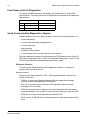
Fault Queue for Drive Diagnostics
For general ACH550 diagnostics information, see “Diagnostics” in the ACH550
User’s Manual. The three most recent ACH550 faults are reported to the fieldbus as
defined below.
Drive Parameter
BACnet Access Point
0401 Last Fault
AV18
0412 Previous Fault 1
AV19
0413 Previous Fault 2
AV20
Serial Communication Diagnostics - Bypass
Network problems can be caused by multiple sources. Some of these sources are:
• Loose connections
• Incorrect wiring (including swapped wires)
• Incorrect baud rate
• Bad grounding
• Duplicate station numbers
• Incorrect setup of drives or other devices on the network
The major diagnostic features for fault tracing on an EFB network include Group 50
EFB Protocol parameters 5006…5009. The “Parameter Descriptions” section, in the
ACH550 User’s Manual, describes these parameters in detail.
Diagnostic Situations
The sub-sections below describe various diagnostic situations – the problem
symptoms and corrective actions.
Normal Operation
During normal network operation, 5006…5009 bypass parameter values act as
follows at each drive:
• 5006 BP OK MESSAGES advances (advances for each application message
properly received and addressed to this bypass).
• 5007 BP CRC ERRORS does not advance at all (advances when an invalid
message CRC is received).
• 5008 UART ERRORS does not advance at all (advances when character format
errors are detected, such as parity or framing errors). Read only copy from 5308.
• 5009 BP STATUS value varies depending on network traffic.
• 5016 EFB PAR 16 (MS/TP token counter) advances for each token passed to this
drive.
Embedded Fieldbus
ABB E-Clipse Bypass EFB User’s Manual
29
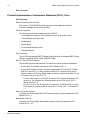
N2 Protocol Technical Data - System
System Overview
The N2 Fieldbus connection to the system is based on an industry standard RS-485
physical interface. The N2 Fieldbus protocol is a master-slave type, serial
communication protocol, used by the Johnson Controls Metasys® system. In the
Metasys architecture the N2 Fieldbus connects object interfaces and remote
controllers to Network Control Units (NCUs).
The N2 Fieldbus can also be used to connect the system to the Metasys Companion
product line.
This section describes the use of the N2 Fieldbus with the E-Clipse Bypass
connection.
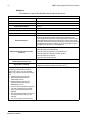
Supported Features
In the N2 Fieldbus protocol the ACH550 and E-Clipse Bypass may appear as a
“virtual object”.
Metasys
Analog Inputs
Binary Inputs
Virtual Object
Analog Outputs
ACH550
Binary Outputs
Internal values, Float, Integer, Byte
Metasys
Analog Inputs
Binary Inputs
Virtual Object
Analog Outputs
E-Clipse Bypass
Binary Outputs
Note: Metasys inputs are drive outputs and drive inputs
are Metasys ouputs
Internal values, Float, Integer, Byte
A virtual object is made up of:
• Analog Inputs
• Binary Inputs
• Analog Outputs
• Binary Outputs
Internal values for Floating point, Integer, and Byte values.
Embedded Fieldbus
30
ABB E-Clipse Bypass EFB User’s Manual
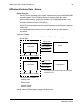
Metasys Integration
The following diagram shows the system’s integration to the Johnson Controls
Metasys system.
N1LAN
NCU
N2 Fieldbus
The following diagram shows the system’s integration to the Johnson Controls
Metasys Companion system.
PC-Version
PC Version
Panel Version/LTD
Panel
Version/LTD
Converter Converter
RS232 -RS485
N2 Fieldbus
On the N2 Fieldbus each system can be accessed by the full complement of
Metasys FMS features, including Change-of-State (COS) monitoring, alarm
notification, scheduling, trend, and totalization.
On one N2 Fieldbus segment there can be up to 32 nodes while integrating the EClipse Bypass system with Johnson Controls Metasys. Each E-Clipse bypass may
Embedded Fieldbus
ABB E-Clipse Bypass EFB User’s Manual
31
consume two nodes on a N2 fieldbus segment. If both the drive and bypass objects
are being polled by the system.
Drive Device Type
For the Metasys and Metasys Companion products, the device type for the ACH550
drive is VND.
When bypass parameter 1625 COMM CTL= (0) DRIVE ONLY, drive’s N2 objects
are all supported using the drive’s device address. The bypass’s N2 objects related
to the control word are no longer valid.
Bypass N2 Objects Not Valid
Number
Object
Bypass Parameter
BO1
SYSTEM START
Command Word
BO2
SYSTEM DISABLE
Command Word
BO3
SYSTEM RESET
Command Word
BO4
OVERRIDE
Command Word
B10
START ENABLE 1
Command Word
B11
START ENABLE 2
Command Word
B12
START ENABLE 3
Command Word
B13
START ENABLE 4
Command Word
When bypass parameter 1625 COMM CTL= (1) SYSTEM, drive’s N2 following
objects related to control are no longer available when using the drive’s device
address.
Drive N2 Objects Not Valid
Number
Object
Bypass Parameter
BO1
START/STOP
Command Word
BO2
RUN ENABLE
Command Word
BO3
N2 LOCAL CTL
Command Word
Drive Overview
The ACH550 drive does not support N2 Fieldbus communication “internal values”.
All of the Analog and Binary I/O objects are listed below.
Analog Input – The analog input objects support the following features:
• Analog Input actual value in engineering units
• Low Alarm limit
• Low Warning limit
• High Warning limit
• High Alarm limit
• Differential value for the hysteresis of the Alarms and Warnings
• Change of State (COS) enabled
Embedded Fieldbus
32
ABB E-Clipse Bypass EFB User’s Manual
• Alarm Enabled
• Warning Enabled
• Override value is received, but there is no action taken.
Binary Input – The binary input objects support the following features:
• Binary Input actual value
• Normal / Alarm state specification
• Alarm Enabled
• Change of State (COS) enabled
• Override value is received, but there is no action taken.
Analog Output – The analog output objects support the following features:
• Analog Output value in engineering units
• Override value is used to change the Analog Output value. It is not possible to
return to the previous value by removing the override. The override feature is
used only to change the value.
Binary Output – The binary output objects support the following features:
• Binary Output value
• Override value is used to change the Binary Output value. It is not possible to
return to the previous value by removing the override. The override feature is
used only to change the value.
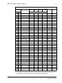
N2 Analog Input Objects - Drive
The following table lists the N2 Analog Input objects defined for the ACH550 drive.
N2 Analog Inputs:
Number
Object
Drive
Parameter
Scale
Factor
Units
Range
AI1
OUTPUT FREQUENCY
0103
10
Hz
0…250
AI2
RATED SPEED
Note 1
10
%
0 …100
AI3
SPEED
0102
1
rpm
0 …9999
AI4
CURRENT
0104
10
A
0…9999
AI5
TORQUE
0105
10
%
-200…200
AI6
POWER
0106
10
kW
0…65,535
AI7
DRIVE TEMPERATURE
0110
10
°C
0 …125
AI8
KILOWATT HOURS
0115
1
kWh
0…65,535
AI9
MEGAWATT HOURS
0141
1
MWh
0…65,535
AI10
RUN TIME
0114
1
H
0…65,535
AI11
DC BUS VOLTAGE
0107
1
V
0…999
AI12
OUTPUT VOLTAGE
0109
1
V
0…999
AI13
PRC PID FEEDBACK
0130
10
%
0…100
AI14
PRC PID DEVIATION
0132
10
%
0…100
Embedded Fieldbus
ABB E-Clipse Bypass EFB User’s Manual
33
N2 Analog Inputs:
Number
Object
Drive
Parameter
Scale
Factor
Units
Range
AI15
EXT PID FEEDBACK
0131
10
%
0…100
AI16
EXT PID DEVIATION
0133
10
%
0…100
AI17
LAST FAULT
0401
1
fault code
AI18
PREV FAULT
0402
1
fault code
AI19
OLDEST FAULT
0403
1
fault code
AI20
AI 1 ACTUAL
0120
10
%
0…100
AI21
AI 2 ACTUAL
0121
10
%
0…100
AI22
AO 1 ACTUAL
0124
10
mA
0…20
AI23
AO 2 ACTUAL
0125
10
mA
0…20
AI24
MOTOR TEMP
0145
1
°C
0…200
AI25
REVOLUTION CNT
0142
1
MREV
0…32767
1. RATED SPEED is a percent of maximum frequency (parameter 2008) if the drive is in scalar mode,
and is a percent of maximum speed (parameter 2002) in speed mode.
N2 Binary Input Objects - Drive
The following table lists the N2 Binary Input objects defined for the ACH550 drive.
N2 Binary Inputs:
Number
Object
Drive Parameter
Range
BI1
STOP/RUN
Status Word
0 = Stop, 1 = Drive Running
BI2
FORWARD/REVERSE
Status Word
0 = Forward, 1 = Reverse
BI3
FAULT STATUS
Status Word
0 = OK, 1 = Drive Fault
BI4
RELAY 1 STATUS
0122 (bit mask 04)
0 = Off, 1 = On
BI5
RELAY 2 STATUS
0122 (bit mask 02)
0 = Off, 1 = On
BI6
RELAY 3 STATUS
0122 (bit mask 01)
0 = Off, 1 = On
BI7
RELAY 4 STATUS
0123 (bit mask 04)
0 = Off, 1 = On
BI8
RELAY 5 STATUS
0123 (bit mask 02)
0 = Off, 1 = On
BI9
RELAY 6 STATUS
0123 (bit mask 01)
0 = Off, 1 = On
BI10
INPUT 1 STATUS
0118 (bit mask 04)
0 = Off, 1 = On
BI11
INPUT 2 STATUS
0118 (bit mask 02)
0 = Off, 1 = On
BI12
INPUT 3 STATUS
0118 (bit mask 01)
0 = Off, 1 = On
BI13
INPUT 4 STATUS
0119 (bit mask 04)
0 = Off, 1 = On
BI14
INPUT 5 STATUS
0119 (bit mask 02)
0 = Off, 1 = On
BI15
INPUT 6 STATUS
0119 (bit mask 01)
0 = Off, 1 = On
BI16
EXTERNAL 2 SELECT
Status Word
0 = EXT1 = EXT2
BI17
HAND/AUTO
Status Word
0 = AUTO, 1 = HAND
BI18
ALARM
Status Word
0 = OK, 1 = ALARM
BI19
MAINTENANCE REQ
Status Word
0 = OK, 1 = MAINT REQ
BI20
DRIVE READY
Status Word
0 = Not Ready, 1 = Ready
Embedded Fieldbus
34
ABB E-Clipse Bypass EFB User’s Manual
N2 Binary Inputs:
Number
Object
Drive Parameter
Range
BI21
AT SETPOINT
Status Word
0 = No, 1 = At Setpoint
BI22
RUN ENABLED
Status Word
0 = Not Enabled, 1 = Enabled
BI23
N2 LOCAL MODE
Status Word
0 = Auto, 1 = N2 Local
BI24
N2 CONTROL SRC
Status Word
0 = No, 1 = Yes
BI25
N2 REF1 SRC
Status Word
0 = No, 1 = Yes
BI26
N2 REF2 SRC
Status Word
0 = No, 1 = Yes
N2 Analog Output Objects - Drive
The following table lists the N2 Analog Output objects defined for the ACH550 drive.
N2 Analog Outputs:
Number
Object
Drive
Parameter
Scale
Factor
Units
Range
AO1
REFERENCE 1
Reference 1
10
%
0…100
AO2
REFERENCE 2
Reference 2
10
%
0…100
AO3
ACCEL TIME 1
2202
10
s
0.1…1800
AO4
DECEL TIME 1
2203
10
s
0.1…1800
AO5
CURRENT LIMIT
2003
10
A
0…1.3*I2N
AO6
PID1-CONT GAIN
4001
10
%
0.1…100
AO7
PID1-CONT I-TIME
4002
10
s
0.1…600
AO8
PID1-CONT D-TIME
4003
10
s
0…10
AO9
PID1-CONT D FILTER
4004
10
s
0…10
AO10
PID2-CONT GAIN
4101
10
%
0.1…100
AO11
PID2-CONT I-TIME
4102
10
s
0.1…600
AO12
PID2-CONT D-TIME
4103
10
s
0…10
AO13
PID2-CONT D FILTER
4104
10
s
0…10
AO14
COMMAND AO 1
135
10
%
0…100
AO15
COMMAND AO 2
136
10
%
0…100
AO16
EXT PID SETPOINT
4211
10
%
0…100
AO17
SPD OUT MIN
2001/2007
10
%
0…200
AO18
SPD OUT MAX
2002/2008
10
%
0…200
A019
MAILBOX PARAMETER
1
0…65535
A020
MAILBOX DATA
1
0…65535
Embedded Fieldbus
ABB E-Clipse Bypass EFB User’s Manual
35
N2 Binary Output Objects - Drive
The following table lists the N2 Binary Output objects defined for the ACH550 drive.
N2 Binary Outputs:
Number
Object
Drive Parameter
Range
BO1
STOP/START
Command Word
0 = Stop, 1 = Start to Speed
BO2
FORWARD/REVERSE
Command Word
0 = Forward, 1 = Reverse
BO3
PANEL LOCK
Command Word
0 = Open, 1 = Locked
BO4
RUN ENABLE
Command Word
0 = Enable, 1 = Disable
BO5
REF1/REF2 SELECT
Command Word
0 = Ref1, 1 = Ref2
BO6
FAULT RESET
Command Word
Change 0 -> 1 Resets
BO7
COMMAND RO 1
134 (bit mask 01)
0 = Off, 1 = On
BO8
COMMAND RO 2
134 (bit mask 02)
0 = Off, 1 = On
BO9
COMMAND RO 3
134 (bit mask 04)
0 = Off, 1 = On
BO10
COMMAND RO 4
134 (bit mask 08)
0 = Off, 1 = On
BO11
COMMAND RO 5
134 (bit mask 10)
0 = Off, 1 = On
BO12
COMMAND RO 6
134 (bit mask 20)
0 = Off, 1 = On
BO13
RESET RUN TIME
114 (indirectly)
0 = N/A, 1 = On (Reset Run Time)
BO14
RESET KWH COUNT
115 (indirectly)
0 = N/A, 1 = On (Reset kWh Count)
BO15
PRC PID SELECT
4027 (indirectly)
0 = SET2, 1 = SET2
BO16
N2 LOCAL CTL (Note 1)
Command Word
0 = Auto, 1 = N2
BO17
N2 LOCAL REF (Note 1)
Command Word
0 = Auto, 1 = N2
BO18
SAVE PARAMETERS
1607 (indirectly)
0 = N/A, 1 = On (Save Parameters)
B019
READ MAILBOX
0 = No, 1 = Yes
B020
WRITE MAILBOX
0 = No, 1 = Yes
1. N2 LOCAL CTL and N2 LOCAL REF have priority over drive input terminals. Use these binary
outputs for temporary N2 control of the drive when COMM is not the selected control source.
Embedded Fieldbus
36
ABB E-Clipse Bypass EFB User’s Manual
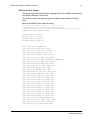
DDL File for NCU - Drive
The listing below is the Data Definition Language (DDL) file for ACH550 drives used
with the Network Control Units.
This listing is useful when defining drive I/O objects to the Network Controller Units.
Below is the ACH550.DDL file listing.
*******************************************************************
* ABB Drives, ACH 550 Variable Frequency Drive
*******************************************************************
CSMODEL "ACH_550","VND"
AITITLE
BITITLE
AOTITLE
BOTITLE
"Analog_Inputs"
"Binary_Inputs"
"Analog_Outputs"
"Binary_Outputs"
CSAI
CSAI
CSAI
CSAI
CSAI
CSAI
CSAI
CSAI
CSAI
CSAI
CSAI
CSAI
CSAI
CSAI
CSAI
CSAI
CSAI
CSAI
CSAI
CSAI
CSAI
CSAI
CSAI
CSAI
CSAI
"AI1",N,N,"FREQ_ACT","Hz"
"AI2",N,N,"PCT_ACT","%"
"AI3",N,N,"SPEED","RPM"
"AI4",N,N,"CURRENT","A"
"AI5",N,N,"TORQUE","%"
"AI6",N,N,"POWER","kW"
"AI7",N,N,"DRV_TEMP","°C"
"AI8",N,N,"ENERGY_k","kWh"
"AI9",N,N,"ENERGY_M","MWh"
"AI10",N,N,"RUN_TIME","H"
"AI11",N,N,"DC_VOLT","V"
"AI12",N,N,"VOLT_ACT","V"
"AI13",N,N,"PID1_ACT","%"
"AI14",N,N,"PID2_DEV","%"
"AI15",N,N,"PID2_ACT","%"
"AI16",N,N,"PID2_DEV","%"
"AI17",N,N,"LAST_FLT","Code"
"AI18",N,N,"PREV_FLT","Code"
"AI19",N,N,"1ST_FLT","Code"
"AI20",N,N,"AI_1_ACT","%"
"AI21",N,N,"AI_2_ACT","%"
"AI22",N,N,"AO_1_ACT","mA"
"AI23",N,N,"AO_2_ACT","mA"
"AI24",N,N,"MTR_TEMP","°C"
"AI25",N,N,"REVL_CNT",""
CSBI
CSBI
CSBI
CSBI
CSBI
CSBI
CSBI
"BI1",N,N,"STOP/RUN","STOP","RUN"
"BI2",N,N,"FWD/REV","FWD","REV"
"BI3",N,N,"FAULT","OK","FLT"
"BI4",N,N,"RELAY_1","OFF","ON"
"BI5",N,N,"RELAY_2","OFF","ON"
"BI6",N,N,"RELAY_3","OFF","ON"
"BI7",N,N,"RELAY_4","OFF","ON"
Embedded Fieldbus
ABB E-Clipse Bypass EFB User’s Manual
CSBI
CSBI
CSBI
CSBI
CSBI
CSBI
CSBI
CSBI
CSBI
CSBI
CSBI
CSBI
CSBI
CSBI
CSBI
CSBI
CSBI
CSBI
CSBI
CSAO
CSAO
CSAO
CSAO
CSAO
CSAO
CSAO
CSAO
CSAO
CSAO
CSAO
CSAO
CSAO
CSAO
CSAO
CSAO
CSAO
CSAO
CSAO
CSAO
CSBO
CSBO
CSBO
CSBO
CSBO
CSBO
CSBO
CSBO
CSBO
CSBO
CSBO
37
"BI8",N,N,"RELAY_5","OFF","ON"
"BI9",N,N,"RELAY_6","OFF","ON"
"BI10",N,N,"INPUT_1","OFF","ON"
"BI11",N,N,"INPUT_2","OFF","ON"
"BI12",N,N,"INPUT_3","OFF","ON"
"BI13",N,N,"INPUT_4","OFF","ON"
"BI14",N,N,"INPUT_5","OFF","ON"
"BI15",N,N,"INPUT_6","OFF","ON"
"BI16",N,N,"EXT1/2","EXT1","EXT2"
"BI17",N,N,"HND/AUTO","HAND","AUTO"
"BI18",N,N,"ALARM","OFF","ON"
"BI19",N,N,"MNTNCE_R","OFF","ON"
"BI20",N,N,"DRV_REDY","NO","YES"
"BI21",N,N,"AT_SETPT","NO","YES"
"BI22",N,N,"RUN_ENAB","NO","YES"
"BI23",N,N,"N2_LOC_M","AUTO","N2_L"
"BI24",N,N,"N2_CTRL","NO","YES"
"BI25",N,N,"N2_R1SRC","NO","YES"
"BI26",N,N,"N2_R2SRC","NO","YES"
"AO1",Y,Y,"REF_1","%"
"AO2",Y,Y,"REF_2","%"
"AO3",Y,Y,"ACCEL_1","s"
"AO4",Y,Y,"DECEL_1","s"
"AO5",Y,Y,"CURR_LIM","A"
"AO6",Y,Y,"PID1_GN","%"
"AO7",Y,Y,"PID1_I","s"
"AO8",Y,Y,"PID1_D","s"
"AO9",Y,Y,"PID1_FLT","s"
"AO10",Y,Y,PID2_GN","%"
"AO11",Y,Y,"PID2_I","s"
"AO12",Y,Y,"PID2_D","s"
"AO13",Y,Y,"PID2_FLT","s"
"AO14",Y,Y,"CMD_AO_1","%"
"AO15",Y,Y,"CMD_AO_2","%"
"AO16",Y,Y,"PI2_STPT","%"
"AO17",Y,Y,"MIN_SPD","%"
"AO18",Y,Y,"MAX_SPD","%"
"AO19",Y,Y,"MB_PARAM",""
"AO20",Y,Y,"MB_DATA",""
"BO1",Y,Y,"START","STOP","START"
"BO2",Y,Y,"REVERSE","FWD","REV"
"BO3",Y,Y,"PAN_LOCK","OPEN","LOCKED"
"BO4",Y,Y,"RUN_ENAB","DISABLE","ENABLE"
"BO5",Y,Y,"R1/2_SEL","EXT_1","EXT_2"
"BO6",Y,Y,"FLT_RSET","-","RESET"
"BO7",Y,Y,"CMD_RO_1","OFF","ON"
"BO8",Y,Y,"CMD_RO_2","OFF","ON"
"BO9",Y,Y,"CMD_RO_3","OFF","ON"
"BO10",Y,Y,"CMD_RO_4","OFF","ON"
"BO11",Y,Y,"CMD_RO_5","OFF","ON"
Embedded Fieldbus
38
ABB E-Clipse Bypass EFB User’s Manual
CSBO
CSBO
CSBO
CSBO
CSBO
CSBO
CSBO
CSBO
CSBO
"BO12",Y,Y,"CMD_RO_6","OFF","ON"
"BO13",Y,Y,"RST_RTIM","OFF","RESET"
"BO14",Y,Y,"RST_KWH","OFF","RESET"
"BO15",Y,Y,"PID_SEL","SET1","SET2"
"BO16",Y,Y,"N2_LOC_C","AUTO","N2"
"BO17",Y,Y,"N2_LOC_R","EUTO","N2"
"BO18",Y,Y,"SAV_PRMS","OFF","SAVE"
"BO19",Y,Y,"READ_MB","NO","READ"
"BO20",Y,Y,"WRITE_MB","NO","WRITE"
Bypass Overview
The ABB E-Clipse bypass does not support N2 Fieldbus communication “internal
values”.
All of the Binary I/O objects are listed below.
Binary Input – The binary input objects support the following features:
• Binary Input actual value
• Normal / Alarm state specification
• Alarm Enabled
• Change of State (COS) enabled
• Override value is received, but there is no action taken.
Binary Output – The binary output objects support the following features:
• Binary Output value
• Override value is used to change the Binary Output value. It is not possible to
return to the previous value by removing the override. The override feature is
used only to change the value.
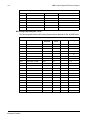
N2 Analog Input Objects - Bypass
The following table lists the N2 Analog Input objects defined for the ABB E-Clipse
bypass.
N2 Analog Inputs:
Number
Object
Bypass
Parameter
Scale
Factor
Units
AI1
CURRENT
0101
10
AI2
LAST FAULT
0401
1
fault code
AI3
ALARM WORD 1
0308
1
Alarm mask
(see bypass
manual
description of
parameter
0308)
Embedded Fieldbus
A
Range
0…9999
ABB E-Clipse Bypass EFB User’s Manual
39
N2 Analog Inputs:
Number
Bypass
Parameter
Object
AI4
ALARM WORD 2
AI5
HAND OFF AUTO
0309
Scale
Factor
Units
Range
1
Alarm mask
(see bypass
manual
description of
parameter
0309)
0=Off, 1=Hand,
2=Auto
N2 Analog Output Objects - Bypass
The following table lists the N2 Analog Ouput objects defined for the ABB E-Clipse
bypass.
N2 Analog Outputs:
Number
AO1
Object
BYP RUNDLY
Bypass
Parameter
1614
Scale
Factor
1
Units
Range
s
0...300
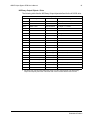
N2 Binary Input Objects - Bypass
The following table lists the N2 Binary Input objects defined for the ABB E-Clipse
bypass.
N2 Binary Inputs:
Number
Object
Bypass Parameter
Range
BI1
SYSTEM READY
Status Word
1 = Ready
BI2
SYSTEM ENABLED
Status Word
1 = Enabled
BI3
SYSTEM STARTED
Status Word
1 = System Started
BI4
SYSTEM RUNNING
Status Word
1 = System Running
BI5
N2 LOCAL MODE
Status Word
1 = N2 Local
BI6
FAULT
Status Word
1 = Bypass Fault
BI7
ALARM
Status Word
1 = Bypass Alarm
BI8
N2 CONTROL SRC
Status Word
1 = Yes
BI9
OVERRIDE
Status Word
1 = Override
BI10
INPUT 1 STATUS
0103 (bit mask 1)
1 = On
BI11
INPUT 2 STATUS
0103 (bit mask 2)
1 = On
BI12
INPUT 3 STATUS
0103 (bit mask 4)
1 = On
BI13
INPUT 4 STATUS
0103 (bit mask 8)
1 = On
BI14
INPUT 5 STATUS
0103 (bit mask 10h)
1 = On
BI15
INPUT 6 STATUS
0103 (bit mask 20h)
1 = On
BI16
RELAY 1 STATUS
0104 (bit mas 1)
1 = On
BI17
RELAY 2 STATUS
0104 (bit mas 2)
1 = On
BI18
RELAY 3 STATUS
0104 (bit mas 4)
1 = On
Embedded Fieldbus
40
ABB E-Clipse Bypass EFB User’s Manual
N2 Binary Inputs:
Number
Object
Bypass Parameter
Range
BI19
RELAY 4 STATUS
0104 (bit mas 8)
1 = On
BI20
RELAY 5 STATUS
0104 (bit mas 10h)
1 = On
BI21
BYPASS MODE
Status Word
0 = Drive mode; 1 = Bypass mode
BI22
SYS UNDERLOAD
Status Word
1 = System Underload
BI23
SYS FAULT
Status Word
1 = System Fault
BI24
BYPASS RUNNING
Status Word
1 = Bypass Running
N2 Binary Output Objects - Bypass
The following table lists the N2 Binary Output objects defined for the ABB E-Clipse
bypass.
N2 Binary Outputs:
Number
Object
Bypass Parameter
Range
BO1
SYSTEM START
Command Word
1 = Started
BO2
SYSTEM DISABLE
Command Word
1 = Disable
BO3
SYSTEM RESET
Command Word
Change 0->1 = Fault Reset
BO4
OVERRIDE
Command Word
1 = Override
BO5
COMMAND RO 1
0107 (bit mask 1)
1 = On
BO6
COMMAND RO 2
0107 (bit mask 2)
1 = On
BO7
COMMAND RO 3
0107 (bit mask 4)
1 = On
BO8
COMMAND RO 4
0107 (bit mask 8)
1 = On
BO9
COMMAND RO 5
0107 (bit mask 10h) 1 = On
BO10
START DISABLE 1
Command Word
1 = Disable
BO11
START DISABLE 2
Command Word
1 = Disable
BO12
START DISABLE 3
Command Word
1 = Disable
BO13
START DISABLE 4
Command Word
1 = Disable
Embedded Fieldbus
ABB E-Clipse Bypass EFB User’s Manual
41
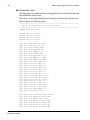
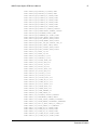
DDL File for NCU - Bypass
The listing below is the Data Definition Language (DDL) file for ABB E-Clipse bypass
used with the Network Control Units.
This listing is useful when defining bypass I/O objects to the Network Controller
Units.
Below is the ABB E-Clipse bypass file listing.
*******************************************************************
* ABB bypass, ACH 550 Variable Frequency Bypass
*******************************************************************
CSMODEL "E-Clipse_Bypass","VND"
AITITLE
BITITLE
AOTITLE
BOTITLE
"Analog
"Binary
"Analog
"Binary
Inputs"
Inputs"
Outputs"
Outputs"
CSAI
CSAI
CSAI
CSAI
CSAI
"AI1",N,N,"CURRENT","A"
"AI2",N,N,"LAST FLT","Code"
"AI3",N,N,"ALARM WD 1","Code"
"AI4",N,N,"ALARM WD 2","Code"
"AI5",N,N,"HAND OF AUTO","Code"
CSBI
CSBI
CSBI
CSBI
CSBI
CSBI
CSBI
CSBI
CSBI
CSBI
CSBI
CSBI
CSBI
CSBI
CSBI
CSBI
CSBI
CSBI
CSBI
CSBI
CSBI
CSBI
CSBI
CSBI
"BI1",N,N,"SYST RDY","NO","YES"
"BI2",N,N,"SYST ENBL","DISABLE","ENABLED"
"BI3",N,N,"SYST STRT","NO","YES"
"BI4",N,N,"SYST RUN","NO","YES"
"BI5",N,N,"N2 LCL MD","NO","YES"
"BI6",N,N,"FAULT","NO","YES"
"BI7",N,N,"ALARM","NO","YES"
"BI8",N,N,"N2 CTRL SRC","NO","YES"
"BI9",N,N,"OVERRIDE","NO","YES"
"BI10",N,N,"INPUT 1","OFF","ON"
"BI11",N,N,"INPUT 2","OFF","ON"
"BI12",N,N,"INPUT 3","OFF","ON"
"BI13",N,N,"INPUT 4","OFF","ON"
"BI14",N,N,"INPUT 5","OFF","ON"
"BI15",N,N,"INPUT 6","OFF","ON"
"BI16",N,N,"RELAY 1","OFF","ON"
"BI17",N,N,"RELAY 2","OFF","ON"
"BI18",N,N,"RELAY 3","OFF","ON"
"BI19",N,N,"RELAY 4","OFF","ON"
"BI20",N,N,"RELAY 5","OFF","ON"
"BI21",N,N,"BP MODE","OFF","ON"
"BI22",N,N,"SYS ULOAD","NO","YES"
"BI23",N,N,"SYS FLT","YES","NO"
"BI24",N,N,"BP RUN","NO","YES"
Embedded Fieldbus
42
ABB E-Clipse Bypass EFB User’s Manual
CSAO "AO1",Y,Y,"BP RUNDLY","S"
CSBO
CSBO
CSBO
CSBO
CSBO
"BO1",Y,Y," SYS STRT","STOP","START"
"BO2",Y,Y,"SYS DSABLE","ENABLE","DISABLE"
"BO3",Y,Y,"SYS RSET","OFF","RESET"
"BO4",Y,Y,"OVERRIDE","OFF","OVERRIDE"
"BO5",Y,Y,"CMD RO 1","OFF","ON"
CSBO "BO6",Y,Y,"CMD RO 2","OFF","ON"
CSBO "BO7",Y,Y,"CMD RO 3","OFF","ON"
CSBO "BO8",Y,Y,"CMD RO 4","OFF","ON"
CSBO "BO9",Y,Y,"CMD RO 5","OFF","ON"
CSBO "BO10",Y,Y,"STRT DSA 1","OFF","ON"
CSBO "BO11",Y,Y,"STRT DSA 2","OFF","ON"
CSBO "BO11",Y,Y,"STRT DSA 3","OFF","ON"
CSBO "BO11",Y,Y,"STRT DSA 4","OFF","ON"
Embedded Fieldbus
ABB E-Clipse Bypass EFB User’s Manual
43
FLN Protocol Technical Data - System
System Overview
The FLN fieldbus connection to the E-Clipse Bypass system is based on an industry
standard RS-485 physical interface. The FLN (Floor Level Network) Fieldbus
protocol is a serial communication protocol, used by the Siemens APOGEE®
system. The system interface is specified in Siemens application 2734.
Supported Features
The system supports all required FLN features.
When bypass parameter 1625 COMM CTL = (0) DRIVE ONLY, the drive’s FLN
points are all supported using the drive’s device address. The bypass’s FLN points
related to the control word are no longer valid.
Bypass FLN Points Not Valid
Point #
Name
24
RUN.STOP CMD
26
OVERRIDE CMD
35
RUN ENA CMD
50
START ENA 1
51
START ENA 2
52
START ENA 3
53
START ENA 4
94
RESET FAULT
When bypass parameter 1625 COMM CTL = (1) SYSTEM, the drive’s FLN following
objects related to control are no longer available when using the drive’s device
address.
Drive FLN Objects Not Valid
Point #
Name
24
RUN.STOP CMD
35
ENA DIS CMD
Embedded Fieldbus
44
ABB E-Clipse Bypass EFB User’s Manual
Drive Overview
Reports
The ACH550 provides seven pre-defined reports. Using a report request generated
from the FLN fieldbus controller, select one of the following sets of points. By
providing views of selected points, these reports are often easier to work with than
views of the full point database.
ABB ACH550
FLN ABB ACH550 Report
Point
Subpoint Name
#
Type
01
LAO
CTLR ADDRESS
02
LAO
APPLICATION
20
LAO
OVRD TIME
29
LDO
DAY.NIGHT
Data
Each host FLN application (e.g. CIS or Insight) controls
both the particular data reported for each point, and the
report format.
Startup
FLN Startup Report
Point
#
Type
Subpoint Name
21
LDI
FWD.REV
22
LDO
CMD FWD.REV
23
LDI
STOP.RUN
24
LDO
CMD STP.STRT
25
LDI
EXT1.2 ACT
26
LDO
EXT1.2 CMD
34
LDI
ENA.DIS ACT
35
LDO
ENA.DIS CMD
36
LDI
FLN LOC ACT
60
LAO
INPUT REF1
61
LAO
INPUT REF2
68
LDO
FLN LOC CTL
69
LDO
FLN LOC REF
94
LDO
RESET FAULT
Embedded Fieldbus
Data
Each host FLN application (e.g. CIS or Insight) controls
both the particular data reported for each point, and the
report format.
ABB E-Clipse Bypass EFB User’s Manual
45
Overview
FLN Overview Report
Point
#
Type
Subpoint Name
03
LAI
FREQ OUTPUT
04
LAI
PCT OUTPUT
05
LAI
SPEED
06
LAI
CURRENT
07
LAI
TORQUE
08
LAI
POWER
09
LAI
DRIVE TEMP
10
LAI
DRIVE KWH
11
LAI
DRIVE MWH
12
LAI
RUN TIME
13
LAI
DC BUS VOLT
14
LAI
OUTPUT VOLT
17
LAI
MOTOR TEMP
18
LAI
MREV COUNTER
21
LDI
FWD.REV
23
LDI
STOP.RUN
25
LDI
EXT1.2 ACT
27
LDI
DRIVE READY
28
LDI
AT SETPOINT
33
LDI
HANDAUTO ACT
34
LDI
ENA.DIS ACT
36
LDI
FLN LOC ACT
Data
Each host FLN application (e.g. CIS or Insight) controls
both the particular data reported for each point, and the
report format.
Drive I/O
FLN Drive I/O Report
Point
Subpoint Name
#
Type
40
LDO
RO 1 COMMAND
41
LDO
RO 2 COMMAND
42
LDO
RO 3 COMMAND
43
LDO
RO 4 COMMAND
44
LDO
RO 5 COMMAND
45
LDO
RO 6 COMMAND
46
LAO
AO 1 COMMAND
47
LAO
AO 2 COMMAND
70
LDI
DI 1 ACTUAL
Data
Each host FLN application (e.g. CIS or Insight) controls
both the particular data reported for each point, and the
report format.
Embedded Fieldbus
46
ABB E-Clipse Bypass EFB User’s Manual
FLN Drive I/O Report
Point
#
Type
Subpoint Name
71
LDI
DI 2 ACTUAL
72
LDI
DI 3 ACTUAL
73
LDI
DI 4 ACTUAL
74
LDI
DI 5 ACTUAL
75
LDI
DI 6 ACTUAL
76
LDI
RO 1 ACTUAL
77
LDI
RO 2 ACTUAL
78
LDI
RO 3 ACTUAL
79
LDI
RO 4 ACTUAL
80
LDI
RO 5 ACTUAL
81
LDI
RO 6 ACTUAL
85
LAI
AO 2 ACTUAL
Data
Drive Config
FLN Drive Config. Report
Point
Subpoint Name
#
Type
30
LAO
CURRENT LIM
31
LAO
ACCEL TIME 1
32
LAO
DECEL TIME 1
48
LDO
RST RUN TIME
49
LDO
RESET KWH
59
LDO
LOCK PANEL
66
LDO
SPD OUT MIN
67
LDO
SPD OUT MAX
95
LAO
MBOX PARAM
96
LAO
MBOX DATA
97
LDO
MBOX READ
98
LDO
MBOX WRITE
Data
Each host FLN application (e.g. CIS or Insight) controls
both the particular data reported for each point, and the
report format.
Process PID
FLN Process PID Report
Point
#
Type
Subpoint Name
15
LAI
PRC PID FBCK
16
LAI
PRC PID DEV
50
LAO
PRC PID GAIN
Embedded Fieldbus
Data
Each host FLN application (e.g. CIS or Insight) controls
both the particular data reported for each point, and the
report format.
ABB E-Clipse Bypass EFB User’s Manual
47
FLN Process PID Report
Point
Data
Subpoint Name
#
Type
51
LAO
PRC PID ITIM
52
LAO
PRC PID DTIM
53
LAO
PRC PID DFIL
54
LDO
PRC PID SEL
60
LAO
INPUT REF1
61
LAO
INPUT REF2
82
LAI
AI 1 ACTUAL
83
LAI
AI 2 ACTUAL
84
LAI
AO 1 ACTUAL
85
LAI
AO 2 ACTUAL
External PID
FLN External PID Report
Point
Subpoint Name
#
Type
55
LAO
EXT PID GAIN
56
LAO
EXT PID ITIM
57
LAO
EXT PID DTIM
58
LAO
EXT PID DFIL
62
LAO
EXT PID STPT
63
LAI
EXT PID FBCK
64
LAI
EXT PID DEV
82
LAI
AI 1 ACTUAL
83
LAI
AI 2 ACTUAL
84
LAI
AO 1 ACTUAL
85
LAI
AO 2 ACTUAL
Data
Each host FLN application (e.g. CIS or Insight) controls
both the particular data reported for each point, and the
report format.
Scaling Drive Feedback Values
Feedback values are provided with units of percent, where 0% and 100%
correspond to the range of the sensor being used to measure the control variable.
These points have default units in Hz. If other units are required:
• Unbundle these points with appropriate slopes and intercepts.
• The new intercept equals the lowest value of the desired range.
• Calculate the new slope as follows:
New Slope =
=
(Desired Range, i.e. high - low values) x (Slope of Existing Point)
Range of Existing Point
(60 Hz - 0 Hz) x (0.01)
100% - 0%
= 0.006
Embedded Fieldbus
48
ABB E-Clipse Bypass EFB User’s Manual
Example – You are controlling water temperature from a cooling tower using the
ACH550 to control a fan. The temperature sensor has a range of 30 to 250 degrees
Fahrenheit.
To unbundle the set point (INPUT REF 2), for commanding in degrees Fahrenheit,
where 0…60 Hz is equal to 30…250° F:
New Intercept = 30 (the temperature that corresponds to 0%)
New Slope =
=
(Desired Range) x (Slope of Existing Point)
Range of Existing Point
(250° F - 30° F) x (0.1)
100% - 0%
= 0.22
To unbundle the feedback (PRC PID FBCK) for monitoring in degrees Fahrenheit:
New Intercept = 30
New Slope =
=
(Desired Range) x (Slope of Existing Point)
Range of Existing Point
(250° F - 30° F) x (0.01)
100% - 0%
= 0.022
Loop Gains
PRC PID GAIN (Point 50) and PRC PID ITIM (Point 51) are PID parameters similar
to the P and I gains in the APOGEE TECs. Because the ABB PI loop and the
Siemens loop are structured differently, there is no a one-to-one correspondence
between the gains. The following formulas allow translation from ABB gains to
Siemens gains and vice versa:
• To convert from ABB PI gains to Siemens P and I gains:
P GAINSiemens = PI GAINABB x 0.0015
I GAINSiemens=
PI GAINABB
x 0.0015
PI GAINABB
• To convert from Siemens P and I gains to ABB PI gains:
P GAINABB = PI GAINSiemens x 667
I GAINABB =
Embedded Fieldbus
PI GAINSiemens
x 667
PI GAINSiemens
ABB E-Clipse Bypass EFB User’s Manual
49
Point Database
The following table lists the point database for FLN / ACH550 (Application 2734).
FLN Point Database
Point
Subpoint Name
Factory
Default
Engr.
Units
Slope
#
Type
01
LAO
CTLR ADDRESS 99
-
1
02
LAO
APPLICATION
2734
-
1
{03}
LAI
FREQ OUTPUT
0
Hz
0.1
{04}
LAI
PCT OUTPUT
0
PCT
{05}
LAI
SPEED
0
{06}
LAI
CURRENT
{07}
LAI
{08}
Intercept
On Text
Off Text
(SI Units)
0
-
-
-
-
0
-
-
0.1
0
-
-
RPM
1
0
-
-
0
A
0.1
-
-
TORQUE
0
PCT
0.1
-200
-
-
LAI
POWER
0
(0)
HP
(KW)
0.134
0.1
0
0
-
-
{09}
LAI
DRIVE TEMP
77
(25)
°F
(° C)
0.18
(0.1)
32
0
-
-
{10}
LAI
DRIVE KWH
0
KWH
1
-
-
{11}
LAI
DRIVE MWH
0
MWH
1
-
-
{12}
LAI
RUN TIME
0
HRS
1
-
-
{13}
LAI
DC BUS VOLT
0
V
1
-
-
{14}
LAI
OUTPUT VOLT
0
V
1
-
-
{15}
LAI
PRC PID FBCK
0
PCT
0.1
-
-
{16}
LAI
PRC PID DEV
0
PCT
0.1
-
-
{17}
LAI
MOTOR TEMP
77(25)
° F (° C)
1.8 (1)
32 0
-
-
{18}
LAI
MREV
COUNTER
0
MREV
1
0
-
-
20
LAO
OVRD TIME
1
hrs
1
0
-
-
{21}
LDI
FWD.REV
FWD
-
1
0
REV
FWD
{22}
LDO
CMD FWD.REV
FWD
-
1
0
REV
FWD
{23}
LDI
STOP.RUN
STOP
-
1
0
RUN
STOP
{24}
LDO
CMD STP.STRT
STOP
-
1
0
RUN
STOP
{25}
LDI
EXT1.2 ACT
EXT1
-
1
0
EXT2
EXT1
{26}
LDO
EXT1.2 CMD
EXT1
-
1
0
EXT2
EXT1
{27}
LDI
DRIVE READY
NOTRDY -
1
0
READY
NOTRDY
{28}
LDI
AT SETPOINT
NO
-
1
0
YES
NO
{29}
LDO
DAY.NIGHT
DAY
-
1
0
NIGHT
DAY
30
LAO
CURRENT LIM
0
A
0.1
0
-
-
31
LAO
ACCEL TIME 1
300
sec
0.1
0
-
-
32
LAO
DECEL TIME 1
300
sec
0.1
0
-
-
{33}
LDI
HANDAUTO
ACT
AUTO
-
1
0
HAND
AUTO
Embedded Fieldbus
50
ABB E-Clipse Bypass EFB User’s Manual
FLN Point Database
Point
#
Subpoint Name
Factory
Default
Engr.
Units
Type
Slope
Intercept
On Text
Off Text
(SI Units)
{34}
LDI
ENA.DIS ACT
DISABL
-
1
0
ENABLE
DISABL
{35}
LDO
ENA.DIS CMD
DISABL
-
1
0
ENABLE
DISABL
{36}
LDI
FLN LOC ACT
AUTO
-
1
0
FLN
AUTO
{37}
LDI
CTL SRC
NO
-
1
0
YES
NO
{38}
LDI
FLN REF1 SRC
NO
-
1
0
YES
NO
{39}
LDI
FLN REF2 SRC
NO
-
1
0
YES
NO
{40}
LDO
RO 1
COMMAND
OFF
-
1
0
ON
OFF
{41}
LDO
RO 2
COMMAND
OFF
-
1
0
ON
OFF
{42}
LDO
RO 3
COMMAND
OFF
-
1
0
ON
OFF
{43}
LDO
RO 4
COMMAND
OFF
-
1
0
ON
OFF
{44}
LDO
RO 5
COMMAND
OFF
-
1
0
ON
OFF
{45}
LDO
RO 6
COMMAND
OFF
-
1
0
ON
OFF
{46}
LAO
AO 1
COMMAND
PCT
PCT
0.1
0
-
-
{47}
LAO
AO 2
COMMAND
PCT
PCT
0.1
0
-
-
48
LDO
RST RUN TIME
NO
-
1
0
RESET
NO
49
LDO
RESET KWH
NO
-
1
0
RESET
NO
50
LAO
PRC PID GAIN
10
PCT
0.1
0
-
-
51
LAO
PRC PID ITIM
600
SEC
0.1
0
-
-
52
LAO
PRC PID DTIM
0
SEC
0.1
0
-
-
53
LAO
PRC PID DFIL
10
SEC
0.1
0
-
-
54
LDO
PRC PID SEL
SET1
-
1
0
SET2
SET1
55
LAO
EXT PID GAIN
10
PCT
0.1
0
-
-
56
LAO
EXT PID ITIM
600
SEC
0.1
0
-
-
57
LAO
EXT PID DTIM
0
SEC
0.1
0
-
-
58
LAO
EXT PID DFIL
10
SEC
0.1
0
-
-
59
LDO
LOCK PANEL
UNLOCK
-
1
0
LOCK
UNLOCK
{60}
LAO
INPUT REF1
0
PCT
0.1
0
-
-
{61}
LAO
INPUT REF2
0
PCT
0.1
0
-
-
{62}
LAO
EXT PID STPT
0
PCT
0.1
0
-
-
{63}
LAI
EXT PID FBCK
0
PCT
0.1
0
-
-
{64}
LAI
EXT PID DEV
0
PCT
0.1
0
-
-
Embedded Fieldbus
ABB E-Clipse Bypass EFB User’s Manual
51
FLN Point Database
Point
Factory
Default
Subpoint Name
Engr.
Units
Slope
Intercept
On Text
Off Text
#
Type
(SI Units)
66
LDO
SPD OUT MIN
0
PCT
0.1
0
-
-
67
LDO
SPD OUT MAX
1000
PCT
0.1
0
-
-
{68}
LDO
FLN LOC CTL
AUTO
-
1
0
FLN
AUTO
{69}
LDO
FLN LOC REF
AUTO
-
1
0
FLN
AUTO
{70}
LDI
DI 1 ACTUAL
OFF
-
1
0
ON
OFF
{71}
LDI
DI 2 ACTUAL
OFF
-
1
0
ON
OFF
{72}
LDI
DI 3 ACTUAL
OFF
-
1
0
ON
OFF
{73}
LDI
DI 4 ACTUAL
OFF
-
1
0
ON
OFF
{74}
LDI
DI 5 ACTUAL
OFF
-
1
0
ON
OFF
{75}
LDI
DI 6 ACTUAL
OFF
-
1
0
ON
OFF
{76}
LDI
RO 1 ACTUAL
OFF
-
1
0
ON
OFF
{77}
LDI
RO 2 ACTUAL
OFF
-
1
0
ON
OFF
{78}
LDI
RO 3 ACTUAL
OFF
-
1
0
ON
OFF
{79}
LDI
RO 4 ACTUAL
OFF
-
1
0
ON
OFF
{80}
LDI
RO 5 ACTUAL
OFF
-
1
0
ON
OFF
{81}
LDI
RO 6 ACTUAL
OFF
-
1
0
ON
OFF
{82}
LAI
AI 1 ACTUAL
0
PCT
0.1
0
-
-
{83}
LAI
AI 2 ACTUAL
0
PCT
0.1
0
-
-
{84}
LAI
AO 1 ACTUAL
0
MA
0.1
0
-
-
{85}
LAI
AO 2 ACTUAL
0
MA
0.1
0
-
-
{86}
LDI
OK.ALARM
OK
-
1
0
ALARM
OK
{87}
LDI
OK.MAINT
OK
-
1
0
MAINT
OK
{88}
LAI
ALARM WORD 1 -
-
1
0
-
-
{89}
LAI
ALARM WORD 2 -
-
1
0
-
-
{90}
LAI
LAST FAULT
-
-
1
0
-
-
{91}
LAI
PREV FAULT 1
-
-
1
0
-
-
{92}
LAI
PREV FAULT 2
-
-
1
0
-
-
{93}
LDI
OK.FAULT
OK
-
1
0
FAULT
OK
{94}
LDO
RESET FAULT
NO
-
1
0
RESET
NO
{95}
LAO
MBOX PARAM
-
-
1
0
-
-
{96}
LAO
MBOX DATA
-
-
1
0
-
-
{97}
LDO
MBOX READ
DONE
-
1
0
READ
DONE
{98}
LDO
MBOX WRITE
DONE
-
1
0
WRITE
DONE
{99}
LAO
ERROR STATUS -
-
1
0
-
-
a. Points not listed are not used in this application.
b. A single value in a column means that the value is the same in English units and in SI units.
c. Point numbers that appear in brackets { } may be unbundled at the field panel.
Embedded Fieldbus
52
ABB E-Clipse Bypass EFB User’s Manual
Detailed Point Descriptions
FLN Detailed Point Descriptions
Point
Description
Drive
Parameter
1
CTRL ADDRESS The FLN address of the drive. It can be set by FLN and by
the panel.
2
APPLICATION
The Application ID for FLN on the ACH550. This ID is
assigned by Siemens for each unique application. It
correlates directly to a particular point list approved at the
time of release. Therefore, this point list shall remain fixed
once approval is granted. Any changes to the point list shall
require a new Application ID and re-approval by Siemens.
The Application ID assigned to ACH550 is 2934.
3
FREQ OUTPUT
The output frequency applied to the motor, in Hertz.
0103
4
PCT OUTPUT
The ratio of output frequency or speed to the corresponding
maximum rating, depending on control mode.
• For scalar mode, it is the ratio of Output Frequency
(parameter 0103) to Maximum Frequency (parameter
2008).
• For speed mode, it is the ratio Speed (parameter 0102) to
Maximum Speed (2002).
None. This
ratio is
calculated
by the FLN
application.
5
SPEED
The calculated speed of the motor, in RPM.
0102
6
CURRENT
The measured output current.
0104
7
TORQUE
The calculated output torque of the motor as a percentage of
nominal torque.
0105
8
POWER
The measured output power in KW. The FLN point definition
also supports horsepower by selecting English units.
0106
DRIVE TEMP
The measured heatsink temperature, in ° C. The FLN point
definition also supports ° F by selecting English units.
0110
10
DRIVE KWH
The drive's cumulative power consumption in kilowatt-hours.
This value may be reset by commanding FLN point 49,
RESET KWH.
0115
11
DRIVE MWH
The drive's cumulative power consumption in megawatt
hours. This value cannot be reset.
0141
12
RUN TIME
The drive's cumulative run time in hours. This value may be
reset by commanding FLN point 48, RESET RUN TIME.
0114
13
DC BUS VOLT
The DC bus voltage level of the drive.
0107
14
OUTPUT VOLT
The AC output voltage applied to the motor.
0109
15
PRC PID FBCK
The Process PID feedback signal.
0130
16
PRC PID DEV
The deviation of the Process PID output signal from its
setpoint.
0132
17
MOTOR TEMP
The measured motor temperature as set up in Group 35.
0145
18
ROTATION CNT
The motor's cumulative revolution count, in megarevolutions.
0142
19
N/A
20
OVRD TIME
1 of the 5 mandatory FLN points required for compatibility
with Siemens control systems. It has no functionality in the
drive application.
None
Embedded Fieldbus
5302
ABB E-Clipse Bypass EFB User’s Manual
53
FLN Detailed Point Descriptions
Point
Drive
Parameter
Description
21
FWD.REV ACT
Indicates the rotational direction of the motor, regardless of
control source (1 = REV, 0 = FWD).
22
FWD.REV CMD
Commanded by FLN to change the rotational direction of the
drive.
• Parameter 1001 must be set to COMM for FLN to control
the direction of the motor by EXT1.
• Parameter 1002 must be set to COMM for FLN to control
the direction of the motor by EXT2.
23
RUN.STOP ACT
Indicates the drive's run status, regardless of control source
(1 = RUN, 0 = STOP).
24
RUN.STOP CMD Commanded by FLN to start the drive.
• Parameter 1001 must be set to COMM for FLN to control
the run state of the drive by EXT1.
• Parameter 1002 must be set to COMM for FLN to have
this control.
25
EXT1.2 ACT
Indicates whether External 1 or External 2 is the active
control source (1 = EXT2, 0 = EXT1).
26
EXT1.2 CMD
Commanded by FLN to select External 1 or External 2 as the
active control source (1 = EXT2, 0 = EXT1).
Parameter 1102 must be set to COMM for FLN to have this
control.
27
DRIVE READY
Indicates the drive is ready to accept a run command
(1 = READY, 0 = NOTRDY).
28
AT SETPOINT
Indicates the drive has reached its commanded setpoint
(1 = YES, 0 = NO)
29
DAY.NIGHT
1 of the 5 mandatory FLN points required for compatibility
with Siemens control systems. It has no functionality in the
drive application.
None
30
CURRENT LIM
Sets the output current limit of the drive.
2003
31
ACCEL TIME 1
Sets the acceleration time for Ramp 1.
2202
32
DECEL TIME 1
Sets the deceleration time for Ramp 1.
2203
33
HANDAUTO
ACT
Indicates whether the drive is in Hand or Auto control
(1 = HAND, 0 = AUTO).
34
ENA.DIS ACT
Indicates the status of the Run Enable command, regardless
of its source (1 = ENABLE, 0 = DISABL).
35
ENA.DIS CMD
Commanded by FLN to assert the Run Enable command
(1 = ENABLE, 0 = DISABL).
Parameter 1601 must be set to COMM for FLN to have this
control.
36
FLN LOC ACT
Indicates if the drive has been placed in “FLN LOCAL” mode
by commanding either point 68 (FLN LOC CTL) or point 69
(FLN LOC REF). Commanding either of these points to FLN
(1) “steals” control from its normal source and places in under
FLN control.
Note that the HAND mode of the panel has priority over FLN
local control.
Embedded Fieldbus
54
ABB E-Clipse Bypass EFB User’s Manual
FLN Detailed Point Descriptions
Point
Description
Drive
Parameter
37
FLN CTL SRC
Indicates if FLN is a source for control inputs
(1 = YES, 0 = NO).
Note that this status point is true if any of the following control
inputs are from FLN: Run/Stop, Ext1/2 Select or Run Enable.
38
FLN REF1 SRC
Indicates if FLN is the source for speed reference 1
(1 = YES, 0 = NO).
39
FLN REF2 SRC
Indicates if FLN is the source for speed reference 2
(1 = YES, 0 = NO).
40
RO1 COMMAND
Controls the output state of Relay 1.
Parameter 1401 must be set to COMM for FLN to have this
control (1 = ON, 0 = OFF).
0134, bit 0
41
RO2 COMMAND
Controls the output state of Relay 2.
Parameter 1402 must be set to COMM for FLN to have this
control (1 = ON, 0 = OFF).
0134, bit 1
42
RO3 COMMAND
Controls the output state of Relay 3.
Parameter 1403 must be set to COMM for FLN to have this
control (1 = ON, 0 = OFF).
0134, bit 2
43
RO4 COMMAND
Controls the output state of Relay 4. Access to relay 4 require
ACH550 option OREL.
Parameter 1410 must be set to COMM for FLN to have this
control (1 = ON, 0 = OFF).
0134, bit 3
44
RO5 COMMAND
Controls the output state of Relay 5. Access to relay 5 require
ACH550 option OREL.
Parameter 1411 must be set to COMM for FLN to have this
control (1 = ON, 0 = OFF).
0134, bit 4
45
RO6 COMMAND
Controls the output state of Relay 6. Access to relay 6 require
ACH550 option OREL.
Parameter 1412 must be set to COMM for FLN to have this
control (1 = ON, 0 = OFF).
0134, bit 5
46
AO1 COMMAND
Controls Analog Output 1.
Parameter 1501 must be set to this value for FLN to have this
control.
0135
(COMM
VALUE 1)
47
AO2 COMMAND
Controls Analog Output 2.
Parameter 1507 must be set to this value for FLN to have this
control.
0136
(COMM
VALUE 2)
48
RESET RUN
TIME
Commanded by FLN to reset the cumulative run timer (1 =
RESET, 0 = NO).
The control input is rising-edge sensitive, so, once the
command is issued, this point automatically returns to its
inactive state. This “momentary” operation avoids any need
for an explicit command to clear the point before a
subsequent reset can be issued.
49
RESET KWH
Commanded by FLN to reset the cumulative kilowatt-hour
counter (1 = RESET, 0 = NO).
The control input is rising-edge sensitive, so, once the
command is issued, this point automatically returns to its
inactive state. This “momentary” operation avoids any need
for an explicit command to clear the point before a
subsequent reset can be issued.
Embedded Fieldbus
ABB E-Clipse Bypass EFB User’s Manual
55
FLN Detailed Point Descriptions
Point
Drive
Parameter
Description
50
PRC PID GAIN
Sets the proportional gain of the active Process PID set, as
selected by Point 54, PRC PID SEL (1 = SET2, 0 = SET1).
4001 (SET1)
4101 (SET2)
51
PRC PID ITIM
Sets the integration time of the active Process PID set, as
selected by Point 54, PRC PID SEL (1 = SET2, 0 = SET1).
4002 (SET1)
4102 (SET2)
52
PRC PID DTIM
Sets the derivation time of the active Process PID set, as
selected by Point 54, PRC PID SEL (1 = SET2, 0 = SET1).
4001 (SET1)
4101 (SET2)
53
PRC PID DFIL
Sets the time constant for the error-derivative of the active
Process PID set, as selected by Point 54, PRC PID SEL
(1 = SET2, 0 = SET1).
4004 (SET1)
4104 (SET2)
54
PRC PID SEL
Selects the active Process PID set (1 = SET2, 0 = SET1).
4027
55
EXT PID GAIN
Sets the proportional gain of the External PID controller.
4201
56
EXT PID ITIM
Sets the integration time of the External PID controller.
4202
57
EXT PID DTIM
Sets the derivation time of the External PID controller.
4203
58
EXT PID DFIL
Sets the time constant for the error-derivative of the External
PID controller.
4204
59
LOCK PANEL
Command by FLN to lock the panel and prevent parameter
changes (1 = LOCK, 0 = UNLOCK).
1602
60
INPUT REF 1
Sets Input Reference 1.
Parameter 1102 must be set to COMM for FLN to control this
value.
61
INPUT REF 2
Sets Input Reference 2.
Parameter 1106 must be set to COMM for FLN to control this
value.
62
EXT PID STPT
The setpoint for the External PID controller.
The function of this point requires parameter 4210, PID
Setpoint Select, to be set to 19 (Internal).
4211
63
EXT PID FBCK
The External PID feedback signal.
0131
64
EXT PID DEV
The deviation of the External PID output signal from its
setpoint.
0133
65
N/A
66
SPD OUT MIN
Sets the minimum output speed of the drive as a percentage
of the motor nominal rating.
2007
(SCALAR)
2001
(SPEED)
67
SPD OUT MAX
Sets the maximum output speed of the drive as a percentage
of the motor nominal rating.
2008
(SCALAR)
2002
(SPEED)
68
FLN LOC CTL
Commanded by FLN to temporarily “steal” start/stop control
of the drive from its normal source and place it under FLN
control. This functionality is analogous to placing the drive in
HAND mode at the panel, with the control being taken by
FLN instead. HAND mode at the panel has priority over this
point. Thus, this point is only effective in temporarily taking
control from the digital inputs or some other internal control
functionality.
Embedded Fieldbus
56
ABB E-Clipse Bypass EFB User’s Manual
FLN Detailed Point Descriptions
Point
Description
Drive
Parameter
69
FLN LOC REF
Commanded by FLN to temporarily “steal” input reference
control of the drive from its normal source and place it under
FLN control. This functionality is analogous to placing the
drive in HAND mode at the panel, with the reference control
being taken by FLN instead. HAND mode at the panel has
priority over this point. Thus, this point is only effective in
temporarily taking control from the analog inputs or some
other internal control functionality.
70
DI 1 ACTUAL
Indicates the status of Digital Input 1 (1 = ON, 0 = OFF).
0118, bit 2
71
DI 2 ACTUAL
Indicates the status of Digital Input 2 (1 = ON, 0 = OFF).
0118, bit 1
72
DI 3 ACTUAL
Indicates the status of Digital Input 3 (1 = ON, 0 = OFF).
0118, bit 0
73
DI 4 ACTUAL
Indicates the status of Digital Input 4 (1 = ON, 0 = OFF).
0119, bit 2
74
DI 5 ACTUAL
Indicates the status of Digital Input 5 (1 = ON, 0 = OFF).
0119, bit 1
75
DI 6 ACTUAL
Indicates the status of Digital Input 6 (1 = ON, 0 = OFF).
0119, bit 0
76
RO 1 ACTUAL
Indicates the status of Relay Output 1 (1 = ON, 0 = OFF).
0122, bit 2
77
RO 2 ACTUAL
Indicates the status of Relay Output 2 (1 = ON, 0 = OFF).
0122, bit 1
78
RO 3 ACTUAL
Indicates the status of Relay Output 3 (1 = ON, 0 = OFF).
0122, bit 0
79
RO 4 ACTUAL
Indicates the status of Relay Output 4 (1 = ON, 0 = OFF).
0123, bit 2
80
RO 5 ACTUAL
Indicates the status of Relay Output 5 (1 = ON, 0 = OFF).
0123, bit 1
81
RO 6 ACTUAL
Indicates the status of Relay Output 6 (1 = ON, 0 = OFF).
0123, bit 0
82
AI 1 ACTUAL
Indicates the input level of Analog Input 1.
0120
83
AI 2 ACTUAL
Indicates the input level of Analog Input 2.
0121
84
AO 1 ACTUAL
Indicates the output level of Analog Output 1.
0124
85
AO 2 ACTUAL
Indicates the output level of Analog Output 2.
0125
86
OK.ALARM
Indicates the current alarm state of the drive
(1 = ALARM, 0 = OK).
87
OK.MAINT
Indicates the current maintenance state of the drive
(1 = MAINT, 0 = OK).
Maintenance triggers are configured in drive parameter
Group 29.
88
ALARM WORD1
This point is a bit-field indicating active alarms in the drive.
0308
89
ALARM WORD2
This point is a bit-field indicating active alarms in the drive.
0309
90
LAST FAULT
This point is first in the drive's fault log and indicates the most
recent fault declared.
0401
91
PREV FAULT 1
This point is second in the drive's fault log and indicates the
previous fault declared.
0412
92
PREV FAULT 2
This point is last in the drive's fault log and indicates the
oldest fault in the log.
0413
93
OK.FAULT
Indicates the current fault state of the drive
(1 = FAULT, 0 = OK).
Embedded Fieldbus
ABB E-Clipse Bypass EFB User’s Manual
57
FLN Detailed Point Descriptions
Point
Drive
Parameter
Description
94
RESET FAULT
Command by FLN to reset a faulted drive
(1 = RESET, 0 = NO).
Parameter 1604 must be set to COMM for FLN to control this
state.
The control input is rising-edge sensitive, so, once the
command is issued, this point automatically returns to its
inactive state. This “momentary” operation avoids any need
for an explicit command to clear the point before a
subsequent reset can be issued.
95
MBOX PARAM
Sets the parameter to be used by the mailbox function.
96
MBOX DATA
Sets or indicates the data value of the mailbox function.
97
MBOX READ
Command by FLN to read the parameter value specified by
Point 95, MBOX PARAM. The parameter value is returned in
Point 96, MBOX DATA.
The control input is rising-edge sensitive, so, once the
command is issued, this point automatically returns to its
inactive state. This “momentary” operation avoids any need
for an explicit command to clear the point before a
subsequent reset can be issued.
98
MBOX WRITE
Command by FLN to write the data value specified by Point
96, MBOX DATA, to the parameter value specified by Point
95, MBOX PARAM.
The control input is rising-edge sensitive, so, once the
command is issued, this point automatically returns to its
inactive state. This “momentary” operation avoids any need
for an explicit command to clear the point before a
subsequent reset can be issued.
99
ERROR STATUS 1 of the 5 mandatory FLN points required for compatibility
with Siemens control systems. It has no functionality in the
drive application.
None
Bypass Overview
The FLN fieldbus connection to the ABB E-Clipse bypass is based on an industry
standard EIA 485 physical interface. The FLN (Floor Level Network) Fieldbus
protocol is a serial communication protocol, used by the Siemens APOGEE®
system. The ABB E-Clipse bypass interface is specified in Siemens application
2734.
Supported Features
The ABB E-Clipse bypass supports all required FLN features.
Reports
The ABB E-Clipse bypass provides seven pre-defined reports. Using a report
request generated from the FLN fieldbus controller, select one of the following sets
of points. By providing views of selected points, these reports are often easier to
work with than views of the full point database.
Embedded Fieldbus
58
ABB E-Clipse Bypass EFB User’s Manual
ABB E-Clipse Bypass
FLN E-Clipse bypass Report
Point
Subpoint Name
#
Type
01
LAO
CTLR ADDRESS
02
LAO
APPLICATION
20
LAO
OVRD TIME
29
LDO
DAY.NIGHT
Data
Each host FLN application (e.g. CIS or Insight) controls
both the particular data reported for each point, and the
report format.
Bypass Startup
FLN Report #1 (STARTUP)
Point
#
Subpoint Name
Type
23
LDI
MTR RUNNING
24
LDO
RUN.STOP CMD
27
LDI
SYSTEM READY
28
LDI
SYS STARTED
32
LDI
DRIVE.BYPASS
33
LDI
BYP RUNNING
34
LDI
RUN ENA ACT
35
LDO
RUN ENA CMD
50
LDO
START ENA 1
51
LDO
START ENA 2
52
LDO
START ENA 3
53
LDO
START ENA 4
94
LDO
RESET FAULT
Bypass Overview
FLN Overview Report
Point
#
Type
Subpoint Name
06
LAI
CURRENT
86
LDI
BYPASS ALARM
90
LAI
LAST FAULT
93
LDI
OK FAULT BYP
Embedded Fieldbus
Data
Each host FLN application (e.g. CIS or Insight) controls
both the particular data reported for each point, and the
report format.
ABB E-Clipse Bypass EFB User’s Manual
59
Bypass I/O
FLN Bypass I/O Report
Point
Subpoint Name
#
Type
40
LDO
RO 1 COMMAND
41
LDO
RO 2 COMMAND
42
LDO
RO 3 COMMAND
43
LDO
RO 4 COMMAND
44
LDO
RO 5 COMMAND
70
LDI
DI 1 ACTUAL
71
LDI
DI 2 ACTUAL
72
LDI
DI 3 ACTUAL
73
LDI
DI 4 ACTUAL
74
LDI
DI 5 ACTUAL
75
LDI
DI 6 ACTUAL
76
LDI
RO 1 ACTUAL
77
LDI
RO 2 ACTUAL
78
LDI
RO 3 ACTUAL
79
LDI
RO 4 ACTUAL
80
LDI
RO 5 ACTUAL
Data
Each host FLN application (e.g. CIS or Insight) controls
both the particular data reported for each point, and the
report format.
Point Database - Bypass
The following table lists the point database for FLN / ABB E-Clipse bypass (Application 2737).
FLN Point Database
Point
Factory
Default
Engr.
Units
Slope
Intercept
On Text
Off Text
0
-
-
1
0
-
-
A
0.1
0
-
-
NO
-
1
0
[YES]
[NO]
OVRD TIME
1
HRS
1
0
-
-
LDI
MTR RUNNING
STOP
-
1
0
[RUN]
[STOP]
{24}
LDO
RUN.STOP CMD
STOP
-
1
0
[RUN]
[STOP]
{25}
LDI
OVERRIDE ACT
OFF
-
1
0
[ON]
[OFF]
{26}
LDO
OVERRIDE CMD
OFF
1
0
[ON]
[OFF]
{27}
LDI
SYSTEM READY
NOT
READY
-
1
0
[READY]
[NOT
READY]
{28}
LDI
SYS STARTED
NO
-
1
0
[YES]
[NO]
{29}
LDO
DAY.NIGHT
DAY
-
1
0
[NIGHT]
[DAY]
30
LAO
BYP RUN DLY
0
SEC
1
0
-
-
Subpoint Name
#
Type
(SI Units)
01
LAO
CTRL ADDRESS
2
-
1
02
LAO
APPLICATION
2737
-
{06}
LAI
CURRENT
0
{07}
LDI
SYS UNDRLOAD
20
LAO
{23}
Embedded Fieldbus
60
ABB E-Clipse Bypass EFB User’s Manual
FLN Point Database
Point
Subpoint Name
Factory
Default
Engr.
Units
Slope
Intercept
On Text
Off Text
#
Type
(SI Units)
{31}
LAI
BYPASS MODE
0
-
1
0
-
-
{32}
LDI
DRIVE.BYPASS
DRIVE
-
1
0
[BYPASS]
[DRIVE]
{33}
LDI
BYP RUNNING
NO
-
1
0
[YES]
[NO]
{34}
LDI
RUN ENA ACT
DISABL
-
1
0
[ENABLE]
[DISABL]
{35}
LDO
RUN ENA CMD
DISABL
-
1
0
[ENABLE]
[DISABL]
{36}
LDI
FLN LOC ACT
AUTO
-
1
0
[FLN]
[AUTO]
{37}
LDI
FLN CTL SRC
NO
-
1
0
[YES]
[NO]
{40}
LDO
RO 1 COMMAND
OFF
-
1
0
[ON]
[OFF]
{41}
LDO
RO 2 COMMAND
OFF
-
1
0
[ON]
[OFF]
{42}
LDO
RO 3 COMMAND
OFF
-
1
0
[ON]
[OFF]
{43}
LDO
RO 4 COMMAND
OFF
-
1
0
[ON]
[OFF]
{44}
LDO
RO 5 COMMAND
OFF
-
1
0
[ON]
[OFF]
{50}
LDO
START ENA 1
DISABL
-
1
0
[ENABLE]
[DISABL]
{51}
LDO
START ENA 2
DISABL
-
1
0
[ENABLE]
[DISABL]
{52}
LDO
START ENA 3
DISABL
-
1
0
[ENABLE]
[DISABL]
{53}
LDO
START ENA 4
DISABL
-
1
0
[ENABLE]
[DISABL]
{70}
LDI
DI 1 ACTUAL
OFF
-
1
0
[ON]
[OFF]
{71}
LDI
DI 2 ACTUAL
OFF
-
1
0
[ON]
[OFF]
{72}
LDI
DI 3 ACTUAL
OFF
-
1
0
[ON]
[OFF]
{73}
LDI
DI 4 ACTUAL
OFF
-
1
0
[ON]
[OFF]
{74}
LDI
DI 5 ACTUAL
OFF
-
1
0
[ON]
[OFF]
{75}
LDI
DI 6 ACTUAL
OFF
-
1
0
[ON]
[OFF]
{76}
LDI
RO 1 ACTUAL
OFF
-
1
0
[ON]
[OFF]
{77}
LDI
RO 2 ACTUAL
OFF
-
1
0
[ON]
[OFF]
{78}
LDI
RO 3 ACTUAL
OFF
-
1
0
[ON]
[OFF]
{79}
LDI
RO 4 ACTUAL
OFF
-
1
0
[ON]
[OFF]
{80}
LDI
RO 5 ACTUAL
OFF
-
1
0
[ON]
[OFF]
{86}
LDI
BYPASS ALARM
OK
-
1
0
[ALARM]
[OK]
{88}
LAI
ALARM WORD 1
0
-
1
0
-
-
{89}
LAI
ALARM WORD 2
0
-
1
0
-
-
{90}
LAI
LAST FAULT
-
-
1
0
-
-
{93}
LDI
OK.FAULTBYP
OK
-
1
0
[FAULT]
[OK]
{94}
LDO
RESET FAULT
NO
-
1
0
[RESET]
[NO]
{99}
LAO
ERROR STATUS
-
-
1
0
-
-
a.Points not listed are not used in this application.
b. A single value in a column means that the value is the same in English units and in SI units.
c. Point numbers that appear in brackets { } may be unbundled at the field panel.
Embedded Fieldbus
ABB E-Clipse Bypass EFB User’s Manual
61
Detailed Point Descriptions
FLN Detailed Point Descriptions
Point
Bypass
Parameter
Description
1
CTRL ADDRESS
The FLN address of the bypass. It can be set by FLN and by
the panel.
2
APPLICATION
This is the Application ID for FLN on the E-Clipse Bypass.
This ID is assigned by Siemens for each unique application.
It correlates directly to a particular point list approved at the
time of release. Therefore, this point list shall remain fixed
once approval is granted. Any changes to the point list shall
require a new Application ID and re-approval by Siemens.
The Application ID assigned to the E-Clipse bypass is 2737.
{6}
CURRENT
Measured output current.
{7}
SYS UNDRLOAD This point indicates if the system is in an underload condition.
Detection of this condition is done with bypass parameters
3001-3003.
20
OVRD TIME
This is 1 of 5 mandatory FLN points required for compatibility
with Siemens control systems. It has no functionality in the
bypass application.
{23}
MTR RUNNING
This point indicates the system’s run status, regardless of
control source (1 = RUN, 0 = STOP).
{24}
RUN.STOP CMD
This point is commanded by FLN to start the system.
Bypass parameter 1601 must be set to COMM for FLN to
control the run state of the system.
{25}
OVERRIDE ACT
This point indicates if the bypass is in override 1 or override
2.
{26}
OVERRID CMD
This point is commanded by FLN to select bypass override 2.
Override 2 is configured by parameters in bypass group 17.
{27}
SYSTEM READY This point indicates the system is ready to accept a run
command (1 = READY, 0 = NOTRDY).
{28}
SYS STARTED
This point the system has received a run command and is
started. It may or may not be running based on the RUN
ENABLE status.
{29}
DAY.NIGHT
This is 1 of 5 mandatory FLN points required for compatibility
with Siemens control systems. It has no functionality in the
bypass application.
30
BYP RUN DLY
0101
This allows FLN to delay running of the system after a run
command has been issued.
{31}
BYPASS MODE
This point indicates the Hand/Off/Auto status of the bypass.
0=OFF; 1=HAND; 2=AUTO.
{32}
DRIVE.BYPASS
This point indicates if the system is selected to operate the
motor from the drive or from the bypass.
{33}
BYP RUNNING
This point indicates the bypass’s run status. It differs from the
system running status in that it only applies to the bypass’s
status not the logical OR of the drive and bypass status.
{34}
RUN ENA ACT
5002
1614
This point indicates the status of the system Run Enable
command, regardless of its source (1 = ENABLE, 0 =
DISABL).
Embedded Fieldbus
62
ABB E-Clipse Bypass EFB User’s Manual
FLN Detailed Point Descriptions
Point
Description
Bypass
Parameter
{35}
RUN ENA CMD
This point is commanded by FLN to assert the system Run
Enable command (1 = ENABLE, 0 = DISABL). Bypass
parameter 1602 must be set to COMM for FLN to have this
control.
{36}
FLN LOC ACT
This point indicates if the bypass has been placed in “FLN
LOCAL” mode by commanding ????. Commanding this
point to FLN (1) “steals” control from its normal source and
places in under FLN control. Note that the HAND mode of
the panel has priority over FLN local control.
{37}
FLN CTL SRC
This point indicates if FLN is a source for control inputs (1 =
YES, 0 = NO). Note that this status point is true if any of the
following control inputs are from FLN: Run/Stop, Run
Enable, Start Enable 1, Start Enable 2, Start Enable 3 or Start
Enable 4.
{40}
RO 1 COMMAND This point controls the output state of bypass Relay 1.
Bypass parameter 1401 must be set to COMM for FLN to
have this control (1 = ON, 0 = OFF).
0107, bit 0
{41}
RO 2 COMMAND This point controls the output state of bypass Relay 2.
Bypass parameter 1401 must be set to COMM for FLN to
have this control (1 = ON, 0 = OFF).
0107, bit 1
{42}
RO 3 COMMAND This point controls the output state of bypass Relay 3.
Bypass parameter 1401 must be set to COMM for FLN to
have this control (1 = ON, 0 = OFF).
0107, bit 2
{43}
RO 4 COMMAND This point controls the output state of bypass Relay 4.
Bypass parameter 1401 must be set to COMM for FLN to
have this control (1 = ON, 0 = OFF).
0107, bit 3
{44}
RO 5 COMMAND This point controls the output state of bypass Relay 5.
Bypass parameter 1401 must be set to COMM for FLN to
have this control (1 = ON, 0 = OFF).
0107, bit 4
{50}
START ENA 1
This point is commanded by FLN to assert the system Start
Enable 1 command (1 = ENABLE, 0 = DISABL). Bypass
parameter 1603 must be set to COMM for FLN to have this
control.
{51}
START ENA 2
This point is commanded by FLN to assert the system Start
Enable 1 command (1 = ENABLE, 0 = DISABL). Bypass
parameter 1603 must be set to COMM for FLN to have this
control.
{52}
START ENA 3
This point is commanded by FLN to assert the system Start
Enable 1 command (1 = ENABLE, 0 = DISABL). Bypass
parameter 1603 must be set to COMM for FLN to have this
control.
{53}
START ENA 4
This point is commanded by FLN to assert the system Start
Enable 1 command (1 = ENABLE, 0 = DISABL). Bypass
parameter 1603 must be set to COMM for FLN to have this
control.
{70}
DI 1 ACTUAL
This point indicates the status of bypass Digital Input 1 (1 =
ON, 0 = OFF).
0103, bit 5
{71}
DI 2 ACTUAL
This point indicates the status of bypass Digital Input 2 (1 =
ON, 0 = OFF).
0103, bit 4
{72}
DI 3 ACTUAL
This point indicates the status of bypass Digital Input 3 (1 =
ON, 0 = OFF).
0103, bit 3
Embedded Fieldbus
ABB E-Clipse Bypass EFB User’s Manual
63
FLN Detailed Point Descriptions
Point
Bypass
Parameter
Description
{73}
DI 4 ACTUAL
This point indicates the status of bypass Digital Input 4 (1 =
ON, 0 = OFF).
0103, bit 2
{74}
DI 5 ACTUAL
This point indicates the status of bypass Digital Input 5 (1 =
ON, 0 = OFF).
0103, bit 1
{75}
DI 6 ACTUAL
This point indicates the status of bypass Digital Input 6 (1 =
ON, 0 = OFF).
0103, bit 0
{76}
RO 1 ACTUAL
This point indicates the status of bypass Relay Output 1 (1 =
ON, 0 = OFF).
0104, bit 4
{77}
RO 2 ACTUAL
This point indicates the status of bypass Relay Output 2 (1 =
ON, 0 = OFF).
0104, bit 3
{78}
RO 3 ACTUAL
This point indicates the status of bypass Relay Output 3 (1 =
ON, 0 = OFF).
0104, bit 2
{79}
RO 4 ACTUAL
This point indicates the status of bypass Relay Output 4 (1 =
ON, 0 = OFF).
0104, bit 1
{80}
RO 5 ACTUAL
This point indicates the status of bypass Relay Output 5 (1 =
ON, 0 = OFF).
0104, bit 0
86
BYPASS ALARM
This point indicates the current alarm state of the bypass (1 =
ALARM, 0 = OK).
88
ALARM WORD1
This point is a bit-field indicating active alarms in the bypass.
0308
89
ALARM WORD2
This point is a bit-field indicating active alarms in the bypass.
0309
90
LAST FAULT
This point is first in the bypass’s fault log and indicates the
most recent fault declared.
0401
93
OK.FAULT BYP
This point indicates the current fault state of the bypass (1 =
FAULT, 0 = OK).
94
RESET FAULT
This point is commanded by FLN to reset a faulted bypass (1
= RESET, 0 = NO). Bypass parameter 1607 must be set to
COMM for FLN to control this state. This point is
“momentary”, i.e. it will automatically return to its inactive
state once the command is issued. This is a convenience for
the user, since this control input is rising-edge sensitive and
would otherwise require an explicit command to clear it
before a subsequent reset could be issued.
99
ERROR STATUS
This is 1 of 5 mandatory FLN points required for compatibility
with Siemens control systems. It has no functionality in the
bypass application.
Embedded Fieldbus
64
ABB E-Clipse Bypass EFB User’s Manual
BACnet Protocol Technical Data — System
System Overview When bypass parameter 1625 COMM CTL = (0) DRIVE ONLY, the drive’s BACnet
objects are all supported using the drive’s device address. The bypass’s BACnet
objects related to the control word are no longer valid.
Bypass BACnet Objects Not Valid
Point #
Name
BV10
RUN/STOP CMD
BV11
OVERRIDE CMD
BV12
RUN ENA CMD
BV14
FAULT RESET
BV15
START ENA 1
BV16
START ENA 2
BV17
START ENA 3
BV18
START ENA 4
When bypass parameter 1625 COMM CTL = (1) SYSTEM, the drive’s BACnet
following objects related to control are no longer available when using the drive’s
device address.
Drive BACnet Objects Not Valid
Point #
Name
BV10
RUN/STOP CMD
BV12
RUN ENA CMD
BV20
START ENABLE 1
BV21
START ENABLE 2
Drive Overview
Bypass parameter Group 53 defines features unique to BACnet, as described below:
Parameter
Default
Value
5301
EFB PROTOCOL ID
x5xx
This parameter indicates the active protocol and its
revision. It should read x50xx if BACnet is properly loaded.
If this is not the case, confirm that bypass parameter 9802
= BACNET (5).
5302
EFB STATION ID
128
This parameter sets the drive’s BACnet MS/TP MAC ID. A
temporary value of 0 places the protocol channel in reset.1
5303
EFB BAUD RATE
38400
This parameter sets the BACnet MS/TP baud rate.
Embedded Fieldbus
BACnet-specific Description
ABB E-Clipse Bypass EFB User’s Manual
65
Parameter
Default
Value
5304
EFB PARITY
0
This parameter sets the BACnet MS/TP character format
as follows:
0 = 8N1
1 = 8N2
2 = 8E1
3 = 8O1.
5305
EFB CTRL
PROFILE
-
This parameter indicates the active control profile. This
parameter has no affect on BACnet behavior.
5306
EFB OK
MESSAGES
-
This parameter indicates the number of valid application
messages received at this drive. This count does not
include MS/TP token passing and polling messages. (For
such messages, see 5316).
5307
EFB CRC ERRORS
-
This parameter indicates the number of CRC errors
detected, in either the header or data CRCs.
5308
EFB UART
ERRORS
-
This parameter indicates the number of UART-related
errors (framing, parity) detected.
5309
EFB STATUS
-
This parameter indicates the internal status of the BACnet
channel as follows:
• IDLE – BACnet channel is configured but not receiving
messages.
• TIMEOUT – Time between valid messages has
exceeded the interval set by parameter 3019.
• OFFLINE – BACnet channel is receiving messages
NOT addressed to this drive.
• ONLINE – BACnet channel is receiving messages
addressed to this drive.
• RESET – BACnet channel is in reset.
• LISTEN ONLY – BACnet channel is in listen-only mode.
5310
EFB PAR 10
5
This parameter sets the BACnet MS/TP response turnaround time, in milliseconds.
5311
EFB PAR 11
0
This parameter, together with parameter 5317, EFB PAR
17, sets BACnet object instance IDs:
• For the range 1 to 65,535: This parameter sets the ID
directly (5317 must be 0). FOr example, the following
values set the ID to 49134: 5311 = 49134 and 5317 = 0.
• For IDs > 65,535: The ID equales 5311’s value plus
10,000 times 5317’s value. For example, the following
values set the ID to 71234: 5311 = 1234 and 5317 =7/
5312
EFB PAR 12
1
This parameter sets the BACnet Device Object Max Info
Frames property.
5313
EFB PAR 13
127
This parameter sets the BACnet Device Object Max
Master property.
5314
EFB PAR 14
0
N/A Not supported with BACnet
Protocol Version 0506 and higher
5315
EFB PAR 15
5316
EFB PAR 16
0
This parameter indicates the count of MS/TP tokens
passed to this drive.
5317
EFB PAR 17
0
This parameter works with paramter 5311 to set BACnet
instance IDs. See parameter 5311.
BACnet-specific Description
N/A Not supported with BACnet
Protocol Version 0506 and higher
Embedded Fieldbus
66
ABB E-Clipse Bypass EFB User’s Manual
Parameter
5318
…
5320
Default
Value
EFB PAR 18…20
BACnet-specific Description
N/A - Not supported with BACnet protocol.
Note: The system will function as a master/slave with MAC ID’s in the range of 1-127. With MAC ID
settings of 128-254, the drive is in slave only mode.
Changes made to drive parameter Group 53, EFB Protocol, do not take affect until
you perform one of the following:
• Cycle the bypass power OFF and ON, or
• Set bypass parameter 5302 to 0, and then back to a unique MAC ID, or
• Use the ReinitializeDevice service.
Quick-Start Sequence - Drive Communications
The following steps summarize the process for enabling and configuring BACnet on
the ABB E-Clipse Bypass:
1. Enable BACnet protocol: Set bypass parameter 9802, COMM PROTOCOL SEL =
BACNET (5).
• To confirm this selection, read bypass parameter 5301, EFB PROTOCOL ID. It
should read x5xx (where “x” is any value).
2. Place the BACnet channel in “reset”: Set bypass parameter 5302, EFB STATION ID =
0.
• This setting holds the BACnet communication channel in reset while remaining
settings are completed.
3. Define the MS/TP baud rate.
• Set bypass parameter 5303, EFB BAUD RATE = appropriate value
4. Define the Device Object instance.
• To define a specific device object instance value, use bypass parameters 5311
and 5317 (object instance values must be unique and in the range 1 to
4,194,303).
• To use the bypass’ MS/TP MAC ID as the device object instance value, set
bypass parameter 5311 and 5317 = 0.
5. Define a unique MS/TP MAC ID. Set bypass parameter 5302, EFB STATION ID =
appropriate value.
• Once this parameter is set to a non-zero value, current BACnet settings are
“latched” and used for communication until the channel is reset.
• In order to participate in MS/TP token passing, the MAC ID used must be within
the limits defined by other masters’ “Max Master” property.
6. Confirm proper BACnet communication.
Embedded Fieldbus
ABB E-Clipse Bypass EFB User’s Manual
67
• When BACnet communication is operation properly, bypass parameter 5316,
EFB PAR 16 (the MS/TP token counter), should be continually increasing.
• Bypass parameter 5306, UART ERRORS, should be stable.
Activate Drive Control Functions
Controlling the Drive
Fieldbus control of various drive functions requires configuration to:
• Tell the drive to accept fieldbus control of the function.
• Define as a fieldbus input, any system data required for control (drive only or
system)
• Define as a fieldbus output, any control data required by the drive.
The following sections describe the configuration required for each control function.
Note: The user should change only the parameters for the functions you wish to
control via BACnet. All other parameters should typically remain at factory default.
Start/Stop Direction Control - Drive
Using the fieldbus for start/stop/direction control of the drive requires:
• Drive parameter values set as defined below.
• Fieldbus controller supplied command(s) in the appropriate location.
Bypass Parameter
Value
BACnet
Access Point
Description
1601 START/STOP
2 (COMM)
Start/Stop by fieldbus with Ext1 or Ext22
selected
BV10
1625 COMM CONTROL
0 (Drive
Only)
1 (System)
1625 = 0 for control signals (Start/Stop
and enables) go to drive only
1625 = 1 for control signals to go to the
system (drive or bypass, depending on
keypad mode selection)
N/A
Note: 2 Ext1 = Ref 1
Ext 2 = Ref 2; Ref 2 normally used for PID setpoint commands.
Input Reference Select
Using the fieldbus to provide input references to the drive requires:
• Drive parameter values set as defined below.
• Fieldbus controller supplied reference word(s) in the appropriate location.
Drive Parameter
1102
EXT1/EXT2
1103
1106
SEL2
Value
Description
BACnet Access Point
COMM
(8)
Reference set selection by fieldbus.
BV13
REF1 SEL
COMM
(8)
Input reference 1 by fieldbus.
AV16
REF2 SEL
COMM
(8)
Input reference 2 by fieldbus.
AV17
Note: 2 Ext1 = Ref 1
Ext 2 = Ref 2; Ref 2 normally used for PID setpoint commands.
Embedded Fieldbus
68
ABB E-Clipse Bypass EFB User’s Manual
Drive Relay Output Control
Using the fieldbus for relay output control requires:
• Drive parameter values set as defined below.
• Only make these drive programming changes if you require control via BACnet.
• Fieldbus controller supplied, binary coded, relay command(s) in the appropriate
location.
Drive Parameter
Value
Description
BACnet
Access Point
1401
RELAY OUTPUT
1
COMM
(35)
Relay Output 1 controlled by fieldbus.
BO0
1402
RELAY OUTPUT
2
COMM
(35)
Relay Output 2 controlled by fieldbus.
BO1
RELAY OUTPUT
3
COMM
(35)
Relay Output 3 controlled by fieldbus.
BO2
1403
1410
3
RELAY OUTPUT
4
COMM
(35)
Relay Output 4 controlled by fieldbus.
BO3
14113
RELAY OUTPUT
5
COMM
(35)
Relay Output 5 controlled by fieldbus.
BO4
14123
RELAY OUTPUT
6
COMM
(35)
Relay Output 6 controlled by fieldbus.
BO5
Note: 3. More than 3 relays requires the addition of a relay extension module.
Analog Output Control
Using the fieldbus for analog output control requires:
• Drive parameter values set as defined below.
• Fieldbus controller supplied analog value(s) in the appropriate location.
Drive Parameter
Value
Description
BACnet
Access Point
1501
AO1 CONTENT SEL
135 (COMM VALUE 1) Analog Output 1 controlled by
writing to parameter 0135.
AO0
1507
AO2 CONTENT SEL
136 (COMM VALUE 2) Analog Output 2 controlled by
writing to parameter 0136.
AO1
Feedback from the Drive
Pre-defined Feedback
Inputs to the controller (drive outputs) have pre-defined meanings established by the
protocol. This feedback does not require drive configuration. The following table lists
a sample of feedback data. For a complete listing, see input word/point/object
listings in the "Technical Data" section.
Drive Parameter
BACnet Access Point
0102
SPEED
AV0
0103
FREQ OUTPUT
AV1
0104
CURRENT
AV4
0105
TORQUE
AV5
0106
POWER
AV6
Embedded Fieldbus
ABB E-Clipse Bypass EFB User’s Manual
69
Drive Parameter
BACnet Access Point
0107
DC BUS VOLT
AV2
0109
OUTPUT VOLTAGE
AV3
0115
KWH COUNTER
AV8
0118
DI1-3 STATUS
BI6, BI7, BI8
0122
RO1-3 STATUS
BI0, BI1, BI2
Mailbox Read/Write
The ACH550 provides a “Mailbox” function to access parameters that have not been
pre-defined by the protocol. Using mailbox, any drive parameter can be identified
and read. Mailbox can also be used to adjust parameter settings by writing a value to
any parameter identified. The following table describes the use of this function.
BACnet Access
Point
Drive Parameter
Mailbox Parameter
Enter the number of the drive parameter to access.
AV25
Mailbox Data
Contains the parameter value after a read, or enter the desired parameter
value for a write.
AV26
Mailbox Read
A binary value triggers a read – the value of the “Mailbox Parameter”
appears in “Mailbox data”.
BV15
Mailbox Write
A binary value triggers a write – the drive value for the “Mailbox Parameter”
changes to the value in “Mailbox data”.
BV16
Note! You must read and write mailbox values using the drive’s internal scaling. For
example, the parameter 2202, ACCEL TIME1, has a resolution of 0.1 sec., which means that, in
the drive (and in the mailbox), the value 1 = 0.1 seconds. So, a mailbox value of 10 translates
to 1.0 second, a mailbox value of 300 translates to 30.0 seconds, etc. Refer to the parameter
listing in the ACH550 User’s Manual for each parameter’s resolution and units of measure.
Note! Relay status feedback occurs without configuration as defined below.
Drive Parameter
Value
BACnet Access Point
0122
RO
1-3 STATUS
Relay 1…3 status.
BI0, BI1, BI2
0123
RO
4-6 STATUS
Relay 4…6 status.
BI3, BI4, BI5
Embedded Fieldbus
70
ABB E-Clipse Bypass EFB User’s Manual
Drive Overview
Protocol Implementation Conformance Statement (PICS) - Drive
PICS Summary
BACnet Standard Device Profile
This version of ACH550 BACnet fully conforms to the 'Application-Specific
Controller' standard device profile (B-ASC).
Services Supported
The following services are supported by the ACH550:
• I-Am (Response to Who-Is, also broadcast on power-up & other reset)
• I-Have (Response to Who-Has)
• ReadProperty
• WriteProperty
• DeviceCommunicationControl
• ReinitializeDevice
Data Link Layer
The ACH550 implements MS/TP (Master) Data Link Layer. All standard MS/TP baud
rates are supported (9600, 19200, 38400 & 76800).
MAC ID / Device Object Instance
The ACH550 supports separate MAC ID and Device Object Instance parameters:
• Set the MAC ID using drive parameter 5302. Default: 5302 = 1.
• Set the Device Object Instance using drive parameters 5311 and 5317. Default:
Both 5311 and 5317 = 0, which causes the MAC ID to “double” ast he Device
Object Instance. For Device Object Instance values not linked to the MAC ID, set
ID values using 5311 and 5317 = 0.
– For IDs in the range of 1 to 65,535: Parameter 5311 sets the ID directly (5317
must be 0). For example, the following values set the ID to 49134: 5311 =
49134 and 5317 = 0.
– For IDs > 65,535: The ID equals 5311’s value plus 10,000 times 5317’s value.
For example, the following values set the ID to 71,234: 5311 = 1234 and 5317
= 7.
Max Info Frames Property
Configure the Device Object Max Info Frames property using drive parameter 5312.
Default: 5312 = 1.
Max Master Property
Configure the Device Object Max Master property using drive parameter 5313.
Default: 5313 = 127.
Embedded Fieldbus
ABB E-Clipse Bypass EFB User’s Manual
71
MS/TP Token Counter
Parameter 5316 stores the count of MS/TP tokens passed to this drive.
Embedded Fieldbus
72
ABB E-Clipse Bypass EFB User’s Manual
Statement
This statement is part of this Standard and is required for its use.
BACnet Protocol Implementation Conformance Statement
Date:
November 1, 2006
Vendor Name:
ABB, Inc.
Product Name:
Low Voltage AC Motor Drive
Product Model Number:
ACH550
Applications Software Version:
0506
Firmware Revision:
310D
BACnet Protocol Revision:
Product Description:
BACnet Standardized Device Profile
(Annex L):
List all BACnet Interoperability Building
Blocks Supported (Annex K):
Segmentation Capability:
Standard Object Types Supported:
An object type is supported if it may be
present in the device. For each standard
Object Type supported provide the following
data:
1) Whether objects of this type are
dynamically creatable using the
CreateObject service
2) Whether objects of this type are
dynamically detectable using the
DeleteObject service
3) List of the optional properties supported
4) List of all properties that are writable
where not otherwise required by this
standard
5) List of proprietary properties and for each
its property identifier, data type, and
meaning
6) List of any property range restrictions
Embedded Fieldbus
4
The ACH550 is a high-performance adjustable frequency drive
specifically designed for commercial automation applications. This
product supports native BACnet, connecting directly to the MS/TP LAN.
All standard MS/TP baud rates are supported, as well as master mode
functionality. Over BACnet, the drive can be fully controlled as a standard
adjustable frequency drive. In addition, up to 16 configurable I/O ports
are available over BACnet for user applications.
BACnet Operator Workstation (B-OWS)
BACnet Building Controller (B-BC)
BACnet Advanced Application Controller (B-AAC)
⌧ BACnet Application Specific Controller (B-ASC)
BACnet Smart Sensor (B-SS)
BACnet Smart Actuator (B-SA)
DS-RP-B, DS-WP-B, DM-DDB-B, DM-DOB-B, DM-DCC-B, DM-RD-B.
Segmented requests supported. Window Size ____
Segmented responses supported. Window Size ____
See table at "Object/Property Support Matrix" on page 83.
ABB E-Clipse Bypass EFB User’s Manual
73
BACnet Protocol Implementation Conformance Statement
Data Link Layer Options:
Device Address Binding:
Is static device binding supported? (This is
currently necessary for two-way
communication with MS/TP slaves and
certain other devices.)
Networking Options:
Does the BBMD support registrations by
Foreign Devices?
Character Sets Supported:
Indicating support for multiple character sets
does not imply that they can all be supported
simultaneously.
BACnet IP, (Annex J)
BACnet IP, (Annex J), Foreign Device
ISO 8802-3, Ethernet (Clause 7)
ANSI/ATA 878.1, 2.5 Mb. ARCNET (Clause 8)
ANSI/ATA 878.1, RS-485 ARCNET (Clause 8), baud rate(s) ___
⌧ MS/TP master (Clause 9), baud rate(s): 9600, 19200, 38400, 76800
MS/TP slave (Clause 9), baud rate(s): ___
Point-To-Point, EIA 232 (Clause 10), baud rate(s): ___
Point-To-Point, modem, (Clause 10), baud rate(s): ___
LonTalk, (Clause 11), medium: __________
Other: __________
Yes
⌧ No
Router, Clause 6 - List all routing configurations,
e.g., ARCNET-Ethernet, Ethernet-MS/TP, etc.
Annex H, BACnet Tunneling Router over IP
BACnet/IP Broadcast Management Device (BBMD)
Yes
No
⌧ ANSI X3.4
IBM™/Microsoft™ DBCS
ISO 8859-1
ISO 10646 (UCS-2)
ISO 10646 (UCS-4)
JIS C 6226
If this product is a communication
gateway, describe the types of nonBACnet equipment/networks(s) that the
gateway supports:
Embedded Fieldbus
74
ABB E-Clipse Bypass EFB User’s Manual
Object Definitions - Drive
Object/Property Support Matrix
The following table summarizes the Object Types/Properties Supported:
Object Type
Property
Device
Binary
Input
Binary
Output
Binary
Value
Analog
Input
Analog
Output
Analog
Value
Object Identifier
Object Name
Object Type
Description
System Status
Vendor Name
Vendor Identifier
Model Name
Firmware Revision
Appl Software Revision
Protocol Version
Protocol Revision
Services Supported
Object Types Supported
Object List
Max APDU Length
Segmentation Support
APDU Timeout
Number APDU Retries
Max Master
Max Info Frames
Device Address Binding
Database Revision
Present Value
Status Flags
Event State
Out-of-Service
Units
Priority Array
*
*
Relinquish Default
*
*
Polarity
Active Text
Inactive Text
* For commandable values only.
Embedded Fieldbus
ABB E-Clipse Bypass EFB User’s Manual
75
Binary Input Object Instance Summary - Drive
The following table summarizes the Binary Input Objects supported:
Instance
ID
Object
Name
Description
Active/
Inactive Text
Present Value
Access Type
BI0
RO 1 ACT
This object indicates the status of Relay
Output 1.
ON/OFF
R
BI1
RO 2 ACT
This object indicates the status of Relay
Output 2.
ON/OFF
R
BI2
RO 3 ACT
This object indicates the status of Relay
Output 3.
ON/OFF
R
BI3
RO 4 ACT
This object indicates the status of Relay
Output 4 (requires OREL-01 option).
ON/OFF
R
BI4
RO 5 ACT
This object indicates the status of Relay
Output 5 (requires OREL-01 option)
ON/OFF
R
BI5
RO 6 ACT
This object indicates the status of Relay
Output 6 (requires OREL-01 option)
ON/OFF
R
BI6
DI 1 ACT
This object indicates the status of Digital
Input 1.
ON/OFF
R
BI7
DI 2 ACT
This object indicates the status of Digital
Input 2.
ON/OFF
R
BI8
DI 3 ACT
This object indicates the status of Digital
Input 3.
ON/OFF
R
BI9
DI 4 ACT
This object indicates the status of Digital
Input 4.
ON/OFF
R
BI10
DI 5 ACT
This object indicates the status of Digital
Input 5.
ON/OFF
R
BI11
DI 6 ACT
This object indicates the status of Digital
Input 6.
ON/OFF
R
Note! For Present Value Access Types, R = Read-only, W = Writeable,
C = Commandable. Commandable values support priority arrays & relinquish
defaults.
Binary Output Object Instance Summary - Drive
The following table summarizes the Binary Output Objects supported:
Instance
ID
Object Name
Description
Active/
Inactive Text
Present Value
Access Type
BO0
RO1 COMMAND
This object controls the output state ON/OFF
of Relay 1. This control requires
that parameter 1401 value = COMM.
C
BO1
RO2 COMMAND
This object controls the output state ON/OFF
of Relay 2. This control requires
that parameter 1402 value = COMM.
C
BO2
RO3 COMMAND
This object controls the output state ON/OFF
of Relay 3. This control requires
that parameter 1403 value = COMM.
C
Embedded Fieldbus
76
ABB E-Clipse Bypass EFB User’s Manual
Instance
ID
Active/
Inactive Text
Present Value
Access Type
Object Name
Description
BO3
RO4 COMMAND
This object controls the output state
of Relay 4. This control requires
that parameter 1410 value = COMM
(also requires OREL-01 option).
ON/OFF
C
BO4
RO5 COMMAND
This object controls the output state
of Relay 5. This control requires
that parameter 1411 value = COMM
(also requires OREL-01 option).
ON/OFF
C
BO5
RO6 COMMAND
This object controls the output state
of Relay 6. This control requires
that parameter 1412 value = COMM
(also requires OREL-01 option).
ON/OFF
C
Note! For Present Value Access Types, R = Read-only, W = Writeable,
C = Commandable. Commandable values support priority arrays & relinquish
defaults.
Binary Value Object Instance Summary - Drive
The following table summarizes the Binary Value Objects supported:
Instance
ID
Object Name
Description
Active/Inactive
Text
Present Value
Access Type
BV0
RUN/STOP ACT
This object indicates the drive
Run Status, regardless of the
control source.
RUN/STOP
R
BV1
FWD/REV ACT
This object indicates the
motor’s rotation direction,
regardless of the control
source.
REV/FWD
R
BV2
FAULT ACT
this object indicates the
drive’s fault status.
FAULT/OK
R
BV3
EXT 1/2 ACT
This object indicates which
control source is active:
External 1 or External 2.
EXT2/EXT1
R
BV4
HAND/AUTO ACT
This object indicates whether
the drive is under Hand or
Auto control.
HAND/AUTO
R
BV5
ALARM ACT
This object indicates the
drive’s alarm status.
ALARM/OK
R
BV6
MAINT REQ
This object indicates the
drive’s maintenance status.
Refer to Group 29 in the
drive’s parameter
descriptions.
MAINT/OK
R
BV7
DRIVE READY
This object indicates whether
the drive is ready to accept a
run command.
READY/NOT
READY
R
BV8
AT SETPOINT
This object indicates whether
the drive is at the
commanded setpoint.
YES/NO
R
Embedded Fieldbus
ABB E-Clipse Bypass EFB User’s Manual
Instance
ID
Object Name
77
Description
Active/Inactive
Text
Present Value
Access Type
BV9
RUN ENA ACT
This object indicates the Run
Enable command status,
regardless of the control
source.
ENABLE/
DISABLE
R
BV10
RUN/STOP CMD
This object commands a drive
start. Control requires either:
• Parameter 1001 value =
COMM for control by EXT1
or
• Parameter 1002 value =
COMM for control by EXT2.
RUN/STOP
C
BV11
FWD/REV CMD
This object commands a
motor rotation direction
change. Control requires
1003 = REQUEST and either:
• Parameter 1001 value =
COMM for control by EXT1
or
• Parameter 1002 value =
COMM for control by EXT2.
REV/FWD
C
BV12
RUN ENA CMD
This object commands Run
Enable. Control requires
parameter 1601 value =
COMM.
ENABLE/
DISABLE
C
BV13
EXT 1/2 CMD
This object selects ext1 or
ext2 as the active control
source. Control requires
parameter 1102 value =
COMM.
EXT2/EXT1
C
BV14
FAULT RESET
RESET/NO
This object resets a faulted
drive. The command is risingedge triggered. Control
requires parameter 1604
value = COMM.
C
BV15
MBOX READ
This object reads a parameter
(defined by AV25 MBOX
PARAM) and returns it in AV26
MBOX DATA.
READ/RESET
W
BV16
MBOX WRITE
This object writes the data
value specified by AV26,
MBOX DATA, to a parameter
(defined by AV25, MBOX
PARAM).
WRITE/RESET
W
BV17
LOCK PANEL
This object locks the panel
and prevents parameter
changes. The corresponding
drive parameter is 1602.
LOCK/UNLOCK
W
BV18
CTL OVERRIDE
CMD
This object commands the
drive into BACnet Control
Override. In this mode,
BACnet takes drive control
from the normal source.
However, the control panel’s
HAND mode has priority over
BACnet Control Override.
ON/OFF
C
Embedded Fieldbus
78
ABB E-Clipse Bypass EFB User’s Manual
Instance
ID
Object Name
BV19
CTL OVERRIDE
ACT
BV20
BV21
Description
This object indicates whether
the drive is in BACnet Control
Override. (See BV18.)
Active/Inactive
Text
Present Value
Access Type
ON/OFF
R
START ENABLE 1 This object commands start
enable1. Control requires
parameter 1608
value=COMM.
ENABLE/
DISABLE
C
START ENABLE 2 This object commands start
enable1. Control requires
parameter 1608
value=COMM.
ENABLE/
DISABLE
C
Note! For Present Value Access Types, R = Read-only, W = Writeable,
C = Commandable. Commandable values support priority arrays & relinquish
defaults.
Analog Input Object Instance Summary - Drive
The following table summarizes the Analog Input Objects supported:
Instance
ID
Object Name
Description
Present Value
Access Type
Units
AI0
ANALOG INPUT 1 This object indicates the value of
Analog Input 1. The corresponding
drive parameter is 0120.
Percent
R
AI1
ANALOG INPUT 2 This object indicates the value of
Analog Input 2. The corresponding
drive parameter is 0121.
Percent
R
Note! For Present Value Access Types, R = Read-only, W = Writeable,
C = Commandable. Commandable values support priority arrays & relinquish
defaults.
Analog Output Object Instance Summary - Drive
The following table summarizes the Analog Output Objects supported:
Instance
ID
Object Name
Description
Units
Present Value
Access Type
AO0
AO 1
COMMAND
This object controls Analog Output 1. The
corresponding drive parameter is 0135,
COMM VALUE 1. Control requires parameter
1501 value = 135.
Percent
C
AO1
AO 2
COMMAND
This object controls Analog Output 2. The
corresponding drive parameter is 0136,
COMM VALUE 2. Control requires parameter
1507 value = 136.
Percent
C
Embedded Fieldbus
ABB E-Clipse Bypass EFB User’s Manual
79
Note! For Present Value Access Types, R = Read-only, W = Writeable,
C = Commandable. Commandable values support priority arrays & relinquish
defaults.
Analog Value Object Instance Summary - Drive
The following table summarizes the Analog Value Objects supported:
Instance
ID
Object Name
Description
Units
Present Value
Access Type
AV0
OUTPUT
SPEED
This object indicates the calculated motor
speed in RPM. The corresponding drive
parameter is 0102.
RPM
R
AV1
OUTPUT FREQ This object indicates the output
frequency applied to the motor in Hz. The
corresponding drive parameter is 0103.
Hertz
R
AV2
DC BUS VOLT
This object indicates the drive’s DC bus
voltage level. The corresponding drive
parameter is 0107.
Volts
R
AV3
OUTPUT VOLT
This object indicates the AC output
voltage applied to the motor. The
corresponding drive parameter is 0109.
Volts
R
AV4
CURRENT
This object indicates the measured
output current. The corresponding drive
parameter is 0104.
Amps
R
AV5
TORQUE
This object indicates the calculated motor
output torque as a percentage of nominal
torque. The corresponding drive
parameter is 0105.
Percent
R
AV6
POWER
This object indicates the measured
output power in kW. The corresponding
drive parameter is 0106.
Kilowatts
R
AV7
DRIVE TEMP
This object indicates the measured
heatsink temperature in °C. The
corresponding drive parameter is 0110.
°C
R
AV8
KWH (R)
This object indicates, in kW hours, the
drive’s accumulated energy usage since
the last reset. The value can be reset to
zero. The corresponding drive parameter
is 0115.
kWh
W
AV9
MWH (NR)
This object indicates the drive’s
accumulated energy usage inMW hours.
The value cannot be reset.
MWh
R
AV10
PRC PID FBCK
This object is the Process PID feedback
signal. The corresponding drive
parameter is 0130.
Percent
R
AV11
PRC PID DEV
This object is the Process PID output
signal’s deviation from its setpoint. The
corresponding drive parameter is 0132.
Percent
R
AV12
EXT PID FBCK
This object is the External PID feedback
signal. The corresponding drive
parameter is 0131.
Percent
R
Embedded Fieldbus
80
ABB E-Clipse Bypass EFB User’s Manual
Instance
ID
Object Name
Description
Units
Present Value
Access Type
AV13
EXT PID DEV
This object is the External PID output
signal’s deviation from its setpoint. The
corresponding drive parameter is 0133.
Percent
R
AV14
RUN TIME (R)
This object indicates, in hours, the drive’s
accumulated run time since the last reset.
The value can be reset to zero. The
corresponding drive parameter is 0114.
Hours
R
AV15
MOTOR TEMP
This object indicates the drive’s motor
temperature, as set up in parameter
Group 35. The corresponding drive
parameter is 0145.
°C
R
AV16
INPUT REF 1
This object sets Input Reference 1.
Control requires parameter 1103 value =
COMM.
Percent
C
AV17
INPUT REF 2
This object sets either:
• Input Reference 2. Control requires
parameter 1106 value = COMM.
• Process PID setpoint. Control requires
parameter 1106 value = PID1 OUT and
parameter 4010 value = COMM.
Percent
C
AV18
LAST FLT
This object indicates the most recent fault
entered in the drive’s fault log. The
corresponding drive parameter is 0401.
None
R
AV19
PREV FLT 1
This object indicates the second most
recent fault entered in the drive’s fault
log. The corresponding drive parameter
is 0412.
None
R
AV20
PREV FLT 2
This object indicates the third most recent
fault entered in the drive’s fault log. The
corresponding drive parameter is 0413.
None
R
AV21
AO 1 ACT
This object indicates Analog Output 1’s
level. The corresponding drive parameter
is 0124.
Milliamps
R
AV22
AO 2 ACT
This object indicates Analog Output 2’s
level. The corresponding drive parameter
is 0125.
Milliamps
R
AV23
ACCEL1 TIME
This object sets the Ramp1 acceleration
time. The corresponding drive parameter
is 2202.
Seconds
W
AV24
DECEL1 TIME
This object sets the Ramp1 deceleration
time. The corresponding drive parameter
is 2203.
Seconds
W
AV25
MBOX PARAM
This object defines the parameter to be
read or written to by the mailbox function.
See BV15 and BV16.
None
W
AV26
MBOX DATA
This object holds the mailbox function’s
parameter value – a value that was read,
or is to be written. See BV15 and BV16.
None
W
Embedded Fieldbus
ABB E-Clipse Bypass EFB User’s Manual
Instance
ID
AV27
81
Object Name
Description
EXT PID STPT
This object sets the External PID
controller setpoint. The corresponding
drive parameter is 4211. Control requires
parameter 4210, PID SETPOINT SEL, value
= 19 (INTERNAL).
Units
Percent
Present Value
Access Type
C
Note! For Present Value Access Types, R = Read-only, W = Writeable,
C = Commandable. Commandable values support priority arrays & relinquish
defaults.
Embedded Fieldbus
82
ABB E-Clipse Bypass EFB User’s Manual
Bypass Overview
BACnet Binary Input Object Summary - Bypass
Bypass Binary Input Objects
Instance
ID
Object Name
Description
Present
Value
Access
Type
Active/
Inactive
Text
BI0
RO 1 ACT
This object indicates the status of bypass
Relay Output 1
ON/OFF
R
BI1
RO 2 ACT
This object indicates the status of bypass
Relay Output 2
ON/OFF
R
BI2
RO 3 ACT
This object indicates the status of bypass
Relay Output 3
ON/OFF
R
BI3
RO 4 ACT
This object indicates the status of bypass
Relay Output 4
ON/OFF
R
BI4
RO 5 ACT
This object indicates the status of bypass
Relay Output 5
ON/OFF
R
BI5
DI 1 ACT
This object indicates the status of bypass
Digital Input 1
ON/OFF
R
BI6
DI 2 ACT
This object indicates the status of bypass
Digital Input 2
ON/OFF
R
BI7
DI 3 ACT
This object indicates the status of bypass
Digital Input 3
ON/OFF
R
BI8
DI 4 ACT
This object indicates the status of bypass
Digital Input 4
ON/OFF
R
BI9
DI 5 ACT
This object indicates the status of bypass
Digital Input 5
ON/OFF
R
BI10
DI 6 ACT
This object indicates the status of bypass
Digital Input 6
ON/OFF
R
BACnet Binary Output Object Summary - Bypass
Bypass Binary Output Objects
Instance
ID
Object Name
Description
Present
Value
Access
Type
Active/
Inactive
Text
BO0
RO1 COMMAND
This object controls the output state of
bypass Relay Output 1 This control
requires that bypass parameter 1401
value = COMM
ON/OFF
C
BO1
RO2 COMMAND
This object controls the output state of
bypass Relay Output 2 This control
requires that bypass parameter 1404
value = COMM
ON/OFF
C
BO2
RO3 COMMAND
This object controls the output state of
bypass Relay Output 3 This control
requires that bypass parameter 1407
value = COMM
ON/OFF
C
Embedded Fieldbus
ABB E-Clipse Bypass EFB User’s Manual
83
Bypass Binary Output Objects
Instance
ID
Object Name
Description
Present
Value
Access
Type
Active/
Inactive
Text
BO3
RO4 COMMAND
This object controls the output state of
bypass Relay Output 4 This control
requires that bypass parameter 1410
value = COMM
ON/OFF
C
BO4
RO5 COMMAND
This object controls the output state of
bypass Relay Output 5 This control
requires that bypass parameter 1413
value = COMM
ON/OFF
C
Embedded Fieldbus
84
ABB E-Clipse Bypass EFB User’s Manual
BACnet Binary Value Object Summary - Bypass
Bypass Binary ValueObjects
Instance
ID
Object Name
Description
Present
Value
Access
Type
Active/
Inactive
Text
BV0
SYS RUN ACT
This Object indicates the system run
status regardless of the control source.
RUN/
STOP
R
BV1
SYS START ACT
This Object indicates the system started
status regardless of the control source.
START/
NO
START
R
BV2
BYP FLT ACT
This Object indicates the bypass fault
status.
FAULT/
OK
R
BV3
SYS FLT ACT
This Object indicates the system fault
status.
FAULT/
OK
R
BV4
SYSTEM MODE
This Object indicates if the bypass or the
drive is controlling the motor.
BYPASS/ R
DRIVE
BV5
ALARM ACT
This Object indicates the bypass alarm
status.
ALARM/
OK
R
BV6
BYP RUN ACT
This Object indicates the bypass run
status regardless of the control source.
RUN/
STOP
R
BV7
READY TO RUN
This Object indicates whether the system
is ready to receive a run command.
READY/
NO
READY
R
BV8
UNDERLOAD
This Object indicates whether the system
is in an underload condition.
YES/NO
R
BV9
RUN ENA ACT
This Object indicates if the Run Enable
status regardless of the control source.
ENABLE/ R
DISABLE
BV10
RUN/STOP CMD
This Object commands a system start.
This requires bypass parameter 16.01
value = COMM for BACnet to control.
RUN/
STOP
C
BV11
OVERRIDE CMD
This Object commands the system to an
override 2 condition. This requires
bypass parameter 17.01 value = COMM
for BACnet to control.
YES/NO
C
BV12
RUN ENA CMD
This Object commands the system Run
Enable. This requires bypass parameter
16.02 value = COMM for BACnet to
control.
ENABLE/ C
DISABLE
BV13
OVERRIDE ACT
This Object indicates if bypass override 1
or bypass override 2 is active regardless
of the control source.
YES/NO
R
BV14
FAULT RESET
This Object resets a faulted bypass. This
requires bypass parameter 16.07 value =
COMM for BACnet to control.
RESET/
NO
C
BV15
START ENABLE 1
This Object commands the system Start
Enable 1. This requires bypass
parameter 16.03 value = COMM for
BACnet to control.
ENABLE/ C
DISABLE
Embedded Fieldbus
ABB E-Clipse Bypass EFB User’s Manual
85
Bypass Binary ValueObjects
Instance
ID
Object Name
Description
Present
Value
Access
Type
Active/
Inactive
Text
BV16
START ENABLE 2
This Object commands the system Start
Enable 2. This requires bypass
parameter 16.04 value = COMM for
BACnet to control.
ENABLE/ C
DISABLE
BV17
START ENABLE 3
This Object commands the system Start
Enable 3. This requires bypass
parameter 16.05 value = COMM for
BACnet to control.
ENABLE/ C
DISABLE
BV18
START ENABLE 4
This Object commands the system Start
Enable 4. This requires bypass
parameter 16.06 value = COMM for
BACnet to control.
ENABLE/ C
DISABLE
BACnet Analog Value Object Summary - Bypass
Bypass Analog Value Objects
Instance
ID
Object Name
Description
Present
Value
Access
Type
Active/
Inactive
Text
AV0
CURRENT
This Object indicates the measured
output current. The corresponding
bypass parameter is 0101.
Amps
R
AV1
BYPASS MODE
This Object indicates the Hand/Off/Auto
status of the bypass. 0=OFF; 1=HAND;
2=AUTO.
None
R
AV2
BYP RUN DLY
This Object sets the bypass Run delay.
The corresponding bypass parameter is
1614
Secs
W
AV3
LAST FLT
This Object indicates the last fault
recorded by the bypass. The
corresponding bypass parameter is 0401
None
R
AV4
ALARM WORD 1
This Object indicates the first alarm
status word of the bypass. The
corresponding bypass parameter is 0308
None
R
AV5
ALARM WORD 2
This Object indicates the first alarm
status word of the bypass. The
corresponding bypass parameter is 0309
None
R
Embedded Fieldbus
86
ABB E-Clipse Bypass EFB User’s Manual
BACnet Protocol Implementation Conformance Statement
Date:
March 1, 2008
Vendor Name:
ABB, Inc.
Product Name:
ABB E-Clipse Bypass
Product Model Number:
VCR, VDR, BCR, and BDR
Applications Software Version:
0.92
Firmware Revision:
1501
BACnet Protocol Revision:
Product Description:
BACnet Standardized Device Profile
(Annex L):
List all BACnet Interoperability Building
Blocks Supported (Annex K):
Segmentation Capability:
Standard Object Types Supported:
Data Link Layer Options:
Device Address Binding:
Is static device binding supported? (This is
currently necessary for two-way
communication with MS/TP slaves and
certain other devices.)
Embedded Fieldbus
4
The ABB E-Clipse Bypass is an optional feature to the ACH550 highperformance adjustable frequency drive specifically designed for
commercial automation applications. This product supports native
BACnet, connecting directly to the MS/TP LAN. All standard MS/TP
baud rates are supported, as well as master mode functionality. Over
BACnet, the drive and bypass can be fully controlled as a standard
adjustable frequency drive and a constant speed drive bypass. In
addition, up to 24 configurable I/O are available over BACnet to the user
application.
BACnet Operator Workstation (B-OWS)
BACnet Building Controller (B-BC)
BACnet Advanced Application Controller (B-AAC)
⌧ BACnet Application Specific Controller (B-ASC)
BACnet Smart Sensor (B-SS)
BACnet Smart Actuator (B-SA)
DS-RP-B, DS-WP-B, DM-DDB-B, DM-DOB-B, DM-DCC-B, DM-RD-B
Segmented requests supported. Window Size ____
Segmented responses supported. Window Size ____
Object instantiation is static, i.e. objects cannot be created or deleted.
Refer to tables at end of this document for object details.
BACnet IP, (Annex J)
BACnet IP, (Annex J), Foreign Device
ISO 8802-3, Ethernet (Clause 7)
ANSI/ATA 878.1, 2.5 Mb. ARCNET (Clause 8)
ANSI/ATA 878.1, RS-485 ARCNET (Clause 8), baud rate(s) ___
⌧ MS/TP master (Clause 9), baud rate(s): 9600, 19200, 38400, 76800
MS/TP slave (Clause 9), baud rate(s): ___
Point-To-Point, EIA 232 (Clause 10), baud rate(s): ___
Point-To-Point, modem, (Clause 10), baud rate(s): ___
LonTalk, (Clause 11), medium: __________
Other: __________
Yes
⌧ No
ABB E-Clipse Bypass EFB User’s Manual
87
BACnet Protocol Implementation Conformance Statement
Networking Options:
Does the BBMD support registrations by
Foreign Devices?
Character Sets Supported:
Indicating support for multiple character sets
does not imply that they can all be supported
simultaneously.
Router, Clause 6 - List all routing configurations,
e.g., ARCNET-Ethernet, Ethernet-MS/TP, etc.
Annex H, BACnet Tunneling Router over IP
BACnet/IP Broadcast Management Device (BBMD)
Yes
No
⌧ ANSI X3.4
IBM™/Microsoft™ DBCS
ISO 8859-1
ISO 10646 (UCS-2)
ISO 10646 (UCS-4)
JIS C 6226
If this product is a communication
gateway, describe the types of nonBACnet equipment/networks(s) that the
gateway supports:
Embedded Fieldbus
88
ABB E-Clipse Bypass EFB User’s Manual
Object/Property Support Matrix
The following table summarizes the Object Types/Properties Supported:
Object Type
Property
Device
Binary
Input
Binary
Output
Binary
Value
Analog
Input
Analog
Output
Analog
Value
Object Identifier
Object Name
Object Type
Description
System Status
Vendor Name
Vendor Identifier
Model Name
Firmware Revision
Appl Software Revision
Protocol Version
Protocol Revision
Services Supported
Object Types Supported
Object List
Max APDU Length
Segmentation Support
APDU Timeout
Number APDU Retries
Max Master
Max Info Frames
Device Address Binding
Database Revision
Present Value
Status Flags
Event State
Out-of-Service
Units
Priority Array
*
*
Relinquish Default
*
*
Polarity
Active Text
Inactive Text
* For commandable values only
Embedded Fieldbus
ABB E-Clipse Bypass EFB User’s Manual
89
BACnet Input Object Instance Summary
The following table summarizes the Binary Input Objects supported:
Bypass Binary Input Objects
Instance
ID
Object Name
Description
Present
Value
Access
Type
Active/
Inactive
Text
BI0
RO 1 ACT
This object indicates the status of bypass
Relay Output 1
ON/OFF
R
BI1
RO 2 ACT
This object indicates the status of bypass
Relay Output 2
ON/OFF
R
BI2
RO 3 ACT
This object indicates the status of bypass
Relay Output 3
ON/OFF
R
BI3
RO 4 ACT
This object indicates the status of bypass
Relay Output 4
ON/OFF
R
BI4
RO 5 ACT
This object indicates the status of bypass
Relay Output 5
ON/OFF
R
BI5
DI 1 ACT
This object indicates the status of bypass
Digital Input 1
ON/OFF
R
BI6
DI 2 ACT
This object indicates the status of bypass
Digital Input 2
ON/OFF
R
BI7
DI 3 ACT
This object indicates the status of bypass
Digital Input 3
ON/OFF
R
BI8
DI 4 ACT
This object indicates the status of bypass
Digital Input 4
ON/OFF
R
BI9
DI 5 ACT
This object indicates the status of bypass
Digital Input 5
ON/OFF
R
BI10
DI 6 ACT
This object indicates the status of bypass
Digital Input 6
ON/OFF
R
NOTE: For Present Value Access Types, R= Ready Only, W= Writable, C = Commandable.
Commandable values support priority arrays and relinquish defaults
BACnet Output Object Instance Summary
The following table summarizes the Binary Output Objects supported:
Bypass Binary Output Objects
Instance
ID
Object Name
Description
Present
Value
Access
Type
Active/
Inactive
Text
BO0
RO1 COMMAND
This object controls the output state of
bypass Relay Output 1 This control
requires that bypass parameter 1401
value = COMM
ON/OFF
C
BO1
RO2 COMMAND
This object controls the output state of
bypass Relay Output 2 This control
requires that bypass parameter 1404
value = COMM
ON/OFF
C
Embedded Fieldbus
90
ABB E-Clipse Bypass EFB User’s Manual
Bypass Binary Output Objects
Instance
ID
Object Name
Description
Present
Value
Access
Type
Active/
Inactive
Text
BO2
RO3 COMMAND
This object controls the output state of
bypass Relay Output 3 This control
requires that bypass parameter 1407
value = COMM
ON/OFF
C
BO3
RO4 COMMAND
This object controls the output state of
bypass Relay Output 4 This control
requires that bypass parameter 1410
value = COMM
ON/OFF
C
BO4
RO5 COMMAND
This object controls the output state of
bypass Relay Output 5 This control
requires that bypass parameter 1413
value = COMM
ON/OFF
C
NOTE: For Present Value Access Types, R= Ready Only, W= Writable, C = Commandable.
Commandable values support priority arrays and relinquish defaults
BACnet Value Object Instance Summary
The following table summarizes the Binary Input Objects supported:
Bypass Binary Value Objects
Instance
ID
Object Name
Description
Present
Value
Access
Type
Active/
Inactive
Text
BV0
SYS RUN ACT
This Object indicates the system run
status regardless of the control source.
RUN/
STOP
R
BV1
SYS START ACT
This Object indicates the system started
status regardless of the control source.
START/
NO
START
R
BV2
BYP FLT ACT
This Object indicates the bypass fault
status.
FAULT/
OK
R
BV3
SYS FLT ACT
This Object indicates the system fault
status.
FAULT/
OK
R
BV4
SYSTEM MODE
This Object indicates if the bypass or the
drive is controlling the motor.
BYPASS/ R
DRIVE
BV5
ALARM ACT
This Object indicates the bypass alarm
status.
ALARM/
OK
R
BV6
BYP RUN ACT
This Object indicates the bypass run
status regardless of the control source.
RUN/
STOP
R
BV7
READY TO RUN
This Object indicates whether the system
is ready to receive a run command.
READY/
NO
READY
R
BV8
UNDERLOAD
This Object indicates whether the system
is in an underload condition.
YES/NO
R
BV9
RUN ENA ACT
This Object indicates if the Run Enable
status regardless of the control source.
ENABLE/ R
DISABLE
Embedded Fieldbus
ABB E-Clipse Bypass EFB User’s Manual
91
Bypass Binary Value Objects
Instance
ID
Object Name
Description
Present
Value
Access
Type
Active/
Inactive
Text
BV10
RUN/STOP CMD
This Object commands a system start.
This requires bypass parameter 16.01
value = COMM for BACnet to control.
RUN/
STOP
C
BV11
OVERRIDE CMD
This Object commands the system to an
override 2 condition. This requires
bypass parameter 17.01 value = COMM
for BACnet to control.
YES/NO
C
BV12
RUN ENA CMD
This Object commands the system Run
Enable. This requires bypass parameter
16.02 value = COMM for BACnet to
control.
ENABLE/ C
DISABLE
BV13
OVERRIDE ACT
This Object indicates if bypass override 1
or bypass override 2 is active regardless
of the control source.
YES/NO
R
BV14
FAULT RESET
This Object resets a faulted bypass. This
requires bypass parameter 16.07 value =
COMM for BACnet to control.
RESET/
NO
C
BV15
START ENABLE 1
This Object commands the system Start
Enable 1. This requires bypass
parameter 16.03 value = COMM for
BACnet to control.
ENABLE/ C
DISABLE
BV16
START ENABLE 2
This Object commands the system Start
Enable 2. This requires bypass
parameter 16.04 value = COMM for
BACnet to control.
ENABLE/ C
DISABLE
BV17
START ENABLE 3
This Object commands the system Start
Enable 3. This requires bypass
parameter 16.05 value = COMM for
BACnet to control.
ENABLE/ C
DISABLE
BV18
START ENABLE 4
This Object commands the system Start
Enable 4. This requires bypass
parameter 16.06 value = COMM for
BACnet to control.
ENABLE/ C
DISABLE
NOTE: For Present Value Access Types, R= Ready Only, W= Writable, C = Commandable.
Commandable values support priority arrays and relinquish defaults
BACnet Analog Value Object Instance Summary
Bypass Analog Value Objects
Instance
ID
Object Name
Description
Present
Value
Access
Type
Active/
Inactive
Text
AV0
CURRENT
This Object indicates the measured
output current. The corresponding
bypass parameter is 0101.
Amps
R
AV1
BYPASS MODE
This Object indicates the Hand/Off/Auto
status of the bypass. 0=OFF; 1=HAND;
2=AUTO.
None
R
Embedded Fieldbus
92
ABB E-Clipse Bypass EFB User’s Manual
Bypass Analog Value Objects
Instance
ID
Object Name
Description
Present
Value
Access
Type
Active/
Inactive
Text
AV2
BYP RUN DLY
This Object sets the bypass Run delay.
The corresponding bypass parameter is
1614
Secs
W
AV3
LAST FLT
This Object indicates the last fault
recorded by the bypass. The
corresponding bypass parameter is 0401
None
R
AV4
ALARM WORD 1
This Object indicates the first alarm
status word of the bypass. The
corresponding bypass parameter is 0308
None
R
AV5
ALARM WORD 2
This Object indicates the first alarm
status word of the bypass. The
corresponding bypass parameter is 0309
None
R
Embedded Fieldbus
ABB E-Clipse Bypass EFB User’s Manual
93
Modbus Protocol Technical Data - System
System Overview
The Modbus® protocol was introduced by Modicon, Inc. for use in control
environments featuring Modicon programmable controllers. Due to its ease of use
and implementation, this common PLC language was quickly adopted as a de-facto
standard for integration of a wide variety of master controllers and slave devices.
Modbus is a serial, asynchronous protocol. Transactions are half-duplex, featuring a
single Master controlling one or more Slaves. While RS232 can be used for point-topoint communication between a single Master and a single Slave, a more common
implementation features a multi-drop EIA 485 network with a single Master
controlling multiple Slaves. The ABB E-Clipse bypass features EIA 485 for its
Modbus physical interface.
RTU
The Modbus specification defines two distinct transmission modes: ASCII and RTU.
The ABB E-Clipse Bypass supports RTU only.
Feature Summary
The following Modbus function codes are supported by the system.
Function
Code (Hex)
Description
Read Coil Status
0x01
Read discrete output status. For the system, the individual bits of
the control word are mapped to Coils 1…16. Relay outputs are
mapped sequentially beginning with Coil 33 (e.g. RO1=Coil 33).
Read Discrete Input
Status
0x02
Read discrete inputs status. For the system, the individual bits of
the status word are mapped to Inputs 1…16 or 1…32, depending
on the active profile. Terminal inputs are mapped sequentially
beginning with Input 33 (e.g. DI1=Input 33).
Read Multiple
Holding Registers
0x03
Read multiple holding registers. For the system, the entire
parameter set is mapped as holding registers, as well as
command, status and reference values.
Read Multiple Input
Registers
0x04
Read multiple input registers. For the system, the 2 analog input
channels are mapped as input registers 1 & 2.
Force Single Coil
0x05
Write a single discrete output. For the system, the individual bits
of the control word are mapped to Coils 1…16. Relay outputs are
mapped sequentially beginning with Coil 33 (e.g. RO1=Coil 33).
Write Single
Holding Register
0x06
Write single holding register. For the system, the entire
parameter set is mapped as holding registers, as well as
command, status and reference values.
Diagnostics
0x08
Perform Modbus diagnostics. Subcodes for Query (0x00),
Restart (0x01) & Listen Only (0x04) are supported.
Force Multiple Coils 0x0F
Write multiple discrete outputs. For the system, the individual bits
of the control word are mapped to Coils 1…16. Relay outputs are
mapped sequentially beginning with Coil 33 (e.g. RO1=Coil 33).
Write Multiple
Holding Registers
0x10
Write multiple holding registers. For the system, the entire
parameter set is mapped as holding registers, as well as
command, status and reference values.
Read/Write Multiple
Holding Registers
0x17
This function combines functions 0x03 and 0x10 into a single
command.
Embedded Fieldbus
94
ABB E-Clipse Bypass EFB User’s Manual
Mapping Summary
The following table summarizes the mapping between the system (parameters and I/
0) and Modbus reference space. For details, see "Modbus Addressing" below.
ABB E-Clipse bypass
system
Modbus Reference
Supported Function Codes
• Control Bits
• Relay Outputs
Coils(0xxxx)
• 01 – Read Coil Status
• 05 – Force Single Coil
• 15 – Force Multiple Coils
• Status Bits
• Discrete Inputs
Discrete Inputs(1xxxx)
• 02 – Read Input Status
• Analog Inputs
Input Registers(3xxxxx)
• 04 – Read Input Registers
• Parameters
Holding Registers(4xxxx)
• Control/Status Words
• References
•
•
•
•
03 – Read 4X Registers
06 – Preset Single 4X Register
16 – Preset Multiple 4X Registers
23 – Read/Write 4X Registers
Drive Overview
Communication Profiles
When communicating by Modbus, the drive supports multiple profiles for control and
status information. Bypass parameter 5305 (EFB CTRL PROFILE) selects the profile
used. If bypass parameter 1625 = (1) SYSTEM then the drive and bypass profile are
fixed ABB BYPASS PROFILE. See section Bypass Overview for ABB BYPASS
PROFILE
•
ABB DRV LIM
•
DCU PROFILE – Another profile is called the DCU PROFILE. It extends the control and
status interface to 32 bits, and is the internal interface between the main bypass
application and the embedded fieldbus environment.
•
ABB DRV FULL
– The primary (and default) profile is the ABB DRV LIM profile, which
standardizes the control interface with ACH400 drive. This profile is based on the
PROFIBUS interface, and is discussed in detail in the following sections.
– This profile standardizes the control interface with ACS600 and
ACS800 drive. This profile is also based on the PROFIBUS interface, and
supports two control word bits not supported by the ABB DRV LIM profile.
Modbus Addressing
With Modbus, each function code implies access to a specific Modbus reference set.
Thus, the leading digit is not included in the address field of a Modbus message.
Note: The drive supports the zero-based addressing of the Modbus specification.
Holding register 40002 is addressed as 0001 in a Modbus message. Similarly, coil
33 is addressed as 0032 in a Modbus message.
Refer again to the "Mapping Summary" above. The following sections describe, in
detail, the mapping to each Modbus reference set.
Embedded Fieldbus
ABB E-Clipse Bypass EFB User’s Manual
95
0xxxx Mapping – Modbus Coils. The bypass maps the following information to the
0xxxx Modbus set called Modbus Coils:
• Bit-wise map of the CONTROL WORD (selected using bypass parameter 5305 EFB
CTRL PROFILE). The first 32 coils are reserved for this purpose.
• Relay output states, numbered sequentially beginning with coil 00033.
The following table summarizes the 0xxxx reference set:
Modbus
Ref.
Internal Location
(All Profiles)
ABB DRV LIM
DCU PROFILE
ABB DRV FULL
BP Param
(5305 = 0)
BP Param
(5305 = 1)
BP Param
(5305 = 2)
00001
CONTROL WORD
– Bit 0
OFF1*
STOP
OFF1*
00002
CONTROL WORD
– Bit 1
OFF2*
START
OFF2*
00003
CONTROL WORD
– Bit 2
OFF3*
REVERSE
OFF3*
00004
CONTROL WORD
– Bit 3
START
LOCAL
START
00005
CONTROL WORD
– Bit 4
N/A
RESET
RAMP_OUT_ZERO*
00006
CONTROL WORD
– Bit 5
RAMP_HOLD*
EXT2
RAMP_HOLD*
00007
CONTROL WORD
– Bit 6
RAMP_IN_ZERO*
RUN_DISABLE
RAMP_IN_ZERO*
00008
CONTROL WORD
– Bit 7
RESET
STPMODE_R
RESET
00009
CONTROL WORD
– Bit 8
N/A
STPMODE_EM
N/A
00010
CONTROL WORD
– Bit 9
N/A
STPMODE_C
N/A
00011
CONTROL WORD
– Bit 10 N/A
RAMP_2
REMOTE_CMD*
00012
CONTROL WORD
– Bit 11 EXT2
RAMP_OUT_0
EXT2
00013
CONTROL WORD
– Bit 12 N/A
RAMP_HOLD
N/A
00014
CONTROL WORD
– Bit 13 N/A
RAMP_IN_0
N/A
00015
CONTROL WORD
– Bit 14 N/A
REQ_LOCALLOCK N/A
00016
CONTROL WORD
– Bit 15 N/A
TORQLIM2
N/A
00017
CONTROL WORD
– Bit 16 Does not apply
FBLOCAL_CTL
Does not apply
00018
CONTROL WORD
– Bit 17
FBLOCAL_REF
00019
CONTROL WORD
– Bit 18
START_DISABLE1
00020
CONTROL WORD
– Bit 19
START_DISABLE2
00021… Reserved
00032
Reserved
Reserved
Reserved
00033
RELAY OUTPUT
1
Relay Output 1
Relay Output 1
Relay Output 1
00034
RELAY OUTPUT
2
Relay Output 2
Relay Output 2
Relay Output 2
00035
RELAY OUTPUT
3
Relay Output 3
Relay Output 3
Relay Output 3
00036
RELAY OUTPUT
4
Relay Output 4
Relay Output 4
Relay Output 4
00037
RELAY OUTPUT
5
Relay Output 5
Relay Output 5
Relay Output 5
00038
RELAY OUTPUT
6
Relay Output 6
Relay Output 6
Relay Output 6
*
= Active low
For the 0xxxx registers:
•
Status is always readable.
•
Forcing is allowed by user configuration of the system for fieldbus control.
•
Additional relay outputs are added sequentially.
Embedded Fieldbus
96
ABB E-Clipse Bypass EFB User’s Manual
The system supports the following Modbus function codes for coils:
Function Code
Description
01
Read coil status
05
Force single coil
15 (0x0F Hex)
Force multiple coils
1xxxx Mapping – Modbus Discrete Inputs. The drive maps the following
information to the 1xxxx Modbus set called Modbus Discrete Inputs:
• Bit-wise map of the STATUS WORD (selected using bypass parameter 5305 EFB
CTRL PROFILE). The first 32 inputs are reserved for this purpose.
• Discrete hardware inputs, numbered sequentially beginning with input 33.
The following table summarizes the 1xxxx reference set:
Modbus
Ref.
Internal Location
(All Profiles)
ABB DRV
DCU PROFILE
BP Param
(5305 = 0 or 2)
BP Param
(5305 = 1)
10001
STATUS WORD
– Bit 0
RDY_ON
READY
10002
STATUS WORD
– Bit 1
RDY_RUN
ENABLED
10003
STATUS WORD
– Bit 2
RDY_REF
STARTED
10004
STATUS WORD
– Bit 3
TRIPPED
RUNNING
10005
STATUS WORD
– Bit 4
OFF_2_STA*
ZERO_SPEED
10006
STATUS WORD
– Bit 5
OFF_3_STA*
ACCELERATE
10007
STATUS WORD
– Bit 6
SWC_ON_INHIB
DECELERATE
10008
STATUS WORD
– Bit 7
ALARM
AT_SETPOINT
10009
STATUS WORD
– Bit 8
AT_SETPOINT
LIMIT
10010
STATUS WORD
– Bit 9
REMOTE
SUPERVISION
10011
STATUS WORD
– Bit 10
ABOVE_LIMIT
REV_REF
10012
STATUS WORD
– Bit 11
EXT2
REV_ACT
10013
STATUS WORD
– Bit 12
RUN_ENABLE
PANEL_LOCAL
10014
STATUS WORD
– Bit 13
N/A
FIELDBUS_LOCAL
10015
STATUS WORD
– Bit 14
N/A
EXT2_ACT
10016
STATUS WORD
– Bit 15
N/A
FAULT
10017
STATUS WORD
– Bit 16
Reserved
ALARM
10018
STATUS WORD
– Bit 17
Reserved
REQ_MAINT
10019
STATUS WORD
– Bit 18
Reserved
DIRLOCK
10020
STATUS WORD
– Bit 19
Reserved
LOCALLOCK
10021
STATUS WORD
– Bit 20
Reserved
CTL_MODE
10022
STATUS WORD
– Bit 21
Reserved
Reserved
10023
STATUS WORD
– Bit 22
Reserved
Reserved
10024
STATUS WORD
– Bit 23
Reserved
Reserved
10025
STATUS WORD
– Bit 24
Reserved
Reserved
10026
STATUS WORD
– Bit 25
Reserved
Reserved
Embedded Fieldbus
ABB E-Clipse Bypass EFB User’s Manual
Modbus
Ref.
97
Internal Location
(All Profiles)
ABB DRV
DCU PROFILE
BP Param
(5305 = 0 or 2)
BP Param
(5305 = 1)
10027
STATUS WORD
– Bit 26
Reserved
REQ_CTL
10028
STATUS WORD
– Bit 27
Reserved
REQ_REF1
10029
STATUS WORD
– Bit 28
Reserved
REQ_REF2
10030
STATUS WORD
– Bit 29
Reserved
REQ_REF2EXT
10031
STATUS WORD
– Bit 30
Reserved
ACK_STARTINH
10032
STATUS WORD
– Bit 31
Reserved
ACK_OFF_ILCK
10033
DI1
DI1
DI1
10034
DI2
DI2
DI2
10035
DI3
DI3
DI3
10036
DI4
DI4
DI4
10037
DI5
DI5
DI5
10038
DI6
DI6
DI6
*
= Active low
For the 1xxxx registers:
• Additional discrete inputs are added sequentially.
The system supports the following Modbus function codes for discrete inputs:
Function Code
02
Description
Read input status
3xxxx Mapping – Modbus Inputs. The drive maps the following information to the
3xxxx Modbus addresses called Modbus input registers:
• Any user defined analog inputs.
The following table summarizes the input registers:
Modbus
Reference
Internal
Location
(All Profiles)
Remarks
30001
AI1
This register shall report the level of Analog Input 1 (0…100%).
30002
AI2
This register shall report the level of Analog Input 2 (0…100%).
The drive supports the following Modbus function codes for 3xxxx registers:
Function Code
04
Description
Read 3xxxx input status
4xxxx Register Mapping. The drive maps its parameters and other data to the
4xxxx holding registers as follows:
• 40001…40099 map to drive control and actual values. These registers are
described in the table below.
• 40101…49999 map to drive parameters 0101…9999. Register addresses that do
not correspond to bypass parameters are invalid. If there is an attempt to read or
Embedded Fieldbus
98
ABB E-Clipse Bypass EFB User’s Manual
write outside the parameter addresses, the Modbus interface returns an
exception code to the controller.
The following table summarizes the 4xxxx drive control registers 40001…40099 (for
4xxxx registers above 40099, see the drive parameter list, e.g. 40102 is parameter
0102):
Modbus Register
Access
Remarks
40001
CONTROL WORD
R/W
Maps directly to the profile‘S CONTROL WORD. Supported
only if bypass parameter 5305 = 0 or 2 (ABB drive
profile). Bypass parameter 5319 holds a copy in hex
format.
40002
Reference 1
R/W
Range = 0…+20000 (scaled to 0…1105 REF1 MAX), or
-20000…0 (scaled to 1105 REF1 MAX…0).
40003
Reference 2
R/W
Range = 0…+10000 (scaled to 0…1108 REF2 MAX), or
-10000…0 (scaled to 1108 REF2 MAX…0).
40004
STATUS WORD
R
Maps directly to the profile‘S STATUS WORD. Supported
only if bypass parameter 5305 = 0 or 2 (ABB bypass
profile). Bypass parameter 5320 holds a copy in hex
format.
40005
Actual 1
(select using 5310)
R
By default, stores a copy of 0103 OUTPUT FREQ. Use
parameter 5310 to select a different actual value for this
register.
40006
Actual 2
(select using 5311)
R
By default, stores a copy of 0104 CURRENT. Use
parameter 5311 to select a different actual value for this
register.
40007
Actual 3
(select using 5312)
R
By default, stores nothing. Use bypass parameter 5312
to select an actual value for this register.
40008
Actual 4
(select by 5313)
R
By default, stores nothing. Use bypass parameter 5313
to select an actual value for this register.
40009
Actual 5
(select using 5314)
R
By default, stores nothing. Use bypass parameter 5314
to select an actual value for this register.
40010
Actual 6
(select using 5315)
R
By default, stores nothing. Use bypass parameter 5315
to select an actual value for this register.
40011
Actual 7
(select using 5316)
R
By default, stores nothing. Use bypass parameter 5316
to select an actual value for this register.
40012
Actual 8
(select using 5317)
R
By default, stores nothing. Use bypass parameter 5317
to select an actual value for this register.
40031
ACH550 CONTROL
WORD LSW
R/W
Maps directly to the Least Significant Word of the DCU
profile‘s CONTROL WORD. Supported only if BP Param
5305 = 1.
See bypass parameter 0301.
40032
ACH550 CONTROL
WORD MSW
R
Maps directly to the Most Significant Word of the DCU
profile‘s CONTROL WORD. Supported only if BP Param
5305 = 1. See bypass parameter 0302.
40033
ACH550 STATUS
WORD LSW
R
Maps directly to the Least Significant Word of the DCU
profile‘s CONTROL WORD. Supported only if BP Param
5305 = 1.See bypass parameter 0303.
40034
ACH550 STATUS
WORD MSW
R
Maps directly to the Most Significant Word of the DCU
profile‘s CONTROL WORD. Supported only if BP Param
5305 = 1.See bypass parameter 0304.
Embedded Fieldbus
ABB E-Clipse Bypass EFB User’s Manual
99
For the Modbus protocol, bypass parameters in group 53 report the parameter
mapping to 4xxxx Registers.
BP
Param
Description
5310
EFB PAR 10
Specifies the parameter mapped to Modbus register 40005.
5311
EFB PAR 11
Specifies the parameter mapped to Modbus register 40006.
5312
EFB PAR 12
Specifies the parameter mapped to Modbus register 40007.
5313
EFB PAR 13
Specifies the parameter mapped to Modbus register 40008.
5314
EFB PAR 14
Specifies the parameter mapped to Modbus register 40009.
5315
EFB PAR 15
Specifies the parameter mapped to Modbus register 40010.
5316
EFB PAR 16
Specifies the parameter mapped to Modbus register 40011.
5317
EFB PAR 17
Specifies the parameter mapped to Modbus register 40012.
5318
Reserved.
5319
EFB PAR 19
Holds a copy (in hex) of the CONTROL WORD, Modbus register 40001.
5320
EFB PAR 20
Holds a copy (in hex) of the STATUS WORD, Modbus register 40004.
Except where restricted by the system, all parameters are available for both reading
and writing. The parameter writes are verified for the correct value, and for a valid
register addresses.
Note! Parameter writes through standard Modbus are always volatile i.e. modified
values are not automatically stored to permanent memory. Use bypass parameter
1615 PARAM. SAVE to save all altered values.
The system supports the following Modbus function codes for 4xxxx registers:
Function Code
Description
03
Read holding 4xxxx registers
06
Preset single 4xxxx register
16 (0x10 Hex)
Preset multiple 4xxxx registers
23 (0x17 Hex)
Read/write 4xxxx registers
Embedded Fieldbus
100
ABB E-Clipse Bypass EFB User’s Manual
Actual Values
The contents of the register addresses 40005…40012 are ACTUAL VALUES and are:
• Specified using bypass parameters 5310…5317.
• Read-only values containing information on the operation of the drive.
• 16-bit words containing a sign bit and a 15-bit integer.
• When negative values, written as the two’s complement of the corresponding
positive value.
• Scaled as described earlier in "Actual Value Scaling".
Exception Codes
Exception codes are serial communication responses from the drive. The drive
supports the standard Modbus exception codes defined below.
Exception
Code
Name
Meaning
01
ILLEGAL FUNCTION
Unsupported Command
02
ILLEGAL DATA ADDRESS
The data address received in the query is not allowable. It is not
a defined parameter/group.
03
ILLEGAL DATA VALUE
A value contained in the query data field is not an allowable
value for the drive, because it is one of the following:
• Outside min. or max. limits.
• Parameter is read-only.
• Message is too long.
• Parameter write not allowed when start is active.
• Parameter write not allowed when factory macro is selected.
Embedded Fieldbus
ABB E-Clipse Bypass EFB User’s Manual
101
ABB Control Profiles Technical Data - Drive
Overview
ABB Drives Profile
The ABB Drives profile provides a standard profile that can be used on multiple
protocols, including Modbus and the protocols available on the FBA module. Two
implementations of the ABB drives profile are available:
•
ABB DRV FULL – This implementation standardizes the control interface with
ACS600 and ACS800 drives.
•
ABB DRV LIM
– This implementation standardizes the control interface with
ACS400 drives. This implementation does not support two control word bits
supported by ABB DRV FULL.
Except as noted, the following “ABB Drives Profile” descriptions apply to both
implementations.
DCU Profile
The DCU profile extends the control and status interface to 32 bits, and is the
internal interface between the main bypass application and the embedded fieldbus
environment.
Control Word
The CONTROL WORD is the principal means for controlling the bypass from a fieldbus
system. The fieldbus master station sends the CONTROL WORD to the system . The
drive switches between states according to the bit-coded instructions in the CONTROL
WORD. Using the CONTROL WORD (ABB drives profile version) requires that:
• The drive is in remote (REM) control.
• The serial communication channel used is configured to use an ABB control
profile. For example, to use the control profile ABB DRV FULL, requires both bypass
parameter 9802 COMM PROT SEL = 1 (STD MODBUS), and bypass parameter 5305
EFB CTRL PROFILE = 2 (ABB DRV FULL).
ABB Drives Profile
The following table and the state diagram later in this sub-section describe the
CONTROL WORD content for the ABB Drives Profile.
ABB Drives Profile (EFB) CONTROL WORD
Bit
0
Name
OFF1
CONTROL
Value
Commanded
State
Comments
1
READY TO OPERATE
Enter READY TO OPERATE
0
EMERGENCY OFF
Drive ramps to stop according to currently
active deceleration ramp (2203 or 2205)
Normal command sequence:
• Enter OFF1 ACTIVE
• Proceed to READY TO SWITCH ON,
unless other interlocks (OFF2, OFF3) are
active.
Embedded Fieldbus
102
ABB E-Clipse Bypass EFB User’s Manual
ABB Drives Profile (EFB) CONTROL WORD
Bit
1
2
3
4
5
Name
OFF2
CONTROL
OFF3
CONTROL
INHIBIT
OPERATION
Value
Commanded
State
Comments
1
OPERATING
Continue operation (OFF2 inactive)
0
EMERGENCY OFF
Drives coasts to stop.
Normal command sequence:
• Enter OFF2 ACTIVE
• Proceed to SWITCHON INHIBITED
1
OPERATING
Continue operation (OFF3 inactive)
0
EMERGENCY STOP
Drive stops within the time specified by
drive parameter 2208.
Normal command sequence:
• Enter OFF3 ACTIVE
• Proceed to SWITCH ON INHIBITED
WARNING! Be sure motor and bypass
equipment can be stopped using this
mode.
1
OPERATION
ENABLED
Enter OPERATION ENABLED (Note the Run
enable signal must be active. See bypass
parameter 1601. If 1601 is set to COMM,
this bit also actives the Run Enable
signal.)
0
OPERATION
INHIBITED
Inhibit operation. Enter OPERATION
NORMAL OPERATION
Enter RAMP FUNCTION GENERATOR:
INHIBITED
Unused (ABB DRV LIM)
RAMP_OUT_
ZERO
(ABB DRV FULL)
1
0
RFG OUT ZERO
Force ramp function generator output to
Zero. Drive ramps to stop (current and DC
voltage limits in force).
RAMP_HOLD
1
RFG OUT ENABLED
Enable ramp function.
Enter RAMP FUNCTION GENERATOR:
ACCELERATION ENABLED
ACCELERATOR ENABLED
6
7
8…9
Embedded Fieldbus
0
RFG OUT HOLD
Halt ramping (Ramp Function Generator
output held)
RAMP_IN_
ZERO
1
RFG INPUT ENABLED
Normal operation. Enter OPERATING
0
RFG INPUT ZERO
Force Ramp Function Generator input to
zero.
RESET
0=>1
RESET
Fault reset if an active fault exists (Enter
SWITCH-ON INHIBITED). Effective if bypass
parameter 1604 = COMM.
0
OPERATING
Continue normal operation
Unused
ABB E-Clipse Bypass EFB User’s Manual
103
ABB Drives Profile (EFB) CONTROL WORD
Bit
10
Name
Commanded
State
Value
Comments
Unused (ABB DRV LIM)
11
12…15
REMOTE_CMD
(ABB DRV FULL)
1
Fieldbus control enabled.
0
• CW =/ 0 or Ref =/ 0: Retain last CW and
Ref.
• CW = 0 and Ref = 0: Fieldbus control
enabled.
• Ref and deceleration/acceleration ramp
are locked.
EXT CTRL LOC
1
EXT2 SELECT
Select external control location 2 (EXT2).
Effective if drive parameter 1102 = COMM.
0
EXT1 SELECT
Select external control location 1 (EXT1).
Effective if drive parameter 1102 = COMM.
Unused
DCU Profile
The following tables describe the CONTROL WORD content for the DCU profile.
DCU Profile CONTROL WORD (See Bypass parameter 0301)
Bit
0
1
2
3
4
5
6
7
8
9
Name
STOP
START
REVERSE
LOCAL
RESET
EXT2
RUN_DISABLE
STPMODE_R
STPMODE_EM
STPMODE_C
Value
Command/Req.
Comments
1
Stop
Stops according to either the stop
mode parameter or the stop mode
requests (bits 7 and 8).
Simultaneous STOP and START
commands result in a stop command.
0
(no op)
1
Start
0
(no op)
1
Reverse direction
0
Forward direction
1
Local mode
0
External mode
When the fieldbus sets this bit, it steals
control and the bypass moves to
fieldbus local control mode.
-> 1
Reset
Edge sensitive.
other
(no op)
1
Switch to EXT2
0
Switch to EXT1
1
Run disable
0
Run enable on
1
Normal ramp stop
mode
0
(no op)
1
Emergency ramp
stop mode
0
(no op)
1
Coast stop mode
0
(no op)
This bit XOR’d with the sign of the
reference defines direction.
Inverted run enable.
Embedded Fieldbus
104
ABB E-Clipse Bypass EFB User’s Manual
DCU Profile CONTROL WORD (See Bypass parameter 0301)
Bit
10
11
12
13
14
15
Name
RAMP_2
RAMP_OUT_0
RAMP_HOLD
RAMP_IN_0
Value
1
Ramp pair 2
0
Ramp pair 1
1
Ramp output to 0
0
(no op)
1
Ramp freeze
0
(no op)
1
Ramp input to 0
0
(no op)
RREQ_LOCALLOC 1
TORQLIM2
Command/Req.
Local mode lock
0
(no op)
1
Torque limit pair 2
0
Torque limit pair 1
Comments
In lock, drive will not switch to local
mode.
DCU Profile CONTROL WORD (See Bypass parameter 0302)
Bit
Name
Value
Function
16…26
27
28
29
30
31
Comments
Reserved
REF_CONST
REF_AVE
LINK_ON
REQ_STARTINH
OFF_INTERLOCK
1
0
Constant speed ref. These bits are only for supervision
purposes.
(no op)
1
Average speed ref.
0
(no op)
1
Master is detected
in link
0
Link is down
1
Start inhibit request
is pending
0
Start inhibit request
is OFF
1
Panel OFF button
pressed
0
(no op)
For the control panel (or PC tool) this is
the OFF button interlock.
Status Word
The contents of the STATUS WORD is status information, sent by the drive to the
master station.
Embedded Fieldbus
ABB E-Clipse Bypass EFB User’s Manual
105
ABB Bypass Profile
The following table and the state diagram later in this sub-section describe the status
word content for the ABB Bypass Profile.
ABB Bypass Profile (EFB) STATUS WORD
Bit
0
1
2
3
4
5
6
7
8
9
10
11
12
Name
RDY_ON
RDY_RUN
RDY_REF
TRIPPED
OFF_2_STA
OFF_3_STA
SWC_ON_INHIB
ALARM
AT_SETPOINT
REMOTE
ABOVE_LIMIT
EXT CTRL LOC
EXT RUN ENABLE
Value
Description
(Correspond to states/boxes in the state diagram)
1
READY TO SWITCH ON
0
NOT READY TO SWITCH ON
1
READY TO OPERATE
0
OFF1 ACTIVE
1
OPERATION ENABLED
0
OPERATION INHIBITED
0…1
FAULT
0
No fault
1
OFF2 INACTIVE
0
OFF2 ACTIVE
1
OFF3 INACTIVE
0
OFF3 ACTIVE
1
SWITCH-ON INHIBIT ACTIVE
0
SWITCH-ON INHIBIT NOT ACTIVE
1
Warning/alarm (See "Alarm Listing" in the "Diagnostics"
section for details on alarms.)
0
No warning/alarm
1
OPERATING. Actual value equals (within tolerance limits)
the reference value.
0
Actual value is outside tolerance limits (not equal to
reference value).
1
Bypass control location: REMOTE (EXT1 or EXT2)
0
Bypass control location: LOCAL
1
Supervised parameter’s value > supervision high limit.
Bit remains “1” until supervised parameter’s value <
supervision low limit.
See group 32, Supervision
0
Supervised parameter’s value < supervision low limit.
Bit remains “0” until supervised parameter’s value >
supervision high limit.
See group 32, Supervision
1
External control location 2 (EXT2) selected
0
External control location 1 (EXT1) selected
1
External Run Enable signal received
0
No External Run Enable signal received
13… 15 Unused
Embedded Fieldbus
106
ABB E-Clipse Bypass EFB User’s Manual
DCU Profile
The following tables describe the STATUS WORD content for the DCU profile.
DCU Profile STATUS WORD (See Parameter 0303)
Bit
0
1
2
3
4
5
6
7
8
9
10
11
12
13
14
15
Embedded Fieldbus
Name
READY
ENABLED
STARTED
RUNNING
ZERO_SPEED
ACCELERATE
DECELERATE
AT_SETPOINT
LIMIT
SUPERVISION
REV_REF
REV_ACT
PANEL_LOCAL
FIELDBUS_LOCAL
EXT2_ACT
FAULT
Value
Status
1
Bypass is ready to receive start command.
0
Bypassbypass is not ready.
1
External run enable signal received.
0
No external run enable signal received.
1
Bypass has received start command.
0
Bypass has not received start command.
1
Bypass is modulating.
0
Bypass is not modulating.
1
Bypass is at zero speed.
0
Bypass has not reached zero speed.
1
Bypass is accelerating.
0
Bypass is not accelerating.
1
Bypass is decelerating.
0
Bypass is not decelerating.
1
Bypass is at setpoint.
0
Bypass has not reached setpoint.
1
Operation is limited by Group 20 settings.
0
Operation is within Group 20 settings.
1
A supervised parameter (Group 32) is outside its limits.
0
All supervised parameters are within limits.
1
Bypass reference is in reverse direction.
0
Bypass reference is in forward direction.
1
Bypass is running in reverse direction.
0
Bypass is running in forward direction.
1
Control is in control panel (or PC tool) local mode.
0
Control is not in control panel local mode.
1
Control is in fieldbus local mode (steals control panel local).
0
Control is not in fieldbus local mode.
1
Control is in EXT2 mode.
0
Control is in EXT1 mode.
1
Bypass is in a fault state.
0
Bypass is not in a fault state.
ABB E-Clipse Bypass EFB User’s Manual
107
DCU Profile STATUS WORD (See Parameter 0304)
Bit
16
17
18
19
20
Name
ALARM
REQ_MAINT
DIRLOCK
LOCALLOCK
CTL_MODE
Value
Status
1
An alarm is on.
0
No alarms are on.
1
A maintenance request is pending.
0
No maintenance request is pending.
1
Direction lock is ON. (Direction change is locked out.)
0
Direction lock is OFF.
1
Local mode lock is ON. (Local mode is locked out.)
0
Local mode lock is OFF.
1
Bypass is in vector control mode.
0
Bypass is in scalar control mode.
21…25
26
27
28
29
30
31
Reserved
REQ_CTL
REQ_REF1
REQ_REF2
REQ_REF2EXT
ACK_STARTINH
ACK_OFF_ILCK
1
Copy the control word
0
(no op)
1
Reference 1 requested in this channel.
0
Reference 1 is not requested in this channel.
1
Reference 2 requested in this channel.
0
Reference 2 is not requested in this channel.
1
External PID reference 2 requested in this channel.
0
External PID reference 2 is not requested in this channel.
1
A start inhibit from this channel is granted.
0
A start inhibit from this channel is not granted.
1
Start inhibit due to OFF button
0
Normal operation
Embedded Fieldbus
108
ABB E-Clipse Bypass EFB User’s Manual
State Diagram
ABB Bypass Profile
To illustrate the operation of the state diagram, the following example (ABB DRV LIM
implementation of the ABB Bypass profile) uses the control word to start the bypass:
• First, the requirements for using the CONTROL WORD must be met. See above.
• When the power is first connected, the state of the bypass is not ready to switch
on. See dotted lined path (
) in the state diagram below.
• Use the CONTROL WORD to step through the state machine states until the
OPERATING state is reached, meaning that the bypass is running and follows the
given reference. See table below.
Step
1
CONTROL WORD Value
CW = 0000 0000 0000 0110
bit 15
bit 0
2
Embedded Fieldbus
Description
This CW value changes the bypass state to READY TO SWITCH
ON.
Wait at least 100 ms before proceeding.
3
CW = 0000 0000 0000 0111
This CW value changes the bypass state to READY TO
4
CW = 0000 0000 0000 1111
5
CW = 0000 0000 0010 1111
This CW value releases the ramp function generator (RFG)
output, and changes the bypass state to RFG: ACCELERATOR
ENABLED.
6
CW = 0000 0000 0110 1111
This CW value releases the ramp function generator (RFG)
output, and changes the bypass state to OPERATING. The
bypass accelerates to the given reference and follows the
reference.
OPERATE.
This CW value changes the bypass state to OPERATION
The bypass starts, but will not accelerate.
ENABLED.
ABB E-Clipse Bypass EFB User’s Manual
109
• The state diagram below describes the start-stop function of CONTROL WORD (CW)
and STATUS WORD (SW) bits for the ABB Bypass profile.
From any state
From any state
Emergency Off
Fault
OFF2 (CW Bit1=0)
From any state
Emergency Stop
OFF3 (CW Bit2=0)
(SW Bit5=0)
OFF3
ACTIVE
OFF2
ACTIVE
(SW Bit4=0)
(SW Bit3=1)
FAULT
(CW Bit7=1)*
f=0 / I=0
From any state
SWITCH-ON
INHIBITED
MAINS OFF
OFF1 (CW Bit0=0)
Power ON
f=0 / I=0
(CW Bit0=0)
A
NOT READY
TO SWITCH ON
C D
(SW Bit0=0)
(CW xxxx xxxx xxxx x110)
(CW Bit3=0)
(SW Bit2=0)
(SW Bit6=1)
OPERATION
INHIBITED
READY TO
SWITCH ON
(SW Bit0=1)
(CW xxxx xxxx xxxx x111)
C D
READY TO
OPERATE
(CW Bit3=1 and
SW Bit12=1)
(CW Bit5=0)
OPERATION
ENABLED
D
(CW Bit6=0)
(SW Bit2=1)
A
(CW Bit5=1)
KEY
State
CW = CONTROL WORD
SW = STATUS WORD
Path described in example
I = Param. 0104 CURRENT
f = Param. 0103 OUTPUT FREQ
RFG = Ramp Function Generator
(SW Bit1=1)
RFG: ACCELERATOR
ENABLED
C
(CW Bit6=1)
OPERATING
(SW Bit8=1)
D
*This state transition also occurs if the fault is reset from any other source (e.g. digital input).
Embedded Fieldbus
110
ABB E-Clipse Bypass EFB User’s Manual
Bypass Overview
The new mode that is available on the E-Clipse bypass is selected by setting bypass
parameter 16.25 to SYSTEM. With this configuration the drive node is still present
but network commands to start the drive are ignored. Instead, the user should send
start commands to the bypass node. In this mode, a start command will start the
bypass if in bypass mode or start the drive if in drive mode.
In system mode, the profile that controls system logic is always the ABB BYPASS
PROFILE which is sent to the bypass device. The setting of bypass parameter
53.05, PROFILE is only used for reference related control (e.g. ramp control bits)
and for the drive status word. These bits are used when writing to or reading the
drive device.
The following table defines the ABB bypass profile control word. Note that this word
is written to the bypass.
5
ABB Bypass Profile control word (see bypass parameter 0301)
Value
Description
Comments
1
Start
0
Stop
RESET
0->1 Reset command
Fault reset. Edge sensitive.
Other (no op)
RUN_DISABLE
1
Run disabled
Inverted Run Enable. The STARTED
status bit may be set even when Run
0
Run enable on
Enable is missing.
FBLOCAL_CTL
1
FB Local mode for control Field bus sets these bits to move the
word requested
bypass to field bus local control mode of
0
FB Local mode for control control word (field bus steals the control).
word not requested
START_DISABLE1
1
Start disabled 1
Inverted Start Enables. When Start Enable
is missing, the drive doesn’t set STARTED
0
Start enable 1 on
status bit.
START_DISABLE2
1
Start disabled 2
6
START_DISABLE3
7
START_DISABLE4
8
OVERRIDE
9
LINK_ON
1015
Reserved
Bit
0
1
2
3
4
NAME
START
Embedded Fieldbus
0
1
0
1
0
1
0
1
0
Start enable 2 on
Start disabled 3
Start enable 3 on
Start disabled 4
Start enable 4 on
Override selected
Override not selected
Master is detected in link
Link is down
The selects override 2 which is controlled
by group 17.
This is not settable from the field bus but
reflects the internal state of the link.
ABB E-Clipse Bypass EFB User’s Manual
111
The drive control words when bypass parameter 1625 = (1) SYSTEM are
summarized in the following table. Note that these are written to the drive.
Bit
0
1
2
3
4
5
6
7
8
9
10
11
12
13
14
15
16
17
18
19
2031
DRIVE CONTROL WORD
ABB DRV LIM
DCU PROFILE
N/A
N/A
N/A
N/A
N/A
REVERSE
N/A
N/A
N/A
RESET
RAMP_HOLD
EXT2
RAMP_IN_ZERO
N/A
RESET
STP_MODE_R
N/A
STP_MODE_EM
N/A
STP_MODE_C
N/A
RAMP_2
EXT2
N/A
N/A
N/A
N/A
N/A
N/A
N/A
N/A
N/A
RAMP_OUT_0
RAMP_HOLD
RAMP_IN_0
REQ_LOCALLOCK
TORQLIM2
N/A
FBLOCAL_REF
N/A
N/A
Reserved
ABB DRV FULL
N/A
N/A
N/A
N/A
RAMP_OUT_ZERO
RAMP_HOLD
RAMP_IN_ZERO
RESET
N/A
N/A
REMOTE_CMD
(ref only)
EXT2
N/A
N/A
N/A
N/A
N/A
N/A
N/A
N/A
N/A
Embedded Fieldbus
112
ABB E-Clipse Bypass EFB User’s Manual
The bypass status word is defined in table below. The drive status word depends on
the profile selected and does not change when bypass parameter 1625 = DRIVE
ONLY or SYSTEM modes (see drive manual).
Bit
0
1
2
3
4
5
6
7
BYPASS STATUS WORD
Value
Description
Comments
1
Bypass is ready to receive start command
0
Bypass is not ready
ENABLED
1
External run enable and start enable
signals received
0
External run enable or start enable signals
missing
STARTED
1
Bypass has received start command
0
Bypass has not received start command
RUNNING
1
Motor is running
0
Motor is not modulating
FIELDBUS_LOCAL
1
Bypass is in fieldbus local mode
Field bus is controlling all inputs that can have
COMM setting.
0
Bypass is not in fieldbus local mode
FAULT
1
Bypass is in fault state
0
No faults
ALARM
1
Alarm is on
0
No alarms
Reserved
NAME
READY
8
REQ_CTL
9
OVERRIDE
10
POWERED_UP
11-15
Reserved
Embedded Fieldbus
1
0
1
0
1
Control word requested in this channel
Control word not requested
In override
Not in override
Powered up
This bit set indicates that the bypass is expecting
at least one control bit from the serial channel.
Override 1 or override 2 is active
Input voltage has passed minimum level beyond
which normal bypass operation can proceed
including writing of parameters from the field bus.
ABB E-Clipse Bypass EFB User’s Manual
113
MODBUS ADDRESSING - Bypass
0xxxx Registers
MODBUS addressing of 0xxxx registers maps the profile control words shown in the
following table, to the first 32 coils when using the drive device ID. The Bypass
Control Word defined in the ABB Bypass Profile control word table is mapped to the
first 16 coils when using the bypass device ID. For both device IDs, the coil number
is the bit number plus 1. In other words, bits 0 – 31 are mapped to coils 1 – 32.
Relay output control is possible on the drive by using the drive device ID and
possible on the bypass by using the bypass device ID.
These registers are summarized in Error! Reference source not found..
Reminder: stop and enable related bits are valid at only one device subject to the
status of bypass parameter 16.25, COMM CTRL.
MODBUS Registers (0xxxx)
MODBUS
Ref.
00001
00002
00003
00004
00005
00006
00007
00008
00009
00010
00011
00012
00013
00014
00015
00016
00017
00018
00019
00020
00021..
00032
00033
00034
00035
00036
00037
00038
Bit
0
1
2
3
4
5
6
7
8
9
10
11
12
13
14
15
16
17
18
19
2031
Bypass Device ID
BCU PROFILE
START
RESET
RUN_DISABLE
FBLOCAL_CTL
START_DISABLE1
START_DISABLE2
START_DISABLE3
START_DISABLE4
OVERRIDE
LINK_ON
N/A
N/A
N/A
N/A
N/A
N/A
N/A
N/A
N/A
N/A
N/A
Bypass Relay Output 1
Bypass Relay Output 2
Bypass Relay Output 3
Bypass Relay Output 4
Bypass Relay Output 5
N/A
Embedded Fieldbus
114
ABB E-Clipse Bypass EFB User’s Manual
1xxxx Registers - Bypass
MODBUS addressing of 1xxxx registers maps the profile status words to the first 32
MODBUS discrete inputs when using the drive device ID. The bypass status word is
mapped to the first 16 MODBUS discrete inputs when using the bypass device ID.
For both device IDs, the discrete input is the bit number plus 1. In other words, bits 0
– 31 are mapped to inputs 1 – 32.
These registers are summarized in the following table.
1.1.1
MODBUS
Ref.
10001
10002
10003
10004
10005
10006
10007
10008
10009
10010
10011
10012
10013
10014
10015
10016
10017
10018
10019
10020
10021
10022
10023
10024
10025
10026
10027
10028
10029
10030
10031
10032
10033
10034
10035
10036
10037
10038
Embedded Fieldbus
MODBUS Registers
(1xxxx)
Bit
0
1
2
3
4
5
6
7
8
9
10
11
12
13
14
15
16
17
18
19
20
21
22
23
24
25
26
27
28
29
30
31
Bypass Device ID
BCU PROFILE
READY
ENABLED
STARTED
RUNNING
FIELDBUS_LOCAL
FAULT
ALARM
Reserved
REQ_CTL
OVERRIDE
POWERED_UP
N/A
N/A
N/A
N/A
N/A
N/A
N/A
N/A
N/A
Bypass DI1
Bypass DI2
Bypass DI3
Bypass DI4
Bypass DI5
Bypass DI6
ABB E-Clipse Bypass EFB User’s Manual
115
4xxxx Registers - Bypass
MODBUS addressing of 4xxxx registers maps the drive’s parameters and other
values when using the drive device ID. The bypass’s parameters and other values
are mapped when using the bypass device ID.
Registers 40001 … 40099 - Bypass
Control and actual values are mapped to these registers according to the table
below:
NOTE: all parameters referenced are bypass parameters.
At this time, 40001, Control Word at the drive device ID is not valid if parameter
16.25, COMM CTRL = 1 (SYSTEM). This should be changed to reflect the control
word bits that are valid. These registers map to bypass parameters 0101…9999.
MODBUS Registers (40001 to 40099)
MODBUS Internal location
Ref.
(All profiles)
40001
Control Word
40002
40003
40004
Reference 1
Reference 2
Status Word
40005
Actual 1 (select
using 5310)
Actual 2 (select
using 5311)
Actual 3 (select
using 5312)
Actual 4 (select
using 5313)
Actual 5 (select
using 5314)
Actual 6 (select
using 5315)
Actual 7 (select
using 5316)
Actual 8 (select
using 5317)
ACH550 Control
Word LSW
ACH550 Control
Word MSW
ACH550 Status
Word LSW
ACH550 Status
Word MSW
40006
40007
40008
40009
40010
40011
40012
40031
40032
40033
40034
Bypass Device ID
Maps directly to BCU
profile control word.
N/A
N/A
Maps directly to BCU
profile status word.
N/A
N/A
N/A
N/A
N/A
N/A
N/A
N/A
N/A
N/A
N/A
N/A
Embedded Fieldbus
116
Embedded Fieldbus
ABB E-Clipse Bypass EFB User’s Manual
3AUA0000031267 REV A
EFFECTIVE: 04/01/2008
© 2008. All rights reserved.
ABB Oy
AC Drives
P.O. Box 184
FIN-00381 HELSINKI
FINLAND
Telephone
+358 10 22 11
Fax
+358 10 22 22681
Internet
http://www.abb.com/motors&drives
ABB Inc.
Automation Technologies
Drives & Machines
16250 West Glendale Drive
New Berlin, WI 53151
USA
Telephone
262 785-3200
800 HELP-365
Fax
262 780-5135