1
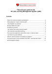
Flow Map eXplorer Quick User Guide Table of Contents 1. Usage..................................................................................................................................................... 2 1.1. Overview of the application interface .............................................................................................. 2 1.2. Menu Bar........................................................................................................................................... 3 1.3. Exploration Tool Bar.......................................................................................................................... 7 1.3.1. Free Flows mode ........................................................................................................................... 7 1.3.2. Top Flows mode ............................................................................................................................ 8 1.3.3. Global Flows mode........................................................................................................................ 8 1.3.4. Top Hubs ....................................................................................................................................... 9 1.4. Settings Tool Bar ............................................................................................................................. 10 1.5. Map Panel ....................................................................................................................................... 11 2. Data and Map Input ............................................................................................................................ 12 2.1. Flow Data ........................................................................................................................................ 12 2.2. Regional Data (Optional) ................................................................................................................. 14 2.3. Map Files ......................................................................................................................................... 15 2.3.1. Projection .................................................................................................................................... 16 2.3.2. DBF Fields .................................................................................................................................... 16 3. Application Configuration File ............................................................................................................ 17 3.1. Header............................................................................................................................................. 18 3.2. Data Source ..................................................................................................................................... 18 3.3. Layout.............................................................................................................................................. 19 3.4. Locales............................................................................................................................................. 20 3.5. Using Background Map and Google Maps API Key ......................................................................... 20 3.6. Stories ............................................................................................................................................. 21 3.7. Presets............................................................................................................................................. 21 4. Basic steps to configure Flow Map with Your Data and Map ............................................................. 24 5. The Flow map Package........................................................................................................................ 29 6. Server Installation ............................................................................................................................... 29 7. Requirements for Running Flow Map eXplorer on Client Side ........................................................... 30 8. Running Flow Map eXplorer Locally ................................................................................................... 30 1 1. Usage 1.1. Overview of the application interface Flow map eXplorer can have several layouts, which you can configure. However the most typical layout looks like the one shown in Figure 1. Figure 1: Start-up application in Full-Screen mode and Vertical Layout The layout comprises three parts. The top part includes a menu bar (to the left) and two tool bars (to the right). The middle part includes three panels: a histogram panel (to the left), a map panel (in the center) and a story panel (to the right). The story panel is collapsed as default if there is no story loaded at start up. The bottom part is an animation control bar which is shown up if there is more than one time steps in the data input. Otherwise it will be disappeared. 2 1.2. Menu Bar The menu bar contains four menus File, Settings, View and Help as described below. File o Manage Data. Normally this function is disabled. In most of the case you may ignore it. It is only enabled when (1) you stores flow data in many different files (e.g. one file for each country which store all trade flow data (export and import) of one commodity for a period from 1980 to 2010) and (2) loading flow data is done through a configuration file, named dataConfig.xml, which allows you select which files are loaded. For example, at start up you may load total trade flow data of three countries USA, Japan and Germany. Then after that you can use this function to load trade flow data of other countries. Settings o Exploration - Opens the Flows and Hubs Information panel which includes several tabs displaying information of active flows and hubs. o Language - Selects display language of the application. o Map Flow - Opens the Flow Settings panel which allows you to set properties of flows such as flow width scale, flow indent as shown in Figure 2 Figure 2: Flow Settings panel 3 Figure 3: Flow headers are increased to be more visible by increasing the flow header size threshold Figure 4: Time Graph, Top Hub Settings panel 4 Time Graph, Top Hubs - Opens the Time Graph, Top Hubs Settings panel which allows you to set properties of time graph glyphs and circle glyphs as shown in Figure 4 Region, Background Map - Opens the Region, Background Map Settings panel (as shown in Figure 5) which allows you to turn on/off the background map and set properties of regions such as the border colour of origins and destinations. Figure 5: Region, Background Map Settings panel Figure 6: An example of choosing Microsoft Road as a background map 5 o Regional Tooltip Indicators – Opens the Regional Tooltip Indicators panel (as shown in Figure 7) which allows you to select which indicator values should be displayed in a region tooltip. Figure 7: Regional Tooltip Indicators panel o Miscellaneous – Opens the Miscellaneous Settings panel (as shown in Figure 8) which allows you to select if growth-rate data should be calculated and merged into the regional dataset. Figure 8: Miscellaneous Settings panel View o o o Help o o Map Widgets Map Navigation - Turns on/off the Map Navigation control. Colour Legend - Turns on/off the Colour Legend control. Switch Layout Single View - Hides the histogram panel and expand the map panel. Double View Horizontal - Switches to horizontal layout. Vertical - Switches to vertical layout. Full-screen – Expands the application window to occupy the entire screen. Getting Started – Opens Getting Started window which shows a brief overview about the application. About – Opens About window which shows author and license information. 6 1.3. Exploration Tool Bar The Exploration tool bar is one of the important controls of the application. It contains four icons which correspond to four main operations and three modes (free flows mode, top flows mode and global flows mode) in exploration of flow data as described below. The application can be in one of the three modes at a time. 1.3.1. Free Flows mode Free flows mode is the mode which allows you to freely select flows to display on the map panel. To go into this mode, click on the Free Flows icon . When going into this mode, the application displays the Origin and Destination control to the right of the map panel. At the same time it displays the Free Flows panel which shows information of flows being displayed on the map in this mode as shown in Figure 9. Figure 9: The Free Flows panel shows information of flows being displayed in the free flows mode. By clicking on icons or then clicking on a region, you can specify one region as an origin or a destination. To select multiple origins or destinations hold Ctrl key while clicking on regions. Then flows connecting between origins and destinations will be displayed on the map. In this mode the application also allows user to select flows to be displayed on the map by clicking on flows in the Flow Data tab (next to the ‘Flow Map’ tab). 7 To display or hide flows on the map panel in this mode, click on the On/Off button of the Free Flows icon. 1.3.2. at the bottom Top Flows mode Top Flows mode is the mode which allows you to explore the top flows (or a range of flows) of one or many origins. To go into this mode, click on the Top Flows icon . When going into this mode, the application displays the top flows of selected origins on the map. At the same time it displays the Top Flows panel which shows information of these top flows as shown in Figure 10. To select an origin for exploration of its top flows, click on a region on the map. To select multiple origins, hold Ctrl key while clicking on regions. Figure 10: The Top Flows panel shows information of the top flows of an origin. You then can use the slider bar on the top of the Top Flows panel to select the range of flows which should be displayed. To display/hide the inverse flows of the top flows, click on the Inverse button to the right of the Top Flows panel. To display or hide flows on the map panel in this mode, click on the On/Off button 1.3.3. at the bottom of the Top Flows icon. Global Flows mode Global Flows mode is the mode which allows you to explore the global top flows (or a range of flows) instead of top flows of selected origins as in Top Flows mode. To go into this mode, click on the Global Flows icon . When going into this mode, the application displays the global top flows on the 8 map. At the same time it displays the Global Top panel which shows information of the global top flows as shown in Figure 11. Figure 11: The Global Top panel shows information of global top flows. You then can use the slider bar on the top of the Global Top panel to select the range of flows which should be displayed. To display or hide flows on the map panel in this mode, click on the On/Off button at the bottom of the Global Flows icon. 1.3.4. Top Hubs Top Hubs is a function which allows you to explore the top regions, i.e. those are the largest sources or destinations of flows. When you click on the Top Hubs icon , the map panel will display circles which mark the top regions. The size of each circle represents the total volume of flows coming into or going out from the region on which the circle is placed. At the same time the application also displays the Global Top panel which shows information of the top regions as shown in Figure 12. You then can use the slider bar on the top of the Top Hubs panel to select the range of regions which should be marked by circles. To display or hide circles on the map panel, click on the On/Off button at the bottom of the Top Hubs icon. 9 Figure 12: The Top Hubs panel shows information of top hub regions. 1.4. Settings Tool Bar The Settings tool bar contains controls, as described below, corresponding to functions which you may use frequently. Background Map check box allows you to turn on/off the background Google map. Flow Settings button allows you to quickly access the Flow Settings panel to set properties of flows such as flow width scale, flow indent as shown in Figure 2. Inflow and Outflow check boxes allow you to select which flow directions (in-coming or out-going or both) you want to see on the map. These settings only work when you are in one of the following modes: Free Flows, Top Flows, or Top Hubs. 10 1.5. Map Panel The Map Panel is one of most advanced components of Flow Map eXplorer. It allows you to visualize both flow data and regional data at the same time. This, in many cases, can support users searching answers to questions, for example, why people tend to move from one region to another region through finding the correlation between the flow data and the regional data. For example, users may find out that regions with high level of income attract more people from other regions commuting to work, or regions having many universities attract more people moving to for their education. The Map Panel is implemented basing on our layered map architecture (see Figure 13). It includes several layers such as border map layer, region shape layer, flow layer, glyph layer and a back ground map layer which can be OpenStreetMap, Yahoo Map, Google Map or Bing Map. These layers can be turned on or off through setting panels according to the user's need. Figure 13: The Map Panel is based on the layered map architecture. It includes several map layers which can be turned on or off. 11 2. Data and Map Input 2.1. Flow Data The main data input of Flow map eXplorer is a flow data file which can be stored in one of the following formats. Format 1 – Interaction table format In this format, flow data is stored as a matrix. Data of one time step is stored in one work sheet of an excel file. The first cell in the first column stores flow type name and unit if needed (e.g. “Migration (persons)”, or “Migration (persons)”). The first column stores the region/country identifications (IDs) of source regions and the first row stores the region/country IDs of destination regions. These region/country IDs should match with region/country IDs in the dbf file as explained further later. Figure 14 shows an example of flow data which are stored in interaction table format. Figure 14: Commuting data among Sweden counties from 2005 to 2008 are stored in interaction table format Format 2 – eXplorer Unicode format. This format is the same format used in our Statistics eXplorer. The second column stores the region/country IDs of source regions and the third column stores the region/country IDs of destination regions. Next columns store values of flows from source regions to destination regions. With this format, you can store more than one flow data type in one file. For example you can store commuting data of men and women in one file, which we cannot do it with the interaction table format. Figure 15 shows an example of flow data stored in eXplorer Unicode format. 12 Figure 15: Commuting data among Sweden counties from 2005 to 2008 are stored in eXplorer Unicode format Important note: Flow data in this format can be saved as an Excel file (.xls or .xlsx) or a Unicode text file (.txt) through Microsoft Excel. Format 3 – Three-column list format. This format stored flow data in a way which supports fast data reading of large datasets. Flow data in this format is saved as csv files. To be able to use this format, you can use our online conversion tool (http://www.ncomva.se/flash/projects/FlowMap/FlowDataConversionTool/) to convert Excel flow data files in interaction table format as mentioned above or in three-column list format (as described below) to Csv format. Three-column list format is a format in which we stores flow data in three columns. The first column stores the region/country IDs of source regions, the second column stores the region/country IDs of 13 destination regions and the third column stores values of flows from source regions to destination regions. Data of one time step is stored in one work sheet of an excel file. Figure 16: Commuting data among Sweden counties from 2005 to 2008 are stored in three-column list format 2.2. Regional Data (Optional) To support better the analysis of flow data, the application allows you to input a regional data file. This file is optional and should be in our eXplorer Unicode format as shown in Figure 17. Note that when you use a regional data file, the region/country IDs (or codes) in the second column (i.e. CODE column) should match with the region/country IDs in the flow data file as well as the region/country IDs in the column of the dbf file which is specified for the region/country IDs (see Section 3.2). If the regional data file has a Name column at the third column (see Figure 17) then the names in this column are used for the names of regions/countries. Otherwise the application will base on what you specify in the dbfNameField attribute of the shapeFile tag in the configuration file to find out the column in the dbf file for region/country names as explained more in Section 3.2. 14 Figure 17: An example of a regional data file in our Unicode eXplorer format. The second column is the CODE column (or ID column) and is compulsory. The third column is the Name column and it is optional. 2.3. Map Files Flow map eXplorer uses the industry standard ESRI Shape file format as input for drawing maps. In this manual we give a short introduction to the files used, which are a subset of the full ESRI suite. ESRI shape maps are divided into several files, Flow map eXplorer uses only two of these, but we recommended to always keep the rest with eXplorer is alterations are needed using other software. Files used by Flow map eXplorer are: - .shp: The actual map file which contains all coordinates. It is used to draw shapes. .dbf: Data base file which contains information linked to each shape. It is used to link shapes to data. Additional files, not use by Flow map eXplorer: 15 2.3.1. .prj: Projection details .shx: Additional coordinate information Projection Although Flow map eXplorer does not use the .prj file, there are still restrictions in what coordinate space the shp file can be in. Flow map eXplorer can run in two different modes, either with a background map or without one. When the background map is enabled, the input shape projection has to match that of the Google API. - With Background Map: Geographic Coordinate System, World, WGS 1984 o A basic latitude/longitude un-projected setup. - Without Background Map: Any projection without precision limitations. 2.3.2. DBF Fields To allow Flow map eXplorer to match shape regions with data items there has to exist an identifier column in the dbf file. This column should contain the region/country IDs which are used in the ID column of the flow data file and regional data file (if any). For countries we commonly use the ISO 31661 alpha-3 (http://en.wikipedia.org/wiki/ISO_3166-1_alpha-3). The name of the identifier column must be specified in the dbfIdField attribute of the shapeFile tag in the configuration file as explained in Section 3.2. 16 3. Application Configuration File Flow map eXplorer uses a configuration file, named config.xml, to specify its data input, map shape input, story input as well as to configure various aspects of the application such as the layout, projection, flow width scale factor. An example of the configuration file is shown in Figure 18. Figure 18: An example of the configuration file The configuration file contains a number of parts as described below. 17 3.1. Header In this part, there are two tags: title and logo. The title tag allows you to specify the title of the application while the logo tag allows you to specify the logo which should be displayed to the top left corner of the application. The logo tag is optional; this means it can be removed if you do not need it. Figure 19: An example of the header part 3.2. Data Source This part includes several tags which allow you to specify flow data input, regional data input (which is optional) and map data input. First, you can specify the flow data input, which is compulsory, through the filename attribute of the flowDataFile tag as shown in Figure 20. Second, you can specify the regional data input, through the filename attribute of the regionDataFile tag. However, this tag is optional. This means if you do not have a regional data file you can remove this tag from the config.xml file. Third, you can then specify the map shape input, which is compulsory, through the shapeFile tag. This tag has the following three attributes: - mapName which is used for specifying the map file name (no file extension included), dbfIdField which is used for specifying the column in the dbf file for region/country IDs, and dbfNameField which is used for specifying the column in the dbf file for region/country names Note: You can use the same column in dbf file for both region/country IDs and region/country names. The last tag in this part is the projection tag where you can specify which projection should be used through the name attribute. The projection specified in this tag will be applied when the background map such as Google map, Bing Map, Open Street map are not used or disabled. There are two projections supported in Flow map eXplorer: Mercator projection and Unit projection. Figure 20: An example of the dataSource part 18 3.3. Layout Figure 21: An example of the layout part This part includes three tags: view tag, settingsPanel tag and storyPanel tag. With the view tag, you can specify which layout you want to use. There are three layouts supported in Flow map eXplorer: single layout, horizontal layout and vertical layout which are described above in Section 1.2. You should specify the layout based on the shape of the map used. If the map has horizontal shape, e.g. world map, then the horizontal layout is suitable for this type of map. If the map has vertical shape, e.g. Sweden map, then the vertical layout is suitable for this type of map. If you do not specify the layout, the vertical layout will be used. The settingsPanel tag has three attributes: extended, shownAtStartUp, and width. The extended attribute, which can be set to “true” or “false”, allows you to specify if the Exploration tool bar should be placed in the Settings panel or not (see Figure 22). Note: The Settings panel can be shown or hide through clicking on the small button in the middle of the left edge of the map panel in Figure 1. Settings button Figure 22: An example of the Settings panel without Exploration tool bar integrated 19 Similarly, the shownAtStartUp attribute, which can be set to true or false, allows you to specify if the Settings panel should be shown at start-up or not; and the width attribute allows you to specify the width of the Settings panel. If this attribute is not specified the width of the Settings panel is measured based on its content. The storyPanel tag has only one attribute policy, which can be set to one of the following three values: “auto”, “on”, “off”, to specify if the story panel (which is to the right of the application as shown in Figure 1) should be shown or not. If this tag is not specified the default policy is “auto”. This means the story panel is shown if there is a story specified in the story part (see Section 3.6). The layout part is optional. This means you can remove this part totally from the file or remove some tags inside this part. 3.4. Locales This part allows you to specify locales (or languages) that the application should use. Currently Flow map eXplorer supports only English. Other languages (e.g. French, Swedish) will be supported in near future. Figure 23: An example of the locales part 3.5. Using Background Map and Google Maps API Key Flow map eXplorer supports a number of background maps as listed below: OpenStreetMap, Microsoft Road, Microsoft Aerial, Microsoft Hybrid, Yahoo Road, Yahoo Aerial, Yahoo Hybrid, Blue Marble, Google Street, Google Satellite, Google Hybrid, Google Terrain. To be able to use Google Map in Flow map eXplorer on your website, you need to register for a Google Maps API key and put it in this part. Note from Google: The Google Maps API for Flash has been officially deprecated as of September 2, 2011. The API will continue to work until September 2, 2014. https://developers.google.com/maps/documentation/flash/intro. Please follow the instructions on the Maps API for Flash Key Request website if you need a new key. Once you have a google Maps API key from Google for your website you can specify it in the googleMapKey tag (see Figure 24). Please keep in mind that each of background maps comes with a specific license that needs to be understood. Open Street Map: http://www.openstreetmap.org/copyright Microsoft Bing Maps: http://www.microsoft.com/maps/product/licensing.aspx Yahoo Maps: http://info.yahoo.com/legal/us/yahoo/maps/mapsapi/mapsapi-2141.html IMPORTANT, READ THIS: Generally speaking, what these licenses say are that Open Street map can be used freely with no limitations, so if you are unsure, only use this one by removing the backgroundMapTypes tag (see Figure 24) from the config.xml file. Microsoft, Yahoo and Google all basically comes with the same terms of 20 use, that the site needs to be publically available and that you do not charge anyone for viewing the specific site. For any larger scale usage a contact has to be made to the specific provider. We urge you to look at the licenses so that you are aware of what they mean. If you do not want to use any background map type listed in Figure 24, just remove it from the list. The backgroundMap tag has three attributes: enabled, mapType, and visible. The enabled attribute, which can be set to “true” or “false”, allows you to specify if the application should have a background map or not. If the enabled attribute is set to “false” this means the application have no background map and the projection which is specified in the dataSource part will be used (see Section 3.2). The mapType attribute, which can be set to one of the background maps listed above, allows you to specify which map type you want to use as default; and the visible attribute, which can be set to “true” or “false”, allows you to specify if the background map is visible or not at start-up. Figure 24: An example of the background map part 3.6. Stories In this part, you can specify a list of stories you want to load into the application. Use story tag to specify each story. The first story in the list will be active (i.e. used) at start-up. This part is optional. This means you can remove it from the file. Figure 25: An example of the stories part 3.7. Presets This part allows you to specify some presets when the application starts. However it is optional. This means you can remove it or some tags of it from the file (in that case, the application will use the default values instead). 21 Figure 26: An example of the presets part The selectedFocus tag allows you to specify which region is selected as an origin at start-up. The DBFcode of the region should be used in this tag. The selectedIndicator tag allows you to specify which indicator of the merged regional dataset is selected at start-up. (The merged regional dataset is the dataset which is combined from a flow dataset and a regional dataset.). Index 0 means the first indicator; index 1 means the second indicator and so on. This tag is optional. This means if you do not use this tag then the default index selected at start-up is 0. The selectedFlows tag allows you to specify which flow directions are used. 0 means in-coming flow (or inflow) and 1 means out-going flow (or outflow). This tag is optional. If it is not used then the default selected flow is inflow. The arrow tag allows you to specify the distance from the centre of a region to two ends of a flow (i.e. an arrow in this application) coming in or going from that region and the scale factor of the flow width. You should specify the values in this part based on the geographic type of map. For example: If regions are municipalities, the distance can be 0.05 and the scale is 0.5. If regions are counties, the distance can be 0.3 and the scale is 2. If regions are countries, the distance can be 1 and the scale is 3. The hub tag allows you to specify the scale factor for circles representing hubs. The netValueMethod tag allows you to specify the way of calculation of net values. An example is “0-1” which means that net value is computed by the following formula: Net value = In-coming flow value – Out-going flow value And “1-0” means that Net value = Out-going flow value – In-coming flow value The usingNumberAbbreviation allows you to specify if the application should use number abbreviation in displaying number values. If this value is set to true, a number like “123,456,789” will be displayed as “123M” for short. The enableBilateralTrades tag allows you to specify if flow data is bilateral data. Bilateral flow data means the same flow from a region A to a region B has two different values; one is reported by A and another one is reported by B. 22 The barChartPanel tag allows you to specify the start index and the number of bars in the focus area of the bar chart. The regionTooltip tag allows you to specify which group of indicators should be shown in the region tooltip. 23 4. Basic steps to configure Flow Map with Your Data and Map Step 1 – Prepare map files If you want to use Flow map eXplorer with a new map you should put files (including a shape file and a dbf file) of the new map in the map folder of the application as shown in Figure 27. The shape file and the dbf file should have their file name extension as .bin (see Figure 27). .bin map folder Figure 27: the ‘maps’ folder in Flow map eXplorer folder Step 2 – Prepare a flow data file Flow data should have one of three formats as described in Section 2.1 Flow Data. If your dataset is not so large you should use either interaction table format or our eXplorer Unicode format. The csv format which is quite tricky should be only used when you have a very large dataset. Notes: 1. If you use the interaction table format you have to save your flow data as an Excel file (.xls or .xlsx). 2. If you use our eXplorer Unicode format you can save your flow data as an Excel file (.xls or .xlsx) or as a Unicode text file (.txt) through Microsoft Excel. You specify the flow data file in config.xml through <flowDataFile> tag as the following examples <flowDataFile fileName="data/flowData.xlsx"/> or <flowDataFile fileName="data/flowData.txt"/> Note: To edit config.xml file, you can use Notepad or Notepad++ (a free tool which can be downloaded at http://notepad-plus-plus.org/). 24 Step 3 – Select a dbf field for region codes (source region codes and destination region codes) Code column Name column Figure 28: Columns of country codes and country names in a dbf file of a world map Code column Figure 29: Code column in a dbf file of a NUTS2 map Figure 30: Right click on a .dbf.bin file and select Microsoft Excel to open it 25 A dbf file normally has a region code column, which contains region codes, and a region name column, which contains region names, as shown in Figure 28. Some dbf file has a region code column but does not have a region name column, for example the dbf file of a NUTS2 map shown in Figure 29. Note: To open a dbf file, you can use Microsoft Excel as shown in Figure 30. You have to choose a column in the dbf file for region codes and a column for region names. These two columns can be different or be the same. Region codes are used in the flow data file to specify flows from a source region to a destination region. Region names are used to show the name of region codes to users. Then you have to specify the column code and the column name in config.xml file through <shapeFile> tag as shown in the following examples. Figure 31: Country names specified in CNTRY_NAME column in the dbf file of a world map are used to specify source codes and destination codes in a flow data file under eXplorer Unicode format Figure 32: Country names specified in CNTRY_NAME column in the dbf file of a world map are used to specify source codes and destination codes in a flow data file under interaction table format Example 1: 26 The following example uses CNTRY_NAME column in the dbf file of a world map (see Figure 28) for both dbfIdField and dbfNameField. <shapeFile mapName="maps/world" dbfIdField="CNTRY_NAME" dbfNameField="CNTRY_NAME"/> Then source code column and destination code column in the flow data file under eXplorer Unicode format should use country names in CNTRY_NAME column in the dbf file to specify countries as shown in Figure 31. Figure 32 shows the flow data file under interaction table format. Example 2: The following example uses CODE column for dbfIdField and CNTRY_NAME column for dbfNameField. <shapeFile mapName="maps/world" dbfIdField="CODE" dbfNameField="CNTRY_NAME"/> Then source code column and destination code column in the flow data file under eXplorer Unicode format should use country codes in CODE column in the dbf file to specify countries as shown in Figure 33. Figure 34 shows the flow data file under interaction table format. Figure 33: Country codes specified in CODE column in the dbf file of a world map are used to specify source codes and destination codes in a flow data file under eXplorer Unicode format 27 Figure 34: Country codes specified in CNTRY_NAME column in the dbf file of a world map are used to specify source codes and destination codes in a flow data file under interaction table format Step 4 – (Optional) Prepare a regional data file If you want to use a regional dataset with a flow dataset to support analysis of flow data it is possible. The regional data file should be in eXplorer Unicode format. You specify the regional data file in config.xml through <flowDataFile> tag as the following example <regionDataFile fileName="data/regionData.txt"/> Step 5 – Choose a region which will be selected at start-up Flow map eXplorer normally starts in the top flow mode in which it shows top inflows and outflows of a region. You can specify the region you want the application focus on at start-up by using <selectedFocus> tag as shown in the following examples: <selectedFocus code="Belgium"/> (if dbfIdField="CNTRY_NAME") or <selectedFocus code="BE"/> (if dbfIdField="CODE") 28 5. The Flow map Package The distributed Flow map eXplorer package contains several files and folders as shown in Figure 35. The most important file is the .swf Flash file, which contains the actual Flow map eXplorer Flash application. Here, all the logic of Flow map eXplorer is processed. All content, from maps and data to application title and logo are defined outside of the compiled swf, allowing these features to be changed without the recreation of the application .swf Flash file. The main folders include ‘data’, ‘maps’, and ‘stories’. The ‘data’ folder is where you can put flow data files and regional data files. The ‘maps’ folder is where you can put map files (.shp.bin and .dbf.bin). The ‘stories’ folder is where you can put story files. Figure 35: Typical files and folders of a Flow map package 6. Server Installation Flow map eXplorer is mainly independent of the type of server. It uses no server side backbone and no database. The only sensitive settings are the allowance of loading certain MIME types as files from the server to the application. These are common file types, .swf (flash application), .bin (maps), .xml (Meta data) and .txt (data), which by default are allowed by almost all web servers. This makes installation of Flow map eXplorer as simple as placing the files in a web enabled folder, and it will work immediately. Flow map Statistics eXplorer is distributed in a packaged form, commonly as a single .zip file, which contains all files needed by the application – see Figure 35. 29 7. Requirements for Running Flow Map eXplorer on Client Side Flow map eXplorer is developed with the GAV Flash toolkit and framework that use Adobes’ Flash and Flex library. Flow map eXplorer requires Adobe Flash Player, a plug-in that is often automatically prompted when visiting Flash based websites. Statistics eXplorer requires Flash version 10, and it is highly recommended to always have the latest update installed. This manual gives an introduction and overview of the Statistics eXplorer package that is sent to the operator for installation on a web server. Adobe Flash Player: http://www.adobe.com/products/flashplayer/ Adobe Flex: http://www.adobe.com/products/flex/ 8. Running Flow Map eXplorer Locally If you want to test Flow map eXplorer locally (by opening index.html files in the package with some web browser such as Internet Explorer or Firefox), you should first go to the web site below to register the location (e.g. C:\FlowMap) where you will run the application (see Figure 36). http://www.macromedia.com/support/documentation/en/flashplayer/help/settings_manager04.html Figure 36: Sign up for running a flash application locally 30