1
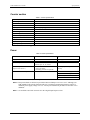
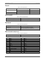
USB-1024HLS User's Guide
Specifications
Counter section
Table 2. Counter specifications
Pin name (Note 4)
Counter type
Number of channels
Input source
Input type
Resolution
Schmidt trigger hysteresis
Input leakage current
Maximum input frequency
High pulse width
Low pulse width
Input low voltage
Input high voltage
CTR
Event counter
1
CTR screw terminal
TTL, rising edge triggered
32 bits
20 mV to 100 mV
±1 µA
1 MHz
500 ns min
500 ns min
0 V min, 1.0 V max
4.0 V min, 15.0 V max
Note 4: CTR is a Schmitt trigger input
Power
Table 3. Power specifications
Parameter
Conditions
Specification
Supply current (Note 5)
Input power requirements (Note 6)
USB +5 V power available
No load
80mA typ, 135 mA max
4.75 V min, 5.25 V max
4.4 V min, 5.25 V max
USB +5 V power
output current (Note 7)
USB +5 V over-current protection
Measured at "USB +5 V" screw
terminals (pins 10, 14, and 30)
Connected to:
! Self-powered hub
! Externally-powered root port hub
Resettable fuse
[350 mA] – [total output source
current]
Hold current: 350 mA, typical
Trip current: 700 mA typical
Trip/recovery time: 100 mS, max
On resistance: 1.3 Ohms max
Note 5: This is the total (no load) current requirement for the USB-1024HLS.
Note 6: Bus-powered hubs are allowed to provide downstream USB power as low as 4.4 V. Although your
USB-1024HLS will typically function at this 4.4 V minimum, guaranteed performance requires a
minimum power supply voltage of 4.75 V. All self-powered and root port hubs will meet this 4.75 V
minimum.
Note 7: See available source/sink current level in the "Digital input/output" section.
4-2