1
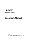
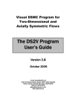
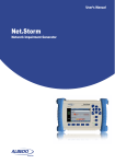
User's Guide
TL-SL3226P
24+2G Gigabit Managed Switch
Rev 1.0
E-mail: [email protected]
Trademark, Copyright statement
Table of contents
is the registered trademark of Shenzhen TP-LINK
Technologies Co., Ltd. All rights reserved, contents may be revised
Checklist...............................................................................................1
without prior notice. No part of this publication may be reproduced in any
Chapter 1
form or by any means or used to make any derivative such as translation,
1.1
Usage..........................................................................................1
transformation, or adaptation without permission from Shenzhen
1.2
Assumpsit....................................................................................1
TP-LINK Technologies Co., Ltd. See our web site for more details:
1.3
Overview of this User's Guide.....................................................2
http://www.tp-link.com.
Chapter 2
About this User's Guide...................................................1
Introduction.......................................................................2
2.1
Overview of the product..............................................................2
2.2
Features and specification..........................................................3
2.2.1 Features......................................................................................3
2.2.2 Specification................................................................................4
Chapter 3
3.1
Installation........................................................................5
Installation...................................................................................5
3.1.1 Desktop or Shelf Installation.......................................................5
3.1.2 Rack Installation..........................................................................5
3.1.3 Power On....................................................................................6
3.2
Connecting the Switch................................................................7
3.2.1 Front Panel..................................................................................7
3.2.2 Rear Panel..................................................................................8
3.2.3 Optional Extension Modules.......................................................9
3.3
Remarks....................................................................................10
Chapter 4
4.1
TELNET/Out-of-Band Management...............................11
Introduction...............................................................................11
4.2
How to connect TELNET...........................................................12
4.3
How to connect Out-of-Band.....................................................13
4.4
The interface and operating way of TELNET/Out-of-Band........14
4.4.1 Configure System......................................................................17
4.4.2 Port Management......................................................................20
4.4.3 Network.....................................................................................24
4.4.4 Spanning Tree protocol.............................................................25
4.4.5 IEEE802.1X protocol.................................................................26
4.4.6 VLAN Management...................................................................27
4.4.7 Configure Trunk.........................................................................28
Chapter 5
WEB Management.........................................................29
5.1
Introduction...............................................................................29
5.2
Connection of WEB Management.............................................29
Annex A
RJ-45 Plug/Connector Pin Specification.........................34
Annex B
Default Configuration of the switch.................................36
TL-SL3226P
24+2G Gigabit Managed Switch User's Guide
TL-SL3226P
24+2G Gigabit Managed Switch User's Guide
Checklist
1.3 Overview of this User's Guide
Open the box and carefully unpack the TL-SL3226P. You should have all the
Chapter 1
About this User's Guide
items on the following checklist:
Chapter 2
Introduction. Describes the switch and its features
Chapter 3
Installation. Helps you to get started with the basic installation
!
One TL-SL3226P Switch
!
One AC power cable
!
One Serial cable
!
One User's Guide (CD or Presswork)
!
Two mounting brackets and screws
If any item is missing, contact the retailer where you purchased the TL-
of the switch
Chapter4
TELNET/Out-of-Band Management.Describes how to manage
the switch through TELNET/Out-of-Band Management
Chapter 5
WEB Management
Annex A
RJ-45 Plug/Connector Pin Specification
Annex B
Default Configuration of the switch
SL3226P for assistant.
Chapter 2
Chapter 1
About this User's Guide
Introduction
2.1 Overview of the product
Thank you for purchasing TL-SL3226P 24+2G Gigabit Managed Switch.
TL-SL3226P switch fully complies with IEEE802.3 Ethernet standard, its
The TL-SL3226P provide powerful management functions. With the
standard 19-inch size and intelligent management make it suitable for small,
features of high-performance, easy-to use and economic, the TL-SL3226P
middle and large networks.
is the ideal choice for you.
TL-SL3226P switch provides powerful management functions, including the
system, port, network, Spanning Tree protocol, IEEE802.1X protocol, VLAN,
1.1 Usage
Trunk, IGMP Snooping, SNMP protocol, priority and security etc.
This User's Guide tells you how to use your TL-SL3226P.
TL-SL3226P switch provides multiple management method: SNMP, Web,
1.2 Assumpsit
Telnet and Console (RS232).
The TL-SL3226P indicated in this User's Guide is the TL-SL3226P 24+2G
TL-SL3226P switch provides two independent extension slots, which
Gigabit Managed Switch.
support 100/1000M module card and GBIC. This modular structure protects
user investment and makes the switch more versatile.
TL-SL3226P
2.2
24+2G Gigabit Managed Switch User's Guide
Features and Specification
TL-SL3226P
Support static priority and IEEE802.1p class of service with 2-level
!
priority mode
2.2.1 Features
!
Fully comply with IEEE802.3 standard
!
Full and half-duplex for both 10Mbps and 100Mbps connections.
!
Support IEEE802.3x flow control for full-duplex mode and collisionbased backpressure for half-duplex mode
!
Use non-blocking store-and-forward shared-memory architecture
!
24 10/100BaseT/TX RJ-45 ports with auto-MDI/MDIX
!
Provide 2 independent extension slots support 100/1000M module
card and GBIC
!
Support the port N-Way auto-negotiation function, automatically
24+2G Gigabit Managed Switch User's Guide
!
Support Static MAC address management and MAC address Binding
!
Provide the configuration function of port security, broadcast storm
control and port sniffer
Provide per port egress/ingress rate control function and the minimum
!
granularity is 64kbps
Provide static IP address configuration and dynamic IP parameters by
!
DHCP
Support firmware upgrade, configuration backup and restore by TFTP
!
2.2.2 Specification
negotiate the speed and duplex mode between two devices
!
Provide 6K MAC address space
!
Support MAC address learning and aging with programmable age
Standard
!
Provide SNMP, Web and Telnet/Console management
!
Support SNMPv1, SNMPv2c
!
Support SNMP MIB-II, Ethernet-like MIB, Bridge MIB, TP-LINK
LED
Enterprise MIB
indicator Each port
Dimension
!
Support RMON Statistics, History, Alarm and Event group
Compliant with IEEE802.3, IEEE802.1D,
IEEE802.1Q and IEEE802.1X
24 10/100M RJ-45 ports with auto-MDI/MDIX
2 independent 100/1000M extension slots
One console port (RS232)
IEEE802.1Q VLAN mode
Port-based VLAN mode
10Base-T: CAT 3 or above CAT 3 UTP/STP
100Base-TX: CAT 5 UTP/STP
100Base-FX: MMF, SMF
1000Base-T: CAT 5 UTP/STP
1000Base-SX: MMF
1000Base-LX: SMF or MMF
Power on
Two indicators: Link/Act and 10/100Mbps
440mm 260mm 44mm (W x H x L)
Environment
Operating temperature: 0oC ~ 40oC
!
Support IEEE802.1D Spanning Tree protocol
!
Support IEEE802.1X Port-Based Network Access Control protocol
Power
Storage temperature: -20oC ~ 70oC
Operating humidity: 10% ~ 90% RH
Storage humidity: 5% ~ 90% RH
110-260V~ 50-60Hz
Port
time
!
Provide IGMP snooping function
!
Provide maximum 26 port-based VLAN and 256 IEEE802.1Q VLAN
!
Provide maximum 7 trunk groups of up to 4 member ports within 26
VLAN Mode
Network Medium
ports
and connect to RADIUS
Power
TL-SL3226P
Chapter 3
24+2G Gigabit Managed Switch User's Guide
24+2G Gigabit Managed Switch User's Guide
TL-SL3226P
Installation
3.1 Installation
Follow these steps to install the switch:
!
The surface must support at least 5kg
!
The power source must be within 1.5m
!
Check the power cable to make sure the connection to AC power
Slot 1
Slot 2
1000M
Act
!
10/100M
FDX/Col
TX
RX
Link
Act
1
3
2
4
5
7
9
11
13
15
10
12
14
16
Link/Act
17
19
21
23
20
22
24
100M
TL-SL3226P
6
8
Leave enough space for the ventilation
Power
18
Console
24+2G Gigabit
Managed Switch
3.1.1 Desktop or Shelf Installation
1.
Put the TL-SL3226P on the big and stable desktop, bottom up.
2.
Attach the cushioning feet on the bottom at each corner of the device.
3.
Upturn the device, put it on the desktop.
3.1.2 Rack Installation
The TL-SL3226P can be mounted in an EIA standard size 19 inch rack.
1.
Attach a mounting bracket to each side of the TL-SL3226P with the
screws provided.
2.
Sl ide the TL-SF3226P into the Rack.
3.
U se the screws to secure the TL-SL3226P to the Rack.
Figure 3-1 Rack Installation
3.1.3 Power On
The TL-SL3226P can be used with the power source in the range of 110 to
260VAC, 50 to 60Hz.
The internal power system of the TL-SL3226P can automatically adjust the
operating power-pressure according to the power-pressure input. The
POWER LED will be light when power on.
Caution:
As a precaution in the event of a power failure, unplug the switch. When the
power resumed, plug the switch back in.
24+2G Gigabit Managed Switch User's Guide
TL-SL3226P
3.2
TL-SL3226P
24+2G Gigabit Managed Switch User's Guide
connection port with PC when Out-of-Band management.
Connecting the Switch
3.2.1 Front Panel
There are 2 extension module slots, 24 10/100Mbps ports, one console
Power LED
!
Located between the console port and 24 normal ports, the power LED will
(RS232) port and LED indicators on the front panel of the TL-SL3226P.
be always green when power on. Or else, please check the power
Slot 1
1
Slot 2
1000M
Act
10/100M
FDX/Col
TX
3
5
7
9
11
13
15
17
19
21
23
100M
Link
Act
TL-SL3226P
RX
Link/Act
Power
2
4
6
8
10
12
14
16
18
20
22
24
connection.
Console
24+2G Gigabit Managed Switch
Figure 3-2 Front Panel of the TL-SL3226P
100Mbps LED (Speed LED)
!
When a normal port connects to 100Mbps equipment, the responding LED is
!
Module Slot
orange. An unlit LED indicates a connection speed of 10Mbps.
The module slots can connect 100M/1000M module card and GBIC card.
Link/Act (Connection LED)
!
!
24 10Base-T/100Base-TX RJ-45 ports
All ports can auto-negotiate between 10Mbps or 100Mbps and full or half-
The LEDs are lit when there is a secure connection to a device at any of the
ports.
duplex. You can configure the speed, duplex mode, flow control, broadcast
storm control and security control through kinds of manage-ment way such
The flash LED indicates data transmission at the responding port.
as SNMP, Web, Telnet or Out-of-Band management.
3.2.2
There is one LED on each side of every port. Link/Act LED on the left is green.
100Mbps LED on the right is orange.
Rear Panel
The rear panel of the TL-SL3226P contains a power connector and a port for
ground connection.
Link/Act
110-260V ~ 50-60Hz 0.6A
Figure 3-4 the Rear Panel of the TL-SL3226P
Figure 3-3 one port of the TL-SL3226P
!
Console port
The Console port or RS232 port on the right of the front panel is the
!
Power connector
The AC power connector is a standard three-pronged connector that
TL-SL3226P
24+2G Gigabit Managed Switch User's Guide
TL-SL3226P
supports the power cord. Plug-in the female connector of the provided power
Model No.
Standard
24+2G Gigabit Managed Switch User's Guide
Interface Network Media
cord into this socket, and the male side of the cord into a power outlet.
Supported input voltage range from 110 to 260VAC at 50-60Hz.
!
Maximum Transfer
Distance
TL-SM201U
100Base-TX
RJ-45
TL-SM201CM
100Base-FX
SC
The port for connection to the ground
Cat 5 UTP/STP
50/125 um MMF
62.5/125 um MMF
There is a port on the left of the panel for the connection to the ground.
3.2.3 Optional Extension Modules
100m
2000m
TL-SM201CS-20 100Base-FX
SC
9/125 um SMF
20000m
TL-SM201CS-40 100Base-FX
SC
9/125 um SMF
40000m
TL-SM201CS-60 100Base-FX
SC
9/125 um SMF
60000m
There are two module extension slots on the front panel of the TL-SL3226P
as the following figure.
TX
TL-SM301 Gigabit series module
!
RX
1000M
100M
Act
Link
Link/Act
10/100M
10M
Model No.
Standard
Interface
Network Media
TL-SM301U
1000Base-T
RJ-45
Cat 5 UTP
TL-SM301CM
1000Base-SX
SC
50/125 um MMF
Maximum Transfer
Distance
FDX/Col
FDX/Col
Figure 3-5 Module of the TL-SL3226P
When you install any of the modules, you must turn off the power at first. After
TL-SM301CS
1000Base-LX
SC
100m
62.5/125 um MMF
550m
9/125 um SMF
10000m
you take out the board on the slot, put the module into the extension slot. The
TL-SL3226P can auto-identify the module and configure automatically.
Caution:
The TL-SL3226P can use with TL-SM201 100M series modules, TL-SM301
Gigabit series modules and TL-SM301GB GBIC cards.
The extension slots with UTP module can support auto-negotiation and auto
MDI/MDIX. These two slots are independent, never conflicting with other
!
TL-SM201 100M Series Module
normal ports.
3.3
!
Remarks
Pay attention to the stability when you put the TL-SL3226P. It's serious
if the TL-SL3226P drops.
TL-SL3226P
!
24+2G Gigabit Managed Switch User's Guide
TL-SL3226P
24+2G Gigabit Managed Switch User's Guide
The TL-SL3226P can start to work with the correct power supply.
Out-of-Band Management manages the Switch locally through the console
Please confirm whether the power supply is accordant to the
port, without occupying the bandwidth.
requirements of the TL-SL3226P.
!
In order to avoid the risk of the power-attach, don't open the shelf of
the TL-SL3226P when it works. Don't open the shelf even without
management contents are same. Both of them are to configure the Switch's
characters.
power.
!
Though TELNET and Out-of-Band have different presentation, their
When the TL-SL3226P is connecting with the working stop, server,
hub or other switches, the network cord must be less than 100m if the
4.2
network cord is UTP.
Connect the management workstation to the management port on the
!
You must use Cat 3 or above UTP for 10Base-T Ethernet.
Switch. You can directly use TELNET commend on the commend DOS
!
You must use Cat 5 UTP for 100Base-TX Ethernet.
prompt in the Windows Attachment.
!
The module decides the operating speed of the extension slot. The
100M Module can work in 100M situations, while the 1000M modules
can work in 1000M networks.
!
When the TL-SL3226P is working, the network cord can be put into
How to connect TELNET
The parameter following the TELNET commend is the IP address of the
Switch which can be revised to adapt to the network. However, when you
reuse TELNET to access, the parameter will be the Switch's IP address
newly set.
the port or put out from the port randomly, without breaking the
!
!
operating of the TL-SL3226P.
There is limit to the users accessing times through TELNET, maximum 3
Before clean the TL-SL3226P, please unplug the power adapter. Don't
times. There is also time limit for the connection. The connection will be
clean with liquid.
automatically broken if there is no operation in a limit time.
Don't put the TL-SL3226P near water or humidity; avoid water or
humidity air into the shelf.
!
Avoid the dust and strong electromagnetism.
Chapter 4
4.1
TELNET/Out-of-Band Management
Introduction
Through TELNET you can realize Remote Log in to manage the Switch.
Furthermore, maximum 5 users can access to the Switch through TELNET
at one time.
Remark:
Only the PC connecting to the management port can configure the Switch
through TELNET or WEB.
TL-SL3226P
4.3
24+2G Gigabit Managed Switch User's Guide
How to connect Out-of-Band
Out-of-Band Management needs a terminal or a HyperTerminal.
First, connect the Switch's console port with the PC's console port by the
console cord. Then, run HyperTerminal. Refer to the following figure to
TL-SL3226P
24+2G Gigabit Managed Switch User's Guide
HyperTerminal Private Edition. The configuration way is similar with that on
Windows.
4.4 The interface and operating way of TELNET/Outof-Band
configure the HyperTerminal.
No matter through TELNET or Out-of-Band Management, the users have
two rights:
!
Admin: the control right to manage the Switch
!
Guest: the read right for part of objects Admin visits.
Caution
Since Guest account has the read right only for some pages, there will be a
prompt to remind the user no right for reversion when the Guest account
want to configure the active the Switch. When the account wants to enter
SNMP menu, Security menu, IEEE802.1X protocol menu, file transmission
menu and reset menu of the system configuration menu, the account will be
reminded no right to enter.
Because the basic content of TELNET and Out-of-band Management
Figure 4-1 Console configuration
through the Console port is as same as each other, we introduce them
together.
The speed of the console port is 9600bps. The data bit is 8 bit. There is no
Parity Test and flow control. The Stop bit is 1.
After you use the correct user's name and password (the default user's name
and password are supervisor), you will log on the interface of TELNET/Out-
If there is no HyperTerminal in the system, you can setup the HyperTerminal
software from the system setup disk or download from the website such as
of-Band Management.
TL-SL3226P
24+2G Gigabit Managed Switch User's Guide
The management interface is the menu drive. After you log on, you will in the
TL-SL3226P
24+2G Gigabit Managed Switch User's Guide
table, static address table and filter address table.
first menu as following:
The Spanning Tree protocol includes the Switch configuration (Open/Close
Spanning Tree, Network Bridge Priority) and port configuration. (Such as
port priority, situation).
IEEE802.1X protocol includes Switch configuration, port configuration, force
authorized table, force unauthorized table and authorized address table.
VLAN Management includes VLAN mode configuration (Port-based VLAN,
IEEE802.1Q Tag VLAN and VLAN Disable), VLAN configuration and MTU
VLAN team.
Figure 4-2 Main Menu
!
Illumination:
Trunk Configuration is to configure and check Trunk.
IGMP includes IGMP Snooping Set and IPMC Group Member Info.
System Configuration includes system information such as
SNMP protocol includes SNMP agent situation, SNMP team name table
software/hardware version, module information, switch parameter such as
(such as access mode, situation), SNMP host table (such as IP address,
broadcast storm filter mode, file transmission, save and reset.
team name, situation), SNMP Trap purpose table (purposed IP address, port,
Ports Management includes port parameter (open/close flow control, port
situation), and SNMP system event.
default VID, port security), port mirror (two types: direction mode mirror and
Priority Management includes Port priority, priority mapping, and priority
flow mode mirror), port description (use character string to describe ports),
configuration.
port statistic (the statistic information of tag forwarding, receiving and
conflicting), port situation (connection situation, port speed, duplex mode)
Security Configuration menu is used to configure the user managing the
and port bandwidth (entrance bandwidth and exit bandwidth).
Switch (such as user's name, password, situation).
Network includes address parameter (the Ethernet address of the Switch, IP
Help is used to check the usage of kinds of control button (such as direction
address, NetMask, Gateway, etc), maximum aging time, Dynamic address
button, TAB button).
TL-SL3226P
24+2G Gigabit Managed Switch User's Guide
TL-SL3226P
24+2G Gigabit Managed Switch User's Guide
The assumpsit of normal control button in the operating interface is as
following:
<Arrow Key>= Direction Button: up, down, left, right moves cursor
<Tab> =Tab Button: move the cursor to the next stay place
<W>, <w> = W, w Button: move the cursor up
<S>, <s> = S, s Button: move the cursor down
<A>, <a> = S, s Button: move the cursor left
Figure 4-3 System Configuration
<D>, <d> = D, d Button: move the cursor right
<Esc> = Esc Button: exit the current menu
<Enter> = Enter Button: enter the next sub-directory or active the revision
<Space> = Space Button: switch the choice
<Backspace> = Backspace Button: delete one letter
<^U> = press U button after press Ctrl button (Ctrl + U): active the revision
Remarks:
!
System Information
When you configure System Information, only System Name, System
Contact and System Location can be changed. Others of System
Information are only for read.
data
<^A> = press A button after press Ctrl button (Ctrl + A): choose all letter
where the cursor locates
Remark:
!
Module Information
1)
If yo u use modules, you can configure the responding module slot.
Slot 1 Port 25
Slot 2 Port 26
The revised configuration won't be effect without activation. The effect
configuration is effective before the next startup. In order to effect the
2) If you install modules, the module information will be showed according
configuration after next startup, you need to enter into the SAVE and RESET
to the specific modules.
menu of System configuration menu to save the configuration.
100M UTP module: 100BASE-TX
100M Fiber module: 100BASE-FX
4.4.1 System Configuration
Gig abit UTP module: 1000BASE-T
Gig abit Fiber module: 1000BASE-LX/SX
TL-SL3226P
24+2G Gigabit Managed Switch User's Guide
TL-SL3226P
2) When downloading TFTP, TFTP server must have the files for updating.
!
Switch Parameters
1)
Assigned Managed Port: can be any port or all ports from P1 to P26.
Only the workstation connecting to the Assigned Managed Port in the
3)
You must guarantee the TFTP server in operating.
4)
To break the download is not allowed during the TFTP download. Or
else the Switch may be out of the way.
Switch can manage the Switch. The default is All ports.
2)
3)
24+2G Gigabit Managed Switch User's Guide
Broadcast Strom Filtering Mode: have six choices: 5%, 10%, 15%,
Save Reset
20%, and 25%.
!
The configuration of parameters won't be effect until you activate the
When you reset to factory situation, all parameters except IP address can be
changes. When you press Ctrl + U, the Switch will list
configured to factory configuration.
you want to activate the changes (Y/N)?
Are you sure
. Y for confirmation, N for
cancel.
!
File Transfer
1)
Transfer types are Update System, Backup Switch Config and Updata
4.4.2 Port Management
Switch Config.
Updata Switch System:
Figure 4-4 Port Management
Through the program files using by TFTP server to update the Switch,
download the program files provided by TFTP server into the Switch to
Ports parameters:
realize the software update.
In the IEEE802.1Q Tag VLAN mode, there are two pages of port parameters
as figure 4-3 and figure 4-4. In the figure 4-3, when the cursor is on the
Backup Switch Config:
Speed/Duplex, the interface as figure 4-4 will exist when you move the
Upload the configuration files of the Switch to TFTP server to store the
cursor right.
configuration parameters of the Switch.
In the Port VLAN mode or VLAN Disable mode, there is only one page of port
Updata Switch Config:
parameters as figure 4-5.
download the configuration files for the Switch from TFTP server to update
the Switch configuration.
The Port Security of Port 2 in the above figure is not configurable because
TL-SL3226P
24+2G Gigabit Managed Switch User's Guide
TL-SL3226P
24+2G Gigabit Managed Switch User's Guide
the IEEE802.1X protocol of Port 2 has been configured to be Enable. Please
10FD: 10Mbps, Full-Duplex
note Port Security, Trunk and IEEE802.1X protocol are mutually exclusive.
100HD: 100Mbps, Half-Duplex
In other word, when you configure one of them, other two can't be configured.
100FD: 100Mbps, Full-Duplex
State
Two independent modules
The port can be used when the State is Enable, while the port is prohibited
The operating mode of two independent modules is different according to
when the State is Disable. The Switch will discard the packets from the port.
different module.
!
Port Security
When you configure the Port Security of a port to be Enable, the port won't
There are four types of the modules:
1)
100M fiber module (such as TL-SM201 series)
learn any new MAC address. Furthermore, the port only transfers the Data
Auto: auto-negotiation
Tag accordant to requirements. Other Tags will be discarded. When the Port
100FD: 100Mbps, Full-Duplex
Security of a port is Disable, the port will automatically learn any new MAC
address and transfer Tags received.
2)
100M Twisted-Pair module (such as TL-SM201U)
Auto: auto-negotiation
!
10HD: 10Mbps, Half-Duplex
Flow Control
10FD: 10Mbps, Full-Duplex
Disable (default): The port won't produce Flow Control packets and will
100HD: 100Mbps, Half-Duplex
discard the Flow Control packets received.
Enabled:
100FD: 100Mbps, Full-Duplex
The Switch will negotiate Flow Control on the specified port
according to Full-Duplex or Half-Duplex.
3)
!
Gigabit Fiber Module (such as TL-SM301CS)
Auto: auto-negotiation
Speed/Duplex
1000FD: 1000Mbps, Full-Duplex
10Base-T/100Base-TX ports
Auto (default): auto-test the speed and negotiate the duplex mode with the
other end.
10HD: 10Mbps, Half-Duplex
4)
Gigabit Twisted-Pair module (such as TL-SM301U)
Auto: auto-negotiation
TL-SL3226P
24+2G Gigabit Managed Switch User's Guide
TL-SL3226P
24+2G Gigabit Managed Switch User's Guide
10HD: 10Mbps, Half-Duplex
be a sniffer port. The Sniffer port should in a same VLAN with the mirrored
10FD: 10Mbps, Full-Duplex
port.
100HD: 100Mbps, Half-Duplex
100FD: 100Mbps, Full-Duplex
Direction-Centric Mode Sniffer
1000HD: 1000Mbps, Half-Duplex
Sniffer Port: can choose any port from port 1 to port 26. but it can't included in
1000FD: 1000Mbps, Full-Duplex
the mirrored port. Port 25 and Port 26 can't be used if there are no modules
inside.
!
Default VID
There is this choice only in the IEEE802.1Q Tag VLAN mode. Every port on
4.4.3
Network
the Switch has a Default VID which is the VID for an Untag Tag received by
the port.
!
Drop Untag Frm
One of the input regulations of the Switch. When you configure it to be
Enable, the Switch will discard the Untag Tags.
!
Figure 4-5 Network
Drop Nonmbr Frm
One of the input regulations of the Switch. When you configure it to be
Remarks
Enable, the Switch will discard Unmember Tags.
1)
Max Aging Time:
Port Sniffer
Dynamic forwarding table entries, which aremade up of the source and
There are two modes of Port Sniffer, Direction-Centric Mode Sniffer and
destination MAC addresses and their associated port numbers, are deleted
Flow-Centric Mode Sniffer.
from the table if they are not accessed within the aging time. The aging time
can be from 300 to 765 seconds. A very long aging time can result in dynamic
Please note these two modes can't be Enable at the same time. When you
forwarding table entries that are out-of-date or no longer exist. This may
use one of two modes, you can't use another. The Trunk member port can't
cause incorrect packet forwarding decisions by the Switch. If the Aging Time
TL-SL3226P
24+2G Gigabit Managed Switch User's Guide
TL-SL3226P
24+2G Gigabit Managed Switch User's Guide
is too short however, many entries may be aged out too soon. This will result
Priority: 0 - 65535
in a high percentage of received packets whose source addresses cannot
Hello Time: 1 - 10
be found in the forwarding table, in which case the switch will broadcast the
Maximum Age Timer: 6- 40
packet to all ports, egating many of the benefits of having a switch.
Forward Delay Timer: 4 - 30
Static forwarding entries are not affected by the aging time.
2)
Static MAC Address
!
If you set the wrong port of the address or change the port during
2)
operation, you must reset the Static MAC Address Table. Or else the
After you configure the Static MAC Address the Switch can't operate
2 x (Forward Delay - 1 second)
Max. Age
2 x (Hello Time + 1 second)
When the Spanning Tree changes from Disable to Enable, the port will
be blocked for a while which is two times of the Forward Delay. After
address can't be used.
!
Max. Age
revision, you must TELNET the Switch again.
3)
normally if a equipment with this address connects to the other port of
There are limits to the Port Priority and Port Cost.
Port Priority: 0 255 (can configure 1 and 255)
the Switch. It's better to delete the static address which won't be used
Port Cost: 1 65535 (can configure 1 and 65535)
when you configure the static MAC address.
4.4.4 Spanning Tree protocol
4.4.5 IEEE802.1X protocol
Figure 4-6 Spanning Tree protocol
Figure 4-7 IEEE802.1X protocol
Remarks:
1)
Remarks:
There are limits as following:
1)
The following MAC address can't be set into the Force AUTH MAC
TL-SL3226P
24+2G Gigabit Managed Switch User's Guide
Table.
TL-SL3226P
2)
!
Static MAC Address
!
Filter MAC Address
!
Force UNAUTH MAC Address
!
Authorized MAC Address
2)
No matter which port the MAC Address of the Force UNAUTH MAC
24+2G Gigabit Managed Switch User's Guide
When you configure the MTU VLAN and effect it, all original VLAN and
Trunk configuration will be cancelled.
4.4.7
Configure Trunk
Table relates to, the Switch won't transfer its' packets. The following
MAC address can't be set into the Force UNAUTH MAC Table:
!
Static MAC Address
!
Filter MAC Address
!
Force UNAUTH MAC Address
!
Authorized MAC Address
Figure 4-9 Configure Trunk (Page 1 of 2)
4.4.6 VLAN Management
Figure 4-10 Configure Trunk (Page 2 of 2)
Remarks:
1)
Trunk Configuration Regulation:
!
The Switch supports 7 Trunk. 24 normal ports can only form Trunk with
the normal ports. Two modules with same model can form a Trunk. But
Figure 4-8 VLAN Management
the module slot can't form Trunk with the normal ports. There must be
Remarks:
1)
from 2 to 4 ports to be a Trunk.
When the VLAN mode has been changed, the Switch will reboot
automatically.
!
The Trunk will be treated as a logistic port after you set a Trunk.
TL-SL3226P
2)
24+2G Gigabit Managed Switch User's Guide
When you configure a Trunk, the ports added to the Trunk will be
deleted from all VLANs no matter whether you create a Trunk or add
TL-SL3226P
24+2G Gigabit Managed Switch User's Guide
Before getting start, you must finish some preparing steps. We choose IE 5.0
in Windows 2000 to be an example.
the port to a Trunk. If you delete any port or delete the whole Trunk, the
original port in the Trunk can't reset to any VLAN. In the begging of
The First Step:
creating a Trunk, the Trunk is not along to any VLAN. You must
Tool in the IE menu
Internet options
the following screen
configure it to the required VLAN according to the requirements.
Chapter 5
WEB Management
5.1 Introduction
The TL-SL3226P offers an embedded Web-based (HTML) server allowing
users to manage the Switch from anywhere on the network through a
standard browser, such as Microsoft Internet Explorer.
The Web-based management module and the Console program (and Telnet)
are different ways to access the same internal switching software and
configure it. Thus, all settings encountered in Web-based management are
the same as those found in the console program.
Figure 5-1 Internet Options
5.2
Connection of WEB Management
5.2.1 Getting Start
The Second Step:
The first step in getting started in using Web-based management for your
Press Settings to the following screen:
Switch is to secure a browser such as Microsoft Internet Explorer (Simply
called IE). Furthermore, the browser must support Javascript Script. For the
best effect, we suggest you to use IE5.0 or above version and 800x600 or
above system.
TL-SL3226P
24+2G Gigabit Managed Switch User's Guide
TL-SL3226P
24+2G Gigabit Managed Switch User's Guide
The Forth Step:
Choose Enable in the Active Scripting or choose Reset to
Medium,
press Reset and press OK.
Figure 5-2 Settings
Please choose Automatically, then press OK.
The Third step:
Choose Security
User-defined.
Figure 5-4 Security Settings
The Fifth step:
Press the right button of the mouse, choose Propertiesin the menu existed.
The following screen will exist.
Choose Settings, set 800x600, press Apply or OK
Figure 5-3 Security
TL-SL3226P
24+2G Gigabit Managed Switch User's Guide
24+2G Gigabit Managed Switch User's Guide
TL-SL3226P
Input the user's name and password (the default user's name and password
are supervisor. Furthermore, the default user has managing right.) Press OK
to the page of WEB management.
Caution
The default user's name and password are set in factory. You can revise and
add user's names and passwords in the Security Configuration. You must
have management right when you revising such configuration. If you reset
the Switch to factory configuration, all users' names and passwords set
before will disappear. There is only default user's name and password.
Like TELNET, WEB has two managing rights, Manager's right and user's
right.
Figure 5-5
5.2.2
Connection
We propose the IP address of the Switch is 192.168.0.2, you can input
http://192.168.0.2/ in the IE to connect the Switch. Then press Enter, the
following screen will exist.
Annex A RJ-45 Plug/Connector Pin Specification
When connecting the Switch to another switch, a bridge or a hub, a normal
cable is necessary. Please review these products for matching cable pin
assignment. The following diagram and table show the standard RJ-45
receptacle/connector and their pin assignments for the switch-to-network
adapter card connection, and the normal cable for the Switch-to
switch/hub/bridge connection.
1234567
8
87 65 43 21
Figure 5-6
Figure A-1. The standard RJ-45 receptacle/connector
TL-SL3226P
24+2G Gigabit Managed Switch User's Guide
24+2G Gigabit Managed Switch User's Guide
TL-SL3226P
Cross Cable
RJ-45 Connector pin assignment
The Switch (normal port) connects to the switch/hub/other equipments
Connector pin assignment
Contact
(normal port).
MDI-II Signal
MDI-X Signal
1
TX+ (transmit)
RX+ (receive)
2
TX- (transmit)
RX- (receive)
3
RX+ (receive)
TX+ (transmit)
4
Not used
Not used
5
Not used
Not used
6
RX- (receive)
TX- (transmit)
7
Not used
Not used
8
Not used
Not used
Table A-1. The standard Category 3 cable, RJ-45 pin assignment
1 RX+
2 RX-
RX+ 1
RX- 2
3 TX+
6 TX-
TX+ 3
TX- 6
MDI-X
MDI-X
Figure A-4 Cross Cable
Usually, the Straight Cable is required to connect to the switch (Uplink
Port) or NIC.
The following Figure shows the facture of the Straight Cable and the
Annex B
Cross Cable.
Default Configuration of the switch
System Configuration
System Information
Straight Cable
Switch Parameter
The Switch (Uplink port) or NIC connects to the switch/hub/other
equipments (normal ports).
File transfer
1 TX+
2 TX-
RX+ 1
RX- 2
3 RX+
6 RX-
TX+ 3
TX- 6
MDI-II
Ports Management
MDI-X
Figure A-3 Straight Cable
Port Parameters
System Name
System Position
Contact
Assigned Managed Port
Broadcast Storm
Filtering Mode
Transfers Type
File Name
TFTP Server
State
Port Security
Flow Control
Speed/Duplex
Drop Untag Frm
Drop NonMbr Frm
Default VID
TL-SL3226PVXX
New Location
Administrator
All Ports
OFF
Update System File
sl3226p.bin
0.0.0.0
Enable
Disable
Enable
Auto
Disable
Disable
1
TL-SL3226P
Ports Management
24+2G Gigabit Managed Switch User's Guide
Direction-centric
Mode Sniffer
Flow-centric Mode
Sniffer
Port Description
Port Statistics
Port BandWidth
Network
Spanning Tree
IP Address
Parameters
MAC Address table
Max Age
Static MAC Address
Table
Filter MAC Address
Switch Configuration
Port Configuration
IEEE802.1x Protocol
Switch Configuration
Sniffer Direction
Sniffer Port
Monitored Port Mask
State
Sniffer Port
Destination Port
Source Port
N/A
0
Ingress Control
Engress Control
DHCP
IP Address
Subnet Mask
Default Gateway
Max Age
Disable
1
N/A
Disable
1
1
1
TL-SL3226P
IEEE802.1x Protocol Port Configuration
VLAN Management
Trunk Configuration
IGMP Snooping
Disable
Disable
Disable
192.168.0.1
255.255.255.0
0.0.0.0
300
SNMP Protocol
Priority
Disable
32768
2
20
15
128 (all ports)
19 (all ports)
Disable
PAP Authentication
0.0.0.0
0.0.0.0
1812
N/A
0.0.0.0
0.0.0.0
1813
N/A
Disable
3600
VLAN Mode
Configuration
VLAN Configuration
No Trunk
IGMP Snooping set
State
Force AUTH MAC Table
Force UNAUTH MAC
Table
IEEE802.1q Tag VLAN
Disable (all ports)
N/A
N/A
All ports are in one VLAN whose VID is 1, Untag
IGMP Snooping State
Disable
IGMP Snooping Age Time 120
N/A
N/A
Spanning Tree
Bridge Priority
Bridge Hello Time
Bridge Hello Age
Forward Delay
Priority
Path Cost
802.1x State
Authentication Method
Auth Server IP
Backup Auth Server IP
Auth Server Port
Auth Server Key
Acct Server IP
Backup Acct Server IP
Acct Server Port
Acct Server Key
Re-Auth Enable
Re-Auth Period (s)
24+2G Gigabit Managed Switch User's Guide
Security
Agent status
Community
SNMP Agent Status
Community Name
Access Mode
Host
N/A
Trap
N/A
Event
None (all items)
Port Priority
Priority Mode
Priority Class Mapping Priority Class Mapping
Table
Priority Config
High Priority Class
Weight
Low Priority Class
Weight
Delay Bound Mode
Low Priority Delay
Bound Control
Low Priority Delay
Bound Time
Security Configuration User Name
Password
User Type
State
Enable
Public
Read/Write
802.1p (all ports)
Low
2
1
OFF
Disable
0
Supervisor
Supervisor
Admin
Enable