1
iPECS−LIK
RSGM Installer Guide
Please read this manual carefully before
operating System. Retain it for future reference
RSGM Installer Guide
Table of Contents
1. INTRODUCTION ............................................................................................................................. 1
1.1 PURPOSE .................................................................................................................................... 1
1.2 REGULATORY INFORMATION .......................................................................................................... 1
1.2.1 Telephone Company Notification ..................................................................................... 1
1.2.2 Regulatory Compliance ................................................................................................... 1
1.2.3 Incidence of Harm............................................................................................................ 1
1.2.4 Changes in Service.......................................................................................................... 1
1.2.5 Maintenance .................................................................................................................... 2
1.2.6 Notice of Radiated Emission ............................................................................................ 2
1.2.7 Notice of Replacement of Lithium Battery ........................................................................ 2
1.2.8 Telephone line cord only in USA and Canada .................................................................. 2
2. GENERAL....................................................................................................................................... 3
2.1 RSGM PACKAGE CONTENTS ........................................................................................................ 4
2.2 HARDWARE DESCRIPTION ............................................................................................................. 5
2.3 SPECIFICATIONS ........................................................................................................................... 8
3. INSTALLATION .............................................................................................................................. 9
3.1 INSTALLATION PROCEDURE ........................................................................................................... 9
3.2 WHLD/DHLD ASSEMBLY & RSGM MOUNTING ............................................................................ 10
3.3 WAN, DATA & IPKTU LAN PORT CONNECTIONS ..........................................................................11
3.4 “CO” AND “SLT” PORT CONNECTIONS.......................................................................................... 12
3.5 MISCELLANEOUS CONNECTIONS ................................................................................................. 13
3.5.1 TIA/EIA-323 (RS-232) Connection ................................................................................. 13
3.5.2 External BGM ................................................................................................................ 13
3.5.3 Alarm Port ..................................................................................................................... 13
3.5.4 External Relay1, 2 ......................................................................................................... 14
3.5.5 AC/DC Power Adaptor Connection ................................................................................ 14
3.5.6 RSGM Power-Up ........................................................................................................... 15
4. POWER FAIL TRANSFER ............................................................................................................ 16
5. IPECS ADMIN PROGRAMMING FOR RSGM .............................................................................. 17
5.1 RSGM ADDRESS & CONFIGURATION -PGM CODE 430 ................................................................. 17
5.2 RSGM MULTI-CAST RTP/RTCP PORTS -PGM CODE 431 ............................................................ 17
5.3 RSGM EXTERNAL CONTROL CONTACT -PGM CODE 432.............................................................. 17
5.4 RSGM ALARM ATTRIBUTE -PGM CODE 433 ................................................................................ 17
5.5 RSGM MUSIC ASSIGNMENT -PGM CODE 434 ............................................................................. 17
5.6 RSGM SERVICE ATTRIBUTES -PGM CODE 435 ........................................................................... 18
6. NETWORK CONFIGURATION ..................................................................................................... 19
6.1 GENERAL ................................................................................................................................... 19
6.1.1 WAN Port Related Settings ............................................................................................ 19
6.1.2 LAN Port Related Settings ............................................................................................. 20
i
RSGM Installer Guide
6.2 RSGM CONFIGURATION VIA W EB BROWSER ................................................................................ 22
6.2.1 General Information ....................................................................................................... 22
6.2.2 WAN Configuration ........................................................................................................ 23
6.2.3 LAN Configuration ......................................................................................................... 27
6.2.4 System Configuration .................................................................................................... 29
6.3 RSGM CONFIGURATION VIA SERIAL TERMINAL ............................................................................. 30
6.4 TYPICAL NETWORK CONFIGURATION EXAMPLES ........................................................................... 36
6.4.1 Normal LAN Environment with Fixed IP Address ........................................................... 36
6.4.2 Normal LAN Environment with DHCP Server ................................................................. 36
6.4.3 xDSL/Cable Modem with User Name and Password Required ...................................... 36
6.4.4 xDSL/Cable Modem without User Name and Password ................................................ 36
6.5 NETWORK CONFIGURATION DESCRIPTIONS .................................................................................. 37
6.5.1 WAN Configuration ........................................................................................................ 37
6.5.2 LAN Configuration ......................................................................................................... 38
6.5.3 System Configuration .................................................................................................... 39
7. TROUBLESHOOTING GUIDE ...................................................................................................... 40
ii
RSGM Installer Guide
INTRODUCTION
1.
Purpose
1.1
This guide provides the information necessary to install, operate, and maintain the iPECS RSGM
(Remote Services Gateway Module).
Regulatory Information
1.2
1.2.1
Telephone Company Notification
Before connecting the RSGM to the telephone network, you may be required to notify your local
serving telephone company of your intention to use "customer provided equipment". You may
further be required to provide any or all of the following information:
PSTN line Telephone numbers to be connected to the system
Model name ...................................................................... LiK RSGM
Local regulatory agency registration number ...................... locally provided
Ringer equivalence ............................................................. 0.7B
Registered jack ................................................................... RJ-11
The necessary information is available from your local representative of Ericsson-LG.
1.2.2
Regulatory Compliance
This equipment complies with the following standards,
FCC Part 15 & 68, IC (Industry Canada) CS03,
TBR21, TBR03, TBR04
National standards country by country.
Also, this equipment complies with the safety requirements of the following standards,
UL60950, CSA60950,
EN60950, EN55022, EN55024
National standards country by country.
For the local regulatory agency registration numbers, contact your local Ericsson-LG distributor.
1.2.3
Incidence of Harm
If the telephone company determines that customer provided equipment is faulty and may possibly
cause harm or interruption in service to the telephone network, it should be disconnected until
repair can be affected. If this is not done, the telephone company may temporarily disconnect
service.
1.2.4
Changes in Service
The local telephone company may make changes in its communications facilities or procedures. If
these changes could reasonably be expected to affect the use of the RSGM or compatibility with
the network, the telephone company is required to give advanced written notice to the user,
allowing the user to take appropriate steps to maintain telephone service.
1
RSGM Installer Guide
1.2.5
Maintenance
Maintenance of the RSGM must be performed only by an authorized agent of Ericsson-LG. The
user may not make any changes and/or repairs except as specifically noted in this manual.
Unauthorized alternations or repairs may affect the regulatory status of the system and will void any
remaining warranty.
1.2.6
Notice of Radiated Emission
The RSGM complies with rules regarding radiation and radio frequency emission as defined by
local regulatory agencies. In accordance with these agencies, you may be required to provide
information such as the following to the end user.
WARNING:
"This equipment generates and uses R.F. energy, and if not installed and used in accordance
with the Instruction Manual, it may cause interference to radio communications. It has been
tested and found to comply with the appropriate limits for a telecommunication device. The limits
are designed to provide reasonable protection against such interference, when operated in a
commercial environment.
Operation of this equipment in a residential area could cause interference, in which case the
user, at his own expense, will be required to take whatever measures may be required to correct
the interference."
1.2.7
1.2.8
Notice of Replacement of Lithium Battery
If the battery is incorrectly replaced, the system will not function properly.
Replace only with the same or equivalent type as recommended by the manufacturer.
Dispose of used batteries accordance with the manufacturer’s instructions.
Telephone line cord only in USA and Canada
To reduce the risk of fire, use only No. 26 AWG or larger (e.g., 24 AWG) UL Listed or CSA
Certified Telecommunication Line Cord.
2
RSGM Installer Guide
2.
GENERAL
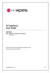
The RSGM (Remote Service Gateway Module) is a remote gateway that provides a fully
transparent connection to the iPECS host system over a broadband xDSL or Cable modem. The
remote services are implemented in the iPECS Remote Services Application Server, which is an
integral part of the iPECS software. The broadband connection employs the system’s VoIP
channels to communicate with the RSGM. The RSGM transparently extends the iPECS system
services and resources to the user’s iPECS Phone and/or Single Line Telephone interfaces over
the broadband IP network.
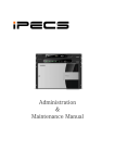
Figure 2-1 shows an example of the RSGM connection.
iPECS
Figure 2-1 RSGM Structure
3
RSGM Installer Guide
2.1
RSGM Package Contents
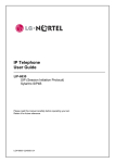
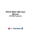
The RSGM is shipped with the iPECS RSGM module, a power adaptor and a power cord as shown
in Figure 2.1-1.
. Additionally, a ferrite core is included for EMI (Electromagnetic Interference).
Power Cord
Power Adapter
RSGM
Figure 2.1-1 RSGM package
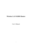
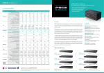
Figure 2.1-2 shows the optional components that can be used with the RSGM. These EricssonLG proprietary equipments include the iPECS Phone, the Appliance Desk/Wall mount holders and
CMU (Call Metering Unit). The iPECS Phone (LIP-24D series, LIP-7000 series) can be connected
to IP KTU port of RSGM and used as local IP phone. The DHLD (Desk Mount Holder) and the
WHLD (Wall Mount Holder) are used for mounting the RSGM. See the following Figure 2.1-2 and
Table 2.1-1.
iPECS Phone
WHLD
DHLD
Figure 2.1-2 Optional RSGM Components
The optional RSGM CMU will provide CO Line usage statistics based on Call Metering signals from
the PSTN. To obtain the RSGM with this option, contact an authorized agent of Ericsson-LG.
Table 2.1-1 RSGM & Options
No.
Product
Description
Remark
1
iPECS RSGM
Remote Service Gateway Module
Basic
2
AC/DC Adaptor –G-
AC/DC Adaptor for module, (48VDC, 0.8A)
Basic
3
AC Power Cord
AC power cord for an Adaptor
Basic
4
DHLD
Desk mount Holder for module
Option
5
WHLD
Wall mount Holder for module
Option
6
CMU
Call Metering Unit
Option
7
IPECS Phone
LIP-24D series, LIP-7000 series
Option
4
RSGM Installer Guide
2.2
Hardware Description
The RSGM can be mounted on any flat surface with the DHLD or mounted to the wall with the
WHLD. The external AC/DC adaptor feeds power to the RSGM. The connectors and indicators
on the front and rear panel are shown in Figure 2.2-1.
Figure 2.2-1 RSGM Front and Rear Panels
Connection ports
One WAN connection port (RJ-45: 10/100 Base T Ethernet port)
One PC connection port (RJ-45: 10/100 Base T Ethernet port)
One iPECS Phone connection port (RJ-45: 10/100 Base T Ethernet port, supply power to
iPECS Phone)
One Analog “CO” port (RJ-11, Loop Start)
One Analog ”SLT” port (RJ-11)
One “BGM” port (RCA Jack, RJ-11)
One Alarm/Doorbell Contact Input
Two Dry Relay Contacts
One RS-232 Serial Port
48VDC Power Input Jack
5
RSGM Installer Guide
Indicators
The following Table 2.2-1 describes the various LEDs which provide visual representation of the
RSGM activity and status.
Table 2.2-2 RSGM Activity & Status LEDs
Name
POWER
LINK/ACT
LED Color
RED
GREEN
Status
ON
Power On
OFF
No Power
ON
Valid LAN Link
OFF
Link Fail
FLASH
10/100
YELLOW
LAN POWER
RED
CO
RED
ON
SLT
RED
RED
OFF
10 MBPS
ON
Supplying power to LIP phone
OFF
Not supplying power to LIP phone
ON
CO Line in Use
OFF
CO Line Idle
IP KTU
RED
RED
CMU Installed
OFF
CMU Not Installed
ON
SLT in Use
OFF
SLT Idle
RED
S1
RED
S2
RED
SLT Ringing
ON
SLT Message Waiting Message
OFF
Message Idle
ON
IP Phone in Use
OFF
IP Phone Idle
FLASH
BGM
CO Line Ringing
ON
FLASH
MSG
TX/RX Activity
100 MBPS
FLASH
CMU
Description
IP Phone Ringing
ON
BGM Activity
OFF
BGM Idle
Future Use
ON
S1
WAN DISCONNECTED Mode
FLASH
6
RSGM WAN connected
RSGM Installer Guide
DIP Switches
The RSGM has two (2) switches on the rear panel. One is the “MODE” switch, which has four (4)
contact positions, and the other is the “LAN POWER” switch, which has a single contact position.
The “MODE” switch is used to control several options of the RSGM only when it is under WAN
DISCONNECTED mode. The function of each switch and contact position is given in Table ,
below.
Table Table -Table Switch functions
Name
MODE
LAN POWER
SWITCH
FUNCTION
ON
OFF
1
CO Dialing Type
Pulse
DTMF
2
Alarm Set
Set
Not Set
3
Relay 1 Set
Set
Not Set
4
Relay 2 Set
1
Supplying power to a LIP
Set
Not Set
Supplying power
Not supplying
Before switching “LAN POWER” ‘ON’, keep in mind that the type of terminal connected to
the port “IP KTU”. This port is intended for an iPECS Phone. If a data terminal other
than the iPECS Phone is connected, activating the “LAN POWER” switch will cause
damage to the terminal.
7
RSGM Installer Guide
2.3
Specifications
Environmental Specification
Operation Temperature
Degrees (℃)
Degrees (℉)
0 ~ 40
32 ~ 104
Optimum Operation Temperature
20 ~ 26
68 ~ 78
Storage Temperature
0 ~ 70
32 ~ 158
Relative Humidity
0~80% RH non-condensing
Power Adaptor Specification
AC Input
AC100-240V, 50/60Hz, 1A max.
DC Output
DC48V, 0.8A max
* Use only the Power adaptor is supplied with the iPECS RSGM.
Line (CO) Interface Specification
Ring Equivalence Number(REN)
0.7B
DTMF Dialing
Min. 70ms,/ Min. 70 ms
Burst time / Inter-digit time
Pulse Dialing
10 pps, 60:40% or 67:33%
Rate, Ratio
Telephony (SLT) Interface Specification
Connector
RJ-11
Loop Distance
1Km
Ring Capacity
2 US REN
Ring Frequency
25Hz
AWG #24 (0.5mm)
LAN Interface Specification
Connector
3 x RJ-45 shielded
Ethernet
10/100 BASE T
Maximum Wiring Distance
100m / 0.328Kft
Miscellaneous interface Specification
BGM
RCA jack or RJ-11
0 dBm @ 600 ohm
Dry Relay Contact
RJ-11
2A @ 30VDC
Alarm
RJ-11
TIA/EIA-232 (RS-232) Interface Specification
Connector
DB-9
Configuration/Port Settings
38400 BPS, 8 Data Bits, No parity, 1
Physical Specification
WxDxH
38.3 x 181 x 230 mm
1.5 x 7.125 x 9.05 in
Weight
0.7 Kg
1.54 lbs
W x D x H with DHLD
149 x 128 x 260 mm
5.87 x 5.04 x 10.24 in
Weight with DHLD
1.1 Kg
2.42 lbs
W x D x H with WHLD
60 x 188.3 x 280 mm
2.36 x 7.41 x 11.02 in
Weight with WHLD
1.0 Kg
2.20 lbs
8
RSGM Installer Guide
3.
3.1
INSTALLATION
Installation Procedure
The installation and configuration of the RSGM should be conducted only by an authorized agent of
Ericsson-LG. An example of the basic installation is shown in Figure 3.1-1 below.
Figure 3.1-1 RSGM Installation example
The basic procedure for installation is as follows.
1) Program the host iPECS, refer to the “iPECS Administration and Programming Manual” and
section 5.
2) Assemble the WHLD or DHLD, refer to Figure 3.2-1 WHLD/DHLD Installation, and mount
the RSGM in the holder mounting kit.
3) Connect the protective earth ( ) terminal on the rear of the RSGM to a known earth ground.
4) Connect the “WAN” port (RJ-45) on the front panel of the RSGM to the LAN port (RJ-45) of
the xDSL/Cable modem.
5) Connect the “DATA” port (RJ-45) on the front panel of the RSGM to the PC.
6) If used, connect the “IP KTU” port (RJ-45) on the front panel to the iPECS Phone. Then,
using the “LAN POWER” switch on the RSGM rear panel, activate power feed to the iPECS
Phone.
7) If used, connect the SLT port (RJ-11) on the rear panel of the RSGM to a Single Line
Telephone
8) Connect the “CO” port (RJ-11) on the rear panel of the RSGM to the CO (Central Office) line.
9) Complete the Miscellaneous connections as required.
10) Plug the AC/DC adaptor into an AC outlet and to the DC input on the front panel of the
RSGM.
11) Configure network parameters of the RSGM through the Web administration or the RS-232
Port. Refer to section 6. Network Configuration.
9
RSGM Installer Guide
3.2
WHLD/DHLD Assembly & RSGM Mounting
As depicted in Figure 3.2-1, assemble the WHLD/DHLD and mount the RSGM in the WHLD or
DHLD.
(a) RSGM installation on the WHLD
(b) RSGM installation on the DHLD
Figure 3.2-1 WHLD/DHLD Installation
To mount the RSGM on the WHLD, push the RSGM in the direction of the arrow as shown in
Figure 3.2-1(a). To remove the RSGM from the WHLD, pull the Ejector on the bottom of the front
panel.
When using of the DHLD, combine the pieces of the DHLD as shown Figure 3.2-1(b), and then
insert the RSGM from top position.
10
RSGM Installer Guide
3.3
WAN, DATA & IPKTU LAN Port Connections
The WAN, DATA and IPKTU LAN ports on the front panel require Category 5 UTP cables
terminated with RJ-45, 10/100 Base T Ethernet connections. A category 5 UTP, straight cable is
required. The three LAN ports of RSGM are wired as shown Figure 3.3-1.
Figure 3.3-1 WAN/LAN connection
The pin-out of three Ethernet jacks is as shown in Figure 3.3-2 below.
12345678
Yellow LED
On = 100Mbs
Green LED
On = Link + ACT
Flash = Activity
WAN PORT
EIA 568B (MDI)
RX+
RXTX+
TXDC+
DC-
RX+
RXTX+
TX-
TX+
TXRX+
RX-
12345678
12345678
DATA LAN Port
EIA 568A (MDIX)
IP KTU LAN Port
EIA 568A (MDIX) w/Pwr
48VDC
Figure 3.3-2 Pin Assignment of Ethernet ports
The “WAN” connector is connected to an xDSL/Cable Modem.
The “DATA LAN” port can be connected to a PC or a notebook.
The “IP KTU” port is intended for connection to an iPECS Phone. When the rear panel “LAN
POWER” switch is ‘ON’, the RSGM delivers 48Vdc power to the phone through unused pairs (pin
4-5 and 7-8). If a PC or other data device is connected to this port, be sure LAN POWER switch is
in the ‘OFF’ position. See Figure 3.3-1 above. In order to reduce EMI, the LAN cable connected
11
RSGM Installer Guide
to “IP KTU” port is required to be turned by the ferrite core packaged in a box.
3.4
The “IP KTU” port of the RSGM does not support the IEEE 802.3af Standard.
If you do not use an iPECS Phone, the “IP KTU” port can be used for other LAN
equipment. In this case, be sure that “LAN POWER” switch is in the ‘OFF’ position;
otherwise, the LAN equipment connected to “IP KTU” port will be damaged.
“CO” and “SLT” Port Connections
The “CO” port on the rear panel is connected to the CO Line from the Public Exchange. The “SLT”
port allows a telephone or FAX machine to be connected. The subscriber loop lengths of the
“SLT” port can be extended up to 1 Km.
CO line
Telephone
Power
Earth
Figure 3.4-1 CO and SLT connection
As shown in Figure 3.4-2, the RJ-11 jack of the “CO” and “SLT” ports connects Tip and Ring for the
telephony interface.
1
2
3
4
TIP
1
2
3
4
RING
CO(RJ-11)
TIP
RING
SLT(RJ-11)
Figure 3.4-2 Pin Assignment of CO and SLT ports
12
RSGM Installer Guide
3.5
Miscellaneous Connections
3.5.1
TIA/EIA-323 (RS-232) Connection
The DB-9 connector located on the front panel of the RSGM is used for TIA/EIA-323(RS-232)
connection. This connector is employed to provide terminal access to the network configuration or
system diagnostics of the RSGM. The serial configuration of the RSGM is 38400bps, 8 bits, no
parity, and one stop bit.
This TIA/EIA-323 (RS-232) does not support hardware flow control signals.
needed (TD, RD, and SG). See Figure 3.5-1.
6
7
8
9
1
2
3
4
5
TD
RD
6
RD
TD
7
8
9
SG
SG
1
2
3
4
6
7
8
9
5
1
2
3
4
5
TD
TD
RD
14
Only three wires are
1
2
3
RD
SG
SG
7
25 13
RSGM
DB-9 RS-232
Terminations
Typical Terminal
DB-9 RS-232
Terminations
RSGM
DB-9 RS-232
Terminations
Typical Terminal
DB-25 RS-232
Terminations
Figure 3.5-1 Pin Assignments of TIA/EIA-323
Table 3.5-1 Pin Description of TIA/EIA-323
Designation
Function
TD
Transmitted Data
RD
Received Data
SG
Signal Ground
3.5.2
External BGM
The BGM jack is used to connect to an external music source. To use the external music, connect
a music source to the BGM RCA jack on the front panel using an audio cable or with an RJ-11 plug
on the rear panel BGM RJ-11 jack. See Figure 2.2-1 and Figure 3.5-2.
The “BGM” connection on the rear panel is common with BGM RCA jack of the front panel.
3.5.3
Alarm Port
The RSGM has an alarm port. The Alarm port is used for sensing the status of the external switch,
e.g. alarm or door bell. See Figure 3.5-2.
13
RSGM Installer Guide
3.5.4
External Relay1, 2
The RSGM has two dry relay contacts with 2A @30VDC. See Figure 3.5-2. These contacts are
used to control an external device such as a door-lock release mechanism.
RELAY2
ALARM
1
2
3
4
RELAY1
BGM
1
2
3
4
ALARM
Relay
Contact2
Relay
Contact1
Music
Source
Figure 3.5-2 Pin Assignments of BGM/ALARM/Relay Contacts
3.5.5
AC/DC Power Adaptor Connection
An AC/DC adaptor is packaged with the RSGM. The adaptor is supplied with a two (2) meter (six
(6) foot) AC cord terminated with the nationally relevant AC blade type. The adaptor supports AC
input power systems with rated voltage range of 100-240 VAC @ 50/60 Hz. The adaptor provides
48 VDC, 0.8 amps. The DC output connector is cabled to the adaptor with a two (2) meter (six (6)
foot) cable. Figure 3.5-3 shows the AC/DC Adaptor for the RSGM.
Assure the AC Power connection is within the rated voltage, frequency and current ratings
of the AC/DC adaptor.
Figure 3.5-3 Power Adaptor
Connect the AC power cord to the Adaptor and plug-in to the AC power source. Plug the DC
output connector into the corresponding connector on the lower rear panel of the RSGM. Upon
connection of the AC/DC Adaptor, the RSGM will power-up. When power is applied, the RSGM
will provide power to the “IPKTU LAN” port, if the “LAN POWER” switch is ‘ON’, and the RSGM will
attempt to register with the remote host iPECS.
14
RSGM Installer Guide
3.5.6
RSGM Power-Up
To properly register, the “WAN” port must be connected to an operational broadband connection
and the RSGM must be properly programmed with the public IP address of the iPECS, refer to
section 6. In addition, for successful registration, the iPECS must be programmed with the
Ethernet MAC address of the RSGM, refer to section 5.
During the initial power-up, since the RSGM programming has not been accomplished, the RSGM
will enter the “WAN DISCONNECTED” mode. The “WAN DISCONNECTED” mode will occur
should any of the following conditions exist:
1) RSGM not assigned with proper host iPECS IP address,
2) RSGM Network configuration improper,
3) “WAN” connection improper or physically disconnected,
4) Host iPECS not assigned with RSGM MAC address,
5) ISP connection not operational, or
6) Host iPECS not operational.
In the “WAN DISCONNECTED” mode, communication between the RSGM and the host is not
possible and thus the RSGM and the iPECS Phone or SLT will not have access to services and
resources of the iPECS. The ‘S2’ LED on the front panel of the RSGM will light steadily and, if an
iPECS Phone is connected to the RSGM, the LCD will display the “WAN DISCONNECTED”
message. The iPECS Phone will be capable of placing/receiving a call from the locally connected
CO Line. In addition, the telephone connected to the “SLT” port is directly connected to “CO” port
by the internal PFT (Power Fail Transfer) relay, refer to section 4.
15
RSGM Installer Guide
4. Power Fail Transfer
Should power to the RSGM fail, the external SLT port is directly connected to the CO port through
the internal Power Fail Transfer relay. In this case, only the telephone connected to “SLT” port can
place/receive a call through locally connected CO facility. If an iPECS Phone is connected to the
RSGM, the loss of power to the RSGM also removes power to the iPECS Phone and thus it is nonoperational. Normal operation of the RSGM and iPECS Phone return upon return of power to the
RSGM.
16
RSGM Installer Guide
5.
iPECS Admin Programming for RSGM
In this section, several host system Admin Programs specific to the RSGM are introduced. For
detailed information about the iPECS Admin Programming, please refer to “iPECS Administration
and Programming Manual”.
The RSGM provides a number of local services in addition to transparent access to the host iPECS.
These include BGM/MOH, Alarm/Doorbell monitor and External Control contacts. PGM code
group 430-435 allow for configuration of the RSGM identification and attributes for each RSGM
supported by the host iPECS system.
5.1
RSGM Address & Configuration -PGM Code 430
The RSGM’s MAC Address and other device specific configurations must be input to the iPECS
prior to registration. In addition, the IP address and other device specific configuration can be
displayed after registration.
5.2
RSGM Multi-Cast RTP/RTCP Ports -PGM Code 431
The iPECS does not provide BGM/MOH to RSGM. The RSGM employs local BGM and MOH
facilities, to reduce traffic load on the WAN and VoIP channel processors. The RSGM uses IP
Multicast for local BGM and MOH transport. There are two music sources available with the
RSGM, an internal tone music source and an external source may be connected. Separate UDP
port numbers are required for RTP and RTCP packets for each source. The default port numbers
are programmable so they can be changed if needed.
5.3
RSGM External Control Contact -PGM Code 432
The RSGM incorporates a relay contact, which can be employed to control an external device.
The contact is assigned to activate under one of several conditions. As a Loud Bell Contact (LBC),
the contact will be activated when the RSGM station receives an external call. Alternatively, the
contact may be used as a Door Lock Release contact, which is activated when the Door Unlock
code is dialed by the RSGM station.
5.4
RSGM Alarm Attribute -PGM Code 433
The RSGM incorporates circuitry to monitor an external contact. This contact is generally
employed as an Alarm indicator or Doorbell. The Alarm attributes define the operation of the
monitoring circuitry. For the Alarm, the signal to the RSGM stations can be repeated or a single
burst. The former is often desired. For the Doorbell, a single tone is sent each time the contact
activates.
5.5
RSGM Music Assignment -PGM Code 434
The RSGM provides Background Music (BGM) to the local iPECS Phone. It also provides MOH
to the local CO Line when placed on hold. BGM is provided from the assigned Music source,
which may be an internal or external source. MOH may use the assigned Music source or an
internal “Hold Tone”.
17
RSGM Installer Guide
5.6
RSGM Service Attributes -PGM Code 435
The RSGM exchanges voice (RTP) packets with iPECS and other users employing VoIP channels
of the iPECS for RTP packet relay, implementing security (IPSec) and for QoS. The VoIP
channels are assigned to a CO/IP line group in the iPECS database and must be assigned for use
by the RSGM. Packets can be tagged with a DiffServ Code Point to provide per-hop priority.
Also, the user can access the RSGM CO Line or a CO Line from the system’s 1st CO Line group by
dialing the CO Line access code (‘9’) Refer to the “iPECS Administration and Programming
Manual” for details of RSGM Service Attributes.
18
RSGM Installer Guide
6.
Network Configuration
iPECS local devices need not be configured because the iPECS controls them directly. However,
for remote devices such as the RSGM, configuration of the device by installer is required for proper
data communication over the Internet. This is accomplished using a Web browser via the LAN
connection or by a terminal emulator (e.g. Hyper Terminal) via the RS-232C serial connection.
Web configuration is easier to use, but serial configuration may be useful for the first-time
configuration.
Network configuration consists of RSGM WAN, LAN, and System configurations. These are
explained in the following three sections of General, Web Configuration, and Serial Configuration.
The last two sub-sections of this section describe typical network configuration examples and the
detailed explanation of network parameters.
6.1
General
The RSGM has three network interfaces. One is the WAN interface that is connected to the
Internet side, and the others are LAN interfaces used to connect a local PC and iPECS Phone.
6.1.1
WAN Port Related Settings
In order to send/receive data packets through the Internet, the RSGM’s WAN side IP address,
subnet mask, and gateway (router) address must be configured properly. The address information
can be set manually (static) or automatically using DHCP (Dynamic Host Configuration Protocol).
The RSGM supports connections to an xDSL/Cable modem as well as Ethernet switch (Hub).
19
RSGM Installer Guide
6.1.2
LAN Port Related Settings
The RSGM LAN ports can be used to connect a local PC and iPECS Phone. No configuration of
the iPECS Phone is required as it is configured automatically in ‘Plug-and-Play’ mode as with other
iPECS local devices.
For PC LAN port, the RSGM provides a DHCP server, thus the PC’s network setting must be
changed to Dynamic Address Assignment mode. This setting can be changed by using the
“Control Panel” of MS-Windows. For example, after opening “Local Area Connection Properties”
Figure 6.1-1, select “Internet Protocol (TCP/IP)” and click “Properties” button.
Figure 6.1-1 Local Area Connection Properties
20
RSGM Installer Guide
This will display the “Internet Protocol (TCP/IP) Properties” window. If the PC has already been
set to use DHCP as shown in Figure 6.1-2 below, the settings need not be changed.
Figure 6.1-2 DHCP Setting
However, if the PC is set to use a ‘fixed IP address’ as shown in 6.2-3 below, the settings must be
changed to “Obtain an IP address automatically” as shown in Figure 6.1-2 above.
Figure 6.1-3 Fixed Address Setting
21
RSGM Installer Guide
6.2
RSGM Configuration via Web Browser
Web Configuration is an easy way to configure the RSGM network parameters using a Web
browser. A Web browser is an easy method for access the RSGM Web Admin pages and may be
employed over LAN or WAN connections. The LAN Connection method is intended for first time
configuration while the WAN connection method is intended for remote access after the RSGM has
successfully registered with the host iPECS.
6.2.1
General Information
After changing PC’s network settings to Dynamic Address Assignment mode, the RSGM Web
Admin can be accessed with a Web browser by “pointing” to the RSGM LAN side default address,
“10.10.50.50”. This will return the RSGM Admin Home page see Figure 6.2-1. On the left side of
the window is the Admin Menu screen and in the center is the Admin main screen. The RSGM
Admin Home page displays general information on the RSGM settings.
Figure 6.2-1 Web Admin Home
22
RSGM Installer Guide
6.2.2
WAN Configuration
When “WAN” on the left menu or “WAN Status” on the top menu is selected, the WAN Status page
appears. This page shows the WAN port network parameters and status.
Figure 6.2-2 WAN Status
Selecting “WAN Settings” on the top menu bar of the main screen returns the WAN Settings page.
If changes are made, select the “Save WAN Settings” button to store the changes.
Figure 6.2-3 WAN Setting
23
RSGM Installer Guide
If dynamic address assignment is to be used, just click “Obtain WAN configuration dynamically”
radio button. Other information need not be entered in this case. This mode can be utilized
when DHCP server exists in the same network segment of the RSGM. In addition, if connected to
xDSL/Cable modem and a fixed address is not assigned, this mode should be selected.
If fixed IP address is to be used, click “Specify fixed WAN configuration” radio button, and then
enter the IP Address, IP Net mask and IP Gateway information. Other information is optional and
need not be entered.
Selecting PPPoE from the top menu bar returns the PPPoE page Figure 6.2-4, which is for used
configuring PPPoE parameters when “User Name” and “Password” are required to log in to the
ISP’s service. If changes are made, select the “Save PPPoE Settings” button to store the
changes.
Figure 6.2-4 WAN PPPoE Configuration
If the ISP does not require entry of a “User Name and “password to log in, the “Enable PPPoE”
combo box should be set to “No”.
If the ISP requires entry of User Name and Password, set “Enable PPPoE” combo box to “Yes”,
and enter the appropriate “User name” and “Password”. “Service Name” and “AC Name”
(Account Name) are optional entries, enter these values only if provided by the ISP and they
required for proper modem operation.
Note, when PPPoE is used, the IP address is generally assigned by ISP thus, “Obtain WAN
configurations dynamically” should be selected in previous “WAN Settings” page.
24
RSGM Installer Guide
Selecting VLAN from the top menu bar returns the VLAN settings page Figure 6.2-5. If changes
are made, select the “Save VLAN Settings” button to store the changes.
Figure 6.2-5 VLAN/Priority Configuration
VLAN packets are not compatible with normal Ethernet packets, and these settings should be
configured only if the RSGM local network is using VLAN/Priority. If VLAN tags are enter by
mistake, they can be corrected only by using Serial Configuration.
25
RSGM Installer Guide
Selecting DiffServ from the top menu bar returns the DiffServ settings page Figure 6.2-6.
changes are made, select the “Save DiffServ Settings” button to store the changes.
If
Figure 6.2-6 DiffServ Configuration
ISPs that support DiffServ (Differentiated Services) may require end-devices to preset the DiffServ
Code Point (DSCP) to give priority to specific types of packets. In this case, the DiffServ value
can be assigned on this page. When setting the value, click “Enabled” radio button on “Enable
DiffServ” item, then select or enter the assigned value.
26
RSGM Installer Guide
6.2.3
LAN Configuration
When “LAN” on the left menu or “LAN Settings” on the top menu is clicked, LAN Settings page will
display. This page shows LAN side network parameters. If changes are made, select the “Save
LAN Settings” button to store the changes.
Figure 6.2-7 LAN Settings
The IP address and subnet mask of LAN side interface can be changed on this page by entering
new values and clicking “Save LAN Settings” button.
27
RSGM Installer Guide
Selecting DHCP from the top menu bar returns the DHCP Server Configuration page Figure 6.2-7.
If changes are made, select the “Save DHCP Settings” button to store the changes. To view the
DHCP assignment table, select the “View DHCP Table”.
Figure 6.2-8 DHCP Server Configuration
By using this page, DHCP can be enabled or disabled by clicking either “Enabled” or “Disabled”
radio button on “Server Settings” item, and client IP address range can also be changed. In
addition, the DNS server for the local client can be configured, and it is possible to assign specific
IP addresses statically to designated clients.
Detailed description of other configuration parameters available under the LAN page are discussed
in the last section of this chapter.
28
RSGM Installer Guide
6.2.4
System Configuration
When “System” on the left menu or “System Settings” on the top menu is clicked, System Settings
page will display. This page shows the IP address of the host iPECS system. If changes are
made, select the “Save LAN Settings” button to store the changes. In order for the RSGM to
register with the host iPECS, the IP address of the iPECS must be set. The iPECS administrator
should have the host system IP address.
Figure 6.2-9 System Configuration
Detailed description of the other configuration parameters available under the System page are
discussed in the last section of this chapter.
29
RSGM Installer Guide
6.3
RSGM Configuration via Serial Terminal
Serial Terminal configuration is a simple way to configure the RSGM network parameters using
Terminal Emulator software (e.g. Hyper Terminal) via TIA/EIA-323 serial connection. It provides
access to the RSGM Terminal Admin pages that are similar in function to the Web Admin pages.
Serial Terminal Admin is suitable for first-time installation.
The serial communication settings for terminal emulators are as follows;
Bits per Second (bps) : 38400
Data Bit : 8
Parity : None
Stop Bit : 1
Flow Control : None
As the Serial Terminal configuration is conceptually the same as Web configuration, this section will
concentrate on how use Serial Configuration to change network parameters. Please refer to the
previous section, RSGM Configuration via Web browser.
Figure 6.3-1 Initial Serial Terminal Screen
After connecting the PC and RSGM with TIA/EIA-323 serial cable, launch the terminal emulator
(e.g. Hyper Terminal), and then press “Enter” key, you will see the menu above.
The Serial Terminal configuration employs a directory structure. To enter the WAN Configuration
sub-directory, type “wan” and then press “Enter” key, the WAN Configuration menu as in Figure 6.32 will be displayed. Here there are sub-directories and/or operation commands. To return to
higher level directory, type “..” and then press “Enter” key.
30
RSGM Installer Guide
Figure 6.3-2 Entering WAN Configuration
The “wan” directory has three sub-directories. “wanset” sub-directory, which contains address
settings related operation commands, “pppoe” sub-directory, which contains PPPoE related
settings that may be needed when using xDSL/Cable modem and “wanvaln” sub-directory, which
contains WAN side VLAN related operation commands.
Figure 6.3-3 WAN Settings Menu
By typing “wanset” in “wan” sub-directory, you will see the menu shown in Figure 6.3-3. Note, the
“mode” command on third line works as a toggle; each time “mode” is typed, the right side Mode
string will be toggled between “FIXED” and “DYNAMIC”.
31
RSGM Installer Guide
Figure 6.3-4 Setting WAN DHCP Mode
If the RSGM “WAN” port will operate in DHCP mode, setting the Mode to “DYNAMIC” will be the
only required setting in the “wanset” sub-directory. However, to use fixed addressing, set the
Mode to “FIXED” and the addressing data must be configured manually as described in the
following paragraphs.
Figure 6.3-5 Displaying WAN Address Information
At first, by typing “get all” and pressing “Enter” key, you may check current address settings. IP
Address, Subnet Mask, and Gateway Address are mandatory parameters required for Fixed (static)
IP addressing.
32
RSGM Installer Guide
Figure 6.3-6 Setting WAN IP Address
As an example, by typing “set ip 165.243.50.65”, you can change the RSGM “WAN” port IP
address. Other address information can be changed in a similar manner. For example, in order
to change the gateway address to “165.243.50.254”, you type “set gateway 165.243.50.254” and
press “Enter” key.
Figure 6.3-7 Displaying WAN Address Information
If you type “get all” again, you will see “165.243.50.65” inside the braces. This means that the
“WAN” port address will be changed to this address after restarting RSGM.
33
RSGM Installer Guide
Figure 6.3-8 Entering System Configuration
To return to the root directory, type, “/” and then press “Enter” key.
directory, you can enter the System Configuration sub-directory.
Then, by typing “system” in root
Figure 6.3-9 Displaying System Information
Again, you may check current System Configuration settings by typing “get all” in “system” directory.
Here, you may also check RSGM S/W version and revision date information.
34
RSGM Installer Guide
Figure 6.3-10 Setting System IP Address
By typing “set mfim xxx.xxx.xx.xxx”, you can change the IP address of host iPECS (e.g. MFIM/E)
and after restarting the RSGM, the new IP address entered will be used.
Detailed description of configuration parameters will be shown in the last section of this chapter.
35
RSGM Installer Guide
Typical Network Configuration Examples
6.4
Even though there are many parameters that can be configured, only a few parameters need to be
configured for the first-time configuration. There can be some variations in configuring RSGM, but
the main procedure is simple.
1) Change the PC’s network settings to Dynamic Address Assignment mode. If a PC is will
not be connected to the RSGM Data (PC) port, skip this step.
2) By Web browser or Serial Terminal, configure WAN side addresses in WAN Configuration.
3) Configure IP address of the host iPECS (e.g. MFIM/E) in System Configuration.
Remember the RSGM “LAN” port default IP address is 10.10.50.50, so you may access the RSGM
Web Admin pages from local PC with this IP address.
6.4.1
1)
2)
3)
6.4.2
1)
2)
3)
Normal LAN Environment with Fixed IP Address
WAN Settings
Set Address Configuration mode to “FIXED”
Enter fixed address information (IP address, Subnet Mask, Gateway address)
PPPoE Settings
Set PPPoE mode to Inactive (No)
System Settings
Set IP address of the host iPECS (e.g. MFIM)
Normal LAN Environment with DHCP Server
WAN Setting
Set Address Configuration mode to “DYNAMIC”
PPPoE Settings
Set PPPoE mode to Inactive (No)
System Settings
Set IP address of the host iPECS (e.g. MFIM)
6.4.3
1)
xDSL/Cable Modem with User Name and Password Required
WAN Settings
Set Address Configuration mode to “DYNAMIC”
2) PPPoE Settings
Set PPPoE mode to Active (Yes)
Enter User name and Password (Mandatory). Enter Service name and AC name if
needed/available (Optional).
3) System Settings
Set IP address of the host iPECS (e.g. MFIM)
6.4.4
1)
2)
3)
xDSL/Cable Modem without User Name and Password
WAN Settings
Set Address Configuration mode to “DYNAMIC”
PPPoE Settings
Set PPPoE mode to Inactive (No)
System Settings
Set IP address of the host iPECS (e.g. MFIM)
36
RSGM Installer Guide
6.5
Network Configuration Descriptions
6.5.1
WAN Configuration
The WAN connection is used for the communication with the iPECS as well as other network
devices beyond the local network.
WAN Settings
These settings allow configuration of the Ethernet WAN interface. First, select whether you wish
the WAN interface to be configured for dynamic (via a DHCP server on the network if Ethernet, or
via PPP if using PPPoE), or static IP addressing. If you wish to assign the WAN interface settings
statically, enter the IP address, subnet mask, default gateway IP address and DNS server IP
address. It is also recommended that the network domain name be provided as well, to ensure
correct DNS operation.
PPPoE Settings
First, select whether PPPoE is enabled or disabled. If enabled, enter the username and password
required for the login (authentication) process. If the PPPoE server (service provider) requires any
special Service Name or AC (Account) Name to be set, you can specify the tags here.
VLAN Settings
VLAN settings allow configuration of VLAN tag and/or Priority tag for all outgoing packets.
37
RSGM Installer Guide
6.5.2
LAN Configuration
The LAN connections are used for communicating with an IP KTU and/or a PC connected to the
LAN ports of RSGM.
LAN Settings
Assign an IP address to the LAN Ethernet port. This IP address is also the default router address
for the devices on the private (local) LAN. The default LAN interface IP address is set to
10.10.50.50. Enter the subnet mask for the private LAN. If you wish to set the broadcast and
multicast limits, enter these values as percentages of the LAN interface Ethernet bit rate. Leaving
these values blank will imply values of 100%.
DHCP Settings
DHCP settings allow configuration of the private LAN DHCP server. Specify whether the device’s
internal DHCP server feature is enabled or disabled. Also, indicate the IP address range to use
for DHCP assignments to the LAN. Specify the domain name (optional) that is provided to LAN
clients via DHCP. Two optional static DNS server IP addresses can be entered that will be
provided to LAN clients via DHCP. These are in addition to the DNS servers automatically
provided by WAN connections.
Via the Web configuration, up to eight static DHCP addresses can be configured. User can add or
remove static assignment entries, and view the current active DHCP client-binding table. The
device’s internal DHCP client binding table cleared, but be aware that doing this will destroy the
DHCP server’s knowledge of the LAN clients it has provisioned, and may result in client problems
when a client tries to renew its lease.
Port Forwarding Settings
Port Forwarding allows configuration of the device’s port forwarding feature. Port forwarding
provides WAN access to the internal LAN, by specifying that traffic over certain ports are to be
directed at particular LAN hosts. Up to eight port forwarding entries ("Pinholes") can be configured.
To add a port forwarding entry configure the Port Range to be forwarded, the Protocol to be forward
(TCP, UDP or both), and destination LAN IP Address to be used. User may also remove specific
entries. Note that certain port numbers may be reserved by the CPE for its own internal use.
These ports may not be used for port forwarding to the LAN. Ports which may be reserved by the
CPE include those used by iPECS signaling, RTP packets, HTTP, etc. All reserved (unavailable)
ports will be displayed on this page.
Router Settings
Router settings allow configuration of the device’s core router functionality. If you wish for the
router to update its routing tables dynamically, specify whether RIPv2 dynamic routing information
is to be received or transmitted (or both). In addition, up to eight static route entries can be
assigned via Web configuration. To add a static route, enter the static route Destination IP
address, subnet Mask, gateway IP Address, metric, and interface. Metric is a number from 1 to 15
inclusive. Users may also remove specific entries or view current internal routing table.
VLAN Settings
VLAN settings allow configuration of VLAN tag and/or Priority tag for all outgoing packets.
38
RSGM Installer Guide
6.5.3
System Configuration
System configuration contains the items that do not specifically belong to WAN or LAN categories.
System Settings
System settings allow configuration of iPECS IP address (e.g. MFIM/E) so that RSGM can register
with iPECS.
Service Access Settings
Service access allows access to certain system level network services on the device's interfaces to
be enabled/disabled. Specifically, HTTP access from devices on the LAN or WAN or both can be
allowed or denied.
VLAN Settings
VLAN settings allows configuration of the VLAN settings for RTP packets. Specific VLAN settings
for RTP packets are separately applied, which will override the general values set in WAN or LAN
settings. If no special RTP VLAN settings are applied, then RTP packets will also use the general
VLAN settings entered in WAN or LAN settings.
39
RSGM Installer Guide
7.
Troubleshooting Guide
Table 7-1 Troubleshooting Guide
Problem
Reason
LED of LAN jack is not
operated
LAN cable connection is physically
failed
LAN POWER switch is off
1) Physically, WAN connection failed
2) The RSGM is not registered in the
iPECS System
3) The network configuration of the
RSGM has some problem.
4) An ISP has some problem
iPECS Phone power is off
WAN DISCONNECTED
mode
Solution
Check cable connection.
Switch “LAN POWER” on.
1) Check LAN cable, and re-connect,
2) Register the RSGM in the host iPECS,
3) Check the RSGM network configuration,
4) Ask the ISP.
Contact the agent of Ericsson-LG.
On the PC behind RSGM,
network
application
(e.g Web Browser)
does not work properly
PC is not assigned IP address properly
from RSGM DHCP server after
restarting RSGM. Some PC (OS)
may not detect the DHCP server
restart.
Restart network adaptor by using “ipconfig
/renew_all” (Win95/98) command or
“ipconfig
/renew”
(Win2000/XP)
command on Command Prompt, or
restart the network adaptor in other
available way. For Win95/98, the PC
may have to be restarted.
RSGM seems to stop
packet communication
after setting VLAN/
Priority
End user’s local network environment
may not be configured or does not
support VLAN/ Priority.
By using Serial Configuration, disable VALN/
Priority settings.
Packet
communication
does not seem to work
properly with xDSL/
Cable modem.
1). WAN side address settings and
PPPoE settings are not correct.
2). Other network devices (e.g. PC) are
connected together with RSGM to
the same xDSL/ Cable modem even
though only single IP address was
assigned from ISP.
1). Check WAN side address settings
together with PPPoE settings. (Refer to
Chapter 6 for details)
2). Disconnect all other network devices
from the modem, and restart RSGM.
WAN and LAN side network address
must be different because RSGM is
a layer 3 (IP level) routing device.
If LAN side IP address is 10.10.50.50, WAN
side IP address should be other than
10.10.50.X (e.g. 123.123.10.10).
If
RSGM must use 10.10.50.X for WAN
side, LAN side address should be
changed.
Packet routing between
WAN and LAN ports
does not work properly.
40