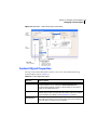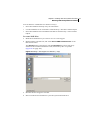
1
PersonalEffect® uCreate Print User Guide TM Version 6.2 Notices © 2013 XMPie®, A Xerox Company. All rights reserved. U.S. Patents 6948115, 7406194, 7548338, 7757169 and pending patents. JP Patent 4406364B and pending patents. uCreateTM Print Version 6.2 User Guide, Document Revision: 1.33, February 2013 For information, contact XMPie Inc. 485 Lexington Avenue 10th. Floor New York, NY 10017 More information can be found at www.xmpie.com XMPie provides this publication "as is" without warranty of any kind, either express or implied. This publication may contain technical inaccuracies or typographical errors. While every precaution has been taken in the preparation of this document, the publisher and author assume no responsibility for errors or omissions. Nor is any liability assumed for damages resulting from the use of the information contained herein. Changes are periodically made to the information herein; these changes will be incorporated in new editions of the publication. XMPie may make improvements and/or changes in the product(s) and/or the program(s) described in this publication at any time. XMPie, the XMPIE logo, PersonalEffect, uChart, uCreate, uDirect, uEdit, uImage, uPlan, uProduce, uStore, StoreFlow, Circle, ADOR, XLIM, RURL, Hosted e-Media Express Edition, and the slogan "one to one in one" are trademarks or registered trademarks of XMPie, A Xerox Company, and may not be used without permission. No part of these materials may be used or reproduced in any form, or by any means, without the express written consent of XMPie. To request permission to use these materials, please contact [email protected]. XEROX® and XEROX FreeFlow®, FreeFlow Output Manager® and FreeFlow Process Manager® are trademarks of Xerox Corporation in the United States and/or other countries. Adobe Acrobat, Adobe Dreamweaver, Adobe Illustrator, Adobe InDesign, Adobe Photoshop and Adobe After Effects are trademarks of Adobe Systems Incorporated. SQL Server 2008, SQL Server 2008 R2, Windows Server 2008, Windows XP, Windows Vista, Windows 7, Microsoft Office, Microsoft Excel and Microsoft Access are trademarks or registered trademarks of Microsoft Corporation. Mac OS is a trademark of Apple Computer, Inc. ComponentArt is a trademark of ComponentArt Inc. Other trademarks and service marks are the property of their respective owners. Contents Contents Chapter 1: Introduction to PersonalEffect . . . . . . . . . . . . . . . . . . . . . 1 The PersonalEffect Solution - Overview. . . . . . . . . . . . . . . . . . . . . . . . . . . . . . . . . . . . . . . . . . . . . . 1 Dynamic Documents. . . . . . . . . . . . . . . . . . . . . . . . . . . . . . . . . . . . . . . . . . . . . . . . . . . . . . . . 2 Campaigns . . . . . . . . . . . . . . . . . . . . . . . . . . . . . . . . . . . . . . . . . . . . . . . . . . . . . . . . . . . . . . 3 How Does PersonalEffect Work? . . . . . . . . . . . . . . . . . . . . . . . . . . . . . . . . . . . . . . . . . . . . . . . 4 PersonalEffect Core Applications . . . . . . . . . . . . . . . . . . . . . . . . . . . . . . . . . . . . . . . . . . . . . . . . . . 5 uPlan . . . . . . . . . . . . . . . . . . . . . . . . . . . . . . . . . . . . . . . . . . . . . . . . . . . . . . . . . . . . . . . . . . 6 uCreate Print . . . . . . . . . . . . . . . . . . . . . . . . . . . . . . . . . . . . . . . . . . . . . . . . . . . . . . . . . . . . . 7 uProduce. . . . . . . . . . . . . . . . . . . . . . . . . . . . . . . . . . . . . . . . . . . . . . . . . . . . . . . . . . . . . . . . 7 PersonalEffect Architecture . . . . . . . . . . . . . . . . . . . . . . . . . . . . . . . . . . . . . . . . . . . . . . . . . . . . . . 9 Chapter 2: Introduction to uCreate . . . . . . . . . . . . . . . . . . . . . . . . . . 11 Activating your uCreate License Key . . . . . . . . . . . . . . . . . . . . . . . . . . . . . . . . . . . . . . . . . . . . . . . 13 Activating an Additional License Key . . . . . . . . . . . . . . . . . . . . . . . . . . . . . . . . . . . . . . . . . . . 13 Deactivating your License Key . . . . . . . . . . . . . . . . . . . . . . . . . . . . . . . . . . . . . . . . . . . . . . . . . . . 14 Basic Workflow. . . . . . . . . . . . . . . . . . . . . . . . . . . . . . . . . . . . . . . . . . . . . . . . . . . . . . . . . . . . . . 15 Workflow for Print and Cross-Media Campaigns. . . . . . . . . . . . . . . . . . . . . . . . . . . . . . . . . . . . 15 Workflow for Print & Web Campaigns for Hosted e-Media . . . . . . . . . . . . . . . . . . . . . . . . . . . . 16 Exporting your Print Campaign to Create a New Web Campaign using a Port. . . . . . . . . . . . 17 Linking your uCreate Campaign to an Existing ICP Port . . . . . . . . . . . . . . . . . . . . . . . . . . . 18 Chapter 3: Getting Started with uCreate Print . . . . . . . . . . . . . . . . . 19 uCreate Print Panel . . . . . . . . . . . . . . . . . . . . . . . . . . . . . . . . . . . . . . . . . . . . . . . . . . . . . . . . . . . 20 Content Object Data Column . . . . . . . . . . . . . . . . . . . . . . . . . . . . . . . . . . . . . . . . . . . . . . . . . 23 Content Object Types . . . . . . . . . . . . . . . . . . . . . . . . . . . . . . . . . . . . . . . . . . . . . . . . . . . . . . 25 uCreate Print Panel Options menu . . . . . . . . . . . . . . . . . . . . . . . . . . . . . . . . . . . . . . . . . . . . . . . . 28 Linking a Document to your Campaign Data . . . . . . . . . . . . . . . . . . . . . . . . . . . . . . . . . . . . . . . . . 34 iii Contents Linking a Document to a Data Source . . . . . . . . . . . . . . . . . . . . . . . . . . . . . . . . . . . . . . . . . . 35 Supported Data Sources . . . . . . . . . . . . . . . . . . . . . . . . . . . . . . . . . . . . . . . . . . . . . . . . . 35 Database Fields Usage: Available Fields and Primary Field . . . . . . . . . . . . . . . . . . . . . . . . . . . . 37 Choosing the Available Data Source Fields . . . . . . . . . . . . . . . . . . . . . . . . . . . . . . . . . . . . 37 Setting the Primary Field . . . . . . . . . . . . . . . . . . . . . . . . . . . . . . . . . . . . . . . . . . . . . . . . 38 Linking a Document to Counter Data Sources . . . . . . . . . . . . . . . . . . . . . . . . . . . . . . . . . . . . . 38 Content Object List Context Menu . . . . . . . . . . . . . . . . . . . . . . . . . . . . . . . . . . . . . . . . . . . . . 39 Dual-Mode: Linking to a Data Source or Linking to a Plan . . . . . . . . . . . . . . . . . . . . . . . . . . . . 40 Switching Modes . . . . . . . . . . . . . . . . . . . . . . . . . . . . . . . . . . . . . . . . . . . . . . . . . . . . . . 41 Linking a Document to a Plan (not available for uCreate Print Standard) . . . . . . . . . . . . . . . . . . 41 Editing a Plan . . . . . . . . . . . . . . . . . . . . . . . . . . . . . . . . . . . . . . . . . . . . . . . . . . . . . . . . 42 Reloading a Plan . . . . . . . . . . . . . . . . . . . . . . . . . . . . . . . . . . . . . . . . . . . . . . . . . . . . . . 42 Converting Content Object Rules to a Plan File . . . . . . . . . . . . . . . . . . . . . . . . . . . . . . . . . 43 Linking a Document to a Proof Set . . . . . . . . . . . . . . . . . . . . . . . . . . . . . . . . . . . . . . . . . 44 Linking a Document to an ICP Port (not available for uCreate Print Standard) . . . . . . . . . . . . . . 45 Re-linking a Document to an Updated or Different Data Source . . . . . . . . . . . . . . . . . . . . . . . . 49 Matching the Previous and Current Data Sources . . . . . . . . . . . . . . . . . . . . . . . . . . . . . . . 49 Relinking a Document to an ICP Port (not available for uCreate Print Standard) . . . . . . . . . . . . . 57 Tagging Design Objects with Content Objects . . . . . . . . . . . . . . . . . . . . . . . . . . . . . . . . . . . . . . . . 58 Tagging a Design Object with a Text Content Object . . . . . . . . . . . . . . . . . . . . . . . . . . . . . . . . 58 Tagging a Design Object with a Graphic Content Object . . . . . . . . . . . . . . . . . . . . . . . . . . . . . 59 Tagging a Design Object with a Text File Content Object . . . . . . . . . . . . . . . . . . . . . . . . . . . . . 59 Tagging a Design Object with an Automatic Web Content Object . . . . . . . . . . . . . . . . . . . . . . . 60 Using Nested Composition. . . . . . . . . . . . . . . . . . . . . . . . . . . . . . . . . . . . . . . . . . . . . . . . . . . 61 Tagging an Asset File with Content Object Reference . . . . . . . . . . . . . . . . . . . . . . . . . . . . 61 Setting up Nested Composition with a Plain Text Asset . . . . . . . . . . . . . . . . . . . . . . . . . . . 62 Using Nested Composition with Adobe Tagged Text . . . . . . . . . . . . . . . . . . . . . . . . . . . . . 65 Creating a Dynamic Table of Contents and Index . . . . . . . . . . . . . . . . . . . . . . . . . . . . . . . 68 Using Visibility Content Objects . . . . . . . . . . . . . . . . . . . . . . . . . . . . . . . . . . . . . . . . . . . . . . . 69 Adding or Removing a Style Content Object to or from Your Design . . . . . . . . . . . . . . . . . . . . . 70 Overriding Style Definitions. . . . . . . . . . . . . . . . . . . . . . . . . . . . . . . . . . . . . . . . . . . . . . . 71 Tagging a Design Object with a Table Content Object . . . . . . . . . . . . . . . . . . . . . . . . . . . . . . . 73 Setting Document Preferences . . . . . . . . . . . . . . . . . . . . . . . . . . . . . . . . . . . . . . . . . . . . . . . . . . . 77 iv Contents Chapter 4: Managing Content Objects . . . . . . . . . . . . . . . . . . . . . . . 80 Adding or Editing Content Objects using the Rule Editor . . . . . . . . . . . . . . . . . . . . . . . . . . . . . . . . . 80 Content Object Properties . . . . . . . . . . . . . . . . . . . . . . . . . . . . . . . . . . . . . . . . . . . . . . . . . . . 82 Rule Definitions . . . . . . . . . . . . . . . . . . . . . . . . . . . . . . . . . . . . . . . . . . . . . . . . . . . . . . . . . . 83 Example Content Object Rules. . . . . . . . . . . . . . . . . . . . . . . . . . . . . . . . . . . . . . . . . . . . . . . . 85 Defining a Text Content Object: Example 1 . . . . . . . . . . . . . . . . . . . . . . . . . . . . . . . . . . . 85 Defining a Text Content Object: Example 2 . . . . . . . . . . . . . . . . . . . . . . . . . . . . . . . . . . . 85 Defining a Text Content Object: Example 3 (Data Type Conversions) . . . . . . . . . . . . . . . . . 86 Defining a Text File Content Object . . . . . . . . . . . . . . . . . . . . . . . . . . . . . . . . . . . . . . . . . 87 Defining a Visibility Content Object . . . . . . . . . . . . . . . . . . . . . . . . . . . . . . . . . . . . . . . . . 87 Defining a Graphic Content Object . . . . . . . . . . . . . . . . . . . . . . . . . . . . . . . . . . . . . . . . . 88 Defining a Table Content Object . . . . . . . . . . . . . . . . . . . . . . . . . . . . . . . . . . . . . . . . . . . 89 Importing Rules from another uCreate Document . . . . . . . . . . . . . . . . . . . . . . . . . . . . . . . . . . . . . 93 Renaming Content Objects . . . . . . . . . . . . . . . . . . . . . . . . . . . . . . . . . . . . . . . . . . . . . . . . . . . . . 94 Changing the Type of Content Objects . . . . . . . . . . . . . . . . . . . . . . . . . . . . . . . . . . . . . . . . . . . . . 94 Duplicating a Content Object . . . . . . . . . . . . . . . . . . . . . . . . . . . . . . . . . . . . . . . . . . . . . . . . . . . . 95 Deleting a Content Object . . . . . . . . . . . . . . . . . . . . . . . . . . . . . . . . . . . . . . . . . . . . . . . . . . . . . . 96 Chapter 5: Dynamic Properties of Design Objects . . . . . . . . . . . . . . 97 Dynamic Text Properties . . . . . . . . . . . . . . . . . . . . . . . . . . . . . . . . . . . . . . . . . . . . . . . . . . . . . . . 97 Dynamic Text File Properties . . . . . . . . . . . . . . . . . . . . . . . . . . . . . . . . . . . . . . . . . . . . . . . . . . . . 98 Dynamic Story Properties . . . . . . . . . . . . . . . . . . . . . . . . . . . . . . . . . . . . . . . . . . . . . . . . . . . . . . 98 Suppress Trailing Spaces on Empty Content . . . . . . . . . . . . . . . . . . . . . . . . . . . . . . . . . . . . . . 99 Suppress Table Content Object when Empty. . . . . . . . . . . . . . . . . . . . . . . . . . . . . . . . . . . . . 100 Dynamic Story Length Handling. . . . . . . . . . . . . . . . . . . . . . . . . . . . . . . . . . . . . . . . . . . . . . 101 Dynamic Graphic Properties . . . . . . . . . . . . . . . . . . . . . . . . . . . . . . . . . . . . . . . . . . . . . . . . . . . . 105 Using XMPie Dynamic Object Transparency (X-DOT) Technology . . . . . . . . . . . . . . . . . . . . . . 107 X-DOT Usability Considerations . . . . . . . . . . . . . . . . . . . . . . . . . . . . . . . . . . . . . . . . . . . 108 Design Guidelines . . . . . . . . . . . . . . . . . . . . . . . . . . . . . . . . . . . . . . . . . . . . . . . . . . . . 108 v Contents Setting Up XLIM Document Editing Permissions . . . . . . . . . . . . . . . . . . . . . . . . . . . . . . . . . . . . . . 109 Chapter 6: Working with the Dynamic Document . . . . . . . . . . . . . 112 Dynamic Content Sources . . . . . . . . . . . . . . . . . . . . . . . . . . . . . . . . . . . . . . . . . . . . . . . . . . . . . 112 Data Sources . . . . . . . . . . . . . . . . . . . . . . . . . . . . . . . . . . . . . . . . . . . . . . . . . . . . . . . . . . . 112 Proof Sets . . . . . . . . . . . . . . . . . . . . . . . . . . . . . . . . . . . . . . . . . . . . . . . . . . . . . . . . . . . . . 113 Content Samples . . . . . . . . . . . . . . . . . . . . . . . . . . . . . . . . . . . . . . . . . . . . . . . . . . . . . . . . 114 ICP Ports. . . . . . . . . . . . . . . . . . . . . . . . . . . . . . . . . . . . . . . . . . . . . . . . . . . . . . . . . . . . . . 114 Using Values from a Data Source . . . . . . . . . . . . . . . . . . . . . . . . . . . . . . . . . . . . . . . . . . . . . . . . 115 Using uCreate to Create a Proof Set . . . . . . . . . . . . . . . . . . . . . . . . . . . . . . . . . . . . . . . . . . . . . . 115 Using Values from a Proof Set . . . . . . . . . . . . . . . . . . . . . . . . . . . . . . . . . . . . . . . . . . . . . . . . . . 117 Using Content Samples . . . . . . . . . . . . . . . . . . . . . . . . . . . . . . . . . . . . . . . . . . . . . . . . . . . . . . . 118 Find the Shortest and Longest Values of a Text Content Object. . . . . . . . . . . . . . . . . . . . . . . . . . . 119 Setting the Location of Assets . . . . . . . . . . . . . . . . . . . . . . . . . . . . . . . . . . . . . . . . . . . . . . . . . . 120 Using the Set Assets Folder Option . . . . . . . . . . . . . . . . . . . . . . . . . . . . . . . . . . . . . . . . . . . 121 Using XMPie Packages. . . . . . . . . . . . . . . . . . . . . . . . . . . . . . . . . . . . . . . . . . . . . . . . . . . . . . . . 122 Exporting XMPie Packages . . . . . . . . . . . . . . . . . . . . . . . . . . . . . . . . . . . . . . . . . . . . . . . . . 123 Exporting a Document Package. . . . . . . . . . . . . . . . . . . . . . . . . . . . . . . . . . . . . . . . . . . 123 Exporting a Campaign Package . . . . . . . . . . . . . . . . . . . . . . . . . . . . . . . . . . . . . . . . . . . 124 Importing XMPie Packages . . . . . . . . . . . . . . . . . . . . . . . . . . . . . . . . . . . . . . . . . . . . . . . . . 125 Importing Formatted Text into a Design . . . . . . . . . . . . . . . . . . . . . . . . . . . . . . . . . . . . . . . . . . . 126 XNIP (*.xnip) File Format . . . . . . . . . . . . . . . . . . . . . . . . . . . . . . . . . . . . . . . . . . . . . . . . . . 126 Importing Formatted Text using Content Objects . . . . . . . . . . . . . . . . . . . . . . . . . . . . . . . . . 129 Generating a XLIM PDF Preview . . . . . . . . . . . . . . . . . . . . . . . . . . . . . . . . . . . . . . . . . . . . . . . . . 129 Chapter 7: Using uImage in uCreate . . . . . . . . . . . . . . . . . . . . . . . . 131 Defining a uImage Content Object . . . . . . . . . . . . . . . . . . . . . . . . . . . . . . . . . . . . . . . . . . . . . . . 132 Referencing a uImage Document Package . . . . . . . . . . . . . . . . . . . . . . . . . . . . . . . . . . . . . . . . . 135 vi Contents Output Format Properties for Document Packages. . . . . . . . . . . . . . . . . . . . . . . . . . . . . . . . . 142 Defining Personalized Text . . . . . . . . . . . . . . . . . . . . . . . . . . . . . . . . . . . . . . . . . . . . . . . . . 147 Defining the Personalized Text Rule. . . . . . . . . . . . . . . . . . . . . . . . . . . . . . . . . . . . . . . . 147 Referencing a uImage Template file . . . . . . . . . . . . . . . . . . . . . . . . . . . . . . . . . . . . . . . . . . . . . . 150 Defining uImage Tag Rules . . . . . . . . . . . . . . . . . . . . . . . . . . . . . . . . . . . . . . . . . . . . . . . . . 159 Defining Tag Names . . . . . . . . . . . . . . . . . . . . . . . . . . . . . . . . . . . . . . . . . . . . . . . . . . 159 Defining Tag Rules . . . . . . . . . . . . . . . . . . . . . . . . . . . . . . . . . . . . . . . . . . . . . . . . . . . 159 Formatting the uImage Output Filename . . . . . . . . . . . . . . . . . . . . . . . . . . . . . . . . . . . . . . . 161 Output Format Properties for Templates. . . . . . . . . . . . . . . . . . . . . . . . . . . . . . . . . . . . . . . . 163 Setting uImage Defaults (Optional) . . . . . . . . . . . . . . . . . . . . . . . . . . . . . . . . . . . . . . . . . . . . . . 170 Chapter 8: Printing the Dynamic Document . . . . . . . . . . . . . . . . . . 173 Creating a Print File of a Dynamic Document. . . . . . . . . . . . . . . . . . . . . . . . . . . . . . . . . . . . . . . . 173 Common Dynamic Print Properties . . . . . . . . . . . . . . . . . . . . . . . . . . . . . . . . . . . . . . . . . . . . 175 Policies View . . . . . . . . . . . . . . . . . . . . . . . . . . . . . . . . . . . . . . . . . . . . . . . . . . . . . . . . . . . 176 Copies View. . . . . . . . . . . . . . . . . . . . . . . . . . . . . . . . . . . . . . . . . . . . . . . . . . . . . . . . . . . . 178 Imposition View . . . . . . . . . . . . . . . . . . . . . . . . . . . . . . . . . . . . . . . . . . . . . . . . . . . . . . . . . 179 Imposition Settings . . . . . . . . . . . . . . . . . . . . . . . . . . . . . . . . . . . . . . . . . . . . . . . . . . . 181 Advanced View . . . . . . . . . . . . . . . . . . . . . . . . . . . . . . . . . . . . . . . . . . . . . . . . . . . . . . . . . 184 Customising PDF/VT-1 Export Settings. . . . . . . . . . . . . . . . . . . . . . . . . . . . . . . . . . . . . . 189 Tracking View . . . . . . . . . . . . . . . . . . . . . . . . . . . . . . . . . . . . . . . . . . . . . . . . . . . . . . . . . . 191 Using Dynamic Media Selection for Printing . . . . . . . . . . . . . . . . . . . . . . . . . . . . . . . . . . . . . . . . . 194 Setting the Right Media Value for your Print Output Format . . . . . . . . . . . . . . . . . . . . . . . . . . 196 Choosing a Print Output Format that Best Suits your Print Server . . . . . . . . . . . . . . . . . . . 196 VIPP Output Media Value for Xerox FFPM/DocuSP. . . . . . . . . . . . . . . . . . . . . . . . . . . . . . 198 VIPP Output Media Value for Xerox iGen FFPM/DocuSP . . . . . . . . . . . . . . . . . . . . . . . . . . 198 VPS Output Media Value for Creo Spire Print Servers. . . . . . . . . . . . . . . . . . . . . . . . . . . . 198 PPML/VDX Output Media Value . . . . . . . . . . . . . . . . . . . . . . . . . . . . . . . . . . . . . . . . . . . 199 PostScript Output Media Value for Xerox FFPS/DocuSP . . . . . . . . . . . . . . . . . . . . . . . . . . 200 Postscript Output Media Value for Other Devices/Printers . . . . . . . . . . . . . . . . . . . . . . . . 200 Chapter 9: Collaborating with Other uCreate or uProduce vii Contents Users . . . . . . . . . . . . . . . . . . . . . . . . . . . . . . . . . . . . . . . . . . . . . . . . . 201 Collaborating with other uCreate Users . . . . . . . . . . . . . . . . . . . . . . . . . . . . . . . . . . . . . . . . . . . . 202 Collaborating with uProduce users . . . . . . . . . . . . . . . . . . . . . . . . . . . . . . . . . . . . . . . . . . . . . . . 203 Uploading a Campaign Package from uCreate to uProduce . . . . . . . . . . . . . . . . . . . . . . . . . . 204 Uploading and Downloading Document Package Files between uCreate and uProduce . . . . . . 204 Importing a Proof Set Generated by uProduce . . . . . . . . . . . . . . . . . . . . . . . . . . . . . . . . . . . 205 Linking a uCreate Campaign to an ICP Port on uProduce. . . . . . . . . . . . . . . . . . . . . . . 205 XMPie Export Scenarios . . . . . . . . . . . . . . . . . . . . . . . . . . . . . . . . . . . . . . . . . . . . . . . . . . . . . . . 206 Appendix A: Rule Editor Expressions. . . . . . . . . . . . . . . . . . . . . . . . 208 QLingo Language . . . . . . . . . . . . . . . . . . . . . . . . . . . . . . . . . . . . . . . . . . . . . . . . . . . . . . . . . . . 208 Rule-Editor Expressions . . . . . . . . . . . . . . . . . . . . . . . . . . . . . . . . . . . . . . . . . . . . . . . . . . . 209 Literal Constants. . . . . . . . . . . . . . . . . . . . . . . . . . . . . . . . . . . . . . . . . . . . . . . . . . . . . . . . . . . . 209 String Literals . . . . . . . . . . . . . . . . . . . . . . . . . . . . . . . . . . . . . . . . . . . . . . . . . . . . . . . . . . 209 Number Literals . . . . . . . . . . . . . . . . . . . . . . . . . . . . . . . . . . . . . . . . . . . . . . . . . . . . . . . . . 210 Date Literals . . . . . . . . . . . . . . . . . . . . . . . . . . . . . . . . . . . . . . . . . . . . . . . . . . . . . . . . . . . 210 Boolean Constants . . . . . . . . . . . . . . . . . . . . . . . . . . . . . . . . . . . . . . . . . . . . . . . . . . . . . . . 211 Null Constant . . . . . . . . . . . . . . . . . . . . . . . . . . . . . . . . . . . . . . . . . . . . . . . . . . . . . . . . . . . 211 Arithmetic Expressions . . . . . . . . . . . . . . . . . . . . . . . . . . . . . . . . . . . . . . . . . . . . . . . . . . . . . . . 212 Comparisons . . . . . . . . . . . . . . . . . . . . . . . . . . . . . . . . . . . . . . . . . . . . . . . . . . . . . . . . . . . . . . 213 Logical Expressions . . . . . . . . . . . . . . . . . . . . . . . . . . . . . . . . . . . . . . . . . . . . . . . . . . . . . . . . . . 214 Control Statements . . . . . . . . . . . . . . . . . . . . . . . . . . . . . . . . . . . . . . . . . . . . . . . . . . . . . . . . . . 215 If/Else Statements . . . . . . . . . . . . . . . . . . . . . . . . . . . . . . . . . . . . . . . . . . . . . . . . . . . . . . . 215 Switch Statement . . . . . . . . . . . . . . . . . . . . . . . . . . . . . . . . . . . . . . . . . . . . . . . . . . . . . . . . 216 Functions . . . . . . . . . . . . . . . . . . . . . . . . . . . . . . . . . . . . . . . . . . . . . . . . . . . . . . . . . . . . . . . . . 217 Numeric Functions . . . . . . . . . . . . . . . . . . . . . . . . . . . . . . . . . . . . . . . . . . . . . . . . . . . . . . . 217 ABS Function. . . . . . . . . . . . . . . . . . . . . . . . . . . . . . . . . . . . . . . . . . . . . . . . . . . . . . . . 217 Floor Function . . . . . . . . . . . . . . . . . . . . . . . . . . . . . . . . . . . . . . . . . . . . . . . . . . . . . . . 217 Ceil Function . . . . . . . . . . . . . . . . . . . . . . . . . . . . . . . . . . . . . . . . . . . . . . . . . . . . . . . . 217 viii Contents FormatNumber Function. . . . . . . . . . . . . . . . . . . . . . . . . . . . . . . . . . . . . . . . . . . . . . . . 217 Rand Function . . . . . . . . . . . . . . . . . . . . . . . . . . . . . . . . . . . . . . . . . . . . . . . . . . . . . . . 219 Round Function . . . . . . . . . . . . . . . . . . . . . . . . . . . . . . . . . . . . . . . . . . . . . . . . . . . . . . 219 Date Functions. . . . . . . . . . . . . . . . . . . . . . . . . . . . . . . . . . . . . . . . . . . . . . . . . . . . . . . . . . 219 GetDay Function . . . . . . . . . . . . . . . . . . . . . . . . . . . . . . . . . . . . . . . . . . . . . . . . . . . . . 219 GetMonth Function . . . . . . . . . . . . . . . . . . . . . . . . . . . . . . . . . . . . . . . . . . . . . . . . . . . 220 GetYear Function . . . . . . . . . . . . . . . . . . . . . . . . . . . . . . . . . . . . . . . . . . . . . . . . . . . . . 220 GetDayOfWeek Function . . . . . . . . . . . . . . . . . . . . . . . . . . . . . . . . . . . . . . . . . . . . . . . 220 GetHour Function . . . . . . . . . . . . . . . . . . . . . . . . . . . . . . . . . . . . . . . . . . . . . . . . . . . . 220 GetMinute Function . . . . . . . . . . . . . . . . . . . . . . . . . . . . . . . . . . . . . . . . . . . . . . . . . . . 221 GetSecond Function . . . . . . . . . . . . . . . . . . . . . . . . . . . . . . . . . . . . . . . . . . . . . . . . . . . 221 Age Function. . . . . . . . . . . . . . . . . . . . . . . . . . . . . . . . . . . . . . . . . . . . . . . . . . . . . . . . 221 Now Function . . . . . . . . . . . . . . . . . . . . . . . . . . . . . . . . . . . . . . . . . . . . . . . . . . . . . . . 221 FormatDate Function . . . . . . . . . . . . . . . . . . . . . . . . . . . . . . . . . . . . . . . . . . . . . . . . . . 222 Barcode Function for Print Media . . . . . . . . . . . . . . . . . . . . . . . . . . . . . . . . . . . . . . . . . . . . . 224 Supported Barcodes and Matching Qlingo Parameters . . . . . . . . . . . . . . . . . . . . . . . . . . . 227 Customizing the Barcode . . . . . . . . . . . . . . . . . . . . . . . . . . . . . . . . . . . . . . . . . . . . . . . 255 Barcodes with Special Parameters . . . . . . . . . . . . . . . . . . . . . . . . . . . . . . . . . . . . . . . . . 259 Adding a Barcode to your Document . . . . . . . . . . . . . . . . . . . . . . . . . . . . . . . . . . . . . . . 260 String Functions . . . . . . . . . . . . . . . . . . . . . . . . . . . . . . . . . . . . . . . . . . . . . . . . . . . . . . . . . 262 LCase Function . . . . . . . . . . . . . . . . . . . . . . . . . . . . . . . . . . . . . . . . . . . . . . . . . . . . . . 262 TCase Function . . . . . . . . . . . . . . . . . . . . . . . . . . . . . . . . . . . . . . . . . . . . . . . . . . . . . . 262 UCase Function . . . . . . . . . . . . . . . . . . . . . . . . . . . . . . . . . . . . . . . . . . . . . . . . . . . . . . 262 Length Function . . . . . . . . . . . . . . . . . . . . . . . . . . . . . . . . . . . . . . . . . . . . . . . . . . . . . 263 IsNullOrEmpty Function . . . . . . . . . . . . . . . . . . . . . . . . . . . . . . . . . . . . . . . . . . . . . . . . 263 SubString Function . . . . . . . . . . . . . . . . . . . . . . . . . . . . . . . . . . . . . . . . . . . . . . . . . . . 263 Trim Function . . . . . . . . . . . . . . . . . . . . . . . . . . . . . . . . . . . . . . . . . . . . . . . . . . . . . . . 264 LTrim Function . . . . . . . . . . . . . . . . . . . . . . . . . . . . . . . . . . . . . . . . . . . . . . . . . . . . . . 264 RTrim Function . . . . . . . . . . . . . . . . . . . . . . . . . . . . . . . . . . . . . . . . . . . . . . . . . . . . . . 264 Find Function . . . . . . . . . . . . . . . . . . . . . . . . . . . . . . . . . . . . . . . . . . . . . . . . . . . . . . . 265 Replace Function . . . . . . . . . . . . . . . . . . . . . . . . . . . . . . . . . . . . . . . . . . . . . . . . . . . . . 265 FindAndReplace Function . . . . . . . . . . . . . . . . . . . . . . . . . . . . . . . . . . . . . . . . . . . . . . . 265 FindAndReplaceChars Function . . . . . . . . . . . . . . . . . . . . . . . . . . . . . . . . . . . . . . . . . . . 266 CleanRecipientKey . . . . . . . . . . . . . . . . . . . . . . . . . . . . . . . . . . . . . . . . . . . . . . . . . . . . 266 HexToUnicode Function . . . . . . . . . . . . . . . . . . . . . . . . . . . . . . . . . . . . . . . . . . . . . . . . 267 Conversion Functions . . . . . . . . . . . . . . . . . . . . . . . . . . . . . . . . . . . . . . . . . . . . . . . . . . . . . 267 AsBoolean Function . . . . . . . . . . . . . . . . . . . . . . . . . . . . . . . . . . . . . . . . . . . . . . . . . . . 267 ix Contents AsDate Function . . . . . . . . . . . . . . . . . . . . . . . . . . . . . . . . . . . . . . . . . . . . . . . . . . . . . 268 AsNumber Function . . . . . . . . . . . . . . . . . . . . . . . . . . . . . . . . . . . . . . . . . . . . . . . . . . . 268 AsString Function . . . . . . . . . . . . . . . . . . . . . . . . . . . . . . . . . . . . . . . . . . . . . . . . . . . . 269 GetEnv Functions . . . . . . . . . . . . . . . . . . . . . . . . . . . . . . . . . . . . . . . . . . . . . . . . . . . . . . . . 269 Current Record Number . . . . . . . . . . . . . . . . . . . . . . . . . . . . . . . . . . . . . . . . . . . . . . . . 269 Print Media . . . . . . . . . . . . . . . . . . . . . . . . . . . . . . . . . . . . . . . . . . . . . . . . . . . . . . . . . 270 Proof Set . . . . . . . . . . . . . . . . . . . . . . . . . . . . . . . . . . . . . . . . . . . . . . . . . . . . . . . . . . 270 HTML Media . . . . . . . . . . . . . . . . . . . . . . . . . . . . . . . . . . . . . . . . . . . . . . . . . . . . . . . . 270 Text Media . . . . . . . . . . . . . . . . . . . . . . . . . . . . . . . . . . . . . . . . . . . . . . . . . . . . . . . . . 270 Host Application . . . . . . . . . . . . . . . . . . . . . . . . . . . . . . . . . . . . . . . . . . . . . . . . . . . . . 271 Job Type. . . . . . . . . . . . . . . . . . . . . . . . . . . . . . . . . . . . . . . . . . . . . . . . . . . . . . . . . . . 272 Document Name . . . . . . . . . . . . . . . . . . . . . . . . . . . . . . . . . . . . . . . . . . . . . . . . . . . . . 273 Document ID . . . . . . . . . . . . . . . . . . . . . . . . . . . . . . . . . . . . . . . . . . . . . . . . . . . . . . . 274 Document Type . . . . . . . . . . . . . . . . . . . . . . . . . . . . . . . . . . . . . . . . . . . . . . . . . . . . . . 274 uImage Functions . . . . . . . . . . . . . . . . . . . . . . . . . . . . . . . . . . . . . . . . . . . . . . . . . . . . . . . 276 uImage.uImage. . . . . . . . . . . . . . . . . . . . . . . . . . . . . . . . . . . . . . . . . . . . . . . . . . . . . . 276 uImage.CreateImage2 . . . . . . . . . . . . . . . . . . . . . . . . . . . . . . . . . . . . . . . . . . . . . . . . . 276 uImage.CreateIllustration2 . . . . . . . . . . . . . . . . . . . . . . . . . . . . . . . . . . . . . . . . . . . . . . 276 Miscellaneous Operators and Functions . . . . . . . . . . . . . . . . . . . . . . . . . . . . . . . . . . . . . . . . 276 Abort Operator . . . . . . . . . . . . . . . . . . . . . . . . . . . . . . . . . . . . . . . . . . . . . . . . . . . . . . 276 ReportMessage Function . . . . . . . . . . . . . . . . . . . . . . . . . . . . . . . . . . . . . . . . . . . . . . . 277 Skip Operator . . . . . . . . . . . . . . . . . . . . . . . . . . . . . . . . . . . . . . . . . . . . . . . . . . . . . . . 278 Call Function . . . . . . . . . . . . . . . . . . . . . . . . . . . . . . . . . . . . . . . . . . . . . . . . . . . . . . . . 278 IsFileExist Function . . . . . . . . . . . . . . . . . . . . . . . . . . . . . . . . . . . . . . . . . . . . . . . . . . . 278 Recipient Information Field Reference . . . . . . . . . . . . . . . . . . . . . . . . . . . . . . . . . . . . . . . . . . . . 279 Appendix B: Working with uChart . . . . . . . . . . . . . . . . . . . . . . . . . . 280 Using Enhanced Options . . . . . . . . . . . . . . . . . . . . . . . . . . . . . . . . . . . . . . . . . . . . . . . . . . . . . . 286 Appendix C: Specialty Imaging . . . . . . . . . . . . . . . . . . . . . . . . . . . . 292 Defining a Specialty Imaging Effect . . . . . . . . . . . . . . . . . . . . . . . . . . . . . . . . . . . . . . . . . . . . . . 293 System Requirements for Specialty Imaging Printing (VIPP Only) . . . . . . . . . . . . . . . . . . . . . . . . . 295 FluorescentMarks-Specific Requirements . . . . . . . . . . . . . . . . . . . . . . . . . . . . . . . . . . . . . . . 295 x Contents MicroText-Specific Requirements . . . . . . . . . . . . . . . . . . . . . . . . . . . . . . . . . . . . . . . . . . . . . 295 Appendix D: XLIM Capabilities. . . . . . . . . . . . . . . . . . . . . . . . . . . . . 296 Production . . . . . . . . . . . . . . . . . . . . . . . . . . . . . . . . . . . . . . . . . . . . . . . . . . . . . . . . . . . . . . . . 297 Output Formats . . . . . . . . . . . . . . . . . . . . . . . . . . . . . . . . . . . . . . . . . . . . . . . . . . . . . . . . . 297 Production-Related Options . . . . . . . . . . . . . . . . . . . . . . . . . . . . . . . . . . . . . . . . . . . . . . . . . 297 Page Elements . . . . . . . . . . . . . . . . . . . . . . . . . . . . . . . . . . . . . . . . . . . . . . . . . . . . . . . . . . . . . 298 Images . . . . . . . . . . . . . . . . . . . . . . . . . . . . . . . . . . . . . . . . . . . . . . . . . . . . . . . . . . . . . . . . . . 299 uChart Dynamic Charts . . . . . . . . . . . . . . . . . . . . . . . . . . . . . . . . . . . . . . . . . . . . . . . . . . . . . . . 299 XLIM for TIFF. . . . . . . . . . . . . . . . . . . . . . . . . . . . . . . . . . . . . . . . . . . . . . . . . . . . . . . . . . . . . . 300 Text . . . . . . . . . . . . . . . . . . . . . . . . . . . . . . . . . . . . . . . . . . . . . . . . . . . . . . . . . . . . . . . . . . . . 301 Inline Content . . . . . . . . . . . . . . . . . . . . . . . . . . . . . . . . . . . . . . . . . . . . . . . . . . . . . . . . . . . . . 302 Lines . . . . . . . . . . . . . . . . . . . . . . . . . . . . . . . . . . . . . . . . . . . . . . . . . . . . . . . . . . . . . . . . . . . . 302 Tables . . . . . . . . . . . . . . . . . . . . . . . . . . . . . . . . . . . . . . . . . . . . . . . . . . . . . . . . . . . . . . . . . . . 302 Support for All InDesign Static Object Features . . . . . . . . . . . . . . . . . . . . . . . . . . . . . . . . . . . . . . 303 Usability Guidelines. . . . . . . . . . . . . . . . . . . . . . . . . . . . . . . . . . . . . . . . . . . . . . . . . . . . . . . . . . 303 Using Transparency . . . . . . . . . . . . . . . . . . . . . . . . . . . . . . . . . . . . . . . . . . . . . . . . . . . . . . 303 Using Text Wrap . . . . . . . . . . . . . . . . . . . . . . . . . . . . . . . . . . . . . . . . . . . . . . . . . . . . . . . . 305 uEdit. . . . . . . . . . . . . . . . . . . . . . . . . . . . . . . . . . . . . . . . . . . . . . . . . . . . . . . . . . . . . . . . . 305 XLIM Preflight . . . . . . . . . . . . . . . . . . . . . . . . . . . . . . . . . . . . . . . . . . . . . . . . . . . . . . . . . . . . . 306 Using the XLIM Preflight Panel. . . . . . . . . . . . . . . . . . . . . . . . . . . . . . . . . . . . . . . . . . . . . . . 307 On/Off Checkbox . . . . . . . . . . . . . . . . . . . . . . . . . . . . . . . . . . . . . . . . . . . . . . . . . . . . . 308 Problems Filter (View list) . . . . . . . . . . . . . . . . . . . . . . . . . . . . . . . . . . . . . . . . . . . . . . . 308 Problems List . . . . . . . . . . . . . . . . . . . . . . . . . . . . . . . . . . . . . . . . . . . . . . . . . . . . . . . 309 Problem Details (Info Section) . . . . . . . . . . . . . . . . . . . . . . . . . . . . . . . . . . . . . . . . . . . 309 Fix Menu. . . . . . . . . . . . . . . . . . . . . . . . . . . . . . . . . . . . . . . . . . . . . . . . . . . . . . . . . . . 309 Preflight Status . . . . . . . . . . . . . . . . . . . . . . . . . . . . . . . . . . . . . . . . . . . . . . . . . . . . . . 309 xi Contents Glossary . . . . . . . . . . . . . . . . . . . . . . . . . . . . . . . . . . . . . . . . . . . . . . 311 Index . . . . . . . . . . . . . . . . . . . . . . . . . . . . . . . . . . . . . . . . . . . . . . . . . 317 xii List of Figures List of Figures Figure 1: Dynamic Document Components . . . . . . . . . . . . . . . . . . . . . . . . . . . . . . . . . . . . . . . . 2 Figure 2: Example Campaign: Different Documents Sharing the Same Plan & Data Sources . . . . . . . . . . . . . . . . . . . . . . . . . . . . . . . . . . . . . . . . . . . . . . . . . . . . . . . . . . 3 Figure 3: Handling Dynamic Documents with PersonalEffect. . . . . . . . . . . . . . . . . . . . . . . . . . . . 5 Figure 4: PersonalEffect Architecture . . . . . . . . . . . . . . . . . . . . . . . . . . . . . . . . . . . . . . . . . . . . 9 Figure 5: XMPie Product Activation dialog — Activating an Additional License Key . . . . . . . . . . . . . 13 Figure 6: XMPie Product Deactivation dialog . . . . . . . . . . . . . . . . . . . . . . . . . . . . . . . . . . . . . . 14 Figure 7: XMPie Product Activation dialog — Reactivating your License Key . . . . . . . . . . . . . . . . . 15 Figure 8: uCreate Panel — Initial Screen . . . . . . . . . . . . . . . . . . . . . . . . . . . . . . . . . . . . . . . . . . 20 Figure 9: uCreate Panel Options menu — Linking Options . . . . . . . . . . . . . . . . . . . . . . . . . . . . . 20 Figure 10: XMPie uCreate Panel (Linked to a Data Source) . . . . . . . . . . . . . . . . . . . . . . . . . . . . . 21 Figure 11: uCreate Panel — Show Data Column option . . . . . . . . . . . . . . . . . . . . . . . . . . . . . . . . 23 Figure 12: uCreate Print Panel with Data Column . . . . . . . . . . . . . . . . . . . . . . . . . . . . . . . . . . . . 24 Figure 13: Example InDesign Document Personalized for Jane . . . . . . . . . . . . . . . . . . . . . . . . . . 27 Figure 14: Example InDesign Document Personalized for Jerry . . . . . . . . . . . . . . . . . . . . . . . . . . 27 Figure 15: uCreate Options menu. . . . . . . . . . . . . . . . . . . . . . . . . . . . . . . . . . . . . . . . . . . . . . . 28 Figure 16: Choose Available Fields dialog . . . . . . . . . . . . . . . . . . . . . . . . . . . . . . . . . . . . . . . . . 37 Figure 17: Set Primary Field dialog . . . . . . . . . . . . . . . . . . . . . . . . . . . . . . . . . . . . . . . . . . . . . . 38 Figure 18: Content Object list — Context menu . . . . . . . . . . . . . . . . . . . . . . . . . . . . . . . . . . . . . . 39 Figure 19: Convert to Plan File Confirmation Message . . . . . . . . . . . . . . . . . . . . . . . . . . . . . . . . 43 Figure 20: Save Plan As dialog . . . . . . . . . . . . . . . . . . . . . . . . . . . . . . . . . . . . . . . . . . . . . . . . . 44 Figure 21: Link to ICP Port — uProduce Connection. . . . . . . . . . . . . . . . . . . . . . . . . . . . . . . . . . . 46 Figure 22: Link to ICP Port: Port Selection. . . . . . . . . . . . . . . . . . . . . . . . . . . . . . . . . . . . . . . . . 47 Figure 23: Link to ICP Port Completed Successfully . . . . . . . . . . . . . . . . . . . . . . . . . . . . . . . . . . 48 Figure 24: Automatic Web Content Objects . . . . . . . . . . . . . . . . . . . . . . . . . . . . . . . . . . . . . . . . 48 Figure 25: Select Data Source dialog . . . . . . . . . . . . . . . . . . . . . . . . . . . . . . . . . . . . . . . . . . . . 50 Figure 26: Link to Data Source: Match Previous and Current Data Sources wizard. . . . . . . . . . . . . 51 xiii List of Figures Figure 27: Link to Data Source — <<Replace with Static Text…>> option. . . . . . . . . . . . . . . . . . . 52 Figure 28: Link to Data Source — Actions and Fields Available for the “City” Field. . . . . . . . . . . . . . 53 Figure 29: Create New Content Objects dialog. . . . . . . . . . . . . . . . . . . . . . . . . . . . . . . . . . . . . . 54 Figure 30: Link to Data Source Error message . . . . . . . . . . . . . . . . . . . . . . . . . . . . . . . . . . . . . . 55 Figure 31: Data Source Fields Changed dialog . . . . . . . . . . . . . . . . . . . . . . . . . . . . . . . . . . . . . . 56 Figure 32: XMPie Preferences. . . . . . . . . . . . . . . . . . . . . . . . . . . . . . . . . . . . . . . . . . . . . . . . . . 60 Figure 34: Tagged Text Content Object . . . . . . . . . . . . . . . . . . . . . . . . . . . . . . . . . . . . . . . . . . 63 Figure 33: Nested Composition — New Content Object . . . . . . . . . . . . . . . . . . . . . . . . . . . . . . . . 63 Figure 35: Dynamic Text Properties — Nested Composition . . . . . . . . . . . . . . . . . . . . . . . . . . . . . 64 Figure 36: Text File 1 . . . . . . . . . . . . . . . . . . . . . . . . . . . . . . . . . . . . . . . . . . . . . . . . . . . . . . . 64 Figure 37: Text File 2 . . . . . . . . . . . . . . . . . . . . . . . . . . . . . . . . . . . . . . . . . . . . . . . . . . . . . . . 64 Figure 38: Styled Text Content Object . . . . . . . . . . . . . . . . . . . . . . . . . . . . . . . . . . . . . . . . . . . 65 Figure 39: Export Adobe InDesign Tagged Text File . . . . . . . . . . . . . . . . . . . . . . . . . . . . . . . . . . 66 Figure 40: Adobe InDesign Tagged Text Export . . . . . . . . . . . . . . . . . . . . . . . . . . . . . . . . . . . . . 66 Figure 41: Styled Nested Composition — New Content Object . . . . . . . . . . . . . . . . . . . . . . . . . . . 67 Figure 42: Styled Tagged Text File — discount . . . . . . . . . . . . . . . . . . . . . . . . . . . . . . . . . . . . . . 68 Figure 43: Styled Tagged Text File — no discount . . . . . . . . . . . . . . . . . . . . . . . . . . . . . . . . . . . . 68 Figure 44: Edit Content Object dialog . . . . . . . . . . . . . . . . . . . . . . . . . . . . . . . . . . . . . . . . . . . . 72 Figure 45: Style Overrides dialog . . . . . . . . . . . . . . . . . . . . . . . . . . . . . . . . . . . . . . . . . . . . . . . 72 Figure 46: Dynamic Table Properties dialog . . . . . . . . . . . . . . . . . . . . . . . . . . . . . . . . . . . . . . . . 74 Figure 47: Dynamic Table Mold Row(s) Adornment . . . . . . . . . . . . . . . . . . . . . . . . . . . . . . . . . . 75 Figure 48: Dynamic Table Properties dialog . . . . . . . . . . . . . . . . . . . . . . . . . . . . . . . . . . . . . . . . 76 Figure 49: Dynamic Table before Table Content Object Columns are assigned to the Mold Rows. . . . . . . . . . . . . . . . . . . . . . . . . . . . . . . . . . . . . . . . . . . . . . . . . . . . . . . . . . . 76 Figure 50: XMPie Preferences. . . . . . . . . . . . . . . . . . . . . . . . . . . . . . . . . . . . . . . . . . . . . . . . . . 77 Figure 51: Rule Editor — Edit Content Object “First Name”. . . . . . . . . . . . . . . . . . . . . . . . . . . . . . 82 Figure 52: Style Overrides dialog . . . . . . . . . . . . . . . . . . . . . . . . . . . . . . . . . . . . . . . . . . . . . . . 84 Figure 53: Rule Editor — Example Text Content Object Rule. . . . . . . . . . . . . . . . . . . . . . . . . . . . . 86 xiv List of Figures Figure 54: Rule Editor — Example Text Content Object Rule - Conversion from String to Number . . . . . . . . . . . . . . . . . . . . . . . . . . . . . . . . . . . . . . . . . . . . . . . . . . . . . . . . . 87 Figure 55: Example Graphic Content Object Rule . . . . . . . . . . . . . . . . . . . . . . . . . . . . . . . . . . . . 88 Figure 56: Select Data Source dialog . . . . . . . . . . . . . . . . . . . . . . . . . . . . . . . . . . . . . . . . . . . . 90 Figure 57: Rule Editor — Table Content Object . . . . . . . . . . . . . . . . . . . . . . . . . . . . . . . . . . . . . . 91 Figure 58: uCreate Panel — New Table Content Object (Purchases) . . . . . . . . . . . . . . . . . . . . . . . 92 Figure 59: XMPie Import dialog . . . . . . . . . . . . . . . . . . . . . . . . . . . . . . . . . . . . . . . . . . . . . . . . 93 Figure 60: Changing the Type of an Assigned Content Object — Warning . . . . . . . . . . . . . . . . . . . 95 Figure 61: Deleting an Unassigned Content Object — Warning . . . . . . . . . . . . . . . . . . . . . . . . . . . 96 Figure 62: Deleting an Assigned Content Object — Warning . . . . . . . . . . . . . . . . . . . . . . . . . . . . . 96 Figure 63: Bulleted List with Leading and Trailing Paragraph Marks . . . . . . . . . . . . . . . . . . . . . . . 99 Figure 64: Bulleted List with an Empty Content Object (The Leading Paragraph Mark is Not Supressed) . . . . . . . . . . . . . . . . . . . . . . . . . . . . . . . . . . . . . . . . . . . . . . . . . . . 100 Figure 65: Dynamic Story Length Handling dialog . . . . . . . . . . . . . . . . . . . . . . . . . . . . . . . . . . 102 Figure 66: Dynamic Graphic Properties dialog . . . . . . . . . . . . . . . . . . . . . . . . . . . . . . . . . . . . . 105 Figure 67: Maintaining Transparency using X-DOT Technology . . . . . . . . . . . . . . . . . . . . . . . . . 108 Figure 68: Document Lock Options dialog . . . . . . . . . . . . . . . . . . . . . . . . . . . . . . . . . . . . . . . . 110 Figure 69: Example Proof Set (Displayed using uPlan’s Proof Set Viewer) . . . . . . . . . . . . . . . . . . 113 Figure 70: XMPie Export window — Exporting the Document as a Proof Set. . . . . . . . . . . . . . . . . 116 Figure 71: uCreate Panel Content Source Drop-Down List — Content Samples . . . . . . . . . . . . . . . 118 Figure 72: Go to Longest “Address1” . . . . . . . . . . . . . . . . . . . . . . . . . . . . . . . . . . . . . . . . . . . 120 Figure 73: XMPie Export dialog. . . . . . . . . . . . . . . . . . . . . . . . . . . . . . . . . . . . . . . . . . . . . . . . 123 Figure 74: XMPie Import dialog . . . . . . . . . . . . . . . . . . . . . . . . . . . . . . . . . . . . . . . . . . . . . . . 125 Figure 75: Document Import Settings dialog . . . . . . . . . . . . . . . . . . . . . . . . . . . . . . . . . . . . . . 126 Figure 76: Saving a Text Snippet as a XNIP File (*.xnip). . . . . . . . . . . . . . . . . . . . . . . . . . . . . . 127 Figure 77: Using XNIP files in your Document . . . . . . . . . . . . . . . . . . . . . . . . . . . . . . . . . . . . . 128 Figure 78: XLIM Preview Selection dialog . . . . . . . . . . . . . . . . . . . . . . . . . . . . . . . . . . . . . . . . 129 Figure 79: Regular Graphic Content Object Images-Different Images (Phone Models) for Different Recipients . . . . . . . . . . . . . . . . . . . . . . . . . . . . . . . . . . . . . . . . . . . . . . . . 131 xv List of Figures Figure 80: uImage Graphic Content Object Images-A Base Image Personalized with Recipient-Specific Text. . . . . . . . . . . . . . . . . . . . . . . . . . . . . . . . . . . . . . . . . . . . . . 131 Figure 81: uImage Graphic Content Object Images-A Base Image Personalized with Recipient-Specific Images . . . . . . . . . . . . . . . . . . . . . . . . . . . . . . . . . . . . . . . . . . . 132 Figure 82: Rule Editor — New Content Object dialog: uImage Photo . . . . . . . . . . . . . . . . . . . . . . 133 Figure 83: uImage Settings dialog for a uImage Document Package . . . . . . . . . . . . . . . . . . . . . 135 Figure 84: Data section — Image Font & Separated Letters . . . . . . . . . . . . . . . . . . . . . . . . . . . . 138 Figure 85: uImage Settings dialog — Regular Template . . . . . . . . . . . . . . . . . . . . . . . . . . . . . . . 141 Figure 86: uImage Settings dialog — Defining a Personalized Text Rule . . . . . . . . . . . . . . . . . . . 148 Figure 87: Customize Personalized Text dialog. . . . . . . . . . . . . . . . . . . . . . . . . . . . . . . . . . . . . 148 Figure 88: uImage Settings dialog for a uImage Template . . . . . . . . . . . . . . . . . . . . . . . . . . . . 150 Figure 89: Copy Fitting Methods — Underflow Handled with Font Size versus Horizontal Scaling . . . . . . . . . . . . . . . . . . . . . . . . . . . . . . . . . . . . . . . . . . . . . . . . . . . . . . . . . 153 Figure 90: New Content Object dialog — Graphic Content Object Properties for a uImage Template . . . . . . . . . . . . . . . . . . . . . . . . . . . . . . . . . . . . . . . . . . . . . . . . . . . . . . . 158 Figure 91: Customize uImage Tag “First Name” dialog . . . . . . . . . . . . . . . . . . . . . . . . . . . . . . . 160 Figure 92: uImage Output Filename Format . . . . . . . . . . . . . . . . . . . . . . . . . . . . . . . . . . . . . . 162 Figure 93: XMPie Preferences dialog . . . . . . . . . . . . . . . . . . . . . . . . . . . . . . . . . . . . . . . . . . . . 171 Figure 94: Dynamic Print dialog — Policies View . . . . . . . . . . . . . . . . . . . . . . . . . . . . . . . . . . . . 174 Figure 95: Dynamic Print — Tracking Notification . . . . . . . . . . . . . . . . . . . . . . . . . . . . . . . . . . . 175 Figure 96: Dynamic Print dialog — Copies View. . . . . . . . . . . . . . . . . . . . . . . . . . . . . . . . . . . . . 178 Figure 97: Dynamic Print dialog - Imposition Disabled . . . . . . . . . . . . . . . . . . . . . . . . . . . . . . . 179 Figure 98: Dynamic Print Dialog - Step and Repeat . . . . . . . . . . . . . . . . . . . . . . . . . . . . . . . . . 180 Figure 99: Dynamic Print dialog - Cut and Stack . . . . . . . . . . . . . . . . . . . . . . . . . . . . . . . . . . . 181 Figure 100: Dynamic Print dialog — Advanced View . . . . . . . . . . . . . . . . . . . . . . . . . . . . . . . . . . 184 Figure 101: PDF Export Settings dialog . . . . . . . . . . . . . . . . . . . . . . . . . . . . . . . . . . . . . . . . . . . 189 Figure 102: Dynamic Print dialog - Tracking view. . . . . . . . . . . . . . . . . . . . . . . . . . . . . . . . . . . . 192 Figure 103: New Touchpoint dialog . . . . . . . . . . . . . . . . . . . . . . . . . . . . . . . . . . . . . . . . . . . . . 193 Figure 104: Content Object Rule for Media Selection (VIPP Return Strings) . . . . . . . . . . . . . . . . . 194 Figure 105: Dynamic Media Selection dialog (set to the MediaSelection Content Object) . . . . . . . . 195 xvi List of Figures Figure 106: DocuSP/FFPM License Manager . . . . . . . . . . . . . . . . . . . . . . . . . . . . . . . . . . . . . . . 197 Figure 107: Specifying Static Stock for Spread 1 for VPS or PS Print Output . . . . . . . . . . . . . . . . . 199 Figure 108: Content Object Rule for Media Selection (VPS or PS Return Strings). . . . . . . . . . . . . . 199 Figure 109: XMPie Export window — Export Types . . . . . . . . . . . . . . . . . . . . . . . . . . . . . . . . . . . 206 Figure 110: New Content Object dialog. . . . . . . . . . . . . . . . . . . . . . . . . . . . . . . . . . . . . . . . . . . 225 Figure 111: Barcode in the Document per uCreate Panel Records. . . . . . . . . . . . . . . . . . . . . . . . 227 Figure 112: Barcode Module Width. . . . . . . . . . . . . . . . . . . . . . . . . . . . . . . . . . . . . . . . . . . . . . 257 Figure 113: QR Code with a color parameter . . . . . . . . . . . . . . . . . . . . . . . . . . . . . . . . . . . . . . . 259 Figure 114: QR Code with the color and background color parameter . . . . . . . . . . . . . . . . . . . . . 259 Figure 115: Recipient-Specific Barcode in Graphic Frame . . . . . . . . . . . . . . . . . . . . . . . . . . . . . . 261 Figure 116: Example Dynamic Chart — Pie Chart with Labels (Breakdown by Fund Value) . . . . . . . 280 Figure 117: A Graphic Frame Tagged with a Table Content Object (Showing a Chart Icon) . . . . . . 281 Figure 118: uChart Properties dialog . . . . . . . . . . . . . . . . . . . . . . . . . . . . . . . . . . . . . . . . . . . . 282 Figure 119: Series Color Assignment dialog . . . . . . . . . . . . . . . . . . . . . . . . . . . . . . . . . . . . . . . . 283 Figure 120: uChart, Example Chart Output before Modifications . . . . . . . . . . . . . . . . . . . . . . . . . 291 Figure 121: uChart Enhanced Chart Options . . . . . . . . . . . . . . . . . . . . . . . . . . . . . . . . . . . . . . . 291 Figure 122: uChart, Example Chart Output after Modifications . . . . . . . . . . . . . . . . . . . . . . . . . . 291 Figure 123: Specialty Imaging Dialog . . . . . . . . . . . . . . . . . . . . . . . . . . . . . . . . . . . . . . . . . . . . 293 Figure 124: Specialty Imaging Effects as Displayed in a Dynamic Document (InDesign) . . . . . . . . 294 Figure 125: XLIM — Using Transparency . . . . . . . . . . . . . . . . . . . . . . . . . . . . . . . . . . . . . . . . . . 304 Figure 126: XLIM — Maintaining the Z-Order of Objects . . . . . . . . . . . . . . . . . . . . . . . . . . . . . . . 304 Figure 127: XLIM — Using Text Wrap . . . . . . . . . . . . . . . . . . . . . . . . . . . . . . . . . . . . . . . . . . . . 305 Figure 128: An InDesign Document XLIM Preflight Panel . . . . . . . . . . . . . . . . . . . . . . . . . . . . . . 307 Figure 129: XLIM Preflight panel — Main Sections . . . . . . . . . . . . . . . . . . . . . . . . . . . . . . . . . . . . 308 xvii Chapter 1 Introduction to PersonalEffect PersonalEffect® is an award-winning software solution from XMPie®, A Xerox Company. The PersonalEffect software platform provides solutions for Dynamic Publishing: the creation (design through production) of documents that can automatically vary based on recipient profiles or versioning criteria. Dynamic Publishing covers documents in print and digital media, such as email, web pages, etc. Such documents, when used in communication with customers or partners, are known to generate great response rates, which in turn lead to great business results. The challenge faced by service providers or their customers is how to implement the design through production phases of Dynamic Publishing in a cost-efficient and timely manner. Many other solutions address this challenge by forcing trivial design or trivial data and rules models, as well as limiting the solution's scope to print-only delivery. The PersonalEffect solution provides cost-effective Dynamic Publishing implementations, without limiting the design scope or trivializing the data or rules model. Moreover, PersonalEffect provides a unified, consistent and streamlined approach to handling multiple media channels, or integrating with other systems for automation, workflow, e-commerce, etc. The PersonalEffect Solution - Overview The technology at the basis of PersonalEffect is XMPie's unique Automatic Dynamic Object Replacement (ADOR®) Technology. This technology defines two key building blocks — Dynamic Documents and Campaigns — and provides the foundation for the applications in the PersonalEffect suite and their interoperability. Chapter 1: Introduction to PersonalEffect 2 The PersonalEffect Solution - Overview Dynamic Documents A Dynamic Document is a binding of three modular components: Data, Logic and Design (Figure 1). 468H Figure 1: Dynamic Document Components Production The Design component is like a regular (Static) document, except that some of the design objects — such as text or graphic frames — derive their content and/or appearance from computations and vary for each recipient. Such design objects are called Dynamic Design Objects (Dynamic Objects, in short). The terms (XMPie) Tagged Document or (XMPie) Dynamic Document Template are sometimes used interchangeably with Design. The Logic component of a Dynamic Document provides the set of Rules for such computations, and the Data component provides the Data Source (for example, an Excel sheet or a database) for such computations. The modularity of the Dynamic Document construct enables changes in the Logic, Data, or Design components to be carried out almost independently. Moreover, no special custom programming is needed in order to bind these three components together into one Dynamic Document. As a result, PersonalEffect implementation of Dynamic Documents promotes highly concurrent and streamlined workflows. Chapter 1: Introduction to PersonalEffect 3 The PersonalEffect Solution - Overview Campaigns A Campaign is a “container” that holds different Designs (such as a postcard; a personalized website; a follow-up email etc.), which all share the same Logic and Data. Campaigns allow you to efficiently produce different Dynamic Documents of various media types. Practically speaking, the Dynamic Document components are represented by the following Campaign components: • The Plan is represented by a Plan file • The Data is represented by Data Sources • The Design is represented by Documents Campaigns are managed using XMPie uProduce Dashboard application (Figure 2). The Campaign view is selected, showing the details of an example Campaign (Lion Communications). The left pane shows a tree that lists the Campaign’s shared components: a Plan, Data Sources and Documents (as well as other components required to perform specific operations, such as sending email or tracking Campaign events). The Documents component is selected in the tree, displaying the Documents page, which lists different Dynamic Documents that share the Campaign Plan and Data Sources. Figure 2: Example Campaign: Different Documents Sharing the Same Plan & Data Sources Chapter 1: Introduction to PersonalEffect 4 The PersonalEffect Solution - Overview How Does PersonalEffect Work? In PersonalEffect, the Dynamic Document Logic component is represented by a Plan file; the Data component is represented by a Data Source (for example, an Excel sheet or a database); and the Design component is represented by a tagged, static document (for example, a tagged Adobe® InDesign® document or a tagged HTML file). The Plan defines the ADOR Objects (also known as Content Objects) that can be used by a designer to tag design objects. Once a design object, such as a text frame or a graphic frame, is tagged, it becomes dynamic. This means it derives its content and/or appearance from the value of the ADOR Object with which it is tagged. For example, once a graphic frame is tagged with a graphic ADOR Object named “CarPicture”, the frame will show the particular car picture selected for this ADOR Object by the Plan's rules, as a function of each recipient's profile (that is, the recipient data). The Plan also defines the Data Schema, which describes the structure of a Data Source that can be used by the Logic. The Data Schema specifies the following: the required tables; each table column headers (for example, “First Name”, “Customer ID“, etc.) and the type of data they represent (for example, a string, an integer, etc.); and the relationship between these tables (for example, a common field). For example, if the Data Schema defines a Data Source with three tables — “Customers”, “Products”, and “Purchases” — where each table has a given set of column headers (holding given types of fields), and there is some relationship 1 between these three tables, then any Data Source that supports this Data Schema can be used by the Dynamic Document, regardless of whether it is an Oracle, MS SQL, or MS Access database. In other words, whenever a particular Data Source and a Plan are bound together in a Dynamic Document, they must adhere to the convention that the Data Source schema (for example, the database schema) matches the Plan Data Schema. 1F The Design component of the Dynamic Document can be of several different types: for print it is an Adobe InDesign document; for electronic media it is an HTML document; and other types of Designs may be added in the future, or as you continue using the PersonalEffect solution. The Dynamic Objects in the Design are tagged with the names and types of ADOR Objects. Whenever a 1. An example of a relationship between tables is a common field: both the “Customers” table and the “Purchases” table may share the “customer_id” field, where for “Customers” this field serves as a unique key, while for “Purchases” it identifies purchases made by that customer. Chapter 1: Introduction to PersonalEffect 5 PersonalEffect Core Applications Design file and a Plan file are bound together as part of a Dynamic Document, they must adhere to the convention that every tagged design object is calling upon ADOR Objects that are defined in the Plan. As described earlier, ADOR technology also provides the Campaign object (see Campaigns on page 3), which essentially defines a collection of Dynamic Documents. The unique property of a Campaign is that all of its tagged Designs can be matched to the ADOR Objects defined by its Plan, and that the Campaign's Data Source matches the Data Schema defined by its Plan. Whenever a Design is added to a Campaign, it is automatically checked to see if it matches the Plan ADOR Objects. Similarly, whenever the Data component is changed, it is automatically checked to see if it matches the Data Schema. If there is a match, then the binding of the three components — Logic, Data and Design — is automatic. PersonalEffect Core Applications PersonalEffect consists of three main applications: uPlan for specifying the Logic component of a Dynamic Document (essentially the Rules, the Data Schema and the ADOR Objects exported to the Design); uCreate Print for creating the Design component (that is, the Tagged Documents); and uProduce for adding the Data component , binding the Logic, Data, and Design into Dynamic Documents , and for processing them as needed (Figure 3). 2F 3F Figure 3: Handling Dynamic Documents with PersonalEffect uProduce: Binding uPlan, uProduce uPlan uCreate These applications are highly specialized to address the needs of the professionals they are serving: uPlan for the programmer or database administrator, uCreate for the designer or studio manager, and uProduce for the production manager. Sometimes these disciplines are handled by different people in different departments or organizations, and sometimes by one or two professionals that cover all disciplines. The use of separate tools for different professions, but with the common foundations of Dynamic Documents and Campaigns supporting them all, promotes a distributed, parallel and collaborative workflow. This removes Chapter 1: Introduction to PersonalEffect 6 PersonalEffect Core Applications unnecessary coordination bottlenecks, and makes the implementation of Dynamic Publishing projects much simpler, much more timely, and yet highly creative and sophisticated. uPlan uPlan is a standalone application installed on your desktop machine running a Windows or a Mac OS operating system. It is used for creating the Campaign Plan file, which defines the ADOR Objects, Data Schema and Rules. The Plan file consists of the following elements: • A Data Schema, which describes the structure of the Data Source needed to drive the Campaign. • A set of ADOR Objects, which can be used for tagging design objects (for example, by using uCreate), thereby transforming them into Dynamic Objects • A set of Variables, which are similar to ADOR Objects, except that they cannot be used for tagging design objects (they are internal to the Plan). Their use is for computing intermediate results, and using such values in computing values for ADOR Objects. For example, a Plan may have a Variable called discount that holds the percentage discount one is entitled to, based on the given individual’s purchase history, or affiliation with the Platinum, Gold, or Silver levels of some membership club. This discount Variable can be used to compute the value of an ADOR Object called, for example, discountAmount, which will appear in the document, showing the monetary value (as opposed to the percentage value) of a discount that one receives. Variables allow for avoiding repetitive computations or data retrievals, as well as improved readability of the Plan, for later revisions, etc. • A set of Rules – QLingo or SQL expressions that compute the values of the Plan's ADOR Objects and Variables, once for each recipient. In high-level terms, one should think of a Plan as a program that is being repeatedly executed, once for each recipient. In each of these iterations, the Plan performs computations that result in a set of values: one recipient-specific value for each ADOR Object. The process that “executes” such Plan programs is known as Plan Interpreter, and it is part of uPlan and uProduce. For more information on uPlan, see the uPlan User Guide. Chapter 1: Introduction to PersonalEffect 7 PersonalEffect Core Applications uCreate Print uCreate Print (uCreate, in short) is a plug-in that adds dynamic design capabilities to the Adobe InDesign application. uCreate integrates seamlessly with its host application and allows creating Tagged Documents. By linking to the relevant Plan file or Data Source, a designer can populate the uCreate panel with the Content Objects that had been defined for the Campaign (in the Plan file) or derived from the Data Source, and then use simple point-and-click operations to tag design objects with the desired Content Objects. uCreate supports online previewing or proofing by linking to Proof Sets or Content Samples, which essentially bind the Design with some Data. This allows for WYSIWYG previewing of document instances, by scrolling through the records of the bound Data. uCreate allows designers to implement calls to the XMPie uImage® add-on application. uImage allows Adobe® Photoshop® and Adobe Illustrator® users to produce personalized images, and seamlessly merge them into XMPie variable publishing, in print and online. The uImage calls are implemented directly from the uCreate Rule Editor, allowing designers to create VDP documents with rich image personalization. The following chapters provide detailed instructions on working with uCreate Print. uProduce uProduce is server-based software for managing and producing Campaigns. The user can operate uProduce through its browser-based application, known as the uProduce Dashboard. This Dashboard supports Campaign creation, Campaign management, Campaign production, Job management, and other operations. uProduce also supports a rich set of APIs that enable driving it from other programs, automatically, without relying on manual operation of the Dashboard user interface. As discussed earlier, Campaigns are actually compact representations of many potential Dynamic Documents: when each Document is bound to the Plan and Data Sources, it becomes a Dynamic Document. Therefore, whenever a Design in the Campaign is selected, and an operation such as proofing or processing is performed, that Design is implicitly bound to the Logic and Data. This binding allows the uProduce algorithms to process the bound components, and create the needed personalized Document instances in the desired target media. Chapter 1: Introduction to PersonalEffect 8 PersonalEffect Core Applications uProduce allows you to organize Campaigns into Accounts, which represent different clients of the uProduce user. For example, if the uProduce user has a client named “ABC”, this user can create an Account named “Account ABC”, and conveniently organize all of ABC Campaigns under that Account. Being a server, and supporting operations such a checking-in and checking-out Plans, Documents, and other objects, make uProduce not only a production center, but also a collaboration hub. As such, uProduce enhances and streamlines the workflow of multi-person, or even multi-site, Campaign development teams. uProduce is also the manifestation of the Platform nature of the PersonalEffect solution: through its APIs and remote connection to databases, uProduce enables application development for supporting customers’ specific needs, such as automation (also known as “Lights-Out operation”), or custom-made web-to-print solutions. uProduce includes the Interactive Content Ports (ICP) technology, which is the key to a full creative freedom in dynamic web development and print/web synchronicity in Cross Media Campaigns. This revolutionary technology allows for the design of websites for Cross Media Campaigns using industry-standard software without XMPie proprietary tools through Interactive Content Ports. It provides you with direct connection to variables as if they were a standard database or available via Web Services without needing to host the Campaign web pages on uProduce. For more information on uProduce, see the uProduce Reference Manual. Chapter 1: Introduction to PersonalEffect 9 PersonalEffect Architecture PersonalEffect Architecture PersonalEffect basic architecture is illustrated in Figure 4. 475H Figure 4: PersonalEffect Architecture Different members of the Campaign development team can work on various aspects of the same Campaign independently. After creating an initial Plan that defines the ADOR Objects, the database professionals, programmers and sometimes even business managers can continue using uPlan, to further refine the Campaign's Data and Logic. At the same time, designers and studio professionals can use uCreate to work on the Design. Chapter 1: Introduction to PersonalEffect 10 PersonalEffect Architecture The binding of the various components into one coherent Dynamic Document is automatic, because they all adhere to the formal interfaces of ADOR Objects on the Plan/Design side and of Data Schema on the Plan/Data side. This automatic binding allows moving to production at any given moment, and it is the key behind PersonalEffect superior support of extremely fast incorporation of last-minute changes. Chapter 2 Introduction to uCreate uCreate Print (uCreate, in short) is a plug-in designed for Adobe InDesign. The uCreate Print plug-in lets you create dynamic design objects, within the relevant design layout. You can do this by assigning (binding) the Content Objects defined in uPlan, or in the uCreate Print Rule Editor, to the relevant design objects (for example, picture box, a text word, text box, etc.), thus creating a dynamic document. For example, a static picture box that is bound to a Graphic Content Object will be dynamically replaced with the actual picture during production. Similar to static objects, you can manipulate dynamic objects freely using the various tools available in the design application. When the design is uploaded to the uProduce server, the document can be proofed, printed, or published to the Web, provided that the associated Plan, Data Source, and Assets have also been uploaded to the server. You can also create a Proof Set directly from uCreate Print. Upon production (or proofing), the dynamic objects in the design are replaced with actual data taken from the database and the rules defined in uPlan or in the Rule Editor are applied; this stage creates personalized instances of the dynamic document. There are two ways to use uCreate: • Associate a Plan or a Data Source with the document before the document is designed. If you first associate a Plan or a Data Source with a document, you can insert dynamic objects into the document during the design stage. • Associate a Plan with the document, or use the Rule Editor to create your design Logic, after the document has been designed. Using this method, you do not need any special plans when designing the document. You can insert regular objects (such as text boxes) into the document and replace these objects with the relevant Content Objects when you link the design to a Plan or to a Data Source. A typical workflow consists of a combination of the above approaches. Usually, the initial draft(s) of the document is designed before a Plan is ready. Once the draft is ready, the designer may have additional requirements from Chapter 2: Introduction to uCreate 12 Introduction to uCreate the Plan creator. In this case, the Plan creator updates the Plan, and provides updated Plans for more advanced drafts of the design document. Moreover, using the Rule Editor, as opposed to designs that are linked to a Plan file, the designer can change the design Logic and add or remove Content Objects directly from uCreate without having to use uPlan. Chapter 2: Introduction to uCreate 13 Introduction to uCreate Activating your uCreate License Key The first time you launch uCreate, you are asked to activate your license. This process is required only the first time uCreate is installed on a computer. Re-installations and upgrades perform the activation process automatically, without requiring any action on your part. The activation process is simple: • If you have a valid license key and an internet connection, the whole process is performed automatically by uCreate. • If the machine running uCreate is not connected to the internet, you are required to perform the activation manually. In this case, the activation information is first obtained from another machine that is connected to the internet. You can then use this information, together with the license key, and to activate the product on the uCreate machine. Activating an Additional License Key After you first activate uCreate using an initial license key, you may add more license keys to enable additional uCreate features. For example, you may first activate a uCreate license key, and then add a uChart license key. To add a license key: 1. From the uCreate Panel Options menu, choose Add License…. The Add Product License dialog is displayed (Figure 5). Figure 5: XMPie Product Activation dialog — Activating an Additional License Key 2. In the License Key field, enter the license key you wish to add. Chapter 2: Introduction to uCreate 14 Introduction to uCreate 3. In the Is the network connected? section, specify if the machine running uCreate is connected to the Internet. Choose one of the following: Connected. Use the internet to activate this product Not connected. Activate this product manually. Deactivating your License Key You can deactivate your uCreate license, in order to reuse this license in the following scenarios: • Changing computers • Upgrading the computer's operating system Deactivation may be done manually through the uCreate panel. After deactivation, uCreate returns to its unlicensed state. Note: When uninstalling uCreate on Windows machines, the license is deactivated automatically. When uninstalling uCreate on the Mac, you are prompted to deactivate uCreate manually, as explained below. To deactive your license manually: 1. In the uCreate Panel, click Dectivate Key…. The XMPie Product Deactivation dialog is displayed (Figure 7). Figure 6: XMPie Product Deactivation dialog 2. Click Continue. You are notified that the license has been successfully deactivated. In addition, the uCreate GUI is refreshed, showing the limited options available with the product’s trial version (uCreate Designer). Chapter 2: Introduction to uCreate 15 Introduction to uCreate To reactivate your license (after deactivating it): 1. Launch uCreate. You are notified that the existing license key is valid but is currently inactive, and are asked to reactivate it (Figure 7). Figure 7: XMPie Product Activation dialog — Reactivating your License Key 2. Specify if the machine running uCreate is connected to the Internet. Choose one of the following: Connected. Use the internet to activate this product. Not connected. Activate this product manually. Basic Workflow This section describes the basic workflows for creating variable data Campaigns in uCreate. The Workflow for Print and Cross-Media Campaigns describes how to create a Print and/or a Cross-Media Campaign in uCreate. The Workflow for Print & Web Campaigns for Hosted e-Media describes how to create a Campaign that can be used for both print and web. Workflow for Print and Cross-Media Campaigns To create a variable data Print or Cross-Media Campaign in uCreate Print, you have to perform the following steps: 1. Open a new or existing InDesign document. 2. Select Link to Data Source, Link to Counter, Link to Plan or Link to ICP Port from the uCreate Print Panel menu. Chapter 2: Introduction to uCreate 16 Introduction to uCreate 3. Select a graphic frame or make a text selection, then double-click a Content Object in the uCreate Print Panel to make the selected frame or text dynamic. 4. To be able to print from uCreate Print, select Dynamic Print from the Panel menu to create an optimized VDP output stream, for printing on any VDP machine. OR To be able to print from uProduce, export your Campaign in a “General” mode as a CPKG file and then upload it to uProduce. 5. In interactive Cross-Media Campaigns it is now possible to connect to the uProduce ICP Port. This will allow you to print according to the most up-to-date Campaign data. Workflow for Print & Web Campaigns for Hosted e-Media XMPie Hosted e-Media is a hosted solution for providing users with the e-Media capabilities. Through Hosted e-Media, users can create personalized websites and send personalized email in a very affordable, easy to use environment that does not require any hosting infrastructure from the user. XMPie will be responsible for website hosting and supporting uProduce installation. uCreate Print can now provide print capabilities for e-Media Campaigns. In mixed Campaigns, that combine web and print, it is important to be able to produce print output based on the most recent Campaign information. Any update to the Campaign database, made through the website, should be reflected in the print output. For example, if a new user joined the Campaign through a Registration page, you would like to be able to print a new postcard for this user. For this purpose, uCreate Print can now connect directly to the ICP Port on uProduce Hosted Service where the Web Campaign is hosted. In this way, the customer information available to the web component of the Campaign will be shared with the print product printed on the desktop uCreate Print, allowing it to be up-to-date. The method for making the website information available for print is by using the “Link to ICP Port” option that is now available along with the other linking options, such as “Link to Plan” and “Link to Data Source”. When linking your Print Campaign to a Port, you will be asked to provide the credentials for the uProduce Hosted Service, and once a connection is set, you can start proofing and printing through the live connection. Through “Link to ICP Port”, a user can also place website information on the printed piece. Chapter 2: Introduction to uCreate 17 Introduction to uCreate There are two possible workflows depending on whether you wish to create a New Web Campaign from the exported Print Campaign or to link your Print Campaign to an existing Port on uProduce: • Exporting your Print Campaign to Create a New Web Campaign using a Port on page 17 • Linking your uCreate Campaign to an Existing ICP Port on page 18 Exporting your Print Campaign to Create a New Web Campaign using a Port 1. In uCreate Print: a. Prepare a Print Campaign (see Workflow for Print and Cross-Media Campaigns above). b. Export the Print Campaign by selecting the Web Campaign Package Files (*.cpkg) export option (see Exporting XMPie Packages on page 123). It is highly recommended to use this export type for Web use, since the Campaign Package created using this option is small in size and hence is fast to upload. 2. In uProduce: a. Upload the CPKG file exported from uCreate Print. b. Run the Web Campaign Wizard in order to adapt the uploaded Print Campaign data for Web. Once the Wizard is completed, a new Port will be created for the uploaded Campaign. You can later link your Print Campaign in uCreate to that Port (see step 4 below). For more details, see Chapter 3: Account and Campaign Management, “Adapting Campaigns for the Web” section in uProduce User Guide). 3. In RURL Wizard, create your website (see Chapter 2: Creating Personalized Websites using RURL Wizard in e-Media User Guide). Note: You can further customize and personalize your website in uCreate XM. For details, see Chapter 3: Customizing and Personalizing Websites Using uCreate XM in the e-Media User Guide. 4. In uCreate Print: a. Link your Print Campaign to an ICP Port that was created by the Web Campaign Wizard in uProduce (see Linking a Document to an ICP Port (not available for uCreate Print Standard) on page 45). Linking your Chapter 2: Introduction to uCreate 18 Introduction to uCreate Campaign to a Port will allow you using the Content Objects and RURL Recipient Key from the hosted Data Source. Linking your uCreate Campaign to an Existing ICP Port If you wish to connect to an existing ICP Port on uProduce, go directly to step 4 in the previous flow. In that case, you will have to enter the correct connection details to the existing uProduce Port. Chapter 3 Getting Started with uCreate Print The uCreate Print plug-in enables you to create Dynamic Documents, by tagging static design objects (for example, a graphic frame, a string of text, etc.) with variables known as Content Objects. Content Objects are automatically created by uCreate Print and displayed in the uCreate Print Panel when you link your InDesign document to the Campaign Logic. This chapter explains how to get started with uCreate Print, by taking the following steps: 1. Open a new or existing InDesign document. 2. Display the uCreate Print Panel — see uCreate Print Panel on page 20. 3. Display the Options menu — see uCreate Print Panel Options menu on page 28. 4. Link your document to the Campaign Data — see Linking a Document to your Campaign Data on page 34. 5. Tag static design objects with Content Objects — see Tagging Design Objects with Content Objects on page 58. The following chapters explain how to perform more advanced operations, such as manually managing Content Objects and generating the Print Output file. Chapter 3: Getting Started with uCreate Print 20 uCreate Print Panel uCreate Print Panel The uCreate Print Panel is usually displayed automatically when you launch InDesign, on the right hand side of the application screen area. If the Panel does not appear, you can display it by selecting Window > XMPie uCreate Print from the InDesign menu. If you do not have an InDesign document open, or if your document is not linked to Logic, the uCreate Print Panel shows an initial screen, providing basic instructions on how to start using the product( (Figure 8)). Figure 8: uCreate Panel — Initial Screen Once you open a new or existing document, you can link it to Logic by clicking the button at the top of the uCreate Print Panel. The Options menu is displayed, allowing you to browse to a Data Source, a Counter, a Plan(not available for uCreate Print Standard) or an ICP Port (not available for uCreate Print Standard). See Figure 9. These linking options are described in detail in Linking a Document to your Campaign Data on page 34. Figure 9: uCreate Panel Options menu — Linking Options Chapter 3: Getting Started with uCreate Print 21 uCreate Print Panel Once you link your document to data, uCreate Print automatically creates Content Objects from the linked data fields and displays them in the uCreate Print Panel (Figure 10). Figure 10: XMPie uCreate Panel (Linked to a Data Source) The uCreate Print Panel provides the following options: • Content Object Type (View List) — the type of Content Objects that are currently listed in the Panel. By default, All Types are listed. To filter the list and focus on a specific type of Content Objects (for example, Graphic Content Objects), select the relevant type from the list. For more information, see Content Object Data Column on page 23. • Content Objects List — lists the names and types of the Content Objects included in the Data Source, Counter or Plan file you are currently linked to. Use the View drop-down list to show All Types of Content Objects, or to filter the list to show a specific type (for example, Text, Graphic, Visibility, etc.). • Highlight Dynamic Objects — visually indicates design objects that are tagged with Content Objects in the Document. • Proofing Settings — used to proof your Document: first, set the drop-down list to a Proof Set, Content Samples or a Data Source, and link to the relevant file. Then use the record selection field ( ) to preview the Document with actual data, by browsing through the records using the arrows, or by entering the number of a specific record you wish to preview. Chapter 3: Getting Started with uCreate Print 22 uCreate Print Panel The uCreate Print Panel also includes the following Visibility icons: Table 1: uCreate Print Panel Visibility Icons Icon Option Description Active Dynamic Spread Visibility Opens the Dynamic Visibility dialog, so you can assign a Visibility Content Object to the active spread. Indicates when the active spread includes Visibility Content Objects. Active Dynamic Layer Visibility Opens the Dynamic Visibility dialog, so you can assign a Visibility Content Object to the active layer. Indicates when the active layer includes Visibility Content Objects. Note: The icon will be the color of the active layer. When you assign Visibility Content Objects to layers and spreads, you can display or hide layers and spreads, based on your Dynamic Document Logic. Chapter 3: Getting Started with uCreate Print 23 uCreate Print Panel Content Object Data Column By default, the uCreate Print Panel displays a single column, the Content Objects List, which shows the type (icon) and name of each Content Object. In addition, you can toggle the display of a data column, which lists the value of each Content Object for the selected recipient record. To show the Content Object Data column: • Right click anywhere in the Content Objects list and select Show Data Column from the context menu (Figure 11): Figure 11: uCreate Panel — Show Data Column option OR • Select Preferences... in the uCreate Print Options menu and check the Show Data Column checkbox (see Setting Document Preferences on page 77). The Data column is displayed, showing each Content Object’s value for the selected recipient. Figure 12 shows the values available for record number 5. For example, the value of the First Name Text Content Object is Sandra. Chapter 3: Getting Started with uCreate Print 24 uCreate Print Panel Figure 12: uCreate Print Panel with Data Column Use the Record Selector to scroll through the records and see the values change for each record. To hide the Content Object Data column: • Right click anywhere in the Content Objects list and select Hide Data Column from the context menu, OR • In the uCreate Print Options menu, choose Preferences... • In the XMPie Preferences dialog, uncheck the Show Data Column checkbox. Chapter 3: Getting Started with uCreate Print 25 uCreate Print Panel Content Object Types uCreate Print allows you to tag design objects with different types of Content Objects. By default, the uCreate Print Panel’s View drop-down displays All Types of available Content Objects. You can filter the display by choosing one of the following types from the list (Table 2): Table 2: Content Object Types Icon Type Description Text A text object. This string of text is shown literally in the Document. For details, see Tagging a Design Object with a Text Content Object on page 58. Graphic A graphic object. This Content Object points to an Asset that will be shown in the Document. For details, see Tagging a Design Object with a Graphic Content Object on page 59. Note: The Asset shown in the Document may be a personalized image, created using the uImage application. For details, see Chapter 7: Using uImage in uCreate on page 131. T a bl e A table consisting of column objects, whose values are extracted for each recipient from the Campaign’s Data Source(s). For details, see Tagging a Design Object with a Table Content Object on page 73. Text file A text file containing a large amount of text or text formatted in a specific style. For details, see Tagging a Design Object with a Text File Content Object on page 59. V i s ib i l i t y Controls the visibility of the Document layers/spreads to which the Content Object is assigned. Visibility Content Objects also support layer names. This allows one Visibility Content Object to control the visibility of all layers, whose names match its values. For details, see Using Visibility Content Objects on page 69. Chapter 3: Getting Started with uCreate Print 26 uCreate Print Panel Table 2: Content Object Types Icon Type Description S t yl e Applies a desired format, using one of the following types of Adobe InDesign styles: • Character Styles — when applied to text, the Style Content Object can be used to format text attributes such as color, font, size, etc. You can also override a text style attributes with an alternative font, including the font size, font style and font color. Note: Once a Character Style Content Object is applied to text, it overrides any static InDesign style: Existing, static styles are replaced by the Style Content Object, and new styles cannot be applied on top of the Style Content Object. • Object Styles — when applied to a frame (whether a text frame or a graphic frame), the Style Content Object can be used to format frame attributes such as fill, stroke, corner effects, etc. Notes: • Each Style Content Object value must be mapped to a matching InDesign style, which has the exact same name. • A Style Content Object may define an override color. This color does not override the color of the text frame or the graphic frame, only the color of its contents: text or graphic content such as fill or stroke color. • InDesign styles that are grouped in the Styles panel cannot be accessed through uCreate Print. For details, see Adding or Removing a Style Content Object to or from Your Design on page 70. We b Content Objects created automatically when linking a document to an ICP Port on uProduce: XMPieRecipientKey and XMPieRURL. Note: Table, Visibility and Style Content Objects are incompatible with XMPie’s proprietary XLIM format. Documents containing them cannot be converted to XLIM. To check if your Document is compatible with XLIM and remove incompatible features, use the XLIM Preflight (see XLIM Preflight on page 306). Figure 13 and Figure 14 show the same InDesign Dynamic Document, personalized for different recipients — Jane and Jerry — using various types of Content Objects (indicated by their icons): Text, Graphic, Style and Visibility. For detailed instructions on working with the different types of Content Objects, see Chapter 4: Managing Content Objects on page 80: Chapter 3: Getting Started with uCreate Print 27 uCreate Print Panel Figure 13: Example InDesign Document Personalized for Jane School Image Background Color First Name School Name Scholarship Info Discount Figure 14: Example InDesign Document Personalized for Jerry School Image Background Color First Name School Name Scholarship Info Discount Chapter 3: Getting Started with uCreate Print 28 uCreate Print Panel Options menu uCreate Print Panel Options menu Clicking the icon at the top of the uCreate Print Panel displays the Options menu (Figure 15). These options are described in Table 3. Figure 15: uCreate Options menu Chapter 3: Getting Started with uCreate Print 29 uCreate Print Panel Options menu Table 3: uCreate Print Options menu Option Description Link to Data S ou r c e .. . Browse to a single table Data Source you wish to link to your document. uCreate Print automatically creates Content Objects for each column header in the Data Source. For further details, see Linking a Document to a Data Source on page 35. Link to Counter... Aside from linking to ‘common’ Data Sources (such as Microsoft Access, Excel etc.), XMPie allows you to create a Counter Data Source Type. A Counter is a single-column database that stores sequential numbers with predefined intervals. For further details, see Linking a Document to a Data Source on page 35. Link to Plan… The Plan is the Campaign Logic, defined with the uPlan application. Browse to the Plan file you wish to link to your document. uCreate Print automatically creates the Content Objects defined in the Plan. For further details, see Linking a Document to a Plan (not available for uCreate Print Standard) on page 41. Link to ICP Port... Link a Static Document to a uProduce ICP Port in order to be able to use online data, updated from a RURL website. You can also re-link a Dynamic Document to an ICP Port, in order to use online data. To return to an “offline” mode, you can re-link a Dynamic Document to a Plan. The uCreate Print user must be connected to the web in order to be able to link to a uProduce ICP Port. For further details, see Linking a Document to an ICP Port (not available for uCreate Print Standard) on page 45 Note: A uProduce ICP Port is also available as a service using the XMPie Hosted uProduce e-Media service. For more details, contact XMPie support. Set Assets Folder... Specify a folder that contains the Assets referenced by the Rules that assign values to Content Objects. L i n k t o P ro o f S e t … Link to a table of Content Object values that have been resolved for a subset of the Recipients list. This table, known as a Proof Set file, allows you to view your Document with actual data. For further details, see Linking a Document to a Proof Set on page 44. Chapter 3: Getting Started with uCreate Print 30 uCreate Print Panel Options menu Table 3: uCreate Print Options menu Option Description Database Fields Determine how to use the fields of the linked Data Source: • Choose Available Fields… — choose the Data Source fields that are available as Content Objects. • Set Primary Field… — set the Data Source field used to identify recipients For further details, see Database Fields Usage: Available Fields and Primary Field on page 37. Edit in uPlan Open the linked Plan file in the uPlan application, so you can make modifications to the Plan objects. Note that this option is available only if uPlan is installed on your machine. For information on creating a Plan, see the uPlan User Guide. V i e w P r oo f S e t … Open the table of resolved Content Object values to which your Document is currently linked. This table, known as a Proof Set, is viewed using the Proof Set Viewer tool of the uPlan application. Note that this option is available only if uPlan is installed on your machine. For further details, see Using Values from a Proof Set on page 117. Convert Rules to Plan Convert the Content Object Rules to a Plan file and then continue your work using XMPie uPlan. See Converting Content Object Rules to a Plan File on page 43. Find and Replace… Search for specified text or dynamic objects to be replaced with a dynamic object. Chapter 3: Getting Started with uCreate Print 31 uCreate Print Panel Options menu Table 3: uCreate Print Options menu Option Description Content Objects If your Design is linked to a Data Source, selecting a Content Object in the uCreate Print Panel allows you to manipulate it as follows: • Insert Content Object to Design — create an insertion point in your Document and then insert this Content Object. • Rename... — override this Content Object’s name with a new name. • Type — change this Content Object’s type. Available options are Text, Text File, Table, Graphic, Style and Visibility. • Edit Rule... — open the Content Object Editor, where you can edit the logical Rule that defines this Content Object. • Duplicate — create a copy of this Content Object. • Delete... — delete this Content Object. • Go to Shortest — display the record that has the shortest value for this Text Content Object. • Go to Longest — display the record that has the longest value for this Text Content Object. • New Content Object... — open the Content Object Editor, where you can create a new Content Object for use in your Document. These options are described in detail in Chapter 4: Managing Content Objects on page 80. XLIM Work with a XLIM version of this Document: • XLIM Preflight — check if this InDesign Document is compatible with XLIM and choose how to fix incompatible features (for details, see XLIM Preflight on page 306). • Preview XLIM Document... — preview a XLIM version of the InDesign Document. A preview is particularly useful before exporting the XLIM Package to uProduce. Choose one of the following preview formats: Adobe InDesign — displays the Document as an untitled InDesign Document. Adobe PDF — generates a PDF-rendering of the XLIM Document. Chapter 3: Getting Started with uCreate Print 32 uCreate Print Panel Options menu Table 3: uCreate Print Options menu Option Imp or t .. . Export... Description Import a Document from an existing Package file. This feature is useful for collaboration between uCreate Print users who do not share a Data Source, or as a download for design collaboration with Print Service Providers. For further details on importing Document Packages, see Using XMPie Packages on page 122. Use your Document to create any of the following file types: • Document Package Files (*.dpkg) • Proof Set Files (*.proof) • Campaign Package Files (*.cpkg) • Web Campaign Package Files (*.cpkg) • XLIM Package Files (*.dpkg) - not available for uCreate Print Standard • XLIM Files (*.xlim) - not available for uCreate Print Standard • XLIM Campaign Package Files (*.cpkg) - not available for uCreate Print Standard If you export your Document and related files as a Package file, you can upload this Package to a uProduce server, where it can become part of a cross-media Campaign, drive the Campaign from a more sophisticated database, or simply allow your print service provider to make last-minute changes and production-related design or data adjustments. • For further details on creating Campaign Packages (*.cpkg) and Document Packages (*.dpkg), see Using XMPie Packages on page 122. • For more information on uploading Packages to uProduce, see Chapter 9: Collaborating with Other uCreate or uProduce Users on page 201. Chapter 3: Getting Started with uCreate Print 33 uCreate Print Panel Options menu Table 3: uCreate Print Options menu Option Description Preflight... Check the Document for any design item that might cause performance issues during the production run when using transparency or contour wrapping techniques. Transparency techniques include drop shadow, feathering, opacity that is lower than 100% and transparent images. Contour wrapping refers to text that is wrapped around an object shape (that is, shape contour) either from one side or two sides of the object. The tool provides information on techniques that affect production performance (that is, transparency and contour wrapping) and explains how the software will handle them. Furthermore, the design objects that relate to the problem are selected and displayed in the design for reference. Dynamic Print... Create a Print Output file from the Document using values from the source currently being used to drive the Document's Content Objects. This source may be one of the following at any given time: Data Source, Proof Set, or content samples. For further details on creating print files, Chapter 8: Printing the Dynamic Document on page 173. P r e f e re nc e s .. . Open the XMPie Preferences dialog to set the following: • Edit the preferences for a specific uCreate Print Document, by editing this dialog with the Document open. • Edit defaults for new uCreate Print Documents, by editing this dialog with no Document open. For more information, see Setting Document Preferences on page 77. H e lp Open the uCreate Print Print User Guide. u I m a g e H e lp … Open the uImage User Guide. About XMPie u Cr e a t e P ri n t … Display information on the current version of uCreate Print plug-in. A d d L i c e ns e … Add a license by opening the Add Product License dialog and entering your license key. Note that you may add new licenses in addition to exiting licenses. For example, you may start with a uCreate Print license and then add a uChart license. Chapter 3: Getting Started with uCreate Print 34 Linking a Document to your Campaign Data Table 3: uCreate Print Options menu Option Description D e a ct i v a t e u C r e a t e P r i n t .. . Deactivate your uCreate Print license, so you can reuse it when changing computers or upgrading your computer's operating system. For more information, see Deactivating your License Key on page 14. Linking a Document to your Campaign Data Content Objects are defined based on a number of attributes; their name, their type, and their business rule (Rule, in short). A Rule is an expression that defines how to calculate the Content Object’s value for each recipient. Rules are part of the Campaign Logic defined in the Campaign’s Plan file, but they can also be added or edited using uCreate Print’s Rule Editor. You can easily obtain your Campaign’s Content Objects, by linking your InDesign document to the Campaign Data. The linking operation may be performed at any stage of the design process, as long as you have an InDesign document open. Once the document is linked to Logic, uCreate Print automatically creates the Content Objects and displays them in the uCreate Print Panel. The linking operation is performed in one of the following ways: • Linking a Document to a Data Source (see below) —uCreate Print creates a Content Object for each column header in the linked Data Source. Use this option if you have a simple Data Source (such as an Excel file containing name and address information), and wish to use straightforward Content Object Rules. • Linking a Document to a Plan (not available for uCreate Print Standard)— uCreate Print creates the Content Objects defined in the Plan file. Use this option for jobs requiring the involvement of a programmer, in order to connect to complex Data Sources or define sophisticated Content Object Rules. • Linking a Document to an ICP Port (not available for uCreate Print Standard) - uCreate Print creates Content Objects for data fields in the linked uProduce ICP Port. Chapter 3: Getting Started with uCreate Print 35 Linking a Document to your Campaign Data Linking a Document to a Data Source When you link your document to a Data Source, uCreate Print automatically creates a Content Object for each column header in that Data Source. You may use these Content Objects as they are, or manage them to suit your specific needs (see Chapter 4: Managing Content Objects). Supported Data Sources The current version supports the following types of Data Sources: File-Based Data Sources • MS Access (*.mdb and *accdb) — versions 1997-2003 and 2007-2010. • MS Excel (*.xls, *.xlsx, *.xlsb, *.xlsm) — versions 1997-2003 and 2007-2010. Note: • Table names must not have leading or trailing spaces. Column names must not be empty and must not have leading or trailing spaces. Text Files (*.txt, *.csv). Note that column names must not be empty and must not have leading or trailing spaces. Note: On the Mac, only text file Data Sources (*.txt, *.csv) are supported. XMPie Proprietary Data Sources • Counter — a proprietary XMPie Data Source. This single-column database is used to store sequential numbers with predefined intervals. To link a Document to a Data Source: 1. From the uCreate Print Options menu, select the Link to Data Source... option. The Select a Data Source dialog is displayed. 2. Browse to the Data Source file and click Open. 3. Specify Data Source-specific settings: If you selected a delimited text file, the Specify a Separator dialog is displayed. Select the appropriate delimiter used to separate data values in your text file and click OK. If you select a Data Source with more than one table, the Choose a Table dialog is displayed. Select the table you wish to use for creating Content Objects and click OK. Chapter 3: Getting Started with uCreate Print 36 Linking a Document to your Campaign Data When you link the document to a Data Source for the first time, uCreate Print automatically creates a Content Object for each column header in the Data Source. These Content Objects are displayed in the uCreate Print Panel. By default, the type of all new Content Objects is Text. To filter the list of Content Objects by type, select one of the following options from the View drop-down list: • All Types • Text • Graphic • Table • Text File • Visibility • Style Note: When you link your document to a Data Source, certain types of data files (such as FileMaker *.csv files) do not export the column headers, causing the Content Objects to appear as the data in the first record. To include the column headers in the data file, open the file in another program (such as Notepad or Microsoft Excel on Windows, or such as TextEdit on Mac OS), and add the column headers manually. Chapter 3: Getting Started with uCreate Print 37 Linking a Document to your Campaign Data Database Fields Usage: Available Fields and Primary Field uCreate Print reflects the Data Source structure, by making all fields (column headers) available as Content Objects. You can change the way a Data Source is used in a specific Document, by choosing the available source fields (see Choosing the Available Data Source Fields on page 37) and setting the primary field (see Setting the Primary Field on page 38). Choosing the Available Data Source Fields uCreate Print automatically creates a Content Object for each field in the linked Data Source. However, if your Document does not require some these fields, you may prefer to remove them from the Panel. To choose the available Data Source fields: 1. From the Options menu, select Database Fields > Choose Available Fields... The Select a Data Source dialog is displayed (Figure 16). Figure 16: Choose Available Fields dialog 2. Go over the list and make sure only fields that are used in this Document are selected. To revert to the default setting, which includes all fields, click Select All. 3. Click OK to save your settings and close the dialog. Chapter 3: Getting Started with uCreate Print 38 Linking a Document to your Campaign Data Note: If you have mistakenly deselected fields that are currently linked in your Document, uCreate Print displays a warning, allowing you to match these fields to any of the chosen fields. For details on matching different Data Sources, see Re-linking a Document to an Updated or Different Data Source on page 49. Setting the Primary Field Similarly, uCreate Print uses the Data Source definition of a Primary field, that is: the column header that uniquely identifies each recipient, such as a social security number; passport number; driver’s license number; email, etc. However, for a specific Document, you may prefer to use a different primary field. To set the Data Source’s Primary field: 1. From the Options menu, select Database Fields > Set Primary Field... The Set Primary Field dialog is displayed (Figure 17). Figure 17: Set Primary Field dialog 2. From the Primary Field drop-down list, select the field you wish to use as the unique identifier of recipients. Click OK to save your settings and close the dialog. Linking a Document to Counter Data Sources Aside from linking to ‘common’ Data Sources (such as MS Access, etc.), uCreate Print provides you with the option to create a Counter Data Source single-column database, which stores sequential numbers with predefined intervals. A Counter Data Source is very useful if you need to create a Document in which the only dynamic components are numbers, for example: lottery tickets, coupons, receipts, vouchers, etc. The Counter Data Source provides a convenient tool for generating such numbers, without a need to prepare them in a separate Data Source. Chapter 3: Getting Started with uCreate Print 39 Linking a Document to your Campaign Data Content Object List Context Menu Note: This option is available only if you are linked to a Data Source or a Counter (and not to a Plan file). If your Design is linked to a Data Source, right-clicking anywhere in the Content Object list of the uCreate Print Panel displays the following context menu (Figure 18): Figure 18: Content Object list — Context menu This context menu allows you to conveniently access the same operations available by going to the Options menu and choosing Content Objects: Table 4: Content Objects list — Context menu Option Description Insert to Design Create an insertion point in your Document and then insert this Content Object. Rename… Override this Content Object’s name with a new name. T yp e Change this Content Object’s type. Available options are Text, Text File, Table, Graphic, Style and Visibility. Edit Rule Open the Content Object Editor, where you can edit the logical Rule that defines this Content Object. Duplicate Create a copy of this Content Object. D e le t e Delete this Content Object. Go to Shortest Display the record that has the shortest value for this Text Content Object. Go to Longest Display the record that has the longest value for this Text Content Object. Chapter 3: Getting Started with uCreate Print 40 Linking a Document to your Campaign Data Table 4: Content Objects list — Context menu Option Description Insert to Design Create an insertion point in your Document and then insert this Content Object. S h ow D a t a Column Display the uCreate Print Panel’s Data column, which lists the value of each Content Object for the selected recipient record. Hide Data Column Hide the uCreate Print Panel’s Data column, which lists the value of each Content Object for the selected recipient record. New Content O b j e ct Open the Content Object Editor, where you can create a new Content Object for use in your Document. These options are described in detail in Chapter 4: Managing Content Objects. Dual-Mode: Linking to a Data Source or Linking to a Plan uCreate Printallows you to choose between two modes: • Linking a Document to a Data Source (see page 35) — this mode is available to all uCreate Print users. The linking operation automatically populates the uCreate Print Panel with Content Objects derived from the selected Data Source, and allows you to manage Content Objects Rules using uCreate Print’s Rule Editor. • Linking a Document to a Plan (not available for uCreate Print Standard) (see page 41) — The linking operation automatically populates the uCreate Print Panel with Content Objects defined by the Campaign’s Plan file. Note that these Content Objects are cannot be managed using the Rule Editor. Instead, they are managed as part of the Plan file, using the uPlan application. This mode is set per-Document, and determines which Panel and menu options are available: • When you open a Static Document, both modes are available: the Options menu allows you to choose between linking to a Data Source (including a Counter Data Source) and linking to a Plan. • When you open a Dynamic Document, which is already linked to Logic, the uCreate Print Panel and Options menu enable the relevant settings and disable others. Chapter 3: Getting Started with uCreate Print 41 Linking a Document to your Campaign Data For example: • If the Document is linked to a Data Source, you have different options for managing Content Objects. • If the Document is linked to a Plan, you cannot manage Content Objects, but have other options, such as reloading the Plan or using Proof Sets. Both modes support the same point-and-click operations for tagging design objects with the desired Content Objects. Switching Modes uCreate Print allows you to work with both Data Sources and Plan files, using either the Rule Editor or uPlan (respectively) to design your Campaign Logic. If you initially chose to work with a Data Source, and designed your Document Logic using the Rule Editor, you can convert all Rules to a Plan file (see Converting Content Object Rules to a Plan File on page 43) and continue your work using XMPie uPlan. Note that this change is irreversible: once you convert your Content Object Rules to a Plan file, you can no longer edit them using a Rule Editor. Instead, the Plan file you created can be managed using the uPlan application. Linking a Document to a Plan (not available for uCreate Print Standard) To obtain the Content Objects defined in your Campaign Logic, you must first link your document to a Plan file. The Plan represents the Campaign’s Logic component and is defined with the uPlan application. For information on creating a Plan, refer to the uPlan User's Guide. uCreate Print allows to link to a Plan file (instead of linking directly to a Data Source), in order to use a uPlan workflow. uPlan allows you to work with both simple and complex ODBC-compliant Data Sources, including Text, CSV, Microsoft Excel, Microsoft Access, FoxPro, DBF, SQL Server and Oracle. To link a Document to a Plan: 1. From the Options menu, select Link to Plan…. Alternatively, you can click the Plan icon: . The Select a Plan File dialog is displayed. 2. Browse to the Plan file and click Open. The uCreate Print Panel automatically lists all Content Objects in the Plan file. The name of the Plan file is displayed at the top of the Panel. The tool tip for the Plan file name shows you the full path of the Plan file and its modification date. Chapter 3: Getting Started with uCreate Print 42 Linking a Document to your Campaign Data Editing a Plan When a Plan is linked to a Document, you can open and edit the Plan in the uPlan application while you are working with InDesign. This option is only available if you have the uPlan module installed on your computer. To edit a Plan: 1. From the Options menu, select Edit in uPlan. The uPlan application opens and displays the linked Plan. 2. Edit the Plan and save the changes. 3. Close uPlan and return to InDesign. A message is displayed, prompting you to reload the Plan file. 4. Click Yes to reload the Plan. If any of the changes you made to the Plan affect the Content Objects currently used in your Document, the Plan will no longer be compatible with your Document. A dialog will appear, describing the cause of the incompatibility. 5. Choose one of the following: Ignore — ignores the inconsistencies and allows you to continue working with the currently linked Plan. OR: Cancel — cancels reloading. If you use a Plan that is incompatible with the Dynamic Document, it will result in unsuccessful print production. If you choose Ignore, this message will reappear the next time you open the Document (after saving). To avoid this message, edit the Document to accommodate the changes described in the message, or update the Plan to reflect the current design. Reloading a Plan The Reload Plan… option allows you to re-link the current Document to the currently linked Plan file. If changes were made to the Plan and as a result, the Plan and the design are incompatible, a message is displayed informing you of the incompatibilities. This option is useful if you are currently working on a Document that is linked to a specific Plan and the Plan is modified. Reloading the Plan will ensure that you are working with the most up-to-date copy of the Plan. Chapter 3: Getting Started with uCreate Print 43 Linking a Document to your Campaign Data Converting Content Object Rules to a Plan File Note: This option is available only if you are linked to a Data Source or a Counter (and not to a Plan file). uCreate Print allows you to work with Plan files as well as Data Sources, thus allowing you to choose between the Rule Editor and uPlan depending on what is most suitable for designing your Campaign Logic. If you initially chose to define your Campaign Logic using the Rule Editor, you can convert the Content Object Rules to a Plan file and then continue your work using XMPie uPlan. Note that once your Content Object Rules have been converted to a Plan file, you can only use uPlan to edit them. You will not be able to revert to editing these Rules using the Rule Editor. To convert your Content Object Rules to a Plan file: 1. From the Options menu, select Convert to Plan. You are prompted to confirm that you wish to convert your Content Object Rules to a Plan file. Figure 19: Convert to Plan File Confirmation Message 2. Click Yes to confirm the Plan conversion. The Save Plan As dialog is displayed. Chapter 3: Getting Started with uCreate Print 44 Linking a Document to your Campaign Data Figure 20: Save Plan As dialog 3. Browse to the location where you want to save the Plan file, enter a name for the Plan file and then click Save. Note: By default, the newly created Plan file name is set to the name of your Document. Linking a Document to a Proof Set Note: Link to Proof Set is only available if a Document is linked to a Plan. To link your Document to a Proof Set: 1. From the Options menu, select Link to Proof Set…. The Select a Proof Set File dialog is displayed. 2. Locate and select the Proof Set file (*.proof; or Proof Set package, *.ppkg) that corresponds to the Content Objects currently defined in your Document, and click the Open button. The Record scrolling box is displayed in bottom area of the Panel. 3. Use the arrows to choose the record you want to preview in the design application. The Dynamic Objects in the design are replaced with the values from the Proof Set. Chapter 3: Getting Started with uCreate Print 45 Linking a Document to your Campaign Data 4. Clear the Highlight Dynamic Objects option to view a copy of the design, as it will appear after composition. Note: While linked to a Proof Set, if you create new Content Objects, delete Content Objects, or change the type of Content Objects, your Proof Set will be incompatible with these changes. To avoid inconsistencies, you will be unlinked from the Proof Set. Linking a Document to an ICP Port (not available for uCreate Print Standard) The Campaign Logic and Data, which reside on uProduce, are now available to uCreate Print. uCreate Print users can simply connect to an Interactive Content Port (ICP) on uProduce to use its Content Objects or download its Data Sources. The connection to uProduce is made through a new uCreate Print panel option, Link to ICP Port, which has been added to the existing linking options (such as Link to Plan and Link to Data Source). After providing the IP address (or name) and credentials for connecting to the uProduce Server, you can start proofing and printing your Document through the live connection. Linking to an ICP also provides e-Media Campaigns with the Print capabilities of uCreate Print. In such Campaigns, which combine web and print, any database update done through the website must be reflected in the print output. For example, if a new user joins the Campaign through a Registration page, the print output should include a postcard for this new user. The ICP connection makes it possible to place the latest website information on the print output, using two new two new Content Objects (which are automatically added to the uCreate Print panel): • XMPieRURL — the URL of the recipient's personalized website. • XMPieRecipientKey — the internal identification code of this recipient. These Content Objects make it very easy to place the URL on a postcard that will be sent to customers and direct them to their personalized websites. In addition, it is now possible to create Ports on uProduce Print machines that do not have e-Media capabilities. This allows multiple designers, working on different machines, to share Campaign Data. Keep in mind that in such print-only environments, the XMPieRURL and XMPieRecipientKey Content Objects are irrelevant (and would return empty or invalid strings) and should not be included in the Design. Chapter 3: Getting Started with uCreate Print 46 Linking a Document to your Campaign Data Furthermore, you can use the Link to ICP Port feature to track print jobs that take place on the uCreate Print machine. This capability applies to all uProduce solutions: Print, e-Media and XM. Note: Currently, uImage does not support the Link to ICP Port feature. If your Plan includes a uImage Content Object and you wish to use this feature, you must first generate the personalized images separately on uProduce, so you can use them as regular Campaign Assets. Next, change the uImage Content Object expression to a regular Graphic Content Object expression, and only then link to the ICP Port. To link a Document to an ICP Port: 1. From the Options menu, select Link to ICP Port…. The uProduce Connection dialog is displayed. Figure 21: Link to ICP Port — uProduce Connection 2. In the uProduce Connection dialog, fill in the following fields: Table 5: uProduce Connection dialog Option Description u P r od u c e S e r v e r A d d re s s Enter the uProduce IP address, Domain name or Host name. If the Document was previously linked to an ICP Port, a previously entered value is displayed. C us t o m e r ( O p t i o n a l ) Enter the customer name as it appears in uProduce. If the Document was previously linked to an ICP Port, a previously entered value is displayed. User Name Enter the uProduce user name. If the Document was previously linked to an ICP Port, a previously entered value is displayed. Chapter 3: Getting Started with uCreate Print 47 Linking a Document to your Campaign Data Table 5: uProduce Connection dialog Option Description Password Enter the uProduce password. If the Document was previously linked to an ICP Port, a previously entered value is displayed. 3. Click Next. uCreate Print will attempt to connect to uProduce. While doing so, a progress bar is presented. 4. After connection to uProduce has been established, the Port Selection dialog is displayed: Figure 22: Link to ICP Port: Port Selection 5. Select the following ICP Port details: Table 6: Port Selection dialog 6. Option Description Account Select an Account from the drop-down list of available Account of the connected uProduce server. Campaign Select a Campaign from the drop-down list of Campaigns of the selected Account. Port Select a Port from the drop-down list of ICP Ports of the selected Campaign. Click Finish. Once the ICP Port creation is successfully completed, an information message box appears: Chapter 3: Getting Started with uCreate Print 48 Linking a Document to your Campaign Data Figure 23: Link to ICP Port Completed Successfully After the Link to ICP Port Wizard is completed, the Show Automatic Web Content Objects checkbox is checked automatically in the XMPie Preferences dialog (Figure 50 on page 77). As a result, the two automatic Web Content Objects XMPieRecipientKey and XMPieRURL- appear in the uCreate Print Panel: Figure 24: Automatic Web Content Objects The following default values are specified for these Content Objects: Table 7: Web Content Objects — Default Values Option Description XMPieRecipientKey The Recipient's Recipient Key (primary field). XMPieRURL The Recipient's Response URL, as defined by the ICP Port. This value is written as a link (underlined blue character). Clicking it opens the RURL in a new browser window. For more details on tagging a design object with Automatic Web Content Objects, see Tagging a Design Object with an Automatic Web Content Object on page 60. Chapter 3: Getting Started with uCreate Print 49 Linking a Document to your Campaign Data Re-linking a Document to an Updated or Different Data Source After you link your InDesign document to a Data Source and start working, you may wish to use the Dynamic Document with a new set of data. In other cases, the Data Source the Dynamic Document is linked to may change. The structure of the previous Data Source — columns, field names, and so forth — may be different from the structure of the current Data Source. For example, your first Data Source may contain the fields “First Name”, “Last Name”, and “Occupation”. You may later link to a different Data Source, containing the fields “FName”, “LName”, “profession”, and “country”. Whether you initiated the link to a different Data Source, or are responding to changes in the linked Data Source, re-linking your Document to data requires matching the previous and current Data Sources. Matching the Previous and Current Data Sources When uCreate Print detects changes in the Data Source linked to your Document, it launches the Link to Data Source wizard. This wizard helps you match each field of the previous Data Source with a field in the current Data Source. Note: Fields that are used in your Document (that is: fields of the previous Data Source that are used as Content Objects) MUST be handled: either match them with fields of the current Data Source, or convert them to static text. The following sections explain how to perform Data Source Matching Triggered by Changes in the Document and Data Source Matching Triggered by Changes in the Data Source. Data Source Matching Triggered by Changes in the Document When a Document is linked to a Data Source, and you try to link it to an updated or different Data Source, uCreate Print detects the mismatch between the Data Sources and launches the Link to Data Source wizard. The following procedure explains how to match the Data Sources and re-link your Document to data. To re-link a Document to an updated or new Data Source: 1. Open the linked Document you wish to re-link to data. 2. From the uCreate Print Panel menu, choose Link to Data Source…. The Select Data Source dialog opens (Figure 25). Chapter 3: Getting Started with uCreate Print 50 Linking a Document to your Campaign Data Figure 25: Select Data Source dialog 3. Browse to the Data Source you wish to link to, and click Open. 4. Specify Data Source-specific settings: If you selected a delimited text file, the Specify a Separator dialog is displayed. Select the appropriate delimiter used to separate data values in your text file and click OK. If you select a Data Source with more than one table, the Choose a Table dialog is displayed. Select the table you wish to use for creating Content Objects and click OK. If there are any mismatches between the previous and current Data Sources, the Link to Data Source: Match Previous and Current Data Sources wizard is displayed (Figure 26). Chapter 3: Getting Started with uCreate Print 51 Linking a Document to your Campaign Data Figure 26: Link to Data Source: Match Previous and Current Data Sources wizard 5. To successfully link to the current Data Source, each Previous Data Source Field that is used in your Document as a Content Object must be handled: Match it with a field of the current Data Source OR Convert it to static text Specify how to perform the matching using the following options: Table 8: Link to Data Source dialog Option Description Previous Data S ou r c e F i e l d Lists all fields (column headers) in the previous Data Source, which were used to create Content Objects. All these fields must be matched or converted to static text. Action or C ur r e n t D a t a S ou r c e F i e l d Determines how to handle the fields of the previous Data Source. Each field has a drop-down list, allowing you to choose an action to be performed or a matching field of the current Data Source. The available actions and fields are described below. Chapter 3: Getting Started with uCreate Print 52 Linking a Document to your Campaign Data Table 8: Link to Data Source dialog Option Description <<Unmatched>> A field of the previous Data Source that is unmatched by a field of the current Data Source. Tip: When a field is unmatched, its Content Object’s expression becomes invalid. To re-link the Document successfully, you must match all fields or replace them with static text. <<Replace with Static Text…>> Choose this option if a field in the previous Data Source does not exist in the current Data Source, to ensure all Content Object Rules remain valid. This option displays a Text frame (Figure 27), allowing you to enter static text. This text will replace all instances in which this field’s Content Object appears in your Document, Note: leaving the text frame empty and clicking Next invokes an error message. Figure 27: Link to Data Source — <<Replace with Static Text…>> option Fields For each field of the previous Data Source, choose the matching field of the current Data Source. Note the following (Figure 28 on page 53): • Fields that have the same name in both Data Sources (such as City, First Name etc.) are automatically matched. • Matching fields are grayed out in the drop-down lists of other fields (in our example, First Name is grayed out the City drop-down lists). • When a matching field is found, it can only be replaced by one of the unmatched fields (or by an action). For example, the City drop-down offers the matching field City, as well as the unmatched fields Add_1, Add_2 and RID. Chapter 3: Getting Started with uCreate Print 53 Linking a Document to your Campaign Data Table 8: Link to Data Source dialog Option Description Figure 28: Link to Data Source — Actions and Fields Available for the “City” Field 6. S h ow o nl y unmatched Filters out the matched fields from both columns, displaying only the unmatched fields that still need to be handled (matched or converted to text). Reset Cancels the changes you have made to the Action or Current Data Source Field list and reverts to uCreate Print’s default matching. Unmatched Fields The number of fields in the previous Data Sources that are not matched by any field in the current Data Source (in this case, Unmatched Fields: 2). As you manually match the fields, this number is updated. After matching each Previous Data Source Field with an Action or Current Data Source Field, click Next. Note: If a field is left unmatched, a message box appears, confirming you wish to continue. Click Yes to continue, or No to finish matching the fields. Chapter 3: Getting Started with uCreate Print 54 Linking a Document to your Campaign Data 7. Create new Content Objects for new fields in the current Data Source (optional): If the current Data Source includes new fields that did not exist in the previous Data Source, the Create new Content Objects dialog is displayed. A new field may either be an additional field that did not exist in the previous Data Source, or an unmatched field that has a different name (Figure 29). Figure 29: Create New Content Objects dialog 8. Specify whether to create a new Content Objects for each new field: 9. In the Create? column, check the box of each new Current Data Source Field for which you wish to create a new Content Object. To create new Content Objects for all new fields, click Select All. To refrain from creating new Content Objects, click Select None. Determine how to proceed: If you need to change the field matching (specifically, handle any remaining unmatched fields), click Prev to return to the Link to Data Source: Match Previous and Current Data Sources wizard (Figure 26). To abort the whole operation and keep the Document linked to the previous Data Source, click Cancel. Chapter 3: Getting Started with uCreate Print 55 Linking a Document to your Campaign Data To create the new Content Objects, click Next. If there are unmatched previous Data Source fields, an error message is displayed, providing detailed information on the mismatch (Figure 30). Click OK and fix the problem, for example: modify the fields’ expressions; link to a compatible Data Source; or return to the wizard and handle these fields. Figure 30: Link to Data Source Error message If all previous Data Source fields are matched with current Data Source fields, a message is displayed, informing you that the Link to Data Source Completed Successfully. Click OK. The uCreate Print Panel’s Content Objects list is displayed, showing the matched Content Objects and any new Content Objects you have added. You are now properly linked to the current Data Source and can continue designing your Document. Chapter 3: Getting Started with uCreate Print 56 Linking a Document to your Campaign Data Data Source Matching Triggered by Changes in the Data Source You may continue to use the same Data Source, without trying to link your Document to a different Data Source; but the Data Source itself may change over time. These changes include renaming a field, renaming the Data Source or deleting it altogether. In any of these cases, the changes in the linked Data Source are detected the next time you open InDesign and launch your Document. The following procedure explains how to match the Data Sources and re-link your Document to data. To re-link a Document whose Data Source had changed: 1. Launch InDesign and open your Document. The Data Source Fields Changed dialog is displayed, notifying you of the data mismatch and specifying the path and file name of the Data Source (Figure 31): Figure 31: Data Source Fields Changed dialog 2. Choose one of the following options: To continue using this Data Source, click Relink… The Link to Data Source wizard is displayed, allowing you to match the previous and current Data Sources (see Figure 26 on page 51). To stop using this Data Source, click Disconnect. You can link to another Data Source by going to the Options menu and choosing Link to Data Source… (see Linking a Document to a Data Source on page 35). Chapter 3: Getting Started with uCreate Print 57 Linking a Document to your Campaign Data Relinking a Document to an ICP Port (not available for uCreate Print Standard) You may want to re-link your Dynamic Document, which has been previously linked to a Data Source, Counter, Plan or ICP Port, to a new ICP Port. The “Link to ICP Port” workflow is the same whether the previous link is a Data source, a Counter or a Plan. When doing so, the Link to ICP Port Wizard is opened and the flow matches the one described in Linking a Document to an ICP Port (not available for uCreate Print Standard) on page 45. After the ICP Port is linked, the system replaces the previous Content Object values with new ones and a success message is shown. In case the new Content Object list does not match the previous one, the flow will be as follows: 1. A validation error message will appear for Content Object that are missing in the new ICP Port and that were in use in the Document. 2. Choose one of the following: Ignore — ignores the inconsistency and allows you to continue working with the currently linked ICP Port without using the missing Content Object's data. Ignore All — ignores all the inconsistencies and allows you to continue working with the currently linked ICP Port. Cancel — cancels relinking. If you choose Ignore, the validation error message will reappear the next time you open the Document (after saving). To avoid this message, edit the Document to accommodate the changes described in the error message, or update the ICP Port to reflect the current design. The Dynamic Print... menu option will be disabled until the error message is handled. Chapter 3: Getting Started with uCreate Print 58 Tagging Design Objects with Content Objects Tagging Design Objects with Content Objects You can create Dynamic Objects by tagging a Design Object with a Content Object. For example, creating a static graphic frame and tagging it with a Graphic Content Object results in a dynamic graphic frame. To create a Dynamic Object in your design you select a design object and doubleclick a Content Object in the Content Objects list. This will associate this Content Object with the selected design object. You can deselect or select the Highlight Dynamic Objects option to highlight dynamic design objects in your Document. When this option is selected, your Document will display the name of the Content Object associated with each dynamic design object. Tagging a Design Object with a Text Content Object To tag a design object with a Text Content Object: 1. Click the Type Tool icon and then use the mouse to draw a rectangular area in the Document. Alternatively, you can make a text selection, or use the text insertion point, in an existing text frame in the Document. 2. In the uCreate Print Panel, double-click the desired Text Content Object, or select the desired Text Content Object and then select Insert to Design from the context menu. The object is inserted into your Document. You can now proceed to format the text using standard InDesign methods. For details on how to modify the Text Content Object’s properties, see Dynamic Text Properties on page 97. Chapter 3: Getting Started with uCreate Print 59 Tagging Design Objects with Content Objects Tagging a Design Object with a Graphic Content Object The Graphic Content Object is a pointer to a graphic file that is used in your Dynamic Document. Note: The recipient-specific values of a Graphic Content Object are Asset names. These names appear in the uCreate Print Panel’s Data column. For more information, see Content Object Data Column on page 23. To insert a Graphic Content Object: Choose one of the following: • In the uCreate Print Panel, double-click the desired Graphic Content Object, or select the desired Graphic Content Object and then select Insert to Design from the context menu. The object is inserted into your Document. If there is a graphic frame selected in InDesign, the Graphic Content Object will be inserted to it; otherwise, a new frame is created for the Content Object. • You can also make a text selection in InDesign, and insert the Graphic Content Object as an inline image. You can now proceed to modify the graphic using standard InDesign methods. For details on how to modify the object’s properties, see Dynamic Graphic Properties on page 105. To remove a Graphic Content Object: Right click the tagged graphic frame and choose Remove Content Object from Graphic from the context menu. Tagging a Design Object with a Text File Content Object The Text File Content Object is a pointer to a text file that is referred to in your Data Source. Note: To check the literal values of a Content Object, see the uCreate Print Panel’s Data column (for more information, see Content Object Data Column on page 23). Chapter 3: Getting Started with uCreate Print 60 Tagging Design Objects with Content Objects To insert a Text File Content Object: 1. Click the Type Tool icon and then use the mouse to draw a rectangular area in the Document. Alternatively, you can make a text selection, or use the text insertion point, in an existing text frame in the Document. 2. In the uCreate Print Panel, double-click the desired Text File Content Object, or select the desired Text File Content Object and then select Insert to Design from the context menu. The object is inserted into your Document. Tagging a Design Object with an Automatic Web Content Object The two Web Content Objects - XMPieRecipientKey and XMPieRURL-are automatically displayed after a Document has been successfully linked to an ICP Port. If you cannot see the Automatic Web Content Objects, do the following: 1. From the Options menu, select Preferences…. The XMPie Preferences dialog is displayed. Figure 32: XMPie Preferences 2. In the Palette section, check the Show Automatic Web Content Objects checkbox. 3. Click OK. Chapter 3: Getting Started with uCreate Print 61 Tagging Design Objects with Content Objects To tag a design object with an Automatic Web Content Object: 1. Click the Type Tool icon and then use the mouse to draw a rectangular area in the Document. Alternatively, you can make a text selection, or use the text insertion point, in an existing text frame in the Document. 2. In the uCreate Print Panel, double-click the desired Automatic Web Content Object. The object is inserted into your Document. You can now proceed to format the text using standard InDesign methods. Using Nested Composition Text File Content Objects are used to create dynamic text by referencing recipientspecific text files stored in the Assets folder. Many times these are static text files; however, it is possible to make these Assets dynamic, by tagging the text within the file with Content Objects. By creating a Text File Content Object that references two or more text files, text within your Document can change dynamically depending on the conditions you have built into the Text File Content Object’s rule. This enables the values of Content Objects within each Asset to be calculated per-recipient at proofing or composition time. Accordingly, this feature is known as Nested Composition. Nested Composition is where an Asset file referenced by a Text File Content Object contains references to other Content Objects. Nested Composition applies to the following text formats supported by Text File Content Objects: • Plain Text (*.txt) • Adobe Tagged Text (*.txt) • Rich Text Files (*.rtf) • XNIP (*.xnip) (see XNIP (*.xnip) File Format on page 126). Tagging an Asset File with Content Object Reference Tagging an Asset with a Content Object is done by typing a Content Object's name inside double curly brackets. Below is an example of a tagged plain text Asset: Happy birthday {{First Name}}! The same Content Object reference method can be used in Adobe Tagged Text files (see Using Nested Composition with Adobe Tagged Text on page 65) and Rich Text files. When XNIP files are exported, Content Object tags within the exported text are embedded as part of the XNIP file. Chapter 3: Getting Started with uCreate Print 62 Tagging Design Objects with Content Objects Setting up Nested Composition with a Plain Text Asset The example below shows the use of Nested Composition with two plain text files tagged with Content Objects. You can try the workflow described below with the uCreate Print Tutorial sample Document. To set up nested composition with a Plain Text Asset: 1. Open your text editor and create two or more text files. 2. In each file, type the text to be placed dynamically in the Document, including a reference to one or more Content Objects, for example: Text File 1: {{First Name}}, as a Stellar club member, you are entitled to 50% discount. Text File 2: Had you been a club member, {{First Name}}, you would have received a discount. 3. Save each text file in the Assets folder of your Campaign, for example: Text File 1 saved as discount.txt Text File 2 saved as nodiscount.txt 4. Create a new Content Object and set its type to Text File Content Object. 5. Use the If/Then Rule, and set the condition as Club level, function = String: Stellar; Then Text File = String discount; Else Text File = String nodiscount, or use the names of the Text files you saved in the Assets folder if you used different names (Figure 33). Note: Make sure you do not type the file extension “.txt”. Chapter 3: Getting Started with uCreate Print 63 Tagging Design Objects with Content Objects Figure 33: Nested Composition — New Content Object 6. In the Document window, draw a text frame and tag it with the Text File Content Object (Figure 34). Figure 34: Tagged Text Content Object 7. Using the Type Tool from the InDesign tool bar, select all the text, and rightclick to select Dynamic Text Properties… from the context menu. The Dynamic Text Properties dialog is displayed (Figure 35). Chapter 3: Getting Started with uCreate Print 64 Tagging Design Objects with Content Objects Figure 35: Dynamic Text Properties — Nested Composition 8. Select the Enable Nested Composition check box and click OK to save your changes. 9. Scroll through the records to view the text change dynamically within the Document (Figure 36) and (Figure 37). Figure 36: Text File 1 Figure 37: Text File 2 Note: Make sure to store your Assets in the Assets folder of your Campaign. Chapter 3: Getting Started with uCreate Print 65 Tagging Design Objects with Content Objects Using Nested Composition with Adobe Tagged Text Nested Composition with Adobe Tagged Text differs from a plain text file tagged with Content Objects, in that it provides the ability for styling parts of the text in the Asset, for example setting its color, font family or point size. To use nested composition with Adobe Tagged Text you must first create Adobe Tagged Text files. Note: Tagged Text in this context does not relate to tagging with Content Object, but rather to Adobe proprietary tags that save style information in a text file. To create a tagged Text File: 1. In your Document, draw a text frame and enter the text, including the Text Content Object you wish to style, for example, {{First Name}}, as a Stellar club member, you are entitled to 50% discount. 2. Style the text as required (Figure 38). Note: Make sure that if you style references to Content Objects, the whole reference, including the curly brackets, uses the same style. Figure 38: Styled Text Content Object 3. Select all the text and from the File menu, select Export to export the text as an Adobe InDesign Tagged Text file (*.txt) into the Campaign's Assets folder (Figure 39). Chapter 3: Getting Started with uCreate Print 66 Tagging Design Objects with Content Objects Figure 39: Export Adobe InDesign Tagged Text File 4. Name the text file, and click Save. The Adobe InDesign Tagged Text Export Options dialog is displayed (Figure 40). Figure 40: Adobe InDesign Tagged Text Export 5. Select Tag Form: Verbose, and Encoding: Unicode and click OK. Chapter 3: Getting Started with uCreate Print 67 Tagging Design Objects with Content Objects 6. Repeat steps 1 to 5 for each tagged Text File, using the filenames “discounstyled” and “nodiscountstyled” if you are using the same sample detailed Setting up Nested Composition with a Plain Text Asset on page 62, or using the names of the Text files you saved in the Assets folder if you used different names. 7. Create a new Content Object as a Text File Content Object, using the If/Then Rule, condition as Club level, function = String: Stellar; Then Text File = String discountstyled; Else Text File = String nodiscountstyled, or use the names of the Text files you saved in the Assets folder if you used different names (Figure 41). Note: Make sure you do not type the file extension “.txt”. Figure 41: Styled Nested Composition — New Content Object 8. Using the Type Tool from the InDesign tool bar, select all the text, and rightclick to select Dynamic Text Properties… from the context menu. The Dynamic Text Properties dialog is displayed (Figure 35). 9. Select the Enable Nested Composition check box and click OK to save your changes. 10. Scroll through the records to view the text and styling change dynamically within the Document (Figure 42 and Figure 43). Chapter 3: Getting Started with uCreate Print 68 Tagging Design Objects with Content Objects Figure 42: Styled Tagged Text File — discount Figure 43: Styled Tagged Text File — no discount Creating a Dynamic Table of Contents and Index Dynamic Text Objects (of the appropriate paragraph styles) are included in InDesign's automatically-generated Table of Contents and Index. A dynamic Table of Contents is automatically updated with each record change. To create a dynamic index: 1. In the Document window, select the text you want to index. You can create a temporary text frame for the purpose of creating the index. Make sure to delete this text frame when completing your index. 2. Use InDesign Index Panel to create an index entry. An index marker using the default settings is added at the beginning of the selection. 3. Select the text you have indexed and export it, using InDesign Export option, to an Adobe InDesign Tagged Text file (*.txt). Save the exported text file in the Campaign's default Assets folder. When exporting, make sure to: Include the text you have indexed with the appropriate index marker. It is advisable to show hidden characters in the design window (use Alt+Ctrl+I). Use Unicode encoding method. 4. Delete the index marker. 5. Repeat steps 1-4 for each index entry you want to generate. 6. Create a new Content Object (or set an existing Content Object if you chose to use it as the basis for an index reference) as a Text File Content Object, which will be populated with the files you have created. Chapter 3: Getting Started with uCreate Print 69 Tagging Design Objects with Content Objects Using Visibility Content Objects When you assign a visibility object to a layer or spread in your design application, you can control whether the layer or spread will be visible or hidden. For example, if you have a personal message that is appropriate only for male recipients, you can create a Visibility Content Object called ‘ismale’. You can then select the layer that includes the message and assign the ismale Content Object to this layer or spread. Visibility Content Objects also support layer names. This allows one Visibility Content Object to control the visibility of all layers, whose names match its values. For example, if the value of the Visibility Content Object for a given recipient is “Family”, then the layer named “Family” will be shown. When creating a Visibility Content Object, you should take into consideration that: • Visibility Content Object values are case sensitive, meaning a value must match the case of the layer’s name, to which it refers. If no value matches any layer's name, all layers will be turned off. • White spaces in layer names are also supported. For example, the Visibility Content Object value "--Family--" matches the layer "--Family--" (where the character "-" indicates a white space). • Do not name the design layers with any of the following: "0", "1", "true" or "false". These values are reserved to the Visibility Content Objects interpreter. • Layers that are tagged as non-printable layers in Adobe InDesign are not visible when printing the design regardless of the Visibility Content Object status (visible or not visible). To assign a Visibility Content Object to the active layer or spread: 1. In your Document, select the object that is part of the desired layer or spread for which you want to control visibility. 2. Click on a Visibility Content Object and then click on the visibility icon (either layer or spread). The Dynamic Visibility dialog opens. You are prompted to assign the Visibility Content Object to the selected layer or spread. 3. Click Assign. You can see how the visibility feature affects objects in the Document by cycling through Data Source or Proof Set data. The InDesign Layers Panel lets you toggle the visibility of layers or spreads that have visible Content Objects assigned to them. You can also access the Layers Panel by opening the Window menu and selecting Layers. Chapter 3: Getting Started with uCreate Print 70 Tagging Design Objects with Content Objects Adding or Removing a Style Content Object to or from Your Design The Style Content Object is used to apply a desired format (as opposed to content), using one of the following types of Adobe InDesign styles: • Character Styles — when applied to text, the Style Content Object can be used to format text attributes such as color, font, size, etc. You can also override a text style attributes with alternative font including the font size, font style and font color (see Overriding Style Definitions on page 71). Note: Once a Character Style Content Object is applied to text, it overrides any static InDesign style: Existing, static styles are replaced by the Style Content Object, and new styles cannot be applied on top of the Style Content Object. • Object Styles — when applied to a frame (whether a text frame or a graphic frame), the Style Content Object can be used to format frame attributes such as fill, stroke, corner effects, etc. In both cases, the value of the Style Content Object must be the name of an InDesign document Character Style or Object Style. The Style Content Object can then be applied to any type of text or object, whether static or dynamic (that is, text or objects that are already tagged with another Content Object). For example, you can first make the text’s content dynamic by tagging it with a Text Content Object, and then make its format dynamic by tagging it using a Style Content Object. When a Style Content Object is applied to text, the text is marked with a unique visual indication, in the form of a light blue, wavy underline ( ). Note: • To check the literal values of a Content Object, see the uCreate Print Panel’s Data column (for more information, see Content Object Data Column on page 23). • InDesign styles that are grouped in the Styles panel cannot be accessed through uCreate Print. Chapter 3: Getting Started with uCreate Print 71 Tagging Design Objects with Content Objects To insert a Style Content Object: 1. Click the Type Tool icon or Selection Tool icon, and then use the mouse to highlight any text or object (respectively) in the Document. 2. In the uCreate Print Panel, double-click the desired Style Content Object. When the value of the Style Content Object is populated for each recipient, the desired style is applied to the tagged text or object. To remove a Style Content Object: To remove a Style Content Object (that is, remove the Character Style or Object Style without removing the text or object itself), proceed as follows: 1. Click the Type Tool icon or Selection Tool icon, and then use the mouse to highlight the text or object (respectively) to which a Style Content Object is applied. 2. Right-click the highlighted Style Content Object, and select Unapply Style Content Object ‘<Style Name>’ from the context menu. The Style Content Object is removed from the selected text or object (as indicated by the removal of the wavy underline). Overriding Style Definitions In a Style Content Object, you can override InDesign style definitions with alternative font size, font style, and font color. Note: The override color is not applied to the text frame or the graphic frame, only to its contents: text or graphic contents, such as fill or stroke color. By clicking the plus sign next to the Apply Style drop-down list of the Edit Content Object dialog, you can select your choice of style overrides in the Style Overrides dialog. To override style definitions: 1. In the uCreate Print Panel (Figure 10 on page 21), select an existing Content Object, right-click and select Edit Rule. The Edit Content Object dialog is displayed (Figure 44 on page 72). Chapter 3: Getting Started with uCreate Print 72 Tagging Design Objects with Content Objects Figure 44: Edit Content Object dialog 2. From the Type drop-down list, select Style. 3. Click the plus sign next to the Apply Style drop-down list. The Style Overrides dialog is displayed (Figure 45). Figure 45: Style Overrides dialog 4. Select the checkbox of the formatting style you want to override, and from the adjacent drop-down list, select the required style. Chapter 3: Getting Started with uCreate Print 73 Tagging Design Objects with Content Objects 5. Click OK. Figure 52 on page 84 shows an example where the InDesign style original properties were overridden with custom properties, as follows: the font family was changed to Times New Roman (Regular font style), the font size was changed to 24 pt and its color to Black. These settings will take effect regardless of what is defined in the InDesign Style as specified by the Style Content Object. Other definitions in the InDesign Style will not be altered. Note: For Color override, you can select between the Named colors option, which includes a list of color presets, and the Unnamed colors option, which allows you to define the color CMYK values Tagging a Design Object with a Table Content Object The Table Content Object consists of columns. The column types may be Text, Text File or Graphic Content Objects. The recipient-specific values of these Content Objects are typically extracted from a secondary Data Source, and not from the main Data Source. For example, the main Data Source may serve as the Recipient List, while the secondary Data Source may provide additional information on each recipient, such as their monthly use of cellular phones. The same Table Content Object data may be displayed in your Document in two different formats - tabular or graphic (chart), depending on the type of frame you are tagging - text or graphic: • To create dynamic tables — use the Table Content Object to tag a text frame. This procedures is described in the following section (Using a Table Content Object to Create a Dynamic Table). • To create dynamic charts — use the Table Content Object to tag a graphic frame. See Appendix B: Working with uChart on page 280. Note: You must have a uChart license to create dynamic charts. If you do not have a license, the dynamic charts will appear with a watermark. Using a Table Content Object to Create a Dynamic Table You can insert a Table Content Object into your design in two different ways: • Create a new dynamic table, using a Table Content Object. • Apply a Table Content Object to an existing, static InDesign table. In both cases, note that in addition to the Content Objects assigned to the dynamic table’s columns, you may assign other Content Objects and static design elements to the dynamic table’s cells. Chapter 3: Getting Started with uCreate Print 74 Tagging Design Objects with Content Objects To create a new dynamic table: 1. Click the Type Tool icon, and then use the mouse to draw a rectangular area in the Document. Alternatively, you can place the cursor in an existing text frame in the Document. 2. In the uCreate Print Panel, double-click the name of the desired Table Content Objects. The Dynamic Table Properties dialog is displayed (Figure 46). Figure 46: Dynamic Table Properties dialog 3. 4. Make any necessary modifications, as explained in the Dynamic Table Properties dialog description at the end of this section. Click OK to close the Dynamic Table Properties dialog. A dynamic table is inserted into your Document, with the selected Table Content Object assigned to it, and the Table Content Object’s columns automatically added into the first Mold row. 5. Design the Mold row(s) as required: You can move the assigned column objects from cell to cell; add Text, Text File or Graphic Content Objects; and add static design elements. 6. When the Table Content Object column values populate the dynamic table, the static and dynamic elements in the Mold rows are duplicated in all Mold row instances throughout the dynamic table. Note: Dynamic tables are marked by a light blue adornment, which surrounds the table’s Mold row(s) and includes a table icon and the Table Content Object’s name (for example, “ValuePerIndustry”, as shown in Figure 61). Chapter 3: Getting Started with uCreate Print 75 Tagging Design Objects with Content Objects Figure 47: Dynamic Table Mold Row(s) Adornment 7. The Dynamic Table Properties dialog includes the following options: Table 9: Dynamic Table Properties dialog Option Description N u m b e r o f M ol d Rows Specify how many of the first rows in this table form a pattern, after which all subsequent rows are to be molded. L i m i t M ol d R o w s I n s t a nc e s Specify the largest number of Mold row instances allowed per recipient. Use this option when you wish to show only a few entries, out of all entries that may be displayed for a specific recipient. Show Columns in Header Row Include the names of the Table Content Object’s columns in this table’s header row. This option is available only when you add a table Content Object (and not when editing the Dynamic Table Properties). To access the properties of an existing dynamic table object: 1. Within the Table Content Object, make a text selection and right-click the mouse button. 2. Select Dynamic Table from the context menu and then select Dynamic Table Properties. The Dynamic Table Properties dialog is displayed. 3. Make any necessary modifications to the properties, and click OK to close the dialog. Chapter 3: Getting Started with uCreate Print 76 Tagging Design Objects with Content Objects To assign a Table Content Object to an existing, static InDesign table: 1. Click the Type Tool icon, and make a table selection (for example, cell, row, column or the entire table) in the static table (instead of just placing the cursor in one of the cells). 2. In the uCreate Print Panel, double-click the name of the desired Table Content Objects. The Dynamic Table Properties dialog is displayed. Figure 48: Dynamic Table Properties dialog 3. Make any necessary modifications, as explained in the Dynamic Table Properties dialog description at the end of the previous section. 4. Click OK to close the Dynamic Table Properties dialog. The table becomes dynamic (as indicated by the dynamic table adornment), but the columns of the Table Content Object are not automatically assigned to the Mold row(s), as shown in Figure 49. Figure 49: Dynamic Table before Table Content Object Columns are assigned to the Mold Rows. 5. Assign the Table Content Object columns to the dynamic table’s Mold row(s), by placing the cursor in the appropriate Mold row cell and double-clicking the corresponding Table Content Object column. 6. Design the Mold row(s) as required: You can move the assigned column objects from cell to cell; add Text, Text File or Graphic Content Objects; and add static design elements. Chapter 3: Getting Started with uCreate Print 77 Setting Document Preferences 7. When the Table Content Object column values populate the dynamic table, the static and dynamic elements in the Mold rows are duplicated in all Mold row instances throughout the dynamic table. Note: You can apply Copy fitting to table cells. Table copy fitting inherits its settings from the copy fitting that was applied to the dynamic story, in which the table is placed. For more information on copy fitting functionality, see Dynamic Story Length Handling on page 101. Setting Document Preferences You have the option to set Document preferences either for all uCreate Print Documents or for a specific Document. • To set the preferences for all Documents, open the XMPie Preferences dialog when no Document is open. • To set the preferences for a specific Document, open it and then edit its preferences in the XMPie Preferences dialog. To set/edit the Document preferences: 1. From the Options menu, select Preferences…. The XMPie Preferences dialog is displayed (Figure 50). Figure 50: XMPie Preferences Chapter 3: Getting Started with uCreate Print 78 Setting Document Preferences 2. Define your Document preferences as explained in Table 10 and then click OK to save your settings. Table 10: XMPie Preferences dialog Option Description Palette Control the auto display of the Panel options. Show Data column Display the Content Object Data column (see Content Object Data Column on page 23). Show Automatic Display Web Content Objects (see Tagging a Design Object with an Automatic Web Content Object on page 60). Web Content Objects R IP G l o b a l C a ch i n g Define how to handle the RIP Global Caching. Clear RIP Global Clear the Printer Server (RIP) Global Caching registry. The registry is used in the implementation of RIP Global Caching, which allows RIPs to reuse elements between different runs of the same Document. For more information, see RIP Global Caching on page 187. Caching ID M L & IN X InDesign allows you to export Documents to IDML (in CS4 and higher) and INX (in CS4). You can choose whether or not to include XMPie properties in such exported Documents. Export XMPie Tags Determine whether to export the IDML or INX output with or without XMPie tags. Choose one of the following: Data (when available) • Leave this box unchecked if you wish to export the IDML or INX output without XMPie tags. This is useful, for example, if you need to deliver an XMPie Document to a designer who does not have XMPie software. • Check this box if you wish to export the IDML or INX output with XMPie tags. When you later reopen this file in InDesign, it will function as an XMPie Document (for example, the Content Object definitions will be maintained). This is useful, for example, if you are implementing an application for manipulating InDesign documents, and you also wish to support XMPie Documents. Note: Exporting with XMPie tags is available only if an XMPie Scripting license has been activated. Chapter 3: Getting Started with uCreate Print 79 Setting Document Preferences Table 10: XMPie Preferences dialog Option Description u Im a g e D e f a u l t s Define a single root folder for each type of uImage files: Templates, Outputs and Assets (see Setting uImage Defaults (Optional) on page 170). Chapter 4 Managing Content Objects This chapter explains how to manage your Content Objects. Note: The operations described in this chapter apply to Documents whose Content Objects were created via the Link to Data Source…, Link to ICP Port… or Link to Counter… options of the uCreate Options menu (and not via the Link to uPlan… option). Adding or Editing Content Objects using the Rule Editor Content Objects are defined based on a number of attributes; their name, their type, and their business rule (Rule, in short). A Rule is an expression that is part of the Campaign Logic, and defines how to calculate the Content Object’s value for each recipient. When you link your Document to a Data Source, uCreate automatically creates a Content Object for each column header in that Data Source. You may wish to manually edit these Content Objects, or create new ones, to tag your Design with dynamic formatting, conditional Rules or arithmetic operations. Content Objects are both edited and created using the Rule Editor. The Rule Editor is a simple graphic user interface, consisting of basic dropdown lists and text frames. It is specifically designed to allow non-technical users to easily define or modify Content Object Rules. To launch the Rule Editor: You can launch the Rule Editor in one of the following ways: • To add a new Content Object — right-click anywhere in the uCreate PrintPanel and select New Content Object… from the context menu. The Rule Editor’s New Content Object dialog is displayed. • To edit an existing Content Object — select the Content Object you wish to edit in the uCreate Print panel and then select Edit Rule… from the context menu. The Rule Editor’s Edit Content Object dialog is displayed. Chapter 4: Managing Content Objects 81 Managing Content Objects Figure 51 on page 82 shows an example Rule Editor window, used to edit a Text Content Object (First Name). The drop-down lists have been collapsed to reveal the available options. The Rule Editor includes two main sections: • Content Object Properties (top section) — for example, Name (in this case, First Name) and Type (in this case, Text). These options are described in Content Object Properties on page 82. • Rule Definitions (bottom section) — a Rule is an expression that calculates this Content Object’s value for each recipient. The Rule is defined using the following drop-down lists: • Rule type (the first list) — determines whether this Rule sets a Value or a condition (If). • Rule building blocks (the second list) — literal values (string or number), functions (common and extended), and an alphabetical list of the Data Source columns. • Operations (the third list) — operations, such as “+”, “-” etc. When you define a condition (by setting the first drop-down list to “If”), the operations list is enhanced with comparison operators, such as “AND”, “OR” etc. The Rule Definitions vary, depending on the Type of Content Object you are currently editing or adding (Text, Graphic etc.). These options are described in Rule Definitions on page 83. Chapter 4: Managing Content Objects 82 Managing Content Objects Figure 51: Rule Editor — Edit Content Object “First Name” Content Object Properties The top section of the Rule Editor allows you to view and edit the following Content Object options (Table 11): Table 11: Content Object Rule Editor Option Description Name The name of this Content Object, displayed next to its icon in the uCreate PrintPanel. If you selected the Link to Data Source…, uCreate Printautomatically creates a Content Object for each column header in the linked Data Source. T yp e The Content Object’s type: Text, Text with Style, Text File, Graphic, Visibility, Style or Table. The type determines which options are available in the Rule Editor. For details, see Rule Definitions on page 83. Annotation Optional, descriptive text, providing useful information on this Rule. Note that his annotation is not shown anywhere else and is intended for users who wish to record their own comments. Chapter 4: Managing Content Objects 83 Managing Content Objects Table 11: Content Object Rule Editor Option Description Campaign Dial Check to mark this Content Object as a Campaign Dial, thereby making Extended F u n c t i on s Check this box to view all available functions in the functions drop-down list, instead of just the most commonly-used functions. View QLingo… Opens a dialog allowing advanced users to view and edit the Content Object’s Rule definition as a QLingo expression. it available for modification via uStore®. The uStore Admin application enables administrators to choose which of the available Dials are to be accessible via the uStore Customer application, so that customers can customize their values. For details, see the uStore Administrator’s Guide. Rule Definitions The Rule Editor helps you set up different Rules by offering building blocks that are appropriate for the Type of Content Object currently being created or edited. For example: • If you are defining a Text Content Object, the Rule Editor prompts you to enter a value for the text string or number. You can also assign a specific style to the string. • If you are editing a Graphic or Text File object, the Rule Editor prompts you to enter a direct file path or one that is relative to your Document. • For Visibility Content Objects, the Rule Editor instructs you to define a condition that will render the object visible or invisible. • If you are editing a Style Content Object of a character style, the Rule Editor instructs you to define the style you want to apply to the text. You can also override InDesign style attributes with alternative font size, font style, and font color by clicking the plus sign next to the Paragraph Style list and selecting your choices of style overrides in the Style Overrides dialog. Chapter 4: Managing Content Objects 84 Managing Content Objects Figure 52: Style Overrides dialog Figure 52 shows an example where the InDesign style original properties were overridden with custom properties, as follows: the font family was changed to Times New Roman (Regular font style), the font size was changed to 24 pt and its color to Black. These settings will take effect regardless of what is defined in the InDesign Style as specified by the Style Content Object. Note: For Color override, you can select between the Named colors option, which includes a list of color presets, and the Unnamed colors option, which allows you to define the color CMYK values. The Rule Editor’s fields are menu-driven. Any time you make a menu selection, the subsequent interface options reflect the current options available, based on your selection. For example, if you are defining a conditional expression, the first line of the expression will end with a menu containing a list of condition operators (for example, AND, OR, =, >, <…). Rule Building Blocks The building blocks you can select from the drop-down menus include: • Conditions — used to compare expressions made up of database fields and literal values. Use the AND/OR to add more than one comparison expression. • Values — used to define the value expression as a concatenation or calculation of database fields and literal values. • Functions — used to easily define rules by performing conversions and manipulations on the Data Source values. For a complete list of the uCreate functions, see Appendix A: Rule Editor Expressions on page 208. Chapter 4: Managing Content Objects 85 Managing Content Objects Example Content Object Rules This section provides a few simple examples that demonstrate how to define Content Objects using the Rule Editor. Defining a Text Content Object: Example 1 In this example, our Data Source includes an ‘Age’ field. Our purpose is to associate the ‘Age’ numerical data with appropriate descriptive text (for example, ‘child’, ‘teen’, ‘adult’, etc.). To do so, we will define a rule that determines the value of a Text Content Object that describes the recipient’s age. A person whose ‘Age’ value is less than 13 will be noted as a ‘child’. If they are younger than 20, but older than 13, they will be considered a ‘teen’. All other recipients, whose ‘Age’ value does not fit into one of the above categories, will be considered an ‘adult’. [If] [Age] [<] [Number] {13} [ ] Then value = [String] {Child} [ ] [Else if] [Age] [<] [Number] {20} [ ] Then value = [String] {Teen} [ ] [Else value=] [String] {Adult} [ ] Defining a Text Content Object: Example 2 In this example, our Data Source includes fields such as ‘first name’, ‘last name’, ‘age’, ‘gender’, ‘number of purchases’, and so forth. Our purpose is to design a short note that will be printed out and handed to shoppers when they pay for their groceries. For shoppers who are above the age of 20 and have shopped at the store more than 10 times, the note will offer a 25% discount the next time they shop at the store. Shoppers who do not fit this profile will get a message wishing them a nice day. To accomplish this, we need to create a Text Content Object called Discount (Figure 53). The value of this Text Object will be either the discount coupon or the message ‘Have a nice day’. [If] [Age] [>] [Number] {20} [AND] [#Purchases] [>] {10} Then value = [First Name] [&] [String] {Save 25% next time} [Else value =] [String] {Have a nice day} Chapter 4: Managing Content Objects 86 Managing Content Objects Figure 53: Rule Editor — Example Text Content Object Rule Defining a Text Content Object: Example 3 (Data Type Conversions) In this example, we would like to show how to use data conversion functions. These functions can convert data of a certain type to a different type. For example, you can use such functions to convert string to number. This may be required in the cases in which the type of one of the fields from your Data Source does not match the type you would like to compare it to. For example, if your Data Source contains a string field for a person's ‘Age’ but you would like to compare this field to a number, you can use a conversion function to convert it to a number and then compare it to a certain age limit: [If] AsNumber([Age]) [>] [Number] {20} [ ] Then value = [String] {Old} [ ] Else value=] [String] {Young} [ ] The AsNumber function used in this expression converts that string value that is coming from the ‘Age’ field to a number that is comparable to 20. This allows the expression to determine the value. Note that for Data Sources that allow you to define a type for a column, you can simply set the right type in the Data Source. Some Data Sources (Excel, CSV and Plain Text) do not allow you to provide type. In these cases it may be necessary to use conversion functions. Chapter 4: Managing Content Objects 87 Managing Content Objects Figure 54: Rule Editor — Example Text Content Object Rule - Conversion from String to Number Defining a Text File Content Object In this example, our Data Source includes an ‘Age’ field. Our purpose is to define a rule that determines the value of a Text File object that uses different text files, depending on the age of the recipient. The file child.txt will be used for recipients whose Age is less than 13. The file teen.txt will be used for recipients who are younger than 20, but older than 13. The file adult.txt will be used for all other recipients, whose Age value does not fit into one of the above categories. [If] [Age] [<] [Number] {13} [ ] Then value = [String] {Child.txt} [ ] [Else if] [Age] [<] [Number] {20} [ ] Then value = [String] {Teen.txt} [ ] [Else value=] [String] {Adult.txt} [ ] Defining a Visibility Content Object This example defines a rule for a Visibility object that is used only under the condition that the recipient is a teen. [Is visible if:] [Age] [>=] [Number] {13} Chapter 4: Managing Content Objects 88 Managing Content Objects [AND] [Age] [<=] [Number] {19} [ ] Defining a Graphic Content Object The value of a Graphic Content Object is the name of an Asset: a dynamic graphic file that changes per-recipient (as opposed to a Resource: a static graphic file that is common to all recipients). A simple Graphic Content Object Rule may define the Asset name as the value of a Data Source field. For example, Figure 13 on page 27 and Figure 14 on page 27 show an example Document, personalized for two recipients: Jane and Jerry. Each recipient has a different school Asset. In this case, the Graphic Content Object that points to the school Asset is based on the following: • A Data Source column named “School”, which defines the school name of each recipient (for example, Engineering, Medicine, Law etc.). • An Assets folder containing an image named after each school (for example, “Engineering.jpg”, “Medicine.jpg”, “Law.jpg” etc.). Note: uCreate automatically recognizes the graphic file’s format. As long as the graphic name is the same as the Data Source value (for example, “Law”), the value does not have to include the file extension (for example “.jpg”). In this case, to define the Graphic Content Object, simply set its Rule to the value of the []School column (Figure 55). Figure 55: Example Graphic Content Object Rule Chapter 4: Managing Content Objects 89 Managing Content Objects Note: Instead of pointing to a regular Asset, the Graphic Content object may point to a personalized image (for example, an image that embeds the recipient’s first name). Such personalized images are generated using uImage. For details, see Chapter 7: Using uImage in uCreate on page 131. Defining a Table Content Object Table Content Objects address the need to include recipient information from multiple Data Sources in a single Document. Each Table Content Object is used to extract data from a newly specified Data Source, in addition to the Data Source to which your Document is currently linked. To create a Table Content Object, the new Data Source and the linked Data Source must share at least one unique key, that is: a table column header that uniquely identifies each recipient, such as a social security number; passport number; driver’s license number; email, etc. You can then use the Rule Editor to choose the desired Data Source and map one of its column headers to the corresponding column header in your linked Data Source. In the following example, the Document is linked to a Data Source named “Owners.txt”, containing the recipients’ personal details. Our goal is to associate this Document with an additional Data Source “Purchases.txt”, which contains each recipient’s stock purchases. Both Data Sources share a column header named “Owner ID”. This common key allows us to define a Table Content Object Rule, which points to the Purchases.txt Data Source and maps its Owner ID field to the matching Owner ID field of the Owners.txt Data Source. Based on this mapping, the new Rule can calculate the Table Content Object’s value for each recipient, resulting in a table where each row specifies a particular stock purchase made by the given recipient. To add a new Table Content Object (for example, the “Purchases” Table Content Object): 1. Right-click anywhere in the uCreate PrintPanel and select New Content Object… from the context menu. The Rule Editor’s New Content Object dialog is displayed (Figure 57 on page 91). 2. In the New Content Object dialog, go to the Type drop-down list and select Table. Chapter 4: Managing Content Objects 90 Managing Content Objects The Rule section of the dialog is replaced by a Table Structure and Data Information section. 3. In the Table Structure and Data Information section, go to the Source field and click Browse… The Select Data Source dialog is displayed (Figure 56 on page 90). Figure 56: Select Data Source dialog 4. Browse to the Data Source you wish to add (for example, Purchases.txt), select it, and click Open. Opening a Data Source changes the New Content Object display as follows: The Source field displays the path to the Data Source you browsed. The Separator drop-down list displays the types of characters you can use to separate the selected Data Source’s fields: Tab (\t), Comma (,) or Semicolon (;). The Table Field drop-down list displays the column headers of the Data Source you browsed (for example, Purchases.txt). The Equals Recipient Field drop-down list displays the column headers of your linked Data Source (for example, Owners.txt). Chapter 4: Managing Content Objects 91 Managing Content Objects Figure 57: Rule Editor — Table Content Object 5. 6. Map a unique key in the new Data Source to a corresponding key in the linked Data Source: a. Select a column header from the Table Field drop-down list (for example, Owner ID). b. Select the column you wish to associate it with from the Equals Recipient Field drop-down list (for example, Owner ID). Click OK. The New Content Object dialog is closed, and the new Purchases Table Content Object is added to the uCreate PrintPanel (Figure 58). Chapter 4: Managing Content Objects 92 Managing Content Objects Figure 58: uCreate Panel — New Table Content Object (Purchases) Chapter 4: Managing Content Objects 93 Managing Content Objects Importing Rules from another uCreate Document Note: This option is available only if you are linked to a Data Source or a Counter (and not to a Plan file). If your Campaign Logic is based on a Data Source, as opposed to a Plan file, you can import Rules into your Document from another Document whose Logic is also based on a Data Source. To import rules: 1. From the Options menu, select Import…. The XMPie Import dialog is displayed (Figure 59). Figure 59: XMPie Import dialog 2. In the Files of type drop-down list, select Rules (*.indd). 3. Browse to the file whose rules you wish to import and click Open. Chapter 4: Managing Content Objects 94 Managing Content Objects The list of Content Objects in the uCreate PrintPanel is updated with the imported Content Objects. If an imported Content Object already exists in your design, it is given the suffix ‘0’ in an ascending manner. Note: It is possible to import Content Objects that refer to fields which do not exist in the data, but the missing fields will be marked as >>NoName<< in the “Edit Content Object” window. Renaming Content Objects Note: This option is available only if you are linked to a Data Source or a Counter (and not to a Plan file). The Rename option enables you to change the name of the Content Objects used in your Document. To rename a Content Object: 1. In the uCreate PrintPanel, select the desired Content Object and then select Rename from the context menu. 2. In the Name field, type the new name for your Content Object. 3. Click OK to save your changes and close the dialog. The new name is immediately reflected in the list of Content Objects. Changing the Type of Content Objects Note: This option is available only if you are linked to a Data Source or a Counter (and not to a Plan file). The Type option enables you to change the type of the Content Object currently selected in the uCreate PrintPanel. To change the type of a Content Object: 1. 2. In the uCreate PrintPanel, select the desired Content Object and then select Type from the context menu. Select the desired Content Object type from the available options. Chapter 4: Managing Content Objects 95 Managing Content Objects Once you select a type, one of the following takes place: If this Content Object is not assigned to any of your design objects, the command is executed, and the icon of the new type is immediately displayed in the Content Objects list. If this Content Object is already assigned to any of your design objects, a warning is displayed, notifying you that this operation will invalidate all references to this Content Object within the Document (Figure 60 on page 95). Figure 60: Changing the Type of an Assigned Content Object — Warning 3. To proceed with the operation, click Change. The icon of the new type is immediately displayed in the list of Content Objects. Duplicating a Content Object Note: This option is available only if you are linked to a Data Source or a Counter (and not to a Plan file). The Duplicate option enables you to create an exact copy of a Content Object. You can then change the name of this copy and use it as a basis for a new Content Object, which can be further modified as necessary. To duplicate a Content Object: In the uCreate PrintPanel, select the desired Content Object and then select Duplicate from the context menu. A copy of the Content Object is displayed in the list. You can now proceed to rename the Content Object or make any necessary changes. Chapter 4: Managing Content Objects 96 Managing Content Objects Deleting a Content Object Note: This option is available only if you are linked to a Data Source or a Counter (and not to a Plan file). The Delete option enables you to remove a Content Object from your Document. When you delete a Content Object, the design objects that were tagged with it in your Document will no longer change dynamically. To delete a Content Object: 1. In the uCreate PrintPanel, select the Content Object to be deleted and then select Delete from the context menu. One of the following warnings is displayed: If this Content Object is not assigned to any of your design objects, you are simply asked to confirm the deletion (Figure 61). Figure 61: Deleting an Unassigned Content Object — Warning If this Content Object is assigned to any of your design objects, the warning notifies you that this operation will invalidate all references to this Content Object within the Document (Figure 62). Figure 62: Deleting an Assigned Content Object — Warning 2. To proceed with the operation, click Delete. The Content Object is removed from the uCreate PrintPanel and from your design objects. Chapter 5 Dynamic Properties of Design Objects Most dynamic design objects have an individual set of properties, which you can view and modify. This is done by selecting different elements of your Document and accessing their context menu. The following table summarizes how to access some of the Content Object dynamic properties: Table 12: Accessing Content Object Dynamic Properties Select and right-click this element... To access these properties… Frame of Graphic Dynamic Object Dynamic Graphic Properties Frame of dynamic story Dynamic Story Properties T e x t in d y n a m i c s t o r y Dynamic Story Properties T e x t D y n a m i c O bj e c t Dynamic Story Properties and Dynamic Text Properties Dynamic Story Specialty Imaging Dynamic Text Properties Dynamic properties of Text objects display Content Object name and enable you to select a preference for non-breaking spaces and hyphenation. To view dynamic text properties: 1. Click the Text Content Object and right-click the mouse button. 2. Select Dynamic Text Properties from the menu displayed. The Dynamic Text Properties dialog is displayed. Chapter 5: Dynamic Properties of Design Objects 98 Dynamic Properties of Design Objects 3. If desired, select the option for space and hyphenation. 4. Click OK to close the dialog. Dynamic Text File Properties Dynamic properties for Text File objects display the name of the Content Object and enable you to set a preference for nested composition. To view dynamic text properties: 1. Click the Text Content Object and right-click the mouse button. 2. Select Dynamic Text Properties from the menu displayed. The Dynamic Text Properties dialog is displayed. 3. If you wish, select the option for nested composition. 4. Click OK to close the dialog. Dynamic Story Properties Dynamic Story Properties display properties related to the flow of dynamic text through one or more text frames. Depending on the length of text for various recipients, the flow may appear differently in the resulting customer communication and therefore may require automatic adjustment. uCreate uses the Story Properties to adjust the text flow within story frames. To view or modify Story Properties, ensure that your Document is already linked to a Data Source and that you have at least one Text Content Object or Text File Content Object within the story. There are two types of Dynamic Story Properties: • Suppress Trailing Spaces on Empty Content — discards the blank spaces left after Content Objects with empty string values. • Dynamic Story Length Handling… — allows you to automatically adjust text that either overflows from the story frames, or underflows leaving an extraneous blank space. This feature enables you to specify how you want the text to fit into the story area by modifying the font size and auto-leading. Chapter 5: Dynamic Properties of Design Objects 99 Dynamic Properties of Design Objects To view or modify Dynamic Story properties for a specific text frame: 1. Select the Type Tool icon, click anywhere inside the desired story text frame, and then right-click the mouse button. 2. Select Dynamic Story Properties from the context menu and then select either Suppress Trailing Spaces on Empty Content or Dynamic Story Length Handling…, as desired. 3. Make any necessary modifications as described below for the various story options. Suppress Trailing Spaces on Empty Content The Suppress Trailing Spaces on Empty Content option automatically discards blank spaces that may be left after Content Objects that contain empty string values for a specific recipient. This option also removes paragraphs whose only contents are empty Content Objects, and applies to both regular text and table text. For example, consider the following text fragment: Mr. [leading-blanks]{FirstName}[trailing-blanks]{LastName} If for a given recipient (for example, Mr. Jones), the FirstName Content Object resolves to an empty string, the result may contain two spaces between the prefix (Mr.) and the last name (Mr.[][]Jones). Using this option, spaces that trail the empty Content Object are suppressed. This feature also suppresses leading spaces and paragraph marks on empty content. This is useful to avoid extraneous spaces and paragraph marks in cases such as the following: 1. Bulleted lists of Content Objects — in the following example, the last bullet (<C>) has both a leading paragraph mark and a trailing paragraph mark (Figure 63): Figure 63: Bulleted List with Leading and Trailing Paragraph Marks Leading Paragraph Mark Trailing Paragraph Mark Each bullet is considered a paragraph in InDesign. If <C> is empty for one of the recipients, and the leading paragraph mark is not suppressed, the list will end with an extraneous bullet (Figure 64 on page 100). Chapter 5: Dynamic Properties of Design Objects 100 Dynamic Properties of Design Objects Figure 64: Bulleted List with an Empty Content Object (The Leading Paragraph Mark is Not Supressed) This feature suppresses the leading paragraph mark of the last paragraph in case the value of <C> is empty for a specific recipient, so the last bullet shown in Figure 64 would be removed. 2. Auto Flow — the “Auto Flow” feature creates spreads according to the amount of dynamic text. In some cases, the last paragraph of this dynamic text may be empty. If the leading space is not suppressed, InDesign adds a single empty line at the end, which may result in an extraneous empty page. With the new improvement, the last paragraph mark is removed, so there is no empty page. Note that this new feature is applied recursively: if there are multiple empty paragraphs at the end of the text, all their matching marks and spaces are removed, so that no extra bullets or pages are created. To suppress blank spaces that follow empty Content Objects: 1. Click anywhere inside the desired story text frame and then right-click the mouse button. 2. Select Dynamic Story Properties from the context menu and then select Suppress Trailing Spaces on Empty Content. Suppress Table Content Object when Empty The Suppress Tables when Empty option automatically discards the header and footer of a Table Content Object that does not have data for a specific recipient. Note: This feature is enabled only when Suppress Trailing Spaces is turned on. It is applied at the story level (and not per-Table Content Object). To suppress a table when empty: Select Dynamic Story Properties from the context menu and then select Suppress Tables when empty. Chapter 5: Dynamic Properties of Design Objects 101 Dynamic Properties of Design Objects Dynamic Story Length Handling Dynamic Story Length Handling is used to activate the Copy Fitting and/or Auto Flow functions. These functions handle text whose length is dynamic (for example, Text File or Table Content Objects), and might overflow from one story frame to another. • Copy Fitting — this feature is used to handle cases of text overflow or underflow (the latter creates extraneous blank spaces in your Document). This feature allows you to specify how the text is to be fitted into the story area, by modifying the font size, font width and the auto leading. • Auto Flow — this feature automatically adds the required number of pages to each recipient’s personalized Document instance, so that the story overflow fits into the auto-generated pages. The dynamic length story to which this feature is applied is known as an Auto Flow story. When these features are activated, you are provided with a preview of the final results when you proof the data within your design. During production, the system notifies you if the text still overflows from a frame after the Dynamic Story Length Handling feature has been applied. Note: If you set Copy Fitting and/or Auto Flow options, and then attempt to edit text within the story frame while previewing data, you will receive an alert. To edit the text, click OK. The Copy Fitting and/or Auto Flow will be temporarily disabled on screen, and the text will be presented in its original form. Copy fitting and/or Auto Flow are still active for this story, and will remain in effect during proofing and printing. To use dynamic story length handling: 1. Click anywhere inside the desired dynamic story text frame and then rightclick the mouse button. 2. Select Dynamic Story Properties from the context menu and then select Dynamic Story Length Handling… The Dynamic Story Length Handling dialog is displayed (Figure 65). Chapter 5: Dynamic Properties of Design Objects 102 Dynamic Properties of Design Objects Figure 65: Dynamic Story Length Handling dialog 3. Make any necessary adjustment to the Auto Flow and Copy Fitting parameters. 4. Click OK to save your changes and close the dialog. The Dynamic Story Length Handling dialog options are described in the following table. Table 13: Dynamic Story Length Handling dialog Option Description Auto Flow Automatically adds the required number of pages to each recipient’s personalized Document instance, so that the story overflow fits into the auto-generated pages. Mold Spread Select the spread to be used as the mold, which will be added as many times as needed per recipient to the Document, in order to fix the overflow of the Auto Flow story. All static and dynamic design elements on this mold spread, which are not included in the frames of the Auto Flow story, are duplicated on the generated spread instances. Chapter 5: Dynamic Properties of Design Objects 103 Dynamic Properties of Design Objects Table 13: Dynamic Story Length Handling dialog Option Description Generate at least By default, at least one instance of the mold spread exists in the Document for all recipients, even when the story does fit (without overflowing) into its frames in other spreads (without the mold spread). one mold spread instance Clear this option to create a special design for the mold spread, which will appear in the Document only for recipients whose Auto Flow story is indeed overflowing. Generate at most [ ] mold instances Limit the number of the mold spread instances generated. For example, you can specify that there should never be more than 10 spreads printed per recipient. Copy Fit on Handle cases of text overflow and/or underflow: specify how the text is to be fitted into the story area, by modifying the font size, font width and the auto leading. Underflow Automatic fitting is used only in case of text underflow. For this option, select the appropriate Maximum value for font enlargement and auto leading (as described below). Overflow Automatic fitting is used only in case of text overflow. For this option, select the appropriate Minimum value for font reduction and auto leading (as described below). Overflow and Automatic fitting is used for both text underflow and overflow. For this option, select the appropriate reduction and enlargement options. Underflow Adjust Font Size Adjust Horizontal Scale Handles the overflow or underflow by changing the font size according to the Step percentage, until the problem is solved or until the Max or Min change percentage has been reached. Note, for text defined as Auto Leading, the leading will be changed in proportion to the font size. Handles the overflow or underflow by changing the font horizontal scaling according to the Step percentage, until the problem is solved or until the Max or Min change percentage has been reached. Chapter 5: Dynamic Properties of Design Objects 104 Dynamic Properties of Design Objects Table 13: Dynamic Story Length Handling dialog Option Adjust Auto Leading Description Handles the overflow or underflow by changing the auto leading, for text defined as Auto Leading, according to the Step percentage. This is done until the problem is solved or until the Max or Min change percentage has been reached. This method will not be applied to text defined with a specific Leading. Min Minimum overall change allowed for font size or auto leading. This value can be between 25.0% and 99.9%. Max Maximum overall change allowed for font size or auto leading. This value can be between 100.1% and 400.0%. Step This is the percentage change by which the text is adjusted for fitting, in each step. This value can be between 0.1% and 10.0%. Note that very small steps have a greater impact on performance. Chapter 5: Dynamic Properties of Design Objects 105 Dynamic Properties of Design Objects Dynamic Graphic Properties Dynamic properties for Graphic Content Objects display a number of options to fit and transform the image. To view dynamic properties for a Graphic object: 1. Select the Graphic Content Object and right-click the mouse button. 2. Select Dynamic Graphic Properties from the context menu. The Dynamic Graphic Properties dialog is displayed (Figure 66). Figure 66: Dynamic Graphic Properties dialog 3. Make any necessary modifications to the following properties: Table 14: Dynamic Graphic Properties dialog Option Description F i t a n d T ra n s f o r m Choose one of the options below from the drop-down list. Fit Content to Resizes the image so that it fits into the selected frame. Frame Fit Frame to Content Resizes the frame so that it fits around the image in its original size. Center in Frame Centers the image in the frame, both horizontally and vertically. Fit Content Resizes the image so that it fits in the frame, while maintaining the proportions of the original image. Proportionally Chapter 5: Dynamic Properties of Design Objects 106 Dynamic Properties of Design Objects Table 14: Dynamic Graphic Properties dialog Option Description Proportional & Resizes the image so that it fits in the frame, while maintaining the proportions of the original image. uCreate also centers the image within the frame. Centered Maintain Transformation V I S t re a m O p t i o n s Cache Element L o ca l l y i n S t r e a m 4. Saves the transformation you perform on the graphic Content Object (that is, the image itself and not the container frame) and maintains this same transformation for all values of this Content Object during production. For example, if you enlarge the Graphic Content Object and rotate it 30 degrees to the left, this transformation is passed on to all values of the Graphic Content Object. The icon to the right of the field enables you to indicate the anchor point for the transformation being used. Caches processed pictures for use only in the current production run. Click OK to close the dialog and save your changes. Note that you can access similar options from the Fitting sub menu. This menu is available when you select a graphic frame and right-click to open the context menu. . Chapter 5: Dynamic Properties of Design Objects 107 Dynamic Properties of Design Objects Using XMPie Dynamic Object Transparency (X-DOT) Technology Design applications, such as Adobe InDesign, allow you to make objects transparent (that is, “see through”) in a number of ways. These include: • Reducing the object’s opacity — the object’s transparency ranges from 100% opacity (a solid object) to 0% opacity (a completely transparent object). • Changing the object’s blending mode (or how it interacts with the objects that are placed below it). • Adding drop-shadow or feather properties to the object. • Using graphics that implement transparency (for example, *.tiff and *.gif files) or Photoshop designs (*.psd) that use alpha channel transparency. Historically, in variable printing, these effects could not be preserved for variable elements (that is, elements that are driven by data), thereby rendering such features was practically useless and limited the designer’s options. XMPie allows you to preserve transparency in any Dynamic Document, using XMPie Dynamic Object Transparency (X-DOT) technology. X-DOT accurately reproduces, by using opaque objects, the visual effect of transparency in print output file formats that do not support live transparency. It creates one 'mega object' out of several 'atomic objects' that need to be combined to preserve the transparency effects between them. Transparency may be created when special effects (such as shadow, feathering or opacity) are used, or in an image file that contains transparency. Figure 67 on page 108 illustrates how X-DOT technology preserves transparency, by showing two identical sets of objects: Group A and Group B. Each group consists of three overlapping objects (layered one on top of the other): a blue circle, a bouquet of flowers (with a white background), and a yellow circle. All objects were defined as transparent, by setting their opacity to 50%. When viewing the two groups in InDesign, they appear to be identical. However, Group A presents a dynamic print production that does not use XMPie X-DOT technology, whereas Group B presents a dynamic print production that uses the X-DOT technology. As a result, the objects in Group A did not maintain their transparency attributes, while the objects in Group B have fully preserved them. Note: Starting from PersonalEffect Release 3.0, X-DOT technology is applied automatically to designs that implement transparency techniques. Chapter 5: Dynamic Properties of Design Objects 108 Dynamic Properties of Design Objects Figure 67: Maintaining Transparency using X-DOT Technology X-DOT Usability Considerations The XMPie software attempts to automatically identify X-DOT objects that can be reused. The software does this well when the X-DOT object combines objects of a certain reusability degree (a static object and a reusable object combined in all possible variations). However, you may encounter difficulties at production time when attempting to create an X-DOT object that combines objects with different reusability degrees (such as a static object with a unique one). In such cases, the usability degree of the combined X-DOT object is equal to the lowest usability degree of its components. Starting from PersonalEffect Release 3.0, XMPie makes an effort to reduce performance issues that may occur at production time when using transparency effects by copying the graphic segments relevant for creating the transparency effect rather than processing the complete image. Design Guidelines Below are recommendations for X-DOT usage to minimize the impacts described above. To the extent possible, avoid creating unique X-DOT objects, meaning avoid creating an X-DOT object that combines a static or a reusable object with a unique one. Of course, creating these unique X-DOT objects is supported but will simply result in excessive storage and processing-time difficulties. Chapter 5: Dynamic Properties of Design Objects 109 Dynamic Properties of Design Objects To improve X-DOT usage, make the X-DOT object as small as possible (for example, by trimming the interacting objects at the intersecting sections and leaving all the rest intact. Practically, split each object into two parts — one that intersects with another object and one that does not). Note: Always test your design when using this feature for any performance issues before entering a production run. You should check: spooling performance, output file size and Printer Server (RIP) performance. Setting Up XLIM Document Editing Permissions uCreate can be used to create XLIM Documents and set their editing permissions. These permissions are defined as Lock Options: a list of properties that are locked for editing. The Lock Options are set at the Document level, but may be overridden per-object: a text frame, a graphic frame or a line. The XLIM Documents can later be edited using uEdit: XMPie’s web-based Document editing solution. To specify which editing options are to be locked: 1. Choose one of the following: 2. To set Document-level options, click anywhere on the gray area around the Document to make sure no particular text frame or graphic frame is selected. To set object-level options, select the desired object (a text frame, a graphic frame or a line). Right-click and select uEdit Lock Options… from the displayed pop-up menu. The relevant Lock Options dialog — Document, text frame, graphic frame or line — is displayed, with its type indicated in the window title (Figure 68). Chapter 5: Dynamic Properties of Design Objects 110 Dynamic Properties of Design Objects Figure 68: Document Lock Options dialog 3. Select the editing options you wish to lock and click Set to apply your changes. Table 15 describes the available lock options. Most options are common to the Document and to its various objects: text frames, graphic boxes and lines. Any Document-specific or object-specific options are indicated in parenthesis. Table 15: Document Lock Options dialog Option Action or Attribute O v e rr i d e Document Settings (all objects) Apply these object-specific lock options instead of the Document-level lock options. Layout Location — edit the object’s position on the X and Y axis. Dimension — edit the object’s width and height. Transform — choose the object’s rotation angle relative to the selected reference point. Create/Delete Items (Document) — add or remove an object. Delete (item) (all objects) — add or remove an object. Layer Changes (Document) — edit the object’s location on the Z axis. Chapter 5: Dynamic Properties of Design Objects 111 Dynamic Properties of Design Objects Table 15: Document Lock Options dialog Option Action or Attribute A p p e a r a nc e Stroke Weight — set the width of the object’s edge. Stroke Color — set the color of the object’s edge. Background Color (Document, text frame and graphic frame) — set the color of the object’s background. Text Attributes (Document and text frame) — perform a variety of text formatting operations, such as setting the font type, size and color or aligning the text in the desired direction. Co n t en t ( D o c u m e nt , t e x t frame and graphic frame) Change Text (Document and text frame) — edit the text itself (as opposed to its format). Replace Graphics (Document and graphic frame) — replace the graphic currently contained in this graphic frame with a different graphic. Add/Remove Content Objects — insert or remove Content Objects from design objects. Customize Content O b j e ct s … ( D o c u m e nt ) Check this option to make Content Objects editable (by default, all Content Objects are locked for editing). Clear Overrides ( D o c u m e nt ) Clear any object-level (frame and line) lock overrides. Modify All ( D o c u m e nt ) Change all object-level (frame and line) lock overrides to match these Document lock settings. Clicking this button displays a confirmation window asking you to click OK to clear all object-level overrides or Cancel to maintain them. Clicking this button displays a confirmation window asking you to click OK to modify all object-level settings or Cancel to maintain them. Ca nc el Cancel the changes you made to the Document’s lock settings. Set Apply the changes you made to the Document’s lock settings. Chapter 6 Working with the Dynamic Document Dynamic Content Sources uCreate Print offers you a number of ways to check how your Dynamic Document Template will look when actual values are used in place of the Dynamic Objects. These actual values can come from various types of content sources, including your Data Source, a Proof Set file or Content Samples. Data Sources A Data Source represents the Dynamic Document’s Data component (for example, an Excel sheet, or an MS Access Table). This information is used to personalize each Document instance. To start using uCreate Print, you must first link your InDesign Document to a Data Source. uCreate Print can then automatically extract the Data Source’s field headers, and populate the uCreate Print Panel with a corresponding list of Content Objects. The Data Source’s values are not inserted directly into the design, but are first processed by the Dynamic Document's Rules. The Rules perform various calculations to resolve each Content Object’s value for each recipient, and then feed these resolved values to the Content Objects. Say, for example, the Data Source holds the age of each recipient, and your Document includes a Text Content Object that describes the recipient as either an ‘adult’ or a ‘child’. In this case, the Dynamic Document may include an underlying Rule that checks whether the recipient’s age is above or below eighteen, and then classifies the recipient as an ‘adult’ or a ‘child’ (respectively). In this case, the Data Source’s original value provides an age, while the resolved value displayed in the design provides a description. Chapter 6: Working with the Dynamic Document 113 Working with the Dynamic Document Note: A Data Source is the only type of content source that can be used for Rules calculation; other types of content sources provide Content Object values as they are, without any further processing. For information on viewing dynamic content using Data Sources, see Using Values from a Data Source on page 115. Proof Sets A Proof Set file is the result of the Rule calculation performed on a Data Source. It consists of an XML-encoded table, in which columns represent Content Objects and rows represent a set of values — one per Content Object — for a given recipient. Proof Sets are typically generated for a subset of the recipients list, with possibly a few more filtering criteria, by executing the Logic for each selected recipient and storing the resulting Content Object values in that recipient’s row. Sometimes Proof Sets may represent the whole set for which a specific production run is to be executed. In such cases, they may be referred to as Production Sets. Note that due to the Rule calculation, the Proof Set’s resolved values may be quite different from the Data Source’s original values. This difference is illustrated by the example discussed in the Data Sources section above: the Rule calculation transformed the Data Source’s original values — recipient ages, into resolved values — recipient descriptions (“adult” or “child”). The Proof Set file itself is viewed using XMPie’s uPlan application, which includes a Proof Set Viewer tool (Figure 69). Figure 69: Example Proof Set (Displayed using uPlan’s Proof Set Viewer) • For information on viewing Proof Sets, see the Proof Set Viewer User Guide. • For information on creating Proof Sets, see Using uCreate to Create a Proof Set on page 115. • For information on viewing dynamic content using Proof Sets, see Using Values from a Proof Set on page 117. Chapter 6: Working with the Dynamic Document 114 Working with the Dynamic Document Content Samples Content Samples are a set of possible values, defined by the uCreate user for a given Content Object. Content Samples are a useful tool for proofing the design layout when you wish to check how the design handles irregular recipient values (such as unusually short or long names), or when the Data Source your Document is linked to is unavailable. Different Content Objects can have different sets of values associated with them. There are no constraints on these values; except that they need to adhere to the type of Content Object with which they are associated (for example, the Content Samples associated with a Graphic Content Object should be a set of images). For example, one can define three images — ”CarA”, “CarB”, and “CarC” — as the possible values of a “CarPicture” Graphic Content Object. It is then possible to flip through these Content Samples, to see how the different images appear in the Design, without being forced to rely on a complete Proof Set that may not necessarily be available at the early stages of the design process. For information on viewing dynamic content using Content Samples, see Using Content Samples on page 118. ICP Ports XMPie’s Interactive Content Ports (ICP) is XMPie’s proprietary technology for Cross Media Campaigns. Using ICP, web and application designers can connect to Content Objects (also known as Dynamic Design Objects, Dynamic Content Objects or ADOR Objects) as if they were a standard database. ICPs are bi-directional channels that provide uProduce with a “gateway”, which allows Content Objects to be pulled out by external applications/websites and written back to the database, thereby updating Content Object values if necessary. uCreate Print users can link their Print Campaigns to ICP Ports residing on either installed uProduce instances or on the Hosted uProduce e-Media service in order to be able to use the most recent Campaign information available through web for their print products (see Linking a Document to an ICP Port (not available for uCreate Print Standard) on page 45). Chapter 6: Working with the Dynamic Document 115 Working with the Dynamic Document Using Values from a Data Source You can use the uCreate Print Panel to see how actual values from your Data Source are positioned in your design Document. The Content Objects in your design will be replaced with actual values and data derived from the Data Source and Content Object rules you define. To view your Document with Data Source values: 1. Select Data Source from the drop-down list at the bottom of the uCreate Print Panel, and then click the icon to select the Data Source file. The Select a Data Source File dialog opens. 2. Locate and select the Data Source to which your Document is linked, and click the Open button. The Record scrolling box is displayed in bottom area of the Panel. 3. Use the arrows to choose the record you want to preview in the design application. The Dynamic Objects in the design are replaced with the values from the Data Source. The resulting Document is displayed with exactly the same values it will have in the final production stage. 4. Clear the Highlight Dynamic Objects option to view a copy of the design, as it will appear after composition. Using uCreate to Create a Proof Set You can use uCreate to create a Proof Set that will be used by other team members who wish to check the design Document with real values. When uCreate creates the Proof Set file, it replaces the Content Objects’ placeholders with a set of actual values for each recipient. When it creates a Proof Set, uCreate takes these values from the source you are currently using to proof your Document. For example, if you are currently using a Data Source file to proof your Document, the values of the Proof Set records will be taken from the Data Source file. If you are using content samples to proof your Document, the Proof Set will be created using the content sample values. Chapter 6: Working with the Dynamic Document 116 Working with the Dynamic Document To create a Proof Set file: 1. From the uCreate Panel Options menu, select the Export... option. The XMPie Export window is displayed (Figure 70). Figure 70: XMPie Export window — Exporting the Document as a Proof Set 2. Set the Save in list to the location in which you wish to save the Proof Set. 3. Set the File name list to the Proof Set name (the default option is to use the Document name). 4. Set the Save as type list to Proof Set Files (*.proof). 5. Click Save. The Proof Set file is created and exported to the location you specified. Chapter 6: Working with the Dynamic Document 117 Working with the Dynamic Document Using Values from a Proof Set You can use uCreate to open a Proof Set created using XMPie products. The Proof Set allows you to view the set of data values calculated for each recipient, as they are positioned in your design file. The Content Objects of your Document will be replaced with the actual data and values for each recipient, as contained in the Proof Set. To view your Document with Proof Set values: 1. Select Proof Set from the drop-down list at the bottom of the uCreate Panel, and then click the icon to select the Proof Set file (*.proof, *.ppkg). The Select a Proof Set file dialog opens. 2. Locate and select the Proof Set that corresponds to the Content Objects currently defined in your Document, and click the Open button. The Record scrolling box is displayed in bottom area of the Panel. 3. Use the arrows to choose the record you want to preview in the design application. The Dynamic Objects in the design are replaced with the values from the Proof Set. 4. Clear the Highlight Dynamic Objects option to view a copy of the design, as it will appear after composition. Note: While linked to a Proof Set, if you create new Content Objects, delete Content Objects, or change the type of Content Objects, your Proof Set will be incompatible with these changes. To avoid inconsistencies, you will be unlinked from the Proof Set. Chapter 6: Working with the Dynamic Document 118 Working with the Dynamic Document Using Content Samples The area at the bottom of the uCreate Panel includes an option for viewing ‘live’ examples of Content Objects. This provides designers with the ability to easily create content samples for specific Content Objects, and then cycle through the different values. You can also use this feature to edit or remove content samples. This option is very useful for designers who wish to build up an Asset pool and view their design with genuine values — even before a Data Source becomes available. To view content samples in your Document: 1. Select the Content Samples option from the drop-down list at the bottom of the uCreate Panel (Figure 71). Figure 71: uCreate Panel Content Source Drop-Down List — Content Samples 2. Select a Content Object in the design or in the uCreate Panel. 3. At the bottom of the Panel, click the Add Sample icon ( ). The Add Sample Text dialog opens to display an editable text frame. Alternatively, if you selected a Graphic Content Object or a Text File Content Object, you will be prompted to select a file for use as sample data. 4. Enter the text or file name for the data you wish to display in place of the selected Content Object and click OK. You can work with sample data using the following options (Table 16): Table 16: Content Sample Options Icon Option Description Add Sample Opens a text frame, allowing you to add sample data, or the Select a Sample file dialog, allowing you to browse to sample data. Edit Sample Opens the sample data for editing. Remove Sample Removes the sample data. Remove all Content Samples Removes all the sample data. Chapter 6: Working with the Dynamic Document 119 Working with the Dynamic Document Find the Shortest and Longest Values of a Text Content Object Note: This feature applies to all types of Dynamic Content sources: Data Sources, Proof Sets and Content Samples. uCreate Print enables you to find the shortest and longest values available for each Text Content Object in the selected Dynamic Content Source. This is a useful tool for planning the space required for the dynamic text in your Document. Once uCreate Print finds the record with the longest or shortest value, it displays this record’s values in the Document. You can then adjust the relevant text frame so that it properly displays both short and long values. To find the longest or shortest value of a Text Content Object: 1. 2. In the uCreate Print Panel, right-click a Text Content Object (in this case, Address 1). From the context menu, select Go to Shortest “Address 1” or Go to Longest “Address 1”. A progress bar is displayed, indicating that uCreate Print is scanning all records to find the one with the shortest or longest value for this Text Content Object. Once the record is found, its values are displayed in the Document. You can now go to the relevant text frame and check how it displays the short or long value. Figure 72 shows an example search and its results: After searching for the longest value available for the Address 1 Text Content Object, the Document displays the values of record 15. This record’s value for Address 1 is 222 St. Augustin Rd. Chapter 6: Working with the Dynamic Document 120 Working with the Dynamic Document Figure 72: Go to Longest “Address1” Note: If a specific record has no data for the selected Text Content Object, it will be used as the Shortest value, and the search results will show a blank entry. Setting the Location of Assets uCreate Print searches for the Assets listed in your Data Source file, and uses their values to replace Content Objects during proofing and production. By default, uCreate Print assumes that all Assets reside in the same folder as the Data Source file currently linked to your Document, or in its sub-folders. If you wish to set up a separate location for all your Assets, you can use the Set Assets Folder option to specify this location to uCreate Print. Assets specified in the Data Source file may not necessarily include a file extension or data path. In these cases, uCreate Print uses the following unique search algorithm. • For text or text file Assets, uCreate Print will search for a matching file name with the following extensions (in the order listed here): *.txt (plain text) *.rtf (Rich text Format) *.doc (MS Word) Chapter 6: Working with the Dynamic Document 121 Working with the Dynamic Document • For graphic Assets, uCreate Print will search for a matching file name with the following extensions (in the order listed here): *.eps/*.ps (PostScript) *.pdf (Portable Document Format) *.psd (Adobe Photoshop) *.tiff image *.bmp image *. jpeg image *. png image *. gif image Using the Set Assets Folder Option The Set Assets Folder option allows you to specify a folder that contains the required Assets for printing or proofing the Dynamic Document with Data Source, Proof Set, or content sample data. The folder should be specified for each linked Data Source, content sample, or Proof Set you select. For example, if your Data Source refers to graphic images called bouquetrose.jpg, bouquetlilly.jpg, bouquetdaisy.jpg… that reside in a folder called ‘Images’ (which does not reside in the same folder as your Data Source), you should specify the location of this folder using the Set Assets Folder option. This will enable uCreate to search the folder, and sub-folders, for the referenced images when you proof or print your Document with data. The same is true for Proof Sets, when the Document is linked to a Plan instead of a Data Source. In this case, the Proof Set might refer to image files that do not reside in the same folder as your Proof Set. Therefore, you should specify the location of this folder using the Set Assets Folder option. Note: If you do not specify a particular folder for the location of your Assets, uCreate Print will automatically search in the folder that contains your Data Source file, and in its sub-folders. To set a folder for Assets: 1. From the uCreate Print Options menu, select the Set Assets Folder option. The Browse for Folder dialog is displayed. 2. Select the desired folder and click OK to close the dialog. uCreate Print now uses the Assets from the specified folder when displaying the sample data for proofing. Chapter 6: Working with the Dynamic Document 122 Working with the Dynamic Document Using XMPie Packages Although uCreate Print is self-contained and can serve you fully from design to production, if you occasionally require additional capabilities, you may achieve these through collaboration with a print server provider who owns the XMPie PersonalEffect software. For more details on the collaboration workflow, see Chapter 9: Collaborating with Other uCreate or uProduce Users on page 201. After designing the Document, you can export it to a Document Package, a XLIM Package or a XLIM file, and then upload it to the uProduce Server for the final production of the Print Output file. Use the XLIM solution to increase the production speed of straightforward designs on the uProduce server. A Document or XLIM Package is saved with a *.dpkg extension, and includes the Dynamic Document and all related information and Resources. A XLIM file is saved with the *.xlim extension and includes the Dynamic Document alone (without its related information and Resources). Being able to send a print service provider your Dynamic Document — and not just the print-ready output file for a specific run — opens the door for many useful collaboration scenarios. For example, you may want your print provider to be able to do some print-specific last minute changes to a design (for example, fit to some folding constraints). In all such cases, you can leverage the uCreate ability to export and import Document Packages to make the workflow straightforward and streamlined. These Packages are referred to as Campaign Packages and Document Packages: • Document Package — using the *.dpkg file extension. This file includes the design Document (including the Content Objects the associations, or bindings, of Content Objects to Design Objects), along with all related Resources. • Campaign Package — using the *.cpkg file extension. This file includes the design Document Package, along with your Data Source file, Rules, and all related Assets and fonts (Campaign fonts are stored in ‘Fonts’ directory). This file can be uploaded to the uProduce Server and used to build a Campaign for the production of the final Print Output file. Note: Mac OS and Windows platforms use different font systems. As a result, only unpacked Open Type fonts are supported on both platforms. Furthermore, the list of fonts for packing is based on the design template, meaning fonts that are used in dynamic content will not be stored in the Campaign file. To learn how to export XMPie Packages, see Exporting XMPie Packages on page 123. To learn how to import XMPie Packages, see Importing XMPie Packages on page 125. Chapter 6: Working with the Dynamic Document 123 Working with the Dynamic Document Exporting XMPie Packages Exporting a Document Package To export a Document as a Document Package (*.dpkg) for use with uProduce or another uCreate Print: 1. Save the Document in the design application. 2. From the uCreate Print Options menu, select the Export... option. The XMPie Export dialog is displayed: Figure 73: XMPie Export dialog 3. Set the Save in list to the location in which you wish to save the Document Package. 4. Set the File name list to the Document Package name (the default option is to use the Document name). Chapter 6: Working with the Dynamic Document 124 Working with the Dynamic Document 5. Set the Save as type list to the Document Package Files (*.dpkg) type of file for export to uProduce or another uCreate Print. 6. Click Save. The Document Package file is created and stored in the location you specified. Exporting a Campaign Package To export a Campaign or part of the Campaign as a Campaign Package(*.cpkg) for use with uProduce: 1. Save the Document in the design application. 2. From the uCreate Print Options menu, select the Export... option. The XMPie Export dialog is displayed (Figure 73 on page 123). 3. Set the Save in list to the location in which you wish to save the Campaign Package. 4. Set the File name list to the Campaign Package name (the default option is to use the Document name). 5. Set the Save as type list to one of the following: To use this Campaign Package in cross-media Campaigns, select the Campaign Package Files (*.cpkg) file type. In this case, all Campaign components are packed: Document, Plan, Data Sources, Assets, Resources and Fonts. To use this Campaign Package in e-Media Campaigns, select the Web Campaign Package Files (*.cpkg) file type. This scenario is useful when uProduce does not have printing capabilities and is only used to create Web Campaigns. In this case, only the Plan and Data Sources are packed. Such Packages are intended to be used only by uProduce, to generate personalized websites (using the templates created by XMPie RURL Wizard). 6. Click Save. The Campaign Package file is created and stored in the location you specified. Note: A CPKG file exported from uCreate Print can be uploaded to uProduce, where it can be adapted for the web (see Chapter 3: Account and Campaign Management in the uProduce User Guide). This operation creates a new ICP Port, which hosts the Campaign's live data on the uProduce Server. You can then use uCreate’s “Link to ICP Port” option (see Linking a Document to an ICP Port (not available for uCreate Print Standard) on page 45) to connect to this ICP Port, and use the latest Web Campaign data for print products. Chapter 6: Working with the Dynamic Document 125 Working with the Dynamic Document Importing XMPie Packages uCreate supports importing a Document Package or a complete Campaign Package into a design. When you import a Campaign, the design layout, contents and all Resources that are associated with this design are imported: Data Source, Asset Sources, fonts and a Plan. Note: In case the Campaign includes several Design files, uCreate imports the first InDesign or XLIM file it locates. Moreover, you can always choose to close that design and open another design by browsing into the unpacked Campaign and selecting a design of your choice. To import a Campaign or a Document Package: 1. From the Options menu, select Import… The XMPie Import dialog is displayed (Figure 74). Figure 74: XMPie Import dialog 2. In the Files of type drop-down list, select Campaign Package Files (*.cpkg) or a Document Package Files (*.dpkg). Chapter 6: Working with the Dynamic Document 126 Working with the Dynamic Document 3. Browse to the file you want to import and click Open. The Document Import Settings dialog is displayed (Figure 75). Figure 75: Document Import Settings dialog 4. Choose one of the following options (Table 17): Table 17: Document Import Settings dialog Option Description Im po rt Import the Document or the Campaign into the same directory, in which the DPKG or CPKG file is stored. Browse… Select a directory of your choice, in which you want to import the Document or the Campaign. C a nc e l Abort the import operation. Importing Formatted Text into a Design Formatted Text support has been expanded, in terms of both the available formats and the types of Content Objects used to import these formats. XNIP (*.xnip) File Format A XNIP (*.xnip) file may be used as text file Content Object value in XMPie Campaigns. It uses the XMPie’s proprietary, XML-based XLIM file format (*.xlim) to convey rich text. Its main advantage in comparison to other rich text formats is that it supports the inclusion of images. XNIP is only supported as part of the InDesign composition, and not as part of the XLIM file composition. XNIP files are easily created, by marking the desired formatted text snippets in your Document, and saving them in *.xnip format. Chapter 6: Working with the Dynamic Document 127 Working with the Dynamic Document You can then use a XNIP file in a number of ways: • Insert the XNIP file directly into your Document. • Use the XNIP file as an Asset that is referenced by a Text File Content Object. • Insert the XNIP file into a database field that is referenced by a Text Content Object. To create XNIP files: 1. Mark the formatted text you wish to save as a text snippet. 2. Right click the selected text, and select Save as XNIP Formatted Text… from the context menu. The Save As dialog is displayed, with the File name drop-down list set by default to the current Document’s name, followed by the *.xnip suffix (Figure 76 on page 127). Figure 76: Saving a Text Snippet as a XNIP File (*.xnip) 3. Rename the text snippet as needed. 4. Browse to the desired location in your file system and click Save. Chapter 6: Working with the Dynamic Document 128 Working with the Dynamic Document To use XNIP files in your Document: 1. Choose one of the following: To insert a XNIP file into a text frame, right-click the desired location within the text frame, and select Insert XNIP Formatted Text… from the context menu. To use a XNIP file instead of Text Content Object or a Text File Content Object, select the Content Object’s place holder, right-click and select Replace with XNIP Formatted Text… from the context menu. The Open a File dialog is displayed, with the Files of type drop-down list set to XMPie XLIM Snippet Format (Figure 77 on page 128). Figure 77: Using XNIP files in your Document 2. Browse to the relevant *.xnip file, select it and click Open. The XNIP File is inserted into the desired location in your Document. Chapter 6: Working with the Dynamic Document 129 Working with the Dynamic Document Importing Formatted Text using Content Objects You can import formatted text not only from external files (that is, Assets), using Text File Content Objects; but also from the data stream (that is, from the Logic or from the Data), using Text Content Objects. • • Text File Content Objects can now import the new XNIP file format, in addition to the previously-supported formats: Plain Text (*.txt) InDesign Tagged Text (*.txt) Rich Text Files (*.rtf) Microsoft Word Documents (*.doc) Text Content Objects can now import formatted text, in addition to the previously-supported Plain Text (*.txt). The newly supported formats include: InDesign Tagged Text (*.txt) Rich Text Files (*.rtf) XNIP (*.xnip) Generating a XLIM PDF Preview You can generate a PDF-rendering of the XLIM Document on the desktop (Windows only). This is particularly useful for preview purposes, before exporting the XLIM Package to uProduce. In addition, XLIM supports superscript and subscript font styles. Note: XLIM PDF preview requires Adobe Acrobat to be installed on your machine. To generate a XLIM preview: 1. From the Options menu, select Preview .xlim Document… The XLIM Preview Selection dialog is displayed (Figure 78). Figure 78: XLIM Preview Selection dialog Chapter 6: Working with the Dynamic Document 130 Working with the Dynamic Document Table 18: XLIM Preview dialog Option Description Adobe InDesign Creates an InDesign Document that contains XLIMsupported elements only. You can now continue working on this design. Adobe PDF Creates a PDF preview of the current displayed record using XLIM engine. Note: Errors that occur during preview process are displayed in a separate window. 2. Click Preview to generate a XLIM preview of your selection. Chapter 7 Using uImage in uCreate Graphic Content Objects personalize your Document by displaying recipientspecific images. Regular Graphic Content Objects allow you to display different images for different recipients. For example, in a phone upgrade Campaign, each recipient may receive an image of his or her phone model (Figure 79). Figure 79: Regular Graphic Content Object Images-Different Images (Phone Models) for Different Recipients uCreatefurther personalizes your Document with Graphic Content Objects that use XMPie uImage. uImage Graphic Content Objects embed personalization into the image itself. The embedded personalization may include text, images or both. For example, Figure 80 shows the same base image, personalized for two recipients by embedding recipient-specific text: the recipient's first name, Bo or Christiana. Figure 80: uImage Graphic Content Object Images-A Base Image Personalized with Recipient-Specific Text Figure 81 shows the same base image, personalized for two recipients by embedding recipient-specific images: a photo of a family or a photo of people in a boat. Chapter 7: Using uImage in uCreate 132 Defining a uImage Content Object Figure 81: uImage Graphic Content Object Images-A Base Image Personalized with Recipient-Specific Images Such personalization, embedded seamlessly into images, can greatly enhance your Design. The workflow begins in Photoshop and continues in : • In Photoshop or Illustrator — the designer defines how the uImage Tags fit into the image. This procedure is described in the uImage User Guide (see Chapter 2: Creating a uImage Template in Photoshop and Chapter 3: Creating a uImage Template in Illustrator) . • In — The designer defines the dynamic content of the uImage Tags, and then places the personalized images inside the Document. These procedures are described in the following sections. To use uImage in uCreate Print, you need a uImage Content Object (also known as a uImage ADOR Object): a Graphic Content Object that references the uImage Template and defines the parameters required to generate personalized images, as explained below. Defining a uImage Content Object The uImage Content Object can be created in different ways, depending on your work mode — “Connect to Plan” or “Connect to Data Source”: • • “Connect to Plan” — this mode requires working both in uPlan and in uCreate: first, use uPlan to create a Plan that includes a uImage Content Object and define its QLingo Expression as a uImage call. You can then use uCreate to connect your Document to this Plan file and obtain this uImage Content Object. The uImage Content Object can now be placed in the design like any regular Graphic Content Object. For details on creating a uImage Content Object in uPlan, see Chapter 4: Defining and Generating Personalized Images in uPlan in the uImage User Guide. “Connect to Data Source” — this mode allows you to perform the whole workflow in uCreate, eliminating the need to work in uPlan. When your Document is connected to a Data Source, you need to define the uImage Chapter 7: Using uImage in uCreate 133 Defining a uImage Content Object Content Object using the Rule Editor: first, add a regular Graphic Content Object. Next, edit the Rule of this Content Object to match the parameters of the uImage Template. Note: The following sections assume you are connected to a Data Source and provide detailed instructions on defining the uImage Content Object. The uImage Graphic Content Object is used just like any other Graphic Content Object, to tag relevant graphic(s) in your Document. During production, these tagged graphics are dynamically replaced with the uImage personalized files. To add a Graphic Content Object that references a uImage Template: 1. Open your Document, right-click anywhere in the uCreatePanel and select New Content Object… from the context menu. The Rule Editor’s New Content Object dialog is displayed. 2. Configure the dialog as shown in Figure 82: Figure 82: Rule Editor — New Content Object dialog: uImage Photo a. In the Name field, enter a name for the new Content Object (for example, the name of the uImage Template it references). b. From the Type drop-down list, select Graphic. Chapter 7: Using uImage in uCreate 134 Defining a uImage Content Object c. Check the Extended Functions check box. d. In the Rule section, go to the functions drop-down list, select either uImage Photo for a Photoshop file, or uImage Illustration for an Illustrator file. 3. Choose: If your Template is a Photoshop file, available as a Document Package (with all components required to complete the design), choose Package... This option is described under Referencing a uImage Document Package on page 135. If your Template is an Illustrator file, or if it is a Photoshop file available only as a standalone file, choose Template... This option is described under Referencing a uImage Template file on page 150. The uImage Settings dialog of the chosen option (Package or Template) is displayed, allowing you to specify the Template’s production parameters, as explained in the following sections. Chapter 7: Using uImage in uCreate 135 Referencing a uImage Document Package Referencing a uImage Document Package Note: This workflow is available only if the uImage Template was created in Photoshop and saved as a Document Package. Referencing a uImage Document Package (DPKG file) greatly simplifies the uImage workflow in uCreate. A uImage DPKG contains all the Template information defined by the uImage designer in Photoshop (such as the Template type; the action or script to be used to complete the effect; the Copy Fitting settings, etc.). These settings are automatically passed to the Content Object Rule. As a result, the uCreate designer is required to set only a few options in the uImage Settings dialog (Figure 83): Figure 83: uImage Settings dialog for a uImage Document Package Chapter 7: Using uImage in uCreate 136 Referencing a uImage Document Package 1. Define the uImage Content Object settings as described in Table 19: Table 19: uImage Settings dialog Option Description Template Package The uImage Document Package you wish to use, to create images with embedded personalization. Choose one of the following: • Click Browse… to locate the full path to the uImage Package. • Enter a relative path, to be appended to the default uImage Templates folder (see Setting uImage Defaults (Optional) on page 170). Once you select a DPKG, uCreate Print extracts its predefined settings. Template T yp e Displays the type of Template defined by this Document Package: • Regular — a generic type of application. Any uImage Template can be defined as a Regular Template. • Image Font — creates a personalized image that shows text using images. The alphabet is a set of images and each character is represented by a specific image. This specialized application makes it easy to create such effects, saving you the need to define how to separate the text to letters and map the letters to images. • Separated Letters — creates a personalized image in which the personalized text is created using regular fonts. Each letter is placed in a separate text layer, so it can have a different design (a different location, size and color). This specialized application makes it easy to create such effects, saving you the need to define how to separate the text to letters. Template Document The name of the uImage Template included in this Document Package. Note: This setting is automatically passed from the uImage Document Package. Chapter 7: Using uImage in uCreate 137 Referencing a uImage Document Package Table 19: uImage Settings dialog Option Description Data Define the Rules for calculating the values of the uImage Tags or the personalized text in this uImage Template. Each uImage Tag or personalized text defined in the uImage Template must have a matching Rule in the uImage Settings dialog. u Im a g e Tags (Regular Templates) The names of the uImage Tags defined in the Template (this list is automatically passed by the Document Package). For each Tag name, you are required to define a Rule that calculates the Tag value per-recipient. To define (or edit) the Tag Rule, double click the Tag name in the uImage Tags list or select the Tag and click Customize... The Customize uImage Tag dialog is displayed, allowing you to define its Rule using a Rule Editor (see Defining uImage Tag Rules on page 159). Chapter 7: Using uImage in uCreate 138 Referencing a uImage Document Package Table 19: uImage Settings dialog Option Description P e r s o n a l iz e d Text (Image Font & S e p a ra t e d Letters Templates) The text to be personalized (Figure 84): Figure 84: Data section — Image Font & Separated Letters The Personalized Text list may be defined by either combining two Tags - “First Name” and “Last Name”; or defining the expression of a single Tag: • First Name and Last Name (two Tags) — this commonlypersonalized text is available as a predefined option when the DPKG is created. If there are enough uImage Tags to display all characters, the recipient’s first name and last name are both displayed. Otherwise, only the first name is shown. If there are not enough uImage Tags to display the first name, only initials are displayed. To define this Tag Rule, double click the Tag name or select it and click Customize... • Custom Rule (single Tag) — this option is displayed when the DPKG sets the Personalized Text to Custom. Set this expression to one of the following: Select a Data Source field from the drop-down list. This automatically sets the Tag value to the field value. OR Click Customize... to define the Rule for calculating this Tag’s value. For instructions, see Defining Personalized Text on page 147. A d v a nc e d Settings The properties of the personalized images. Output Format Select the format of the uImage output files (JPG, EPS etc.) from the drop-down list. To define the format settings, click Properties. A format-specific Properties dialog is displayed, allowing you to define the desired settings. Note: Hide Advanced Settings changes to Show Advanced Settings when clicked. For details, see Output Format Properties for Document Packages on page 142. Chapter 7: Using uImage in uCreate 139 Referencing a uImage Document Package Table 19: uImage Settings dialog Option Description Output Folder The folder in which the personalized images are stored. Choose one of the following: • Click Browse… to locate the full path to the uImage Output folder. • Enter a relative path, to be appended to the default uImage Output folder (see Setting uImage Defaults (Optional) on page 170). Output Filename Format Defines the format of the uImage output filenames. A uImage output file is created for each recipient. Its name typically includes the name of the template followed by the recipient's values for all Tags in the Template. As a result, identical images that share the same values receive the same filename. This enables proper operation of the Skip Duplicates functionality (see below). • Automatic — uImage automatically names each uImage output file, using the uImage Template's name followed by the values of the Tags on the uImage Tags list. The default naming convention is: <uImage Template Name>_<uImage Tag 1 Value>_<uImage Tag 2 Value>..._<uImage Tag n Value>.<Format Extension> For example, when using the Green Frog - HighRes.psd Template (), which includes the Tag <First Name>, Bo and Christiana's automatic filenames are as follows: Green Frog - HighRes.psd_Christiana.jpg Green Frog - HighRes.psd_Bo.jpg Chapter 7: Using uImage in uCreate 140 Referencing a uImage Document Package Table 19: uImage Settings dialog Option Description Output Filename Format (Cont.) • Custom — customize the format of the uImage output file names. Click Customize… to open the uImage Output Filename Format dialog (Figure 92 on page 162), and define a Rule for the file name. For example, you can set a specific uImage Tag (such as the recipient's name) to appear in uppercase. For details, see Defining uImage Tag Rules on page 159. • Skip Duplicates — setting the Output Filename Format to Customize enables you to optimize production by reusing a single image for all recipients who share the same data. To use this functionality, the Output Filename Format must reflect the values used in all uImage Tags. That is, if two recipients' data create the same personalized image, the Output Filename Format will create the same filename for both recipients. This enables uImage to detect which personalized images are duplicates and optimize production by skipping them. Choose one of the following: Check this box to skip output filenames that have already been processed (this is the default setting). Leave this box unchecked to force uImage to generate images even though they already exist in the uImage Output Folder. When using Dynamic Print, it is recommended to optimize production speed, by checking this box and setting the Output Filename Format to Automatic. Note: Skip Duplicates optimizes production by reusing the whole personalized image for different recipients. There are additional optimizations, which reuse variable sections of the personalized image. When using the Document Package workflow, these optimizations are supported for the JPG, EPS and PNG output formats (see Output Format Properties for Document Packages on page 142). 2. Click OK to close the dialog. The uImage Template properties are displayed in the New Content Object dialog (Figure 90 on page 158). Chapter 7: Using uImage in uCreate 141 Referencing a uImage Document Package Figure 85: uImage Settings dialog — Regular Template 3. Click OK to close the dialog. 4. Select a graphic frame in your Document. 5. In the uCreate Panel, double-click the uImage Graphic Content Object. The personalized image generated for the current recipient (using the Photoshop Template) is displayed in the Document. 6. Scroll through the Data Source records, to see how the uImage output file changes dynamically per-recipient. Note: If the uImage output files have not been created in advance, but are created on-the-fly, browsing between the records may take some time. Chapter 7: Using uImage in uCreate 142 Referencing a uImage Document Package Output Format Properties for Document Packages The following table lists the available output formats and their options for Photoshop Document Packages. Note: For Photoshop, the JPG, EPS and PNG output formats have an Optimization option that reuses variable sections of the image. This optimization can be used in addition to the “Skip Duplicates” optimization, which reuses the whole personalized image for all recipients who share the same data (see Skip Duplicates on page 140). Table 20: Document Package — Output Format Properties (Photoshop Only) Photoshop Output Format Option Description Optimization Defines how to optimize the personalized image: JPEG (*.JPG) • Default — the default optimization of this Template type: Regular — None Image Font or Separated Letters — Automatic • None — no optimization is applied. • Custom — the personalized image is a specific area of the Template, containing all the variable data. To use this setting, mark the variable area in the Photoshop Template by drawing a rectangular path. Chapter 7: Using uImage in uCreate 143 Referencing a uImage Document Package Table 20: Document Package — Output Format Properties (Photoshop Only) Photoshop Output Format JPEG (* .J P G , Co n t .) Option Description Optimization • Automatic — uImage automatically detects all variable areas in the Template for each recipient, and these areas are used to create the personalized image. This option saves the most disk space. Note: This option cannot be used with Templates that require one of the following scripts: Scripts that change the layer structure Scripts that use the uImage Tag names and values to personalize the Template. For a detailed description of the Optimize feature and for instructions on the required procedures in Photoshop and InDesign, see the uImage Optimize Feature section of the uImage User Guide. Quality Sets the quality of the JPG file. Possible values: 1 -12 (the higher the value, the higher the quality). Default is 12. Chapter 7: Using uImage in uCreate 144 Referencing a uImage Document Package Table 20: Document Package — Output Format Properties (Photoshop Only) Photoshop Output Format Option Description Save v e ct o r data if the image contains vector data, check this box to save these data. Optimization Defines how to optimize the personalized image: Photoshop EPS (* .E PS ) Default is checked. • Default — the default optimization of this Template type: Regular — None Image Font or Separated Letters — Automatic • None — no optimization is applied. • Custom — the personalized image is a specific area of the Template, containing all the variable data. To use this setting, mark the variable area in the Photoshop Template by drawing a rectangular path. • Automatic — uImage automatically detects all variable areas in the Template for each recipient, and these areas are used to create the personalized image. This option saves the most disk space. Note: This option cannot be used with Templates that require one of the following scripts: Scripts that change the layer structure Scripts that use the uImage Tag names and values to personalize the Template. Chapter 7: Using uImage in uCreate 145 Referencing a uImage Document Package Table 20: Document Package — Output Format Properties (Photoshop Only) Photoshop Output Format Photoshop EPS (* .E PS , Co n t .) Option Description Encoding Select the format in which the image data are saved. Possible values: • BINARY • ASCII • JPEG — if you select JPEG encoding, choose one of the following quality settings: Low Medium High Maximum Default is BINARY. Chapter 7: Using uImage in uCreate 146 Referencing a uImage Document Package Table 20: Document Package — Output Format Properties (Photoshop Only) Photoshop Output Format Option Description Optimization Defines how to optimize the personalized image: PNG (* .PN G ) • Default — the default optimization of this Template type: Regular — None Image Font or Separated Letters — Automatic • None — no optimization is applied. • Custom — the personalized image is a specific area of the Template, containing all the variable data. To use this setting, mark the variable area in the Photoshop Template by drawing a rectangular path. • Automatic — uImage automatically detects all variable areas in the Template for each recipient, and these areas are used to create the personalized image. This option saves the most disk space. Note: This option cannot be used with Templates that require one of the following scripts: Photoshop PSD (* .PS D ) None Scripts that change the layer structure Scripts that use the uImage Tag names and values to personalize the Template. Chapter 7: Using uImage in uCreate 147 Referencing a uImage Document Package Defining Personalized Text For Templates whose type is Image Font or Separated Letters, uCreate’s uImage Settings dialog does not define uImage Tags, but Personalized Text. The Personalized Text property is set in Photoshop (in the uImage Settings section of the Export XMPie uImage Document Package dialog) to one of the following: • First and Last Name — this is the most commonly personalized text, whose default Rule is to use the values of the First Name and Last Name Data Source fields. • Custom — this option is used to create personalized text based on any of the Data Source fields, such as the recipient’s title, city, club name etc. Note: The Rule for calculating the Personalized Text value must be defined here, otherwise the uImage Tags that serve as placeholders for this text will not be personalized during production. Defining the Personalized Text Rule Personalized Text Rules are defined using a Rule Editor, just like uImage Tags Rules and Content Object Rules. A Rule may include multiple Data Source fields and use conditional logic and data manipulation functions. Chapter 7: Using uImage in uCreate 148 Referencing a uImage Document Package To define the Personalized Text Rule: 1. In the uImage Settings dialog, go to the Data section and set the Personalized Text list to the relevant Data Source field (Figure 86): Figure 86: uImage Settings dialog — Defining a Personalized Text Rule 2. Click Customize... The Customize Personalized Text dialog is displayed (Figure 87). Figure 87: Customize Personalized Text dialog Chapter 7: Using uImage in uCreate 149 Referencing a uImage Document Package 3. In the Rule section, use the building blocks and operators to customize the Rule of the Personalized Text, for example: change it to uppercase or lowercase (for instructions on using the Rule Editor, see Chapter 4: Managing Content Objects). 4. To see the Rule as a QLingo Expression, click View QLingo… 5. In the Preview section, test the customized Rule: browse through recipient records and see how the uImage Tag's value (the string displayed in the text frame) changes for each recipient. 6. Click OK to save your changes. 7. Back in the uImage Settings dialog, click OK to save your changes. 8. Back in the New Content Object dialog (or Edit Content Object dialog), click OK to save your changes. Continue your design work, using the uImage Content Object to tag the relevant graphic(s) in your Document. When proofing or producing the Document, the Personalized Text values will be calculated according to the customized Rule. Chapter 7: Using uImage in uCreate 150 Referencing a uImage Template file Referencing a uImage Template file If you choose to reference a standalone uImage Template, the uImage Settings dialog displays the following options (Figure 88): Figure 88: uImage Settings dialog for a uImage Template 1. Define the uImage Content Object settings as described in the table below: Table 21: uImage Settings — Options Option Description Template Document The uImage Template (a Photoshop or Illustrator file, depending on the function chosen in the Rule Editor) that you wish to use, to create images with embedded personalization. Choose one of the following: • Click Browse… to locate the full path to the uImage Template. • Enter a relative path, to be appended to the default uImage Templates folder (see Setting uImage Defaults (Optional) on page 170). Chapter 7: Using uImage in uCreate 151 Referencing a uImage Template file Table 21: uImage Settings — Options Option Description Output Folder The folder in which the personalized images are stored. Choose one of the following: • Click Browse… to locate the full path to the uImage Output folder. • Enter a relative path, to be appended to the default uImage Output folder (see Setting uImage Defaults (Optional) on page 170). Output Format Select the format of the uImage output files (JPG, EPS etc.) from the drop-down list. To define the format settings, click Properties. A format-specific Properties dialog is displayed, allowing you to define the desired settings. For details, see Output Format Properties for Templates on page 163. Copy Fitting For uImage Templates that embed recipient-specific text, specify how to handle cases of text overflow (exceeding the boundaries of the text frame) or underflow (leaving extraneous blank spaces). Overflow and underflow occur because different dynamic text values have different lengths. For example, the name “Jo” is much shorter than “Christopher”. In some Templates, the name “Jo” will fit into the text frame, while the name “Christopher” will overflow. Choose a Copy Fitting Mode and then choose a Copy Fitting Method (see below). Chapter 7: Using uImage in uCreate 152 Referencing a uImage Template file Table 21: uImage Settings — Options Option Description Copy Fitting Select one of the following copy fitting modes from the list: Mode • Off — disables the copy fitting feature. Select this mode if you do not want the dynamic text to be manipulated in any way. Note that copy fitting is required to make sure variances in recipient data fit properly into the text frame. • Overflow — automatically handles text overflow, by reducing it to the maximum size allowed by the uImage Template. If the text is shorter than the maximum size allowed, it remains unchanged. • Overflow and Underflow — automatically stretches or condenses the text, so that it is exactly the maximum size allowed. • Manual — uses the copy fitting settings defined in the uImage Template. • Underflow — automatically handles text underflow, by enlarging it up to the maximum size allowed. This mode is rarely used, since it does not handle overflowing text: if text is longer than the maximum size allowed, it remains unchanged. Chapter 7: Using uImage in uCreate 153 Referencing a uImage Template file Table 21: uImage Settings — Options Option Description Copy Fitting Once a Copy Fitting Mode is selected, choose one of the following methods: Method • Horizontal Scaling — handles text overflow and/or underflow (depending on the Copy Fitting Mode), by either condensing or expanding the text horizontally. The font is distorted (appears narrower or wider than it should), but its height remains unchanged. Keeping the same height ensures the text does not overflow above or below its frame. For example, in Figure 89 below, handling the underflow with horizontal scaling stretches the text without overflowing into the image above it • Font Size — handles text overflow or underflow by scaling the font proportionally (both horizontally and vertically). The font is not distorted; however, its height varies for different text lengths. When using one of the underflow copy fitting modes, height variations might cause the text to overflow above or below its frame. For example, in Figure 89, handing the underflow by increasing the font size caused the text to overflow into the image above it. Note: The minimum and maximum font sizes allowed are defined by the uImage Template. Figure 89: Copy Fitting Methods — Underflow Handled with Font Size versus Horizontal Scaling Font Size Horizontal Scaling Chapter 7: Using uImage in uCreate 154 Referencing a uImage Template file Table 21: uImage Settings — Options Option Description Data Define the Rules for calculating the values of the uImage Tags in this uImage Template. For each uImage Tag defined in the uImage Template, a matching uImage Tag Rule must be defined here. Available Fields The fields of the linked Data Source, which may be used to define uImage Tag Rules. If a Tag is based on a Data Source field, you can easily define its Rule by selecting the relevant field and clicking Add… This Tag is added to the uImage Tags list with the same name as the field's name, and its default Rule is to take the field's value as-is from the Data Source. To edit the name or the Rule of a Tag that is based on an available field, select this Tag in the uImage Tags list and double-click, or click Customize... (see below). Chapter 7: Using uImage in uCreate 155 Referencing a uImage Template file Table 21: uImage Settings — Options Option Description uImage Tags The Rules for calculating the recipient-specific values of the uImage Tags in the uImage Template. Make sure you define a Rule for each Tag in the uImage Template. The name of the Tag's Rule in the uImage Settings dialog must match the name of the Tag in the uImage Template (note that Tag names are NOT case-sensitive): • For text Tags, use the Tag's name in the uImage Template, without the angle brackets that define the Tag in Photoshop and Illustrator. • For image Tags, use the name of the Tag's Smart Object layer in Photoshop. Note: If a uImage Tag is not listed here, or if it has different names in the uImage Template and in the uImage Settings dialog, this Tag will not be personalized during production (the image will show the Tag's placeholder). You can define and edit uImage Tag Rules using one of the following methods: • Add a Tag based on a Data Source field — select a field in the Available Fields list and double click, or click Add… By default, this Tag's name is the same as the field's name, and its Rule is to take the field's value as-is from the Data Source. To edit this Tag, select it and double click, or click Customize… (see below). • Change a Tag's Rule — select the Tag in the uImage Tags list and click Customize… The Customize uImage Tag dialog is displayed, allowing you to rename the Tag and edit its Rule using a Rule Editor (see Defining uImage Tag Rules on page 159). • Define a Tag starting with an empty Rule — click New… The New uImage Tag dialog is displayed, allowing you to define the Tag's name and its Rule using a Rule Editor (see Defining uImage Tag Rules on page 159). • Delete a Tag that is NOT used in the uImage Template — select the Tag and click Remove… The Tag is deleted from the uImage Tags list. Chapter 7: Using uImage in uCreate 156 Referencing a uImage Template file Table 21: uImage Settings — Options Option Description A d v a nc e d Settings Define advanced uImage production parameters. The available options depend on the application used to create this Template: Photoshop or illustrator. Note: Hide Advanced Settings changes to Show Advanced Settings when clicked. Automatically Play (Photoshop Only) Choose whether to automatically play an action or JavaScript during production. An action or JavaScript code may be used to integrate dynamic content into the personalized image. If an action or JavaScript code was created by the uImage Template designer, they must be defined here for the personalized images to appear correctly. Choose one of the following options: • None — the uImage Template will be produced without running any JavaScript or Action. This is the default setting. • Action — select the Photoshop action to be played back during production by setting the following properties: Folder — the name of the folder (Set) containing this action, as it appears in the Photoshop Actions panel. Action — the name of this Action, as it appears in the Photoshop Actions panel. • JavaScript — select an external Photoshop JavaScript file to be run during production. Specify the file's location in the Path text frame, or click Browse… to locate the file. Output Filename Format Defines the format of the uImage output filenames. A uImage output file is created for each recipient. Its name typically includes the name of the template followed by the recipient's values for all Tags in the Template. As a result, identical images that share the same values receive the same filename. This enables proper operation of the Skip Duplicates functionality (see below). Chapter 7: Using uImage in uCreate 157 Referencing a uImage Template file Table 21: uImage Settings — Options Option Description Output • Automatic — uImage automatically names each uImage output file, using the uImage Template's name followed by the values of the Tags on the uImage Tags list. The default naming convention is: Filename Format (Cont.) <uImage Template Name>_<uImage Tag 1 Value>_<uImage Tag 2 Value>..._<uImage Tag n Value>.<Format Extension> For example, when using the Green Frog HighRes.psd Template (), which includes the Tag <First Name>, Bo and Christiana's automatic filenames are as follows: Green Frog - HighRes.psd_Christiana.jpg Green Frog - HighRes.psd_Bo.jpg • Custom — Customize the format of the uImage output file names. Click Customize… to open the uImage Output Filename Format dialog (Figure 92 on page 162), and define a Rule for the file name. For example, you can set a specific uImage Tag (such as the recipient's name) to appear in uppercase. For details, see Formatting the uImage Output Filename on page 161. • Skip Duplicates — setting the Output Filename Format to Customize enables you to optimize production by reusing a single image for all recipients who share the same data. To use this functionality, the Output Filename Format must reflect the values used in all uImage Tags. That is, if two recipients' data create the same personalized image, the Output Filename Format will create the same filename for both recipients. This enables uImage to detect which personalized images are duplicates and optimize production by skipping the. Choose one of the following: Check this box to skip output filenames that have already been processed (this is the default setting). Leave this box unchecked to force uImage to generate images even though they already exist in the uImage Output Folder. When using Dynamic Print, it is recommended to optimize production speed, by checking this box and setting the Output Filename Format to Automatic Chapter 7: Using uImage in uCreate 158 Referencing a uImage Template file Note: Skip Duplicates optimizes production by reusing the whole personalized image for different recipients. There are additional optimizations, which reuse variable sections of the personalized image. When using the Template workflow, these optimizations are supported for the EPS format (see Optimization on page 165). 2. Click OK to close the dialog. The uImage Template properties are displayed in the New Content Object dialog (Figure 90 on page 158). Figure 90: New Content Object dialog — Graphic Content Object Properties for a uImage Template 3. Click OK to close the dialog. 4. Select a graphic frame in your Document. 5. In the uCreate Print Panel, double-click the uImage Graphic Content Object. The personalized image generated for the current recipient (using the Photoshop or Illustrator Template) is displayed in the Document. 6. Scroll through the Data Source records, to see how the uImage output file changes dynamically per-recipient. Note: If the uImage output files have not been created in advance, but are created on-the-fly, browsing between the records may take some time Chapter 7: Using uImage in uCreate 159 Referencing a uImage Template file Defining uImage Tag Rules The uImage Template defines how uImage Tags fit into the design, but does not define the Rules for calculating their recipient-specific values. These values are defined in uCreate’s uImage Settings dialog (Figure 88 on page 150), using the uImage Tags list for Defining Tag Names and Defining Tag Rules. Defining Tag Names The Tag names in the uImage Tags list must match their names in the uImage Template. Note: If a uImage Tag is not listed here, or if it has different names in the uImage Template and in the uImage Tags list, this Tag will not be personalized during production (the image will show the Tag's placeholder). The Tag naming conventions in the uImage Tags list depend on the type of Tag text vs. image: • For text Tags, the Tag name must match the Tag's content in the text layer, without the angle brackets . • For image Tags, the Tag's name in the uImage Settings dialog must match the image layer name in the uImage Template . Defining Tag Rules For text Tags, the Tag's Rule typically replaces the placeholder with a recipientspecific value of a Data Source field (such as “First Name”). To define such a Rule, simply select the relevant Data Source field and click Add… For image Tags, the Tag's Rule replaces the placeholder with a uImage Asset: a Template-specific graphic file, located in the uImage Asset folder. Alternatively, you can use the Rule Editor to define custom Tag Rules, just like Content Object Rules. The Tag Rules may include multiple Data Source fields and use conditional logic and data manipulation functions. For example, you can define an <Age> uImage Tag, who's Rule manipulates the “Birth Date” Data Source field to calculate the recipient's age. To customize uImage Tags in uCreate Print: 1. Access the uImage Settings dialog shown in Figure 88 on page 150 (open the New Content Object or Edit Content Object dialog of the uImage Graphic Content Object and click Configure...). 2. In the Data section, go to the uImage Tags list, select the Tag you wish to edit and click Customize... Chapter 7: Using uImage in uCreate 160 Referencing a uImage Template file The Customize uImage Tag “<Tag Name>” dialog is displayed (Figure 91). Figure 91: Customize uImage Tag “First Name” dialog 3. In the Rule section, use the building blocks and operators to customize the Tag's Rule, for example: change it to uppercase or lowercase (for instructions on using the Rule Editor, see Chapter 4: Managing Content Objects ). 4. To see the Rule as a QLingo Expression, click View QLingo… 5. In the Preview section, test the customized Rule: browse through recipient records and see how the uImage Tag's value (the string displayed in the text frame) changes for each recipient. 6. Click OK to save your changes. 7. Back in the uImage Settings dialog, click OK to save your changes. 8. Back in the New Content Object dialog or Edit Content Object dialog, click OK to save your changes. Continue your design work, using the uImage Content Object to tag the relevant graphic(s) in your Document. The uImage Tag values, which were previously taken as they were from the Data Source, will now be calculated during production according to the customized Rule. Chapter 7: Using uImage in uCreate 161 Referencing a uImage Template file Formatting the uImage Output Filename During production, each uImage Content Object is replaced with uImage output files: personalized image files created per-recipient. The names of the uImage output files are determined by the Output Filename Format field of the uImage Settings dialog (Figure 86 on page 148). The output filename plays an important role in production optimization: when uImage Tag values are reflected by the names of the uImage output files, identical output files receive the same name. Files with duplicate names can then be detected, enabling the Skip Duplicates functionality to avoid production of existing output. Setting the Output Filename Format to the Automatic option ensures that this happens. The default uImage output filename format, created by the Automatic option, is as follows: <uImage Template Name>_<uImage Tag 1 Value><uImage Tag 2 Value>…<uImage Tag n Value>.<Format Extension> Note: To accurately reflect the image's values, the output filename format must include ALL uImage Tags included in the image. For example, the personalized images in Figure 80 on page 131 were created using a uImage Template named Green Frog - HighRes.psd. This uImage Template includes the first uImage Tag, whose content is <First Name>. This Template's output filename format is: Green Frog - HighRes.psd_<First Name>.jpg This format creates different filenames for two of the recipients, Bo and Christiana: Green Frog - HighRes.psd_Bo.jpg versus Green Frog HighRes.psd_Christiana.jpg. Since these filenames are different, uImage produces both files. For any other recipient whose first name is either “Bo” or “Christiana”, the filename will be identical. If Skip Duplicates is checked, the personalized image will not be produced again, resulting in significantly quicker production times, especially for large recipient lists with many duplicate names. Chapter 7: Using uImage in uCreate 162 Referencing a uImage Template file The Output Filename Format drop-down list offers the following formatting options: • Automatic — uImage will use the default filename format, which includes the values of all uImage Tags defined in the uImage Tags section of the uImage Settings dialog. If you do not have any special filename requirements, choose this option and make sure Skip Duplicates is checked. • Custom — customize the Automatic (default) filename format using the uImage Output Filename Format dialog, as explained below. To customize the uImage Output Filename Format: 1. Access the uImage Settings dialog shown in Figure 86 on page 148 (open the New Content Object or Edit Content Object dialog of the uImage Template’s Graphic Content Object and click Configure...). 2. In the Advanced Settings section, set the Output Filename Format list to Custom. The uImage Output Filename Format dialog is displayed (Figure 92). Figure 92: uImage Output Filename Format 3. In the Rule section, use the building blocks and operators to customize the output filename format, for example: change the format of specific Tags to uppercase or lowercase (for instructions on using the Rule Editor, see Chapter 4: Managing Content Objects ). Note: Make sure the output filename format includes ALL uImage Tags used in the uImage Template. Chapter 7: Using uImage in uCreate 163 Referencing a uImage Template file 4. Click OK 5. Back in the uImage Settings dialog, click OK to save your changes. 6. Back in the New Content Object dialog or Edit Content Object dialog, click OK to save your changes. Continue your design work, using the uImage Graphic Content Object to tag the relevant graphic(s) in your Document. When you produce this Document, the uImage output filenames will have the specified format. If you have checked Skip Duplicates in the uImage Settings dialog, duplicated filenames will be detected and existing output will not be produced again. Output Format Properties for Templates The following tables list the available output formats and their options for each type of uImage Template: Photoshop (Table 22) or Illustrator (Table 23). Table 22: Template Output Format Properties — Photoshop Photoshop Output Format Option Description Quality Sets the quality of the JPG file. JPEG (*.JPG) Possible values: 1 -12 (the higher the value, the higher the quality). Default is 12. Chapter 7: Using uImage in uCreate 164 Referencing a uImage Template file Table 22: Template Output Format Properties — Photoshop Photoshop Output Format Option Description Save vector data If the image contains vector data, check this box to save these data. Photoshop EPS (* .E PS ) Default is checked. Chapter 7: Using uImage in uCreate 165 Referencing a uImage Template file Table 22: Template Output Format Properties — Photoshop Photoshop Output Format Photoshop EPS (* .E PS , Co n t .) Option Description Optimization Optimize production by processing a smaller section of the Template that contains the uImage Tags, instead of processing the whole Template. Note: This optimization can be used in addition to the “Skip Duplicates” optimization, which reuses the whole personalized image for all recipients who share the same data (see Skip Duplicates on page 140). Define how to optimize the personalized image: • None — no optimization is performed. • Speed — uImage processes a smaller section of the Template that contains the uImage Tags. This setting calculates the variable section only once, based on the size of the tagged layer, instead of recalculating it for each recipient.This is the fastest production option, but the processed area may be larger than the minimum required for some recipients. Note: This option cannot be used with scripts or actions. It also requires setting the copy fitting mode to “Over Fitting”. • Size — uImage processes the smallest section possible of the Template for each recipient, and that area only is saved as the personalized image. This option saves the most disk space. Note: This option cannot be used with scripts or actions. • Custom — the personalized image is a specific area of the Template containing all the variable data. This setting requires marking the variable area in the Photoshop Template, by drawing a rectangular path named “uImageOptimize” (un-quoted and case insensitive). Default is None. • For a detailed description of the Optimize feature and for instructions on the required procedures in Photoshop and InDesign, see Using the Optimize Feature with uImage Templates (EPS Output Only) in Chapter 7: Optimizing uImage Performance of the uImage User Guide. Chapter 7: Using uImage in uCreate 166 Referencing a uImage Template file Table 22: Template Output Format Properties — Photoshop Photoshop Output Format Photoshop EPS (* .E PS , Co n t .) Option Description E nc o d i n g Select the format in which the image data are saved. Possible values: • BINARY • ASCII • JPEG — if you select JPEG encoding, choose one of the following quality settings: Low Medium High Maximum Default is BINARY. PNG (* .PN G ) None Photoshop PSD (* .PS D ) None Chapter 7: Using uImage in uCreate 167 Referencing a uImage Template file Table 23: Template Output Format Properties — Illustrator Illustrator Output Format Option Description Quality Sets the quality of the JPG file. JPEG (*.JPG) Possible values: 0 -100 (the higher the value, the higher the quality). Default is 100. JPEG (* .J P G , Co n t .) Clip to Determines how to clip the personalized image. Possible values: • Artboard — clips the image to the artbaord. • Small bounding box — clips the image to the smallest bounding box of all graphic elements, including those that are outside the page. Default is Artboard. Optimize for the We b Check this box to optimize the personalized image for the Web. Default is unchecked. Chapter 7: Using uImage in uCreate 168 Referencing a uImage Template file Table 23: Template Output Format Properties — Illustrator Illustrator Output Format Option Description Embed fonts Check this box to embed all fonts in the personalized image. Illustrator EPS (*.EPS) Default is unchecked. Embed li n k s Check this box to embed all links in the personalized image. Default is unchecked. PNG (* .PN G ) PNG (* .PN G , Co n t i n u e d ) Clip to Determines how to clip the personalized image. Possible values: • Artboard — clips the image to the artbaord. • Small bounding box — clips the image to the smallest bounding box of all graphic elements, including those that are outside the page. Default is Artboard. Output Transparency Check this box to include transparency information in the personalized image. Default is unchecked. Chapter 7: Using uImage in uCreate 169 Referencing a uImage Template file Table 23: Template Output Format Properties — Illustrator Illustrator Output Format Option Description R e s o l ut i o n (D P I) Sets the resolution of the personalized images. Photoshop PSD (* .PS D ) Possible values: 72 — 2,400. Default: 300 Com puServe G IF ( * . GI F) Chapter 7: Using uImage in uCreate 170 Setting uImage Defaults (Optional) Table 23: Template Output Format Properties — Illustrator Illustrator Output Format Com puServe G IF ( * . GI F, Co n t i n u e d ) Option Description Clip to Determines how to clip the personalized image. Possible values: • Artboard — clips the image to the artbaord. • Small bounding box — clips the image to the smallest bounding box of all graphic elements, including those that are outside the page. Default is Artboard. Co lor s Determines the number of colors in the personalized image. Possible values: 2 - 256. Default: 256 Output Transparency Check this box to include transparency information in the personalized image. Default is unchecked. Adobe Illustrator (* .AI ) Embed Links Check this box to embed all links in the personalized image. Default is unchecked. Setting uImage Defaults (Optional) The uImage Defaults feature is an optional configuration, used in case different designers work at different workstations on the same Campaign, and need to share Documents. The uImage Defaults section of the XMPie Preferences dialog allows defining a single root folder (such as C:\Program Files\XMPie) for each type of uImage files: Templates, Outputs (personalized images) and Assets. Chapter 7: Using uImage in uCreate 171 Setting uImage Defaults (Optional) Note: uImage Assets are recipient-specific images that replace the Image Tags in the Template. These images are intended for a specific uImage Template. They must not be confused with the Campaign Assets, which may be shared by different Documents. The uImage default folders are used only when you set the uImage files in the uImage Settings dialog (Figure 88 on page 150, or the uImage call defined in uPlan) with relative paths. In this case, each relative path is then appended to the relevant uImage default folder. However, if you specify the full path to these files, it overrides the default folder settings. Note: uImage Defaults is a system-wide setting, which applies to all Documents containing a uImage Graphic Content Object. To set the uImage default folders: 1. In the uCreate Print panel, click the icon and select Preferences... The XMPie Preferences dialog is displayed (Figure 93). Figure 93: XMPie Preferences dialog Chapter 7: Using uImage in uCreate 172 Setting uImage Defaults (Optional) 2. Go to the uImage Defaults section and define the default folders as follows: Table 24: XMPie Preferences — uImage Defaults: Options Option Description Templates Folder The default folder containing uImage Templates. A Template may be any of the following: • An XMPie Document Package (DPKG), containing a Photoshop file and all components required to complete the design) • A Photoshop file (PSD) • An Illustrator file (AI) Click Browse… to locate the full path (or enter the full path) to the default Templates folder. Output Folder The default folder containing the personalized images (for example: Film - HighRes.psd_Bo.jpg and Film - HighRes.psd_Christiana.jpg). Click Browse… to locate the full path (or enter the full path) to the default Output folder. A s s e t s F o ld e r The default folder containing uImage Asset files (recipientspecific files, used by uImage to personalize a base image. For example: the photos of a family and of people in a boat, embedded in the Film Template shown in Figure 81 on page 132). Click Browse… to locate the full path (or enter the full path) to the default Assets folder. 3. To save these uImage default settings and close the dialog, click OK. The uImage default folders are now defined. During production, the relative paths defined in the uImage Settings dialog (Figure 88 on page 150) will be appended to these default folders: • • The relative path to the Template Document will be appended to the default Templates Folder. The relative path to the Output Folder will be appended to the default Output Folder. In addition, if uImage cannot find the path to a uImage Asset, it will append the uImage Asset's filename to the default Assets Folder. Chapter 8 Printing the Dynamic Document uCreate enables you to generate a Print Output file that includes all Document instances that result from a given Data Source. Your Print Output file format can be any one of the leading, industry-standard VDP formats; this ensures efficient processing at print time. The Dynamic Print option is available provided that your Document is already linked to a Data Source, a Proof Set file or an ICP Port, or if you are using content samples. InDesign Dynamic Documents, which have Content Object values assigned to them, are processed using the Dynamic Print option, described in the following section. Creating a Print File of a Dynamic Document The Dynamic Print option allows you to create a Print Output file (also known as the Print Stream), which contains personalized instances of your InDesign Dynamic Document. This print file is generated using values from your linked Data Source, Proof Set file, or content samples. The Print Output file may be in any of the print or Variable Information (VI, in short) data printing formats: PDF, PDF/VT-1, PostScript, VPS, PPML, VIPP and VDX. The Print Output file is further processed by a Print Server (that is, the RIP), which produces a series of hard-copy printed Document Instances, each representing the variations made for a specific individual. To print the InDesign Dynamic Document, with Data Source values: 1. Open the Document you wish to print. 2. Click the button at the top of the uCreate Panel, and select the Dynamic Print option. The Dynamic Print dialog is displayed (Figure 94 on page 174). Chapter 8: Printing the Dynamic Document 174 Printing the Dynamic Document Figure 94: Dynamic Print dialog — Policies View This dialog consists of common dynamic print properties (see Common Dynamic Print Properties on page 175), a list of views and a view-specific pane that changes as a function of any of the following views you select from the list: • Policies View • Copies View • Imposition View • Advanced View • Tracking View Chapter 8: Printing the Dynamic Document 175 Printing the Dynamic Document Note: The VI format(s) you have selected determine(s) the options available in the Dynamic Print dialog. 3. Modify if needed common dynamic properties and view definitions. 4. Click OK to start printing. 5. If your Document is linked to an ICP Port, once you click OK, the following message is displayed, notifying you that the Tracking feature has been enabled for your Document: Figure 95: Dynamic Print — Tracking Notification Click OK to continue printing or click Cancel to edit the default Tracking definitions (see Tracking View on page 191). Common Dynamic Print Properties The common pane of the Dynamic Print dialog (shown on the previous page) allows you to define the following options: Table 25: Dynamic Print dialog — Common Properties Option Description Data Source Select the Data Source that includes the recipient information, from which you wish to produce the Print Output file. Format Choose the format in which to produce the Print Output file: PDF, PDF/VT-1, PostScript, VPS, PPML, VIPP or VDX, depending on what is available for your system. Note: The Print Format you choose here determines the available Process page options. Chapter 8: Printing the Dynamic Document 176 Printing the Dynamic Document Table 25: Dynamic Print dialog — Common Properties Option Description Compress Output (ZIP) Check this box if you want to compress the output file to a ZIP file. This is useful when expecting a production output of large files or when the output files are to be packed into a single file R e c o rd s Specify the records to be printed by choosing one of the following: • All — produce a Print Output file for all the records in the Data Source. • From, to — enter a range of records for which you will create a Print Output file. Destination The folder in which to create the resulting Print Output file. Click Browse... to locate the full path to the folder. By default, the Print Output file is saved in the output folder next to your Document (in a folder named using the current date and time). Policies View This is the default view displayed when you open the Dynamic Print dialog (Figure 94 on page 174). Use this view to specify how to define your policies for handling different types of errors that might occur during production. Table 26: Dynamic Print dialog — Policies View Option Description W he n a r e c or d h a s missing Assets, A Policy specifies how to handle missing items or inconsistencies. When fonts are missing, W he n a r e c or d h a s a missing style, W he n a r e c or d h a s t e x t overflow For cases of Missing Assets, Missing Fonts, Missing Styles or Text Overflow, use the dropdown list to indicate how to handle the error. Choose one of the following options: • Ignore – to process this record in spite of the error. The output file will include this erroneous customer information. • Fail job – to stop processing this job altogether for all recipients. No output file will be generated. • Skip Record (missing Assets and styles only) – to move on to process the next record. The output file will not include a Document instance for this record. Chapter 8: Printing the Dynamic Document 177 Printing the Dynamic Document Table 26: Dynamic Print dialog — Policies View Option Description W he n t r a n s p a r e n c y (X-DOT) is required Choose whether and how to implement X-DOT in your Document. Available options are: • Use X-DOT – use the X-DOT technology. • Ignore X-DOT as needed – do not apply X-DOT in this production run in the following cases: The resulting mega object is reusable where at least one of the atomic objects was fixed. OR The resulting mega object is unique where at least one of the atomic objects is reusable or was fixed. OR The resulting mega object is reusable where at least one of the atomic objects is reusable. Ignoring X-DOT results in: Special effects will not be visible. All shadows, feathering and opacity effects will be removed. For transparent images, their transparent parts will appear white (paper color). • Ignore X-DOT — no special effects will appear in the Print Output file of this production run. Note that this is equivalent to using InDesign's Pages panel menu to set the Spread Flattening feature to None (Ignore Transparency). • Fail job — fail the current production run in each of the cases that affect the Ignore X-DOT as needed option (see above). More on X-DOT technology can be found in Using XMPie Dynamic Object Transparency (X-DOT) Technology on page 107 When a file size is 2GB or more You can produce large files (2GB or more) in all Print Output formats except for VDX. Since some RIPs might have problems processing files larger than 2GBs, this production policy allows you to decide whether or not to fail such files. Chose whether to Fail job (the default option) or Ignore. Chapter 8: Printing the Dynamic Document 178 Printing the Dynamic Document Copies View This view determines the number of Document copies to be printed per-recipient record (Figure 96). Figure 96: Dynamic Print dialog — Copies View Table 27: Dynamic Print dialog — Copies View Option Description Copies Enter the number of personalized Document instances you wish to create for each recipient. Based on the value of If the above number of Copies is based on the value of a specific Content Object, choose this object from the drop-down list. Chapter 8: Printing the Dynamic Document 179 Printing the Dynamic Document Imposition View This view determines the arrangement of the printed document’s pages on the printer’s sheet. XMPie offers three imposition options: • Disabled By default, the imposition settings are disabled: the Imposition Template drop-down list displays Disabled and all the imposition parameter fields are greyed-out. When imposition is not applied, each recipient’s document is printed on different printer's sheets. Figure 97: Dynamic Print dialog - Imposition Disabled • Step and Repeat Step and Repeat is an imposition type that enables you to optimize the press sheet surface, by placing several different pages on one printed sheet and printing the Documents duplex head-to-head. Step and Repeat is often used for double-sided planning, labels, postcards, and packaging printers (Figure 98). When you choose the Step and Repeat option, you have to set up its imposition parameters (see Imposition Settings on page 181). Chapter 8: Printing the Dynamic Document 180 Printing the Dynamic Document Figure 98: Dynamic Print Dialog - Step and Repeat • Cut and Stack Cut and Stack is an imposition type that enables you to optimize the press sheet surface, by ordering the pages on the sheet as follows: front-back, leftright, top-bottom. When you choose the Cut and Stack option, you have to set up its imposition parameters (see Imposition Settings on page 181). Chapter 8: Printing the Dynamic Document 181 Printing the Dynamic Document Figure 99: Dynamic Print dialog - Cut and Stack Imposition Settings If you choose to apply the Step and Repeat or Cut and Stack imposition options, you must define their respective imposition parameters. These parameters are the same for both imposition options (see Table 28): Table 28: Dynamic Print dialog — Imposition Parameters Option Description Imposition Template Select the Step & Repeat or Cut and Stack option. . S h e e t S i ze Select one of the standard, preset sheet sizes or paper sizes (for example, Letter, A4, etc.) from the drop-down list, to determine Sheet Dimensions. Note that all measurement values are in points. You can change the measurement units via the InDesign Preferences dialog (from the InDesign menu, choose Edit > Preferences > Units and Increments...). Alternatively, choose Custom and then enter your Sheet Dimensions. Chapter 8: Printing the Dynamic Document 182 Printing the Dynamic Document Table 28: Dynamic Print dialog — Imposition Parameters Option Description Sheet D i m e n s i on s The Width and Height of the physical sheet used for printing. • When you select a preset Sheet Size, these values are set automatically. • If your Sheet Size is Custom, set these values manually. Page Dimensions The Width and Height of the logical Design page. These values are used to calculate the number of pages that can fit on a sheet. M a rg i n Enter the Width and Height of the margins to be maintained between the edges of the logical pages and the edges of the sheet. Note: To use cut (crop) marks, you must set the margin values. Make sure the margins are large enough to draw cut marks (it is recommended to set them to at least nine points). Gap Enter the X and Y values to set the gap that will be maintained between the logical pages on the sheet. These settings are required only if you wish to print or draw page information. A u t o C a l c ul a t e Automatically calculates how many Documents fit into the chosen sheet or paper size. To adjust this number, change the Sheet Size selection. Pages on Sheets Instead of using the Auto Calculate option, manually enter the number of logical pages (Columns and Rows) that should fit on each sheet or paper. If the values you set do not fit the Sheet Size selection, a warning is displayed, specifying range of allowed values. Duplex Select this check box to order even sheets, so the front side and backside will match for each recipient (flip horizontally). This setting is optional. Ce n t er P a ge on Sheet Select this check box to center all the pages that will be printed on the sheet. If you do not select this option, uCreate will set out the pages starting from the bottom-left corner of the sheet. This setting is optional. Draw Page Info Select this check box to add the page information above each logical design page. This information includes the recipient number, and the page number of this recipient. This information is printed in the Gap/Margin area. This setting is optional. Chapter 8: Printing the Dynamic Document 183 Printing the Dynamic Document Table 28: Dynamic Print dialog — Imposition Parameters Option Description Draw Cut Marks (X, Y) Adds cutting (crop) marks on the margin area of the sheet, by defining their coordinates from the outside of the Document to the inside of the Document (note that this value does not set the length of the cut marks). Select this check box to add crop marks, and then set their inset value in the Bleed X and Bleed Y fields. Note: Cut Marks require room to draw within the margin area (not next to the Document). If you add Cut Marks, make sure the Margin field has Height and Width values that are large enough to include cut marks. Chapter 8: Printing the Dynamic Document 184 Printing the Dynamic Document Advanced View This view enables you to set advanced print parameters, used mainly to determine the specific variant of your output format, to suit the workflow and the specific print controller you are using (Figure 100). Figure 100: Dynamic Print dialog — Advanced View The Advanced options are described in Table 29 on page 185. Note: The available options vary, depending on the chosen Print Output format. Chapter 8: Printing the Dynamic Document 185 Printing the Dynamic Document Table 29: Dynamic Print dialog — Advanced View Option Description PDF Export Settings (PDF, PDF/VT-1) Choose the PDF presets (job options file) for producing this file. All job options files installed on your machine (InDesign’s Adobe PDF Presets) are available for selection. Note: For PDF/VT-1, you can also customize specific job options (see Customising PDF/VT-1 Export Settings on page 189). T ra n s p a re nc y Implementation (PDF/VT-1) Define how transparency is implemented in the PDF/VT-1 output, by choosing one of the following options: • Flatten transparency in print output file (default) — all transparent content is flattened when XMPie produces the Print Output file, without relying on the RIP’s ability to implement transparency. Choose this option in the following cases: The RIP has no transparency implementation. You are not sure if the RIP PDF/VT-1 implementation supports transparency. If you experience that the RIP transparency implementation is significantly slower than the production of flattened PDF/VT-1. • Use RIP transparency — transparency is not flattened, but rather maintained in the PDF/VT-1 Print Output file. This option results in a significantly smaller and more efficient output file, in case transparency is used. With this option, the RIP is expected to implement transparency support of PDF/VT-1. Choose this option when you are using a PDF/VT-1-compatible RIP with transparency support. Embed Specify which of the following elements should be embedded in the Print Output file. Note that the available options depend on your Image Rendering setting (described below). Chapter 8: Printing the Dynamic Document 186 Printing the Dynamic Document Table 29: Dynamic Print dialog — Advanced View Option Description Complete Fonts Choose whether to embed fonts or not: • If you choose to embed fonts, a complete font definition will be embedded in the Print Output file. • If you choose NOT to embed fonts, the Print Output file will only contain references to the used fonts. Note that CID fonts are an exception: these fonts are not referenced but embedded as a subset. NOTE: This option controls the embedding of all fonts except for Chinese, Japanese and Korean (CJK) fonts. If the Document uses CJK fonts, they are always embedded as subsets, regardless of this setting. Assets Resources Supplied Resources in PPML Stream Choose whether to embed Assets and /or Resources in the Print Output file. When the check box is unselected, the Print Output file includes references to external Asset /Resource files resulting in a “thinner” VPS, VIPP, or PPML file. If your printer’s RIP (Raster Image Processor) supports external Assets/Resources, you may choose not to embed Assets/Resources. Note that when Require InDesign Rendering (Better color management) is selected, Assets and Resources are always embedded (so these check boxes are disabled). Im a g e R e n d e ri n g ( V P S , P S , V IP P , P P M L and PDF) Choose the method of rendering images in the XMPie print output: • Allow non-InDesign Rendering (Optimized for performance) — allow XMPie to bypass InDesign handling of images. This option enables reference features in VPS, VIPP and PPML, and sometimes improves performance. • Require InDesign Rendering (Enhanced color management) — images will always be handled by InDesign. Note that when choosing this option, Images are always embedded in the Print Output file. Chapter 8: Printing the Dynamic Document 187 Printing the Dynamic Document Table 29: Dynamic Print dialog — Advanced View Option Description Supplied R e s o u rc e s i n PPML Stream Choose whether to embed PPML Resources in the PPML Print Output file: • When this box is unchecked (the default option), uCreate produces two Print Output files: A PPML file — a file containing a reference to reusable resources, which is submitted to the Printer Server (RIP). A reusable resources file — before submitting the PPML to the RIP, this file should be placed in the RIP’s images folder (sometimes referred to as the “HighRes” folder). When processing the PPML file, the RIP resolves the reference to this file. Choose this option if your RIP does not support PPML 2.1, or does not support embedding reusable resources. • When this box is checked, uCreate generates a single file to be submitted to the RIP (no additional actions are required). Choose this option if your RIP supports PPML 2.1, or supports embedding of reusable resources in earlier PPML versions. Project Name (VIPP) Enter a name for the project to be generated in the VIPP Print Output format. This name enables the RIP to locate referenced images of the VIPP file that reside in the corresponding project folder. R IP G l o b a l Ca ch in g (V PS , P P ML & PDF/VT-1) For PPML/PS 2.1, PPML PS/1.5, VPS and PDF/VT-1 Print Output formats, you can select the Use RIP Global Caching option to create the print stream in a way that enables the RIP to make use of cached elements from previous runs. The cached elements are shared between runs of the same Document (with possible differences of the target data set). Bleed The bleed is the space beyond the Document size you wish to include. By default, the Use Document Bleed Settings checkbox is selected to indicate that the bleed settings used in the Document design will be applied for the print output. Alternatively, you can unselect this checkbox and set up different bleed settings by entering inset values in the Top, Bottom, Inside and Outside text boxes. The inset value is measured from the edge of the Document size. Chapter 8: Printing the Dynamic Document 188 Printing the Dynamic Document Table 29: Dynamic Print dialog — Advanced View Option Description Extract r e u s a bl e content to external files (V I P P , P P ML & VPS) Create external files that hold the Document’s reusable elements, which are referenced by the VIPP, PPML and VPS Print Output file, to optimize the Document’s processing by certain print controllers. Extract unique content to external files (V I P P & P P M L ) Create external files that hold the Document’s unique elements, which are referenced by the VIPP and PPML Print Output files, to optimize the Document’s processing by certain print controllers. Add metadata to each record (PDF/VT) Add recipient information values of any Content Object (except for Tables) as Metadata. These Metadata are stored in the PDF/VT Metadata node of each recipient. T a g e a c h re c o r d as a document group (PPML) If your RIP supports Document Groups, determine the way to mark a Document set (in PPML version 2.1) or a job (in PPML version 1.5) in the PPML file. Note: This option is useful for troubleshooting errors in the PPML file. Note: This option is useful for troubleshooting errors in the PPML file. • When selected, each record in the collection of Documents is tagged as a Document set/job. • When deselected, the entire collection of Documents in the PPML file is tagged as a single Document set/job (this is the default option, compatible with most RIPs). Tag fixed b a ck g r o u n d a s a master page (P P ML & V D X ) This option applies only to Xeikon RIPs. It allows you to mark a background that is used for all records in a way that enables the RIP to process the Print Output file more efficiently. Note: If the Document contains one or more Spread Visibility rules, no tagging as master page is performed, even if this option is checked. Chapter 8: Printing the Dynamic Document 189 Printing the Dynamic Document Customising PDF/VT-1 Export Settings The Advanced view allows you to select any of the predefined job options files as the PDF Export Settings (see Figure 100 on page 184). If your Format is PDF/VT-1, you can also override specific export features by setting custom values. To customize the PDF/VT-1 Export Settings: 1. In the Advanced view, set the PDF Export Settings list to Custom... The PDF Export Settings dialog is displayed, showing a PDF settings preferences structure to use for production (Figure 101). Note: This dialog allows you to control many of the options available through InDesign's Export Adobe PDF dialog (shown when exporting a document to a Print PDF file through File > Export). Options that are required by the XMPie production process are disabled. For information on the available options, see the InDesign documentation. Figure 101: PDF Export Settings dialog Chapter 8: Printing the Dynamic Document 190 Printing the Dynamic Document 2. Customize the relevant export settings as needed. These settings will override the corresponding settings of the chosen PDF Export Settings. 3. To complete the update, choose one of the following: Click Set to apply your changes to this specific print production job. The Advanced view will show the updated PDF Export Settings selection with the suffix “(modified)”. OR Click Save Preset... to save the updated definition under a new name. The Advanced view will set PDF Export Settings list set to your preset. Chapter 8: Printing the Dynamic Document 191 Printing the Dynamic Document Tracking View Note: The Tracking option is available only for Documents that are linked to a uProduce ICP Port. Tracking is a method of collecting Campaign information that allows you to look across all the results of your Campaign in a holistic manner. By tracking your Campaign, you can analyze and measure the results of your Campaign while it is still in progress, create reports that integrate the results into high-quality, meaningful data and immediately use your conclusions to refine the Campaign’s relevancy and improve its performance. For example, a website can be tracked for the recipients that entered it. Similarly, in Print Campaigns, it is possible to track the number of recipients for which a print piece has been created. A user can specify which fields she would like to be tracked (for example, the Recipient Name, Address, etc.). uProduce Marketing Console is an XMPie reporting tool that allows users to accurately measure Campaign results and generate useful reports based on the real-time data. uCreate integrates with uProduce Marketing Console for the purpose of tracking Dynamic Print actions. uCreate allows you to track Print Campaigns connected to a uProduce Port (see Linking a Document to an ICP Port (not available for uCreate Print Standard) on page 45). The tracked information is retrieved from the Document’s Content Objects (also called ADOR Objects in uProduce) that are linked to uProduce Port and selected for Tracking for this Campaign in uProduce. The Tracking request and definitions are made as part of the Dynamic Print process when the actual printing occurs. Once the user launches a Dynamic Print process, uCreate sends the Tracking information to uProduce. uProduce saves the Tracking information under a Touchpoint. A Touchpoint is a set of events related to the interaction with a recipient (for example, a Touchpoint may be “Initial Postcard Mailing” printed). You can define the Touchpoint for Tracking in uCreate. Connecting uCreate Campaign to uProduce Port allows Tracking of desktop printing, and saving the Tracking information in the uProduce database. The Tracking view in uCreate allows the user to set the Dynamic Print Tracking definitions (Figure 102). Chapter 8: Printing the Dynamic Document 192 Printing the Dynamic Document Figure 102: Dynamic Print dialog - Tracking view Table 30: Dynamic Print dialog — Tracking View Option Description E n a b l e T r a ck i n g This checkbox is checked by default, and therefore, every Dynamic Print in a Document that is linked to an ICP Port is tracked. To disable Tracking, uncheck this checkbox. Touchpoint A “Touchpoint” is the marketing action of interacting with a recipient. A print-piece with a flyer and a letter would be a single Touchpoint, as it represents a single interaction with the recipient. Formally, a Touchpoint is a collection of events. It's a grouping of events that together makes sense for a Marketer. For example: “Follow-up” or “Thank You message”, are Touchpoints that consist of a single event, whereas “email-interaction” maybe a Touchpoint that consists of two separate events, namely “sent-email”; “email-opened”. The Touchpoint can be one of the following: • (default) - When the first Dynamic Print is made for a Document that is linked to Port, this is the default selected option in the Touchpoint drop-down list. When this option is selected, a default Touchpoint is created once the user clicks OK to close the Dynamic Print dialog. The created default Touchpoint name is <DocumentName (Print)>. This becomes the default selection for the drop-down list, and all subsequent Dynamic Prints of this Document will use this Touchpoint unless the user specifies otherwise. The drop-down list will show it as the selected Touchpoint. Chapter 8: Printing the Dynamic Document 193 Printing the Dynamic Document Table 30: Dynamic Print dialog — Tracking View Option Description Touchpoint • Selection from the drop-down list - Open the drop-down list to select a preset Touchpoint. Once selected, this Touchpoint will become the default selection for all future Dynamic Print processes of this Document. (Cont.) • New Touchpoint creation - Click the New... button to define a new Touchpoint.The New Touchpoint dialog opens (Figure 103). Figure 103: New Touchpoint dialog Enter the Name and the Description for the new Touchpoint and click Create. The new Touchpoint will be added to the Touchpoint drop-down list once you click OK to close the Dynamic Print dialog Saved content objects in this campaign Displays the list of Content Objects that will be tracked in uProduce. The selection of Content Objects is taken from the Campaign Tracking definitions in uProduce. For more information on Tracking, see the “Working with uProduce Tracking” chapter in the uProduce Reference Manual and the uProduce Marketing Console User Guide. Chapter 8: Printing the Dynamic Document 194 Printing the Dynamic Document Using Dynamic Media Selection for Printing The Dynamic Media Selection option enables you to define a string or a Content Object associated with a spread. This string is used to tell the print controller the specific media on which the spread is to be printed. For example, you may be printing a booklet that uses heavyweight blue paper for the cover page, regular white paper for the body pages, and red paper for section dividers between the chapters of the book. In this case, you could use Dynamic Media Selection to assign different media, stored in different paper trays, to improve production control and the overall workflow. When the job is processed, the selected media will be automatically chosen from the appropriate paper tray. To set up media selection for a spread: 1. Determine the type of media value you wish to use, dynamic or static: To use a dynamic media value, create a Content Object whose return string defines the media selection per-recipient, as explained below. To use a static media value, shared by all recipients, skip this step and continue to step 2. Note: The return string must be in the required Print Output format. See Setting the Right Media Value for your Print Output Format on page 196) Figure 104 shows an example Content Object Rule that sets Dynamic Media Selection for the VIPP Print Output format. The media is chosen based on the School database column: Law students receive blue media (the return string is Plain:Blue:90), while other students (Else value) receive white media (the return string is Plain:White:90). Figure 104: Content Object Rule for Media Selection (VIPP Return Strings) 2. Open InDesign’s Pages panel and select (by double clicking) the spread or page to which you want to assign the media. Chapter 8: Printing the Dynamic Document 195 Printing the Dynamic Document 3. Choose one of the following: In the Pages panel menu, choose Dynamic Media Selection... Alternatively, right-click anywhere in the spread for which you are setting media selection (where no item exists), and select Dynamic Media Selection from the context menu. Note: The Dynamic Media Selection option is available only if you have already used uCreate to link your Document to data (a Data Source, an ICP Port, a Counter or a Plan file). The Dynamic Media Selection dialog is displayed (Figure 105). Figure 105: Dynamic Media Selection dialog (set to the MediaSelection Content Object) 4. Specify how to select dynamic media for this spread by choosing one of the following options: Table 31: Dynamic Media Selection dialog Option Description Same as previous The spread will be printed on the same media as the previous spread. Note: Be careful when using this option for the first spread in your Document. The first page of the first booklet will not have media settings, as expected. However for other booklets, If you do not explicitly set the media for the first page, then the media set for the last page of the previous booklet will also be applied to the first page of the next booklet. Therefore, unless the last page is set explicitly to have no media settings, there would be an inconsistency between the first booklet and others. Based on the value of For each record, the spread’s media will be set by the value of the Content Object you select from the drop-down list. Set this list to the Media Selection Content Object you created in step 1 (as shown in Figure 104 on page 194). Chapter 8: Printing the Dynamic Document 196 Printing the Dynamic Document Table 31: Dynamic Media Selection dialog 5. Option Description Media value ( t e xt b ox ) Enter the string that is mapped at the print controller to the media required for the spread. Make sure this value is compatible with your Print Output format (see Setting the Right Media Value for your Print Output Format on page 196). Click OK to save your changes and close the dialog. Setting the Right Media Value for your Print Output Format The dynamic media value may be set in two places: • The Dynamic Media Selection dialog’s text box • A Content Object Rule This section explains how to define a dynamic media value that is compatible with your Print Server or output device and with the chosen Print Output format. Choosing a Print Output Format that Best Suits your Print Server XMPie Dynamic Media Selection is available with different Print Output formats: VIPP, VPS, PostScript, and PPML/VDX output formats. Choose a format that enables your Print Server (RIP) to perform the most efficient production. Table 32 lists the formats recommended for different types of Print Servers: Table 32: Print Servers — Recommended Print Output Formats Print Server Recommended Print Output Format Xerox DocuSP or FreeFlow Print Server (FFPS) VIPP (if you have a license on your Print Server. Otherwise choose PostScript. See Checking if your Print Server has a VIPP License on page 197). Creo Spire VPS (available on all Creo Spire Print Server) K od a k o r X e i k o n PPML/VDX (if the Print Server supports this format) Chapter 8: Printing the Dynamic Document 197 Printing the Dynamic Document Table 32: Print Servers — Recommended Print Output Formats Print Server Recommended Print Output Format Other Check the Print Server documentation: • If VIPP or VPS are supported, they are the recommended formats. • Otherwise, chose PostScript. Checking if your Print Server has a VIPP License If you have a Xerox DocuSP or FreeFlow Print Server (FFPS), VIPP is the most efficient Print Output format. Before choosing VIPP, verify that you have a VIPP license enabled on your Print Server: 1. From the Setup menu, choose Feature Licenses. The License Manager is displayed (see Figure 106 on page 197). 2. Check the Status of the Variable Intelligent PostScript Printware (VIPP): If it is Enabled, you can use VIPP from XMPie applications. If it is Disabled, use PostScript from XMPie applications. Figure 106: DocuSP/FFPM License Manager Chapter 8: Printing the Dynamic Document 198 Printing the Dynamic Document VIPP Output Media Value for Xerox FFPM/DocuSP For VIPP output, the media value sets three parameters: Type, Color and Weight. These parameters are defined in the following format: MediaType:MediaColour:MediaWeight Examples: • Plain:White:90 • Drilled:Yellow:120 It is also possible to specify only certain media parameters. In this case, make sure you enter the parameter in the correct place: Examples: • To set the media type only — Plain:: • To set the media color only — :Red: • To set the media weight only — ::90 For an example Content Object Rule that sets Dynamic Media Selection with VIPP return strings, see Figure 104 on page 194. VIPP Output Media Value for Xerox iGen FFPM/DocuSP The media value required by the Xerox iGen is almost identical to the VIPP media value described above. However, the iGen requires two additional parameters: Front Coating and Back Coating. In this case, the media value parameters are defined in the following format: MediaType:MediaColour:MediaWeight:MediaFrontCoating:MediaBackCoating Examples: • Plain:White:90:Uncoated:Uncoated • Plain:White:120:Gloss:Uncoated By default, the valid settings for iGen coatings are Uncoated, Glossy, HighGloss, SemiGloss, Satin, and Matte. It is also possible to use other coating settings, but these must first be setup on the iGen Press Interface (not on the FFPM/DocuSP). VPS Output Media Value for Creo Spire Print Servers For the VPS Print Output format, the media value can be any text value. You can use spaces and other characters, but you must make sure you replicate the name exactly in both InDesign and on the Print Server. Chapter 8: Printing the Dynamic Document 199 Printing the Dynamic Document The following figures show example media values for VPS or Post Script (PS) Print Output: • Figure 107 shows how to specify static stock for a spread in the VPS or PS Print Output format. Figure 107: Specifying Static Stock for Spread 1 for VPS or PS Print Output • Figure 108 shows how to define a Content Object Rule that selects dynamic media for a VPS or PS Print Output format. The media is selected based on the School database column: for Law students, the media value is Colortech 120 Gloss, while for other students (Else value) the media value is Colortech 90 Uncoated. Figure 108: Content Object Rule for Media Selection (VPS or PS Return Strings) PPML/VDX Output Media Value XMPie VDX Print Output format complies with the PDM2 specification. This specification provides three media types, which can be referenced in the Print Output file: • Body • Insert • Cover Chapter 8: Printing the Dynamic Document 200 Printing the Dynamic Document If you wish to output VDX for your Print Server, you can enter any of these three media types in the Dynamic Media Selection dialog in InDesign, and set the appropriate media settings for the corresponding media type on your Print Server. Note: The Body/Insert/Cover keywords are case sensitive. If your Print Server processes a later specification of VDX (for example, ANSI rather than PDM2), then you are not restricted to these three media types. However, to get XMPie to use media calls that are not PDM2 compliant, you must contact XMPie Support to have a registry setting changed, so uCreate will put non PDM2 compliant media calls into your VDX output. PostScript Output Media Value for Xerox FFPS/DocuSP Like VPS, the value required for PostScript is any string value, but you must name it exactly the same in both InDesign and on the Print Server. Also, remember that the values are case sensitive on FFPS/DocuSP. For examples of using these values for PostScript Print Output, see Figure 107 on page 199 and Figure 108 on page 199. Postscript Output Media Value for Other Devices/Printers It is possible that other printers, which are PostScript compatible, may be able to use Dynamic Media Selection from XMPie PostScript output. For details, see your printer’s documentation or contact the manufacturer. XMPie puts the media call into the PostScript in the following format: <</MediaType (xxx)>> setpagedevice xxx is the string value you enter into the Dynamic Media Selection dialog. To use the setpagedevice PostScript call, determine whether your Print Server supports the MediaType parameter, and what value is required to achieve the selection of the media you want on your printer. It is also possible to enter more complex PostScript commands, which will replace or redefine the setpagedevice operator. This requires a strong knowledge of PostScript programming, and a registry change that instructs XMPie to accept PostScript commands in the Dynamic Media Selection dialog, or Content Object. For information on this registry change, contact XMPie Support. Chapter 9 Collaborating with Other uCreate or uProduce Users Although uCreate is self-contained, you may want to collaborate with other uCreate users or with PersonalEffect users who are using uProduce to provide print or cross-media services (for example, print service providers). Collaborating with other uCreate users can be easily achieved by sharing the InDesign file (which encodes all the uCreate specific information), or by exporting and importing of Document Packages. For more details, see Using XMPie Packages on page 122. Collaborating with a Print Service Provider (PSP) can be accomplished in several ways, from simply sending print ready files generated by uCreate to exchanging Campaign or Document Packages between the uCreate user and a PSP that has a uProduce server. As noted earlier in this guide, uCreate can be used to generate print-ready streams (files). These files can be delivered to a print provider for production printing. Although this is a perfectly valid and feasible workflow, it has certain limitations. First, there is very little room for last minute adjustments by the PSP. Second, the creative professional must be involved with every production detail and they must be available whenever needed for making even small last minute changes. The PSP becomes a simple print engine hosting entity, with very little room for adding value. If your PSP has uProduce, you can interact with them via Campaign Packages or Document Packages. These Packages allow creative professionals to deliver uCreate jobs to a PSP and let the PSP continue working with the job, as an XMPie Campaign. In such a scenario, the PSP can use the uProduce server and accompanying uPlan and uCreate modules to make last minute changes as needed, possibly connect to a Data Source other than the one used by the creative professional, or, if needed, take the uCreate generated Campaign into cross-media. Chapter 9: Collaborating with Other uCreate or uProduce Users 202 Collaborating with Other uCreate or uProduce Users These Package-based workflow scenarios are similar to application-file based workflow scenarios that are common in (static) publishing. In such classical workflow scenarios, a creative professional and a PSP will collaborate based on exchanging InDesign files, and not just the PostScript or PDF files for the final print run. Both creative professionals and PSPs appreciate the benefits of enabling the PSP to carry out last-minute changes. These benefits, as well as others – such as connecting to a different Data Source, adding more sophisticated rules, adding cross-media, and much more robust production control – are the key reasons for having Package-based workflows. Collaborating with other uCreate Users uCreate Users can collaborate in different ways and export the Document to a file type that best suits their needs: a Document Package (DPKG), a Campaign Package (CPKG) etc. This section provides recommendations concerning common collaboration scenarios: To share your Document only: Export the Document as a DPKG, which includes the Document and its Resources (static images common to all recipients). A DPKG is useful when collaborating with other designers, or when you wish to add a new Document to an existing Campaign on uProduce. Note that the DPKG does not include the following: • Fonts — to use the Document fonts, you are required to install them manually. • Plan — if your Document that is linked to a Plan (as opposed to a Data Source) you must provide it as well. Chapter 9: Collaborating with Other uCreate or uProduce Users 203 Collaborating with Other uCreate or uProduce Users To allow collaborators to test your Document: To allow collaborators to test your Document with recipient data, you should also provide them with one of the following (in addition to the DPKG): • • If your Document is linked to a Plan file, and the collaborators have uPlan or uCreate, provide collaborators with the following files: Your Document, exported as a Proof Set (*.proof) Your Assets folder If your Document is linked to a Data Source, provide collaborators with the following files: A shortened version of your Data Source (with a few sample records) Your Assets folder To share all Campaign materials: If your collaboration with other users includes all Campaign materials, export your Document as a CPKG. A CPKG is useful for uploading the Document as a new Campaign to uProduce, to benefit from uProduce's production capabilities. This file format is also recommended when exchanging files for troubleshooting purposes, for example: when you wish to send your Campaign files to XMPie Support. Collaborating with uProduce users There are four collaboration scenarios between uCreate and uProduce users: • Uploading a Campaign Package from uCreate to uProduce • Uploading and Downloading Document Package Files between uCreate and uProduce • Importing a Proof Set Generated by uProduce • Linking a uCreate Campaign to an ICP Port on uProduce Chapter 9: Collaborating with Other uCreate or uProduce Users 204 Collaborating with Other uCreate or uProduce Users Uploading a Campaign Package from uCreate to uProduce The uCreate user packs the job (Design, Data, Assets, and Rules) in a Campaign Package file. This file allows the uProduce user to automatically create an XMPie Campaign — including Plan, design, data, and Assets connections — from the work done by the uCreate user. Once a Campaign had been created in uProduce it can be leveraged for more sophisticated Data Source connections or rules, last minute production-oriented design changes, or adding HTML Documents for cross-media. In addition, and no less important, is the ability of the uProduce user to harness more powerful production flows, including employing concurrency in job processing. Finally, the uploaded Print Campaigns can be adapted for web using the uProduce Web Campaign Wizard. Uploading a Campaign Package file to a Print Service Provider (PSP) that has uProduce is the ideal workflow for moving jobs from creative to production. The capabilities of the rules language and database connectivity available with uProduce far exceed those provided in uCreate. As a result, the Campaign Package process is one way — from uCreate to uProduce. There is no way for uCreate to import a Campaign Package that was created in uProduce, as it will contain elements not known to uCreate. Uploading and Downloading Document Package Files between uCreate and uProduce A Document Package is ideal for cases where a uCreate user does not need to upload Data Sources or rules, but only the design, Content Objects list, and the association between these two. Similarly, if a uProduce user would like a uCreate user to review changes to a design, a Document Package can be created by the uProduce user and imported by the uCreate user. If the uCreate user makes further changes to the design then a new Document Package can be created and uploaded to the uProduce server. Chapter 9: Collaborating with Other uCreate or uProduce Users 205 Collaborating with Other uCreate or uProduce Users Importing a Proof Set Generated by uProduce A uCreate user who created the first draft of a Campaign may want to see how the project looks with the most recent design modifications and the most recent set of data and Assets sources. By linking to a Proof Set file generated by uProduce, the uCreate user can view the results of the most recent changes in data or rules. Note: Within the XMPie environment, Content Objects are sometimes referred to as ADOR Objects. Linking a uCreate Campaign to an ICP Port on uProduce By linking a Print Campaign in uCreate to a uProduce ICP Port, the customer information available to the web component of the Campaign will be shared with the print product printed on the desktop uCreate, allowing it to be up-to-date (see Linking a Document to an ICP Port (not available for uCreate Print Standard) on page 45). Using the Link to ICP Port option, a user can place website information on the printed piece. Once connected to an ICP Port, two new Content Objects are automatically added to the Content Object list in the uCreate Panel. These Content Objects provide the personalized URL for the website matching the particular recipient, as well as the specific Recipient Key. This makes it very easy to place the URL on a postcard that will be sent to the customers and direct them to their personalized websites. When linking your Print Campaign to a Port, you will be asked to provide the credentials for uProduce, and once a connection is set, you can start proofing and printing through the live connection. Note: Using the Link to ICP Port functionality, it is possible to connect either to the installed uProduce instance or to the hosted uProduce e-Media service. Chapter 9: Collaborating with Other uCreate or uProduce Users 206 Collaborating with Other uCreate or uProduce Users XMPie Export Scenarios uCreate allows you to create different types of files that can be exported and shared between XMPie applications (for example, exported from uCreate and uploaded to uProduce). To export files from uCreate: 1. From the uCreate Panel Options menu, select the Export... option. The XMPie Export window is displayed (Figure 109). Figure 109: XMPie Export window — Export Types 2. Set the Save in list to the location in which you wish to save the Proof Set. 3. Set the File name list to the name of the exported file (the default option is to use the Document name). Chapter 9: Collaborating with Other uCreate or uProduce Users 207 Collaborating with Other uCreate or uProduce Users 4. Set the Save as type list to the required file type. Table 33 on page 207 lists the file types you can export from uCreate. In addition, it summarizes the XMPie applications that can create and use each of these file types. Table 33: File Types Exported from uCreate Exported Content Can be created by... Can be used by... Document Package Files (*.dpkg) InDesign file and Resources (static content) uCreate, uProduce uCreate, uProduce Proof Set Files (*.proof) Proof file uCreate, uPlan (see note below) uCreate Campaign Package Files (*.cpkg) Data Source, Plan file, InDesign file, Resources, Assets, fonts uCreate, uProduce uCreate, uProduce Web Campaign Package Files (*.cpkg) Data Source, Plan file uCreate, uProduce uCreate, uProduce XLIM Package Files (*.dpkg) XLIM file and Resources uCreate, uProduce uCreate, uProduce XLIM Files (*.xlim) XLIM file uCreate, uProduce uCreate, uProduce XLIM Campaign Package Files (*.cpkg) Data Source, Plan file, XLIM file, Resources, Assets, fonts uCreate, uProduce uCreate, uProduce File Type InDesign XLIM 5. Click Save. A file of the selected type is created and exported to the location you specified. Appendix A Rule Editor Expressions The Content Object Rule Editor (Rule Editor, in short) enables you to create or edit Content Objects definitions, by defining expressions that perform conversions and manipulations on the Data Source values. These expressions are defined using XMPie’s proprietary QLingo language. All expressions can be defined manually as QLingo code, by clicking the Rule Editor’s View QLingo... button and editing the Content Object’s QLingo Rule. In addition, the most commonly-used expressions are available for selection directly from the Rule Editor’s drop-down lists. This chapter provides a detailed description of the available expressions. QLingo Language QLingo is a scripting language developed by XMPie, to define expressions that compute Content Object values. QLingo language includes the following types of expressions: • Literal Constants (see page 209) • Arithmetic Expressions (see page 212) • Comparisons (see page 213) • Logical Expressions (see page 214) • Control Statements (see page 215) • Functions (see page 217) • Recipient Information Field Reference (see page 279) Appendix A: Rule Editor Expressions 209 Literal Constants Rule-Editor Expressions The Rule Editor’s drop-down lists allow you to select the most commonly-used expressions: • Control Statements (page 215) • Functions (page 217) - including the following: Date Functions (page 219) Barcode Function for Print Media (page 224) String Functions (page 262) Conversion Functions (page 267) GetEnv Functions (page 269) Miscellaneous Operators and Functions (page 276) uImage Functions (page 276) Literal Constants QLingo supports constant literal values of the following types: String Literals, Number Literals, Date Literals, Boolean Constants and the Null Constant. String Literals String Literals are used to write strings of text. Syntax: A string literal is enclosed in double or single quotes. A string may include both types of quotes. If you have both types of quotes, you need to escape the enclosing quote by preceding it with a backslash. The actual backslash is ignored, as shown below: \' is ' \" is " \t is tab \n or \r are used as line feeds (media dependent). For example, for html the line feed is <br>, therefore \n and \r will not take effect. This holds true unless the rule is defined for html production. \\ is \ \b is b, and so on Appendix A: Rule Editor Expressions 210 Literal Constants Examples: The following examples show the escape sequence in the strings. "Joan's Car"—Joan's Car 'Joan\'s Car'—Joan's Car '\Joan'—Joan "Joan\nSmith"—Joan Smith "Joan\tSmith"—JoanSmith "text starts with \"Hello …\""—text starts with "Hello …" 'text starts with "Hello …"'—text starts with "Hello …" "\\Joan\\" - \Joan\ Number Literals Number literals are used to write text that includes numbers. Syntax: A number literal can be optionally preceded by a positive or negative sign and can include a decimal point. Examples: 123 +201 -2 1.34 -1898.22214 Date Literals Date literals are used to include dates according to specified formats. Syntax: A date literal is enclosed in pound signs (#). The currently supported date formats are #dd/mm/yyyy# and #dd/mm/yy#. You can use QLingo’s 'FormatDate' function to format dates in a different way. The use of the following delimiters is also supported: '\','/', '-' and '.'. Single digit numbers must have a preceding zero. Appendix A: Rule Editor Expressions 211 Literal Constants Examples: #02/03/2001# #14\06\92# #02-03-2001# #14.06.92# Boolean Constants Boolean constants can be used in logical expressions. There are two built-in logical constants: TRUE and FALSE. Null Constant Null is a built-in constant that represents the null value (the database concept of an undefined value). Null also represents a non-existent value. For example, if a query returns one row, and references a value in a second row that does not exist, the result is null. Additionally, in the case where you have an If statement that does not contain ‘else', if the condition is not met, the expression value is Null. Note that the Null value as an end result of an Content Object is treated as an empty string. Syntax: Null constants can be used in comparisons with the Equality (==) or NonEquality (!=) tests. Examples: [MyRecordset][0].[Name] != NULL @{startDate} == null Appendix A: Rule Editor Expressions 212 Arithmetic Expressions Arithmetic Expressions QLingo currently supports several arithmetic operations with the conventional order of precedence. The operations, in order of priority, are mod, div, *, /, +, -, and &. Syntax: Table 34: Arithmetic Expressions Arithmetic Expression Description * , / , - , and + signs Perform arithmetic calculations + sign Concatenates strings. "a" + "b" + sign Adds the number of days to the date. #31/01/73# + 31 - sign Subtracts dates to receive the difference as the number of days. #31/01/73# - #12/01/73# (= 19) & sign Concatenates any type, while the result is a string. "a" & 1 (= "a1"), 1 & 2 (= "12") M od o r % s i g n Perform modulo operations, using either “mod” or “%”, for example: • 5 mod 2 = 1 • 5%2=1 Note: Any fractional part of a number is lost. 5.1 mod 2 = 1 Concludes the round division answer. 5 div 2 = 2. Any fractional part of a number is lost. 5.1 div 2 = 2 Div Examples: Regular arithmetic: 5 * 3 = 15 5 / 2 = 2.5 5 Div 2=2 5 Mod 2=1 Appendix A: Rule Editor Expressions 213 Comparisons Concatenation: "Joan" & " " & "Smith"=Joan Smith 56 & 4 = 564 #31/01/1973# & " Date"=31/01/1973 Date The '+' sign between strings as concatenation: "Joan" + " " + "Smith"-=Joan Smith The '+' and '-' signs between date and number to add/subtract days to/from a date: #01/01/2002# + 2=03/01/2002 #03/01/2002# - 2=01/01/2002 The '-' sign between dates in order to get the difference in number of days: #03/01/2002# - #01/01/2002#=2 Comparisons You can use comparisons in logical expressions. Syntax: Comparisons use the general syntax of expression compOp expression. The compOp can be one of: <, <=, ==,=,<>,!=, >=, or >. =,== are the same !=,<> are the same The comparisons have lower precedence than the arithmetic so writing 5 + 3 > 2 + 9 is equivalent to writing (5+3) > (2+9) Appendix A: Rule Editor Expressions 214 Logical Expressions Logical Expressions Logical expressions allow you to define a number of conditions and to make comparisons. Syntax: A logical expression is a logical constant, a comparison, or a logical expression made by using the following logical operators: • NOT • ! • OR • AND Not and ! are the same. The logical expressions have a lower precedence than comparisons, so writing 5 > 10 and 3 == 5 is the same as (5>10) and (3==5) The logical expressions are evaluated in order. Therefore, when writing if((@{a} != NULL) AND (@{a} == @{b})), the first expression is evaluated first, and only if it evaluates to "True" the second expression is evaluated as well. The logical 'OR' works the same as the logical 'AND' – except that in this case, after an expression that is evaluated to True is found, the check is stopped, and the return value is True. Examples: (@{cost} > 100000) AND @{fName} == "James" @{fName} == "James" OR @{fName} = "John" NOT(SELECT age FROM customers WHERE id = ?; > @{ageThreshold}) Appendix A: Rule Editor Expressions 215 Control Statements Control Statements If/Else Statements If statements are used to define conditional options. Syntax: If statements follow syntax similar to C and C++: If (condition) { Expression in case of true condition } Else { Expression in case of false condition } The condition is an expression that is regarded as a Boolean value to be tested by the If statement. This can be a logical expression, a comparison, or a Boolean constant; any other expression will be converted to Boolean and be tested (see AsBoolean Function on page 267 of the Conversion Functions section). The Else part is optional. If the predicate is evaluated to False and there is no Else statement, the value of the If statement is Null. Example: if(@{age} > 60) "senior" else if(@{age} > 20) "adult" else "young" Appendix A: Rule Editor Expressions 216 Control Statements Switch Statement A Switch statement is a simplified way to write a multi-choice 'If' statement. Syntax: The Switch statement uses the following syntax: Switch (expression) { Case literal1: Expression1 Case literal2: Expression2 Default: DefExpression } The Default case is optional. If no case matches the expression and there is no default case, the value of the Switch statement is Null. Example: Switch (@{category}) { Case "PLATINUM": 250000 Case "GOLD": 70000 Case "SILVER": 30000 Default: 10000 } Appendix A: Rule Editor Expressions 217 Functions Functions Numeric Functions ABS Function The ABS function gets the absolute value of the number expression. Syntax: ABS(number expression) Example: ABS(-5) = 5 Floor Function The Floor function floors the number expression. Syntax: Floor(number expression) Example: Floor(3.78) = 3 Ceil Function The Ceil function ceils the number expression. Syntax: Ceil(number expression) Example: Ceil(3.12) = 4 FormatNumber Function The FormatNumber function formats the number in expression1 according to the format specification in expression2. expression2 represents the input string using three special characters: “#”, “0”and “.” (see Table 35). You can also use other characters, such as the dollar sign ($). Any character other than “#”, “0”and “.” remains as it was in the format specification. Appendix A: Rule Editor Expressions 218 Functions The dot divides the number into to parts: integral and fractional. The digits in each part are ordered as follows: • Integral part (to the left of the dot) — expression2 adds digits from right to left (that is, from the smallest position to the largest position), depending on the number of “#” or “0” placeholders. • Fractional part (to the right of the dot) — expression2 adds digits from left to right (that is, from the large position to the smallest position), depending on the number of “#” or “0” placeholders. Note: If expression2 does not include a dot, the input number (expression1) is treated as an integer and the fractional part is ignored. Table 35: FormatNumber Function — Special Characters used by expression2 Character Description # Number sign. Used as a placeholder for digits. If there are more placeholders than digits, they will be removed. 0 Zero. Used as a placeholder for digits. If there are more placeholders than digits, they will appear as “0”. . Dot. This character divides the number into two parts: integral (to the left of the dot) and fractional (to the right of the dot). Syntax: FormatNumber(expression1, expression2) Example: In the following example, expression2 defines nine placeholders, divided into groups of three, separated by commas. There are no placeholders for a fraction. The format specification ends with a dollar sign ($), which remains as-is, regardless of the input string. expression1 is an integer with five digits (10000), with no fractional section. In this case, there are enough placeholders for all digits and the result is “10,000$”: FormatNumber (10000,"###,###,###$") = 10,000$ In the next example, expression2 defines only two placeholders for the integer and two placeholders for the fraction. expression1 includes both an integral part (1234) and a fractional part (.5). In this case, there are not enough placeholders for all digits in the integral part, only for the first two from the right: 4 and 3. Therefore, the result is “34.50”: FormatNumber(1234.5, "00.00")= 34.50 Appendix A: Rule Editor Expressions 219 Functions Rand Function The Rand function generates a random integer between 0 and the calculated integer value of the expression (not including). If the value of the expression is 1, a floating-point number between 0 and 1 (exclusive), will be returned. Syntax: Rand(expression) Examples: Rand(5)can return a value of 1 Rand(1)can return a value of 0.2376 Round Function The Round function rounds off the calculated number value of expression1 as an integer, with expression2 as the number of precision digits. Syntax: Round(expression1,expression2) Example: Round(12.344, 2) returns the value of 12.34. Date Functions Date functions allow you to retrieve information on the date and manipulate the date display. GetDay Function The GetDay function gets the day (1 to 31) of the date expression. Syntax: GetDay(date expression) Example: GetDay("02/07/2006 12:57:20") = 2 Appendix A: Rule Editor Expressions 220 Functions GetMonth Function The GetMonth function gets the month (1 to 12) of the date expression. Syntax: GetMonth(date expression) Example: GetMonth("02/07/2006 12:57:20") = 7 GetYear Function The GetYear function gets the year of the date expression. Syntax: GetYear(date expression) Example: GetYear("02/07/2006 12:57:20") = 2006 GetDayOfWeek Function The GetDayOfWeek function gets the day of the week (1 to 7, where 1 denotes Sunday) of the date expression. Syntax: GetDayOfWeek(date expression)) Example: GetDayOfWeek("02/07/2006 12:57:20") = 1 GetHour Function The GetHour function gets the hour (0 to 23) of the date expression. Syntax: GetHour(date expression) Example: GetHour("02/07/2006 12:57:20") = 12 Appendix A: Rule Editor Expressions 221 Functions GetMinute Function The GetMinute function gets the minute (0 to 59) of the date expression. Syntax: GetMinute(date expression) Example: GetMinute ("02/07/2006 12:57:20") = 57 GetSecond Function The GetSecond function gets the second (0 to 59) of the date expression. Syntax: GetSecond(date expression) Example: GetSecond ("02/07/2006 12:57:20") = 20 Age Function The Age function gets the age calculates from the current date/time, including the year (for example, 31 and a half years old = 31.5) of the date expression. Syntax: Age(date expression) Example: Age ("31/01/1973") = 33.5 Now Function The Now function gets the current date/time. Syntax: Now() Example: Now() = "02/07/2006 12:57:20" Appendix A: Rule Editor Expressions 222 Functions FormatDate Function The FormatDate function formats the date in expression1 according to the format specification in expression2. expression1 may be a Date literal (see Date Literals on page 210) or a variable input, for example: a Plan Variable or a Data Source field in the Data Source. Note: The date format in expression1 is locale-independent, since the Date literal only allows the following formats: #dd/mm/yyyy# or #dd/mm/yy#. Syntax: FormatDate(expression1, expression2) Example: The following example shows how to format a Date literal: FormatDate(#27/06/2006#, "dddd, MMMM dd, yyyy") = "Tuesday, June 27, 2006" The following example shows how to format a variable input (Data Source field): FormatDate(|->[Birthday], "dddd, MMMM dd, yyyy") Table 36 shows the characters that can be used to format the date and the resulting date format: Table 36: FormatDate function — Characters used to Set Date Formats Option Description d Displays the day as a number without a leading zero (for example, 1). dd Displays the day as a number with a leading zero (for example, 01). ddd Displays the day as an abbreviation (for example, Sun). dddd Displays the day as a full name (for example, Sunday). M Displays the month as a number without a leading zero (for example, January is represented as 1). MM Displays the month as a number with a leading zero (for example, 01/12/ 01). M MM Displays the month as an abbreviation (for example, Jan). M MM M Displays the month as a full month name (for example, January). Appendix A: Rule Editor Expressions 223 Functions Table 36: FormatDate function — Characters used to Set Date Formats Option Description y Displays the year number (0-9) without leading zeros. yy Displays the year in two-digit numeric format with a leading zero, if applicable. y yy Displays the year in three-digit numeric format. y yy y Displays the year in four-digit numeric format. h Displays the hour as a number without leading zeros using the 12-hour clock (for example, 1:15:15 PM). hh Displays the hour as a number with leading zeros using the 12-hour clock (for example, 01:15:15 PM). H Displays the hour as a number without leading zeros using the 24-hour clock (for example, 1:15:15). HH Displays the hour as a number with leading zeros using the 24-hour clock (for example, 01:15:15). m Displays the minute as a number without leading zeros (for example, 12:1:15). mm Displays the minute as a number with leading zeros (for example, 12:01:15). s Displays the second as a number without leading zeros (for example, 12:15:5). ss Displays the second as a number with leading zeros (for example, 12:15:05). T Displays an uppercase 'A' for any hour before noon; displays an uppercase 'P' for any hour between noon and 11:59 P.M. TT Displays an uppercase 'AM' for any hour before noon; displays an uppercase 'PM' for any hour between noon and 11:59 P.M. t Displays an lowercase 'a' for any hour before noon; displays an lowercase 'p' for any hour between noon and 11:59 P.M. tt Displays an lowercase 'am' for any hour before noon; displays an lowercase 'pm' for any hour between noon and 11:59 P.M. Any other Displays as is. Appendix A: Rule Editor Expressions 224 Functions Barcode Function for Print Media uCreate supports adding barcodes for print output. The barcodes are generated on the fly, based on personalized data. Adding a barcode to your Dynamic Document is done by creating a Graphic Content Object whose rule expression contains a call to the XMPBarcode function. The XMPBarcode function takes two mandatory parameters: • Name: the name of the barcode (see the Name Parameter column in Table 37 on page 227) • String to be encoded: the value that is encoded by the barcode Example: XMPBarcode ("QRCode", "http://www.xmpie.com/udirect") In this example, QRCode is the name of the barcode and http:// www.xmpie.com/udirect is the string to be encoded. This function will generate a QR code barcode that, once scanned, will lead to the http:// www.xmpie.com/udirect website. In addition to the first two mandatory parameters, you can provide a third parameter that sets up various additional options. The following options are available for further customizing the barcode: • Module width (see Module Width Parameter on page 256) • Code page (see CodePage Parameter on page 257) • Binary string (see BinaryString Parameter on page 258) • Color (see Color Parameters on page 258) The following sections provide information on Defining a Dynamic Barcode,, describe the Supported Barcodes and Matching Qlingo Parameters and give instructions on Adding a Barcode to your Document. Defining a Dynamic Barcode This section explains how to define a dynamic barcode using a Graphic Content Object. To add a barcode Content Object: 1. Right click anywhere in the uCreate Print panel and select New Content Object… The Rule Editor’s New Content Object dialog is displayed (Figure 110). Appendix A: Rule Editor Expressions 225 Functions Figure 110: New Content Object dialog 2. From the Type drop-down list, select Graphic. The Rule section of the dialog displays the graphic-specific options. 3. Check the Extended Functions check box. 4. From the functions drop-down list, select the XMPBarcode function. 5. Between the function parentheses, enter the data you wish to encode in the barcode. In this example, we have a condition according to which if the Recipient whose CustomerType Content Object’s value is has “Private” value will be redirected to the uDirect webpage, whereas a Recipient whose CustomerType is “Business” will land in the PersonalEffect page. For more information on the data you can encode, see Adding a Barcode to your Document on page 260. Example: if(|->[CustomerType] = "Private") { XMPBarcode("QRCode","http:www.xmpie.com/uDirect") } else { XMPBarcode("QRCode","http:www.xmpie.com/PersonalEffect") Appendix A: Rule Editor Expressions 226 Functions } 6. (Optional) If you wish to customize the barcode, click the View Qlingo... button and edit the Rule. For example, if you wish to add color to the barcode, the Rule will be as follows: if(|->[CustomerType] = "Private") { XMPBarCode("QRCode", "http:ww.xmpie.com/uDirect, "color=rgb(248,16,85);") } else { XMPBarCode("QRCode", "http:ww.xmpie.com/PersonalEffect", "color=rgb(248,16,85);") } 7. Click OK to close the Qlingo window. 8. Click OK to accept your settings in the New Content Object window. The new barcode Content Object is added to the uCreate Print panel's Content Objects list. 9. Use the barcode Content Object to tag a graphic frame in your Document (by selecting the graphic frame and then double-clicking the barcode Content Object in the uCreate Printpanel). 10. Scroll through the Data Source records using the record selection box (located at the bottom of the uCreate Printpanel) to see how the tagged object dynamically changes in the Document for each recipient (Figure 111). Appendix A: Rule Editor Expressions 227 Functions Figure 111: Barcode in the Document per uCreate Panel Records Note: The barcode image is best viewed in your Document when setting the display performance to High Quality Display. Supported Barcodes and Matching Qlingo Parameters Table 37 summarizes the available barcodes supported by uCreate Print and their corresponding QLingo names. Table 37: Supported Barcode Symbologies and their Matching QLingo Parameters Barcode Symbology Name Parameter Australian Post Customer AusPostCustom Description Characteristics Used by the Australian Post for marking shipments. Special code variants are available for redirections, replies and so on. Due to its number of bars (37) Australian Post Customer is also called Australia Post 37CUST. Valid characters: 0-9 Quiet-zone: left/right: 6 mm, top/bottom: 2 mm Input length: 8 digits Appendix A: Rule Editor Expressions 228 Functions Table 37: Supported Barcode Symbologies and their Matching QLingo Parameters Barcode Symbology Name Parameter Australian Post Customer 2 AusPostCustom2 Australian Post Customer 3 Australian Post Reply Paid AusPostCustom3 AusPostReplyPaid Description Characteristics This is the same barcode as the Australian Post Standard Customer, but with additional 5 characters for customer specific data. The first 8 characters must be digits. This symbology is also called Australia Post 52-CUST (Due to its 52 bars). Valid characters: 0-9, A-Z, a-z, space # This is the same barcode as the Australian Post Standard Customer, but with additional 10 characters for customer specific data. The first 8 characters must be digits. This symbology is also called Australia Post 67-CUST (Due to its 67 bars). Valid characters: 0-9, A-Z, a-z, space # Used by the Australian Post for the Reply Paid service. Valid characters: 0-9 Quiet zone: left/right: 6 mm, top/ bottom: 2 mm Quiet zone: left/right: 6 mm, top/ bottom: 2 mm Quiet zone: left/right: 6 mm, top/ bottom: 2 mm Input length: 8 digits Australian Post Routing AusPostRouting Used by the Australian Post for the Routing service. Valid characters: 0-9 Quiet zone: left/right: 6 mm, top/ bottom: 2 mm Input length: 8 digits Australian Post Redirection AusPostRedirect Used by the Australian Post for the Redirection service. Valid characters: 0-9 Quiet zone: left/right: 6 mm, top/ bottom: 2 mm Input length: 8 digits Appendix A: Rule Editor Expressions 229 Functions Table 37: Supported Barcode Symbologies and their Matching QLingo Parameters Barcode Symbology Name Parameter Aztec Code AztecCode Brazilian CEPNet CetNet Description Characteristics Can encode from small to large amounts of data with user-selected percentages of error correction. The symbol size adjusts automatically depending on the amount of input data. Valid characters: ASCII 0-127 + ISO 8859-1 Used by the Brazilian Postal Services. An 8 digit ZIP-code is encoded. The check digit is calculated automatically. It cannot be specified in the input data. Valid characters: 0-9 Quiet zone: left/right/ top/ bottom: 0X Quiet zone: vertical: 1/25 inch, horizontal: 1/8 inch Input length: 8 digits, 1 check digit The encoding is based on US Postal codes. CODABAR CODABAR 2 CODABAR CodaBar2 Invented in 1972 by Monarch Marking Systems for retail purposes. In 1977 the American Blood Commission defined Codabar 2 as standard symbology for blood banks (=ABC Codabar). Valid characters: 0-9 - $ : / . +, A-D In 1977 the American Blood Commission defined Codabar 2 as standard symbology for blood banks (=ABC Codabar) Valid characters: 0-9 - $ : / . +, A-D A-D as first or last characters Quiet zone: left/right: 10X A-D as first or last characters Quiet zone: left/right: 10X Appendix A: Rule Editor Expressions 230 Functions Table 37: Supported Barcode Symbologies and their Matching QLingo Parameters Barcode Symbology Name Parameter CODABLOCK F CODABLOCK_F Code 2 of 5 Standard Code 2 of 5 Interleaved Code2OF5 Code2OF5IL Description Characteristics Codablock F is de facto a “stacked” Code128 symbology. It is based upon Code 128 - each row is a single Code 128 symbol extended with row indicator information and additional check digits. The UCC/EAN/GS1 format indicator is supported. Valid characters: ASCII 0-127 + ISO 8859-1 This is a self-checking code. It is used for industrial applications, article numbering, photo development, ticketing. Valid characters: 0-9 Widely used for articlenumbering, industrial applications. This self-checking code offers high data capacity due to encoding pairs of numbers (the first digit is encoded in the bars, the second in the spaces). Thus, this symbology can encode only an even number of digits. If the number of digits is odd a leading zero will be inserted automatically. Quiet zone: left/right/ top/ bottom: 10X Quiet zone: left/right: 10X, min. ¼ inch Appendix A: Rule Editor Expressions 231 Functions Table 37: Supported Barcode Symbologies and their Matching QLingo Parameters Barcode Symbology Name Parameter Code 2 of 5 IATA Code2OF5IATA Code 2 of 5 Matrix Code2OF5M Code 2 of 5 Data Logic Code2OF5DL Code 2 of 5 Industry Code2OF5IND Description Characteristics This is a self-checking code. Start/stopcharacters are identical to Code 2 of 5 Industry. It supports distance reading (> 1m) and can be printed with very simple printing techniques. It is used for baggage handling in airtransport applications (International Air Transport Agency =IATA). Valid characters: 0-9 This is a self-checking code. It is used for industrial applications, article numbering, photo development, ticketing. Valid characters: 0-9 This symbology is proprietary variant of Code 2 of 5 Standard. Valid characters: 0-9 Quiet zone: left/right: 10X, min. ¼ inch Quiet zone: left/right: 10X, min. ¼ inch Quiet zone: left/right: 10X, min. ¼ inch Valid characters: 0-9 Quiet zone: left/right: 10X, min. ¼ inch Code 11 Code11 Mainly used in telecommunications for marking equipment and components. Valid characters: 0-9 Quiet zone: left/right: 10X Appendix A: Rule Editor Expressions 232 Functions Table 37: Supported Barcode Symbologies and their Matching QLingo Parameters Barcode Symbology Name Parameter Code 32 Code32 Description Characteristics It is used by the Italian Pharma Industry. The code is also called Italian Pharmacode. Valid characters: “0” - “9” Quiet zone: left/right: 10X, min. ¼ inch The Code 32 number, consisting of 9 digits, is converted to an equivalent Code 39 Barcode of 6 characters. The letter the human readable text is prepended by “A” which is not encoded. Code 39 Code39 In heavy use in industry, organizations and commerce. Developed in 1974 by INTERMEC and got standardized by ANSI MH 10.8 M-1983 and MIL-STD-1189. Code 39 Full ASCII Code39FA This barcode is rarely used because Code 128 offers much better compression. Uses uses the same symbology as Code 39 but encodes also lowercase letters and special characters („+A“ results in a lower case „a“ when scanned). Scanner must be configured correctly for decoding this barcode. Valid characters: 0-9 A-Z - $ / + % space Quiet zone: left/right: 10X, min. ¼ inch Valid characters: ASCIIcharacters between 0..127 Quiet zone: left/right: 10X, min. ¼ inch Appendix A: Rule Editor Expressions 233 Functions Table 37: Supported Barcode Symbologies and their Matching QLingo Parameters Barcode Symbology Name Parameter Code 93 Code93 Code 93 Full ASCII Code 128 Code93FA Code128 Description Characteristics Code 93 was invented achieve better information densities (compared to Code 39). Code concatenation is possible (if the first encoded character is a space, subsequent barcodes are concatenated by the scanner). Valid characters: 0-9 A-Z - $ / + % space Quiet zone: left/right: 10X, min. ¼ inch Based upon Code 93 but encodes the complete ASCII character set. One of the four available control characters is used to shift into the ASCII-character table. Valid characters: ASCIIcharacters between 0..127 Modern high-density symbology. Valid characters: ASCIIcharacters between 0..127 Heavily used in all areas. Quiet zone: left/right: 10X, min. ¼ inch Uses a built-in check digit (Modulo 103). This check digit is part of the code and cannot be omitted. It is never printed in the human readable text. Scanners are checking it when reading a code but do not deliver the check digit to connected systems. Quiet zone: left/right: 10X, min. ¼ inch Appendix A: Rule Editor Expressions 234 Functions Table 37: Supported Barcode Symbologies and their Matching QLingo Parameters Barcode Symbology Name Parameter Code 128 Subset A Code128A Code 128 Subset B Code 128 Subset C DAFT Code Code128B Code128C DAFT Description Characteristics A variant of Code128 which uses character set (subset) A. It is suitable for encoding upper case characters + ASCII control sequences. It switches to other Code128 subsets when required. Valid characters: ASCIIcharacters between 0..127 A variant of Code128 which uses character set (subset) B. It is suitable for encoding lower & upper case letters. It switches to other Code128 subsets when required. Valid characters: ASCIIcharacters between 0..127 A variant of Code128 which uses character set (subset) C. It is suitable for encoding digits. It switches to other Code128 subsets when required. Valid characters: ASCIIcharacters between 0..127 DAFT Code is not a symbology. It is a technique to generate arbitrary postal codes (like for instance the Australian Postal Codes or the Royal Mail 4 State code). Each input character stands for a specific bar type and there are 4 different bar types: • “D” or “d”: Descender • “A” or “a”: Ascender • “F” or “f”: Full • “T” or “t”: Transmitter Quiet zone: left/right: 10X, min. ¼ inch Quiet zone: left/right: 10X, min. ¼ inch Quiet zone: left/right: 10X, min. ¼ inch Appendix A: Rule Editor Expressions 235 Functions Table 37: Supported Barcode Symbologies and their Matching QLingo Parameters Barcode Symbology Name Parameter Data Matrix DataMatrix Description Characteristics Used for encoding large amounts of data and is also ideal for marking small objects. Valid characters: Alphanumeric (ASCII 0.. 255) and/or The symbol size adjusts automatically depending on the amount of input data. bytes Quiet zone: left/right/ top/ bottom: 1X It is the de-facto standard symbology in the following areas: • Automotive • Aviation (SPEC2000) • Pharmaceutical areas Deutsche Post Leitcode Deutsche Post Identcode DPD Code DPLeit DPIdent DPD This symbology is used by Deutsche Post. The code is basically a Code 2 of 5 Interleaved enhanced with a special check digit calculation. It is used for encoding the ZIP-Code, Street and number of the shipment. Valid characters: 0-9, 13 digits + 1 check digit This symbology is used by Deutsche Post. The code is basically a Code 2 of 5 interleaved enhanced with a special check digit calculation. Valid characters: 0-9, 11 digits + 1 check digit DPD Code is used by DPD (Deutscher Paket Dienst). It is based on Code 128 and is limited to 28 encoded characters. The encoded data and the human readable text differ slightly. Valid characters: ASCIIcharacters between 32..127 Quiet zone: left/right: 10X, min. ¼ inch Quiet zone: left/right: 10X, min. ¼ inch Quiet zone: left/right: 10X, min. ¼ inch Appendix A: Rule Editor Expressions 236 Functions Table 37: Supported Barcode Symbologies and their Matching QLingo Parameters Barcode Symbology Name Parameter EAN 8 EAN8 EAN 8 with 2 Digits Add On EAN8P2 Description Characteristics Creates an EAN8 encoding of the expression. Valid characters: 0-9, 7 digits + 1 check digit Extends EAN-8 with 2 add-on digits which are mainly used for encoding the price or the weight. The check digit will be calculated automatically if it not specified in the input data. Valid characters: 0-9, 9 digits + 1 check digit Quiet zone: left/right: 7X Quiet zone: left: 7-10X, right: 5X Also used for bar-coding paperbacks or newspapers. In this case a 2(3) digits country code and a 4(5) article code are encoded. EAN 8 with 5 Digits Add On EAN 13 EAN8P5 EAN13 Extends EAN-8 with 5 add-on digits which are mainly used for encoding the price or the weight. The check digit will be calculated automatically if it not specified in the input data. Valid characters: 0-9, 12 digits + 1 check digit Reserved for the European Article Numbering (EAN) system. Valid characters: 0-9, 12 digits + 1 check digit Used for identifying articles or products uniquely. Encoded are a 2-digit country code, 5-digits manufacturer code and a 5 digits products code. Quiet zone: left: 7-10X, right: 5X Quiet zone: left: 11X, right: 7X Appendix A: Rule Editor Expressions 237 Functions Table 37: Supported Barcode Symbologies and their Matching QLingo Parameters Barcode Symbology Name Parameter EAN 13 with 2 Digits Add-On EAN13P2 EAN 13 with 5 Digits Add-On EAN-14 EAN13P5 EAN14 Description Characteristics This symbology extends EAN-13 with 2 add-on digits. The check digit will be calculated automatically if it is not specified in the input data. Valid characters: 0-9, 14 digits + 1 check digit This symbology extends EAN-13 with 5 add-on digits. The check digit will be calculated automatically if it not specified in the input data. Valid characters: 0-9, 17 digits + 1 check digit EAN-14 is used to encode the GTIN (Global Trade Item Number) for numbering trade items. EAN-14 uses EAN-128 with Application identifier (AI) 01. The AI is prefixed automatically; it must not be part of the input data. The check digit is calculated automatically if not specified in the input data (that is when only 13 digits are used). Valid characters: ASCIIcharacters between 0..127 Quiet zone: left: 7-10X, right: 5X Quiet zone: left: 7-10X, right: 5X Quiet zone: left/right: 10X, min. ¼ in Input length: 13 digits + 1 check digit Appendix A: Rule Editor Expressions 238 Functions Table 37: Supported Barcode Symbologies and their Matching QLingo Parameters Barcode Symbology Name Parameter EAN 128 Description Characteristics Based upon Code-128. Valid characters: ASCIIcharacters between 0..127 (maximum: 48 characters) The same as the UCC128 and the GS1-128. It has an FNC1 character at the 1st position (after the start code). This allows scanners and data processing software to differentiate EAN-128 from other symbologies. Quiet zone: left/right: 10X, min. ¼ in Widely used (retail, logistics, food and beverage, etc.). Besides the article-number it encodes quantities, weights, prices, dates, and other information in a structured way. Flattenmarken GS1 128 Flattenmarken GS1_128 A special “barcode” used for recognizing the correct sequence of pages in print-shops. Valid characters: 0-9. The GS1-128 is simply another name for the existing EAN-128 (or UCC-128) barcode. The EAN and UCC standardization organizations founded GS1 in order to globalize (and harmonize) their different standards. Valid characters: ASCIIcharacters between 0..127 Quiet zone: Application dependent Quiet zone: left/right: 10X, min. ¼ in Input length: maximum: 48 characters Appendix A: Rule Editor Expressions 239 Functions Table 37: Supported Barcode Symbologies and their Matching QLingo Parameters Barcode Symbology Name Parameter GS1 DataBar (RSS14) GS1DataBar GS1 DataBar Limited GS1DataBarLtd GS1 DataBar Expanded GS1 DataBar Truncated GS1DataBarExp GS1DataBarTrunc Description Characteristics GS1 DataBar is used to encode the GTIN (Global Trade Item Number) with Application identifier (AI) “01“. The GTIN consists of a packaging indicator (0..9) followed by a 12 digit number (taken from the EAN-13 article number system) followed by a check digit. The check digit on the 14th position is computed automatically if not provided in the input data. Valid characters: 0-9. This symbology is similar to GS1 DataBar, but it is smaller in size and limited to a packaging indicator (first digit) 0 or 1. Valid characters: 0-9. This is a variable length symbology. Data should be encoded with Application Identifiers (AIs). Omni-directional scanning is possible. Valid characters: A-Z”, a-z, 0-9 + ISO 646 character set This symbology is similar to GS1 DataBar but the height should be at least 13X. Omni-directional scanning may not be possible. Valid characters: 0-9 Quiet zone: none required (1X recommended) Quiet zone: none required (1X recommended) Quiet zone: none required (1X recommended) Input length: up to 74 numeric or 41 alphabetic characters Quiet zone: none required (1X recommended) Appendix A: Rule Editor Expressions 240 Functions Table 37: Supported Barcode Symbologies and their Matching QLingo Parameters Barcode Symbology Name Parameter GS1 DataBar Stacked GS1DataBarStack ed GS1 DataBar Stacked Omni-directional GS1 DataBar Expanded Stacked HIBC LIC 128 GS1DataBarStack edOmni GS1DataBarExpSt acked HIBCLic128 Description Characteristics This symbology is similar to GS1 DataBar, but it is split into 2 rows to make the symbol smaller. It is used for pharmaceutical packaging. Omnidirectional scanning is not possible. Valid characters: 0-9, 13 digits + 1 check digit This symbology is similar to the GS1 DataBar Stacked and supports omni-directional scanning. Valid characters: 0-9, 13 digits + 1 check digit This is the stacked version of GS1 DataBar Expanded. The number of data segments per row can vary between 4 and 22. The default number of data segments is 4. Valid characters: A-Z a-z 0-9 + ISO 646 charset A Health Industry barcode. Valid characters: 0-9 A-Z - . Space * $ / + % LIC - Label Identification Code (LIC) ¡V specified by the Supplier Labeling Standard Quiet zone: left/right: 10X, min. ¼ inch HIBC LIC 128 is based on the symbology Code 128. The data format corresponds to the HIBC LIC Format. An additional modulo 43 check digit is required. Quiet zone: none required (1X recommended) Quiet zone: none required (1X recommended) Quiet zone: none required (1X recommended) Appendix A: Rule Editor Expressions 241 Functions Table 37: Supported Barcode Symbologies and their Matching QLingo Parameters Barcode Symbology Name Parameter HIBC LIC 3 Of 9 HIBCLic3Of9 Description Characteristics Valid characters: 0-9 A-Z - . Space * $ / + % Quiet zone: left/right: 10X, min. ¼ inch HIBC Pas 128 HIBCPas128 A Health Industry Barcode. Valid characters: 0-9 A-Z - . Space * $ / + % PAS - Provider Applications Standard (PAS). Quiet zone: left/right: 10X, min. ¼ inch HIBC PAS 128 is based on the symbology Code 128. The data format corresponds to the HIBC PAS Format. An additional modulo 43 check digit is required. Intelligent Mail® IntelligentMail Formely known as OneCode. Widely used by the US Postal Service. Valid characters: 0-9. The second digit must be in range of 0–4. Quiet zone: vertical: 1/25 inch horizontal: 1/8 inch Input length: 0, 25, 29 or 31 Interleaved 2 of 5 (ITF) Int2Of5 Short for Code 2 of 5 Interleaved. It is also known as Code 25. Valid characters: 0-9 Quiet zone: left/right: 10X, min. ¼ inch Appendix A: Rule Editor Expressions 242 Functions Table 37: Supported Barcode Symbologies and their Matching QLingo Parameters Barcode Symbology Name Parameter ISBN 13 ISBN13 Description Characteristics ISBN is the abbreviation of International Standard Book Number. It uses the symbology EAN-13. Valid characters: 0-9 Quiet zone: See EAN13 Input length: 12 digits + 1 check digit When encoding ISBN in an EAN-13 barcode, the ISBN number is preceded by the number 978 and the ISBN check digit is not used. The customer must only enter 10 digits. ISBN codes with 10 digits are automatically converted to the newer ISBN with 13 digits. ISBN 13 with 5 AddOn Digits ISMN ISBN13P5 ISMN Extension of the ISBN 13 with additional 5 digits. The add-on is used for additional pricing information. Valid characters: 0-9 ISMN stands for International Standard Music Number. The ISMN is a standardized international code, which identifies printed music. Valid characters: 0-9 The ISMN is preceded by the digits 9790. The ISMN (=EAN-13) check digit is calculated and appended automatically! Quiet zone: See EAN13 + 5 digits Input length: 12 digits + 1 check digit + 5 add-on digits Quiet zone: See EAN13 Input length: 12 digits + 1 check digit Appendix A: Rule Editor Expressions 243 Functions Table 37: Supported Barcode Symbologies and their Matching QLingo Parameters Barcode Symbology Name Parameter ISSN ISSN Description Characteristics ISSN stands for International Standard Serial Number. The ISSN is a standardized international code, which identifies any serial publication independently of its country of origin, its language or alphabet, or its frequency, medium, etc. Valid characters: 0-9, 12 digits + 1 check digit Quiet zone: See EAN13 The ISSN is preceded by the digits 977. The check digit of an 8-digit ISSN code (the last of the 8 digits) must be omitted! A two digit price code, almost always "00", is added to the end. Finally the EAN13 check digit is added. ISSN with 2 Add-On Digits Italian Postal 2 of 5 ISSNP2 ItalianPostal2Of5 Extension of ISSN barcode symbology with 2 add-on digits. Valid characters: 0-9, 12 digits + 1 check digit + 2 add-on digits Italian Postal Code 2 of 5 is based upon Code 2 of 5 Interleaved, but it is limited to 12 digits (11 usable digits + 1 modulo 10 check digit). Valid characters: 0-9 Quiet zone: See EAN13 + 2 Digits Quiet zone: left/right: 10X, min. ¼ inch Appendix A: Rule Editor Expressions 244 Functions Table 37: Supported Barcode Symbologies and their Matching QLingo Parameters Barcode Symbology Name Parameter ITF-14 ITF14 Description Characteristics Encodes the GTIN-14, this is a 14-digit number used to identify trade items at various packaging levels (also referred as GTIN). Valid characters: 13 digits + 1 check digit Quiet zone: left/right: 10X ITF-14 is based on the Code 2 of 5 Interleaved symbology. It encodes 14 digits (13 usable digits + 1 modulo 10 check digit). The check digit method complies with the EAN-14 method. ITF-14 uses “Bearer Bars”, these are horizontal or surrounding bars, to prevent misreads. Japanese Postal Code Used by the Japanese Postal system. You can encode 7 digits followed by block and street number (uppercase alphanumeric). The special compaction mode of Japanese characters can be enabled on demand. This barcode symbology supports two methods to provide the barcode data (with and without data extraction from the Japanese Address B Field). Valid characters: 0-9 A-Z - 7 digits (ZIP code) + additional data Quiet zone: left/right/top/ bottom: 2 mm Appendix A: Rule Editor Expressions 245 Functions Table 37: Supported Barcode Symbologies and their Matching QLingo Parameters Barcode Symbology Name Parameter KIX - Dutch Postal Code KIX Korean Postal Authority KoreanPostalAuth LOGMARS MaxiCode LOGMARS MaxiCode Description Characteristics This code is used by the Dutch Postal system. Valid characters: 0-9 A-Z a-z This code is used by the Korean Postal system. Encoded are a 6-digit ZIP and 1 check digit. Valid characters: 0-9, 6 digits + 1 check digit This is a special variant of Code 39 used by the U.S. Department of Defense. This standard defines acceptable ranges for a number of variables, include density, ratio, bar height, and size of the human-readable interpretation line. The modulo-43 check digit, which is optional for Code 39, is defined and recommended in the specification. Valid characters: 0-9 A-Z + - * / . $ space MaxiCode is in use (and was invented) by UPS®. Valid characters: Alphanumeric (ASCII 0.. 255) and/or bytes. May encode up to 93 alphanumeric uppercase characters (or less, if you use both uppercase and lower case characters MaxiCode represents data by drawing hexagonal items, which are arranged around a circular center (a so called "Bull's Eye"). Different encoding modes for including postal information (SCM) can be adjusted: UPS Modes are Mode 2 (US Carrier) and Mode 3 (International Carrier). Quiet zone: left/right/top/ bottom: 2 mm Quiet zone: 10X (not exactly specified) Quiet zone: left/right: 10X, min. ¼ inch Quiet zone: left/right/ top/ bottom: 1X Appendix A: Rule Editor Expressions 246 Functions Table 37: Supported Barcode Symbologies and their Matching QLingo Parameters Barcode Symbology Name Parameter MicroPDF417 MicroPDF Description Characteristics Used to encode large quantities of data. Valid characters: Alphanumeric and/or bytes Quiet zone: left/right: 1X Micro QR-Code MicroQRCode This is small variant of QR-Code with a reduced number of overhead modules and a restricted range of sizes. Valid characters: Alphanumeric and/or bytes, Kanji character set Quiet zone: left/right/ top/ bottom: 2X or 4X The symbol size adjusts automatically depending on input data. Micro QR-Code has 4 different symbol sizes (M1-M4). The smallest version (=size) M1 is restricted to numeric data and error detection, M2 may contain also alphanumeric values, and M3 and M4 may use the whole range of the QR-Code character sets (bytes, Kanji). MSI (Modified Plessey) MSI A variant of the PlesseyCode. Valid characters: 0-9 Quiet zone: left/right: 12X Input length: 14 digits incl. check digits Appendix A: Rule Editor Expressions 247 Functions Table 37: Supported Barcode Symbologies and their Matching QLingo Parameters Barcode Symbology Name Parameter NVE 18 (Nummer der Versandeinheit) NVE18 OneCode OneCode Description Characteristics NVE stands for “Nummer der Versandeinheit” (a German term for tracking number). This code uses an EAN-128 symbology with a prefixed Application Identifier (AI) 00. The AI “00” is inserted automatically and must not be included in the input data. It is similar to SSCC-18. Valid characters: 0-9 Creates a OneCode encoding of the expression. Valid characters: 0-9 Quiet zone: left/right: 10X, min. ¼ inch The second digit must be in range of 0–4 This function represents an old version of the barcode, which is now known as Intelligent Mail. PDF417 PDF417 Truncated PDF417 PDF417Trunc It is used to encode large quantities of data. It is the de-facto 2D standard symbology in the automotive industry. Valid characters: Alphanumeric (ASCII 0.. 255) Used to encode large quantities of data. Valid characters: Alphanumeric (ASCII 0.. 255) and/or bytes The symbol is divided into rows and columns. A data-density of up to 900 characters per square inch is possible. Quiet zone: left/right: 2X Quiet zone: left/right: 2X Appendix A: Rule Editor Expressions 248 Functions Table 37: Supported Barcode Symbologies and their Matching QLingo Parameters Barcode Symbology Name Parameter Pharmacode OneTrack Pharma1 Description Characteristics Used in pharmaceutical areas. Pharmacode supports colored bars. The data for the bars/ spaces is encoded directly in the property Text: Valid characters: 0-9 or binary Quiet zone: left/right: 6 mm • 0 is used for a narrow bar (the width of these bars are enlarged after a color change, according to ratio 1C) • 1 is used for a wide bar (the width of these bars are enlarged after a color change, according to ratio 2C) • b is used for a narrow bar • c is used for a wide bar Pharmacode TwoTrack Planet 12 Pharma2 Planet12 Pharmacode assigns numeric values to the bars. It is used for medicine packing in pharmaceutically area; for small labels. Usually Pharmacode is printed without a human readable text. Valid characters: numeric [0..9] and generic. This code was developed for the United States Postal Services. It is a 3-of-5 variant of the Postnet barcode. Valid characters: 0-9 Quiet zone: left/right: 6 mm Quiet zone: left/right: 1/25 inch top/bottom: 1/8 inch Input length: 11 digits + 1 check digit Appendix A: Rule Editor Expressions 249 Functions Table 37: Supported Barcode Symbologies and their Matching QLingo Parameters Barcode Symbology Name Parameter Planet 14 Planet14 PNZ7 PZN7 Description Characteristics This code was developed for the United States Postal Services. It is a 3-of-5 variant of the Postnet barcode. Valid characters: 0-9 PNZ - Pharma Zentralnummer Valid characters: 0-9, 6 digits + 1 check digit PZN uses Code 39 as the base symbology. It uses a special check digit and the human readable text always contains the prefix “PZN-“ (which is not encoded in the barcode data). Quiet zone: left/right: 10X, min. ¼ inch Quiet zone: left/right: 1/25 inch top/bottom: 1/8 inch Input length: 13 digits + 1 check digit PZN7 is valid until the end of 2012 and will be replaced by PZN8 with the beginning of year 2013. PZN7 numbers will stay valid but are going to be extended to 8 digits by a leading “0”. Plessey Code Plessey Bidirectional Plessey PlesseyBidir Plessey code is in use primarily in libraries. It is a pulse-width modulated code and was developed by Plessey Company Limited in UK. The check digit is calculated with a polynomial CRC algorithm and is always part of the symbology. Valid characters: numeric [0..9], A, B, C, D, E, F Quiet zone: left/right: 12X Appendix A: Rule Editor Expressions 250 Functions Table 37: Supported Barcode Symbologies and their Matching QLingo Parameters Barcode Symbology Name Parameter POSTNET (USPSZIP) QR-Code Royal Mail 4 State Description Characteristics POSTNET Gets the digits in expression, validates that the number of digits is 5, 9 or 11, and adds a digit at the end for check sum, thereby creating a POSTNET encoding of the input string. Valid characters: 0-9 QRCode Used to encode large quantities of data and was developed for fast readability (QR = Quick Response Code) by Denso. The symbol size adjusts automatically depending on input data. Special industry formats are supported. Valid characters: Alphanumeric and/or bytes, Kanji RM4SCC This code is a height modulated code using 4 different vertical bars. It is used in mass-mailing applications (Cleanmail, Mailsort) of the Royal Mail, United Kingdom and Singapore (also called SinPost barcode). Encoded are ZIPs. character set Quiet zone: left/right/ top/ bottom: 4X Valid characters: 0-9 A-Z Quiet zone: left/right: 2 mm Input length: max. 9 digits without check digits Appendix A: Rule Editor Expressions 251 Functions Table 37: Supported Barcode Symbologies and their Matching QLingo Parameters Barcode Symbology Name Parameter SSCC-18 SSCC18 Telepen Telepen Description Characteristics SSCC-18 is used for encoding the Serial Shipping Container Code. It is used for the unique identification of trade items world-wide. SSCC-18 is based on the EAN-128 symbology with Application Identifier (AI) 00. The check digit is encoded automatically if 17 digits are used for the input data. Valid characters: 0-9, 17 digits + 1 check digit Telepen can encode pairs of characters only. A pair must consist of 2 digits or of one digit and the letter ‘X’. Valid characters: pairs of digits, pairs of one digit with an ‘X’ Quiet zone: see EAN 128, sometimes ¼ inch Quiet zone: n/a Telepen Alpha TelepenAlpha Telepen Alpha is the alphanumeric variant of Telepen. Valid characters: ASCII characters between 0..127 UCC 128 UCC128 Same as the EAN-128. Valid characters: ASCIIcharacters between 0..127 (maximum: 48 characters) Quiet zone: left/right: 10X, min. ¼ in UPC-A UPCA UPC A is used for article bar-coding. It is used in the United States for marking of products in retail applications (similar to EAN). Valid characters: 0-9, 11 digits + 1 check digit Quiet zone: 9X Appendix A: Rule Editor Expressions 252 Functions Table 37: Supported Barcode Symbologies and their Matching QLingo Parameters Barcode Symbology Name Parameter UPC-A with 2 Add-On Digits UPCAP2 UPC-A with 5 Add-On Digits UPC 12 UPC-E UPCAP5 UPC12 UPCE Description Characteristics Identical to UPC-A, but with 2 add-on digits. The check digit will be calculated automatically if it is not specified in the input data. The check digit is not displayed in the human readable text. Valid characters: 0-9, 13 digits + 1 check digit Identical to UPC-A, but with 2 add-on digits. The check digit will be calculated automatically if it is not specified in the input data. The check digit is not displayed in the human readable text. Valid characters: 0-9, 16 digits + 1 check digit The symbologies UPC-A and UPC-12 are identical. The check digit is calculated automatically if not specified in the input data (that is when only 11 digits are used for creating the code). Valid characters: 0-9, 11 digits + 1 check digit UPC-E is used for product marking and article bar-coding. Valid characters: 0-9, 7 digits + 1 check digit Quiet zone: left: 9-12X, right: 5X Quiet zone: left: 9-12X, right: 5X Quiet zone: 9X Quiet zone: left: 9X, right: 7X Input length: -- UPC-E with 2 Add-On Digits UPCEP2 Identical to UPC Version E, but with 2 add-on digits. The check digit will be calculated automatically if not specified in the input data. The check digit is not displayed in the human readable text. Valid Digits: 0-9, 9 digits + 1 check digit Quiet zone: left: 9-12X, right: 5X Appendix A: Rule Editor Expressions 253 Functions Table 37: Supported Barcode Symbologies and their Matching QLingo Parameters Barcode Symbology Name Parameter UPC-E with 5 Add-On Digits UPCEP5 USPS Intelligent Mail USPSIntelligentM ail Description Characteristics Identical to UPC Version E, but with 5 add-on digits. The check digit will be calculated automatically if not specified in the input data.The check digit is not displayed in the human readable text. Valid Digits: 0-9, 12 digits + 1 check digit This symbology is also known as: Valid characters: 0-9, 20 digits + 0, 5, 9, or 11-digit ZIP Code • OneCode 4CB • USPS 4CB Quiet zone: vertical: 1/25 inch horizontal: 1/8 inch • 4-CB Input length: up to 31 digits • 4-State Customer Barcode • USPS OneCode Solution Barcode. The following data is encoded: • Barcode ID (1st digit: 0-9; 2nd digit: 0-4) • Special services (range: 000-999) • Customer ID (range: 000000-999999) • Sequence number (range: 000000000999999999) • Delivery point ZIP code (0, 5, 9, or 11digit ZIP code) Quiet zone: left: 9-12X, right: 5X Appendix A: Rule Editor Expressions 254 Functions Table 37: Supported Barcode Symbologies and their Matching QLingo Parameters Barcode Symbology Name Parameter USPS PostNet 5 USPSPostNet5 USPS PostNet 6 USPS PostNet 9 USPS PostNet 10 USPSPostNet6 USPSPostNet9 USPSPostNet10 Description Characteristics Used by the United States Postal Services for mass-mailing applications. It encodes Encoded a 5 digit ZIPcode. The check digit is calculated automatically. It cannot be specified in the input data. Valid characters: 0-9, 5 digits + 1 check digit Identical to USPS Postnet 5, but the check digit can be specified freely (the 6th digit). To be used only if the (correctly calculated) check digit is already part of the input data. Valid characters: 0-9, 5 digits + 1 check digit Used by the United States Postal Services for mass-mailing applications. Encoded are a 5 digit ZIP-code and 4 additional digits. The check digit is computed automatically, it cannot be specified in the input data. Valid characters: 0-9, 9 + 1 check digit Same as Postnet 9, but the check digit can be specified freely (the 10th digit). To be used only if the (correctly calculated) check digit is already part of the input data. Valid characters: 0-9, 9 digits + 1 check digit Quiet zone: vertical: 1/25 inch, horizontal: 1/8 inch Input length: 5 digits, 1 check digit Quiet zone: vertical: 1/25 inch, horizontal: 1/8 inch Input length: 5 digits, 1 check digit Quiet zone: vertical: 1/25 inch, horizontal: 1/8 inch Input length: 9 digits, 1 check digit Quiet zone: vertical: 1/25 inch horizontal: 1/8 inch Input length: 9 digits, 1 check digit Appendix A: Rule Editor Expressions 255 Functions Table 37: Supported Barcode Symbologies and their Matching QLingo Parameters Barcode Symbology Name Parameter USPS PostNet 11 USPSPostNet11 USPS PostNet 12 VIN Code USPSPostNet12 VIN Description Characteristics Used by the United States Postal Services for mass-mailing applications. Encoded are a 5 digit ZIP-code and 4 to 9 additional digits. The check digit is calculated automatically. It cannot be specified in the input data. Valid characters: 0-9, 11 digits + 1 check digit Same as Postnet 11, but the check digit can be specified freely (the 12th digit). To be used only if Valid characters: 0-9, 11 digits + 1 check digit the (correctly calculated) check digit is already part of the input data. Input length: 11 digits, 1 check digit Used for vehicle identification. It is based on Code 39, but does not contain start and stop characters. VIN Code is implemented differently in Europe and North America. Both kinds are compatible but the North American version is defined more strictly. So the check digit calculation method is only valid for the North American implementation of the code. Valid characters: 0-9 A-Z (without “I”, “O”, and “Q”) Quiet zone: vertical: 1/25 inch, horizontal: 1/8 inch Input length: 11 digits, 1 check digit Quiet zone: vertical: 1/25 inch, horizontal: 1/8 inch Quiet zone: left/right: 10X, min. ¼ inch Customizing the Barcode The XMPBarcode function can optionally have a third parameter specifying further barcode customizations. This parameter can be added, for example, to set the color of the barcode. For one-dimensional barcodes, you can use it to set up the module (line) width. Appendix A: Rule Editor Expressions 256 Functions The following options can be controlled by the third parameter for all barcodes: • ModuleWidth — sets up the module width for one-dimensional barcodes (see Module Width Parameter). • CodePage — determines the Code Page used to encode the barcode string in the selected barcode symbology (see CodePage Parameter on page 257). • BinaryString — used to treat the input as a stream of binary data that is not affected by the CodePage (see BinaryString Parameter on page 258). • Color — used to customize your barcode by setting a different color to the barcode text, barcode image, and to the background of the barcode image (see Color Parameters on page 258). To add a third parameter: 1. Add a comma (,) after your encoded text. 2. Add a string QLingo parameter: quotation marks ('') surrounding the third parameter name (for example, ModuleWidth) and its custom value. 3. If you want to combine multiple options, separate them with a semi-colon (;). Example 1: XMPBarcode("Code128", "01234567", "ModuleWidth=508") In this example, the third parameter is used to set up the module width for a Code 128 barcode. The parameter’s key (ModuleWidth) and value (508) are separated by the equal (=) sign and are surrounded by the quotation marks (''). Example 2: XMPBarcode("Code128", "01234567", "ModuleWidth=508;Color=rgb(255,0,0)") This example sets up the color of the barcode in addition to its module width: Note how the ModuleWidth option is separated from the Color option by a semicolon (;). The quotation marks ('') surround the entire third parameter expression. Module Width Parameter The Module Width is the width of the barcode's smallest element. It is specified in units of thousandths of a millimeter (1/1000mm). By default, the module width is set to 0.254 mm. Appendix A: Rule Editor Expressions 257 Functions Figure 112: Barcode Module Width Example: XMPBarcode("Code128", "1234567890", "ModuleWidth=508") CodePage Parameter You may want to control the Code Page of the barcode. A Code Page defines how text characters are encoded. For all barcode symbologies, the default Code Page is UTF-8. You can set a different Code Page using the CodePage parameter. Note: • If your input data contains characters that are not part of the default code page, these characters are lost (do not appear in the barcode). • If the default Code Page is not the one your barcode reader expects, the wrong information (other characters) appears in the barcode. Possible values are: • Default — UTF-8. • Local — the Code Page that is set in the machine’s Regional and Language Options. • Windows1252 • ISO8859-1 • ASCIIExtended437 • UTF8 • Korean949 • ShiftJIS932 • SimplifiedChinese936 • TraditionalChinese950 • ANSICyrillic1251 • KOI8-R20866 Appendix A: Rule Editor Expressions 258 Functions The following example shows how to set the code page for a QR code to ShiftJIS932: XMPBarcode("QRCode",''http:www.xmpie.com/udirect'', "CodePage=ShiftJIS932") BinaryString Parameter You can direct the XMPBarcode function to encode the input string as is. To do so, use the BinaryString parameter. This is useful when you are would like to encode binary characters that cannot be represented as text. You can customize the Barcode’s BinaryString parameter by setting it to one of the following values: • false — treats the input as a text string. • true — treats the input as a stream of binary data. • hex — treats the input as a stream of binary data, represented in hexadecimal numbers. Each pair of characters represents a single byte. Example: XMPBarcode("Code128","02DC","BinaryString=hex") In this example, the barcode function encodes the FNC1 character, that cannot be represented as text, for a Code 128 barcode. Color Parameters You can customize your barcode by adding color. A different color can be set to the barcode text, barcode image, and to the background of the barcode image. The following parameters allow you to customize color: • Color — controls the barcode image • BackgroundColor — controls the background of the image • FontColor — controls the text of the barcode, where text is used Each of the color parameters may receive a CMYK or RGB color space value. There are several syntaxes that you can use to describe the color values. The example below provides the RGB color using a range of 0 to 255. Example: XMPBarcode("Code128","123","Color=RGB(0,255,0)") RGB(0,255,0)translates to 0 value for red, 255 value for green, and 0 value for blue, which results in a green color for the barcode. Appendix A: Rule Editor Expressions 259 Functions The full list of formatting options is: Example 1: XMPBarcode("QRCode", "http://www.xmpie.com", "Color=rgb(100%,0%,0%);") Figure 113: QR Code with a color parameter Example 2:XMPBarcode("QRCode", "http://www.xmpie.com", "Color=cmyk(100%,0%,100%,0%);BackgroundColor=cmyk(0%,0%,100%,0% );") Figure 114: QR Code with the color and background color parameter Barcodes with Special Parameters PDF147 The following special parameters can be used with the PDF147 barcode: • Columns - sets the number of graphic columns [1...30] for PDF417 to a fixed value. If not set, the number of columns is calculated automatically. • Rows - sets the number of graphic rows [3..90] for PDF417 to a fixed value. If not set, the number of rows is calculated automatically. • RowHeight - sets the height of a PDF417 row to a fixed value [1/1000 mm]. If not set, the height is calculated automatically with respect to the bounding rectangle. • RowColRatio - sets PDF417 row to column ratio to a fixed value. This only works, if neither the value of PDF417-rows nor PDF417-columns are set to a constant value. If not set, the row:column ratio is chosen automatically Appendix A: Rule Editor Expressions 260 Functions • ECLevel - sets "Error Correction Level" for PDF417 to a fixed value. Possible values are [0...8] where 0 means only error recognition (no EC) and 8 means the highest level of EC. If not set, the error correction level is chosen automatically Example: XMPBarCode("PDF417","|->[FirstName]","Rows=5;Columns=10") QRCode A commonly-used parameter for QRCode is ECLevel, which enables you to set the error correction percentage to one of the following values: Low — 7% Medium — 15%. This is the default value. Quartil — 25% High — 30% Error correction involves encoding additional data in the barcode that helps in reconstructing the data in case of partial damage or defect in the generated barcode. This ability to compensate for partial damage improves the credibility of barcodes. However, there is a fine balance when selecting the desired setting: the higher the error correction level, the less actual information can be encoded. One must balance the error correction level value with the string to be encoded in order to stay in line with the capacities associated with the specific symbology. Example: XMPBarCode(QRCode,"http://www.xmpie.com","ECLevel = Low") Adding a Barcode to your Document 1. Create a graphic frame that will display the barcode. 2. Create a Graphic Content Object containing the relevant barcode definition (for detailed instructions, see Defining a Dynamic Barcode on page 224). 3. Tag the graphic frame with the Graphic Content Object. The recipient-specific barcode is displayed in the graphic frame (Figure 115). Appendix A: Rule Editor Expressions 261 Functions Figure 115: Recipient-Specific Barcode in Graphic Frame Appendix A: Rule Editor Expressions 262 Functions String Functions As a rule, string functions change the input expression and return an updated string. The input expression is always regarded as a string; even if it appears as a date or number, it is interpreted as a string. LCase Function The LCase function assigns lower case formatting. It changes the expression to lower case characters and returns a string. Syntax: Lcase(expression) Example: Lcase("HELLO") returns the value "hello". TCase Function The TCase function assigns title style formatting. It changes the expression so that every new word (starting after a non-alphabetical character) will start with an upper case character and returns a string. Syntax: Tcase(expression) Example: Tcase("formatting functions") returns the value "Formatting Functions". UCase Function The UCase function assigns upper case formatting. It changes the expression to upper case characters and returns a string. Syntax: UCase(expression) Example: UCase("This is it") returns the value "THIS IS IT". Appendix A: Rule Editor Expressions 263 Functions Length Function The Length function returns the number of characters in the input expression. Syntax: Length(expression) Example: Length("abc") returns the value of 3 IsNullOrEmpty Function The IsNullOrEmpty function determines if the input expression is NULL (for example, a NULL Data Source field) or empty (for example, an empty string). This function returns true if the string is NULL or empty and false otherwise. Syntax: IsNullOrEmpty(expression) Example: IsNullOrEmpty(|->[Address2]) returns the value of false if Address2 contains a value, and true if it is either NULL or Empty. SubString Function The SubString function retrieves a sub-string from expression1, with expression3 characters, starting from the position expression2. Syntax: SubString(expression1,expression2,expression3) Where: • expression1 is always regarded as a string; even if it appears as a date or number, it will be interpreted as a string. • expression2 indicates the starting position of the substring. For example, 0 represents the first character position in expression1, 1 represents the second character position, etc. • expression3 is the number of characters retrieved. For example, 3 retrieves three characters, 0 retrieves an empty string, etc. A value of –1 indicates that all characters until the end of expression1 should be retrieved. Appendix A: Rule Editor Expressions 264 Functions Examples: SubString("abcd",1,2)="bc" SubString("James",2,2)="me" SubString(1973,0,2)="19" SubString("James",2,-1)="mes" Trim Function The Trim function trims leading and trailing white spaces in the expression. Syntax: Trim(expression) Example: Trim(" hello WORLD ") = "hello WORLD" LTrim Function The LTrim function trims leading white spaces in the expression. Syntax: LTrim(expression) Example: LTrim(" hello WORLD ") = "hello WORLD " RTrim Function The RTrim function trims trailing white spaces in the expression. Syntax: RTrim(expression) Example: RTrim(" hello WORLD ") = " hello WORLD" Appendix A: Rule Editor Expressions 265 Functions Find Function The Find function gets the character index (zero based) in expression1, where the string (expression2) is found. The search starts from the character index (expression3 – zero based). The result is -1 in case the string is not found. Syntax: Find(expression1, expression2, expression3) Example: Find("hello WORLD", "WORLD", 0) = 6 Replace Function The Replace function replaces a part of the expression1 starting from character index (expression3 – zero based) of length (expression4) with the string (expression2). Syntax: Replace(expression1, expression2, expression3, expression4) Example: Replace("hello WORLD", "EARTH", 6, 5) = "hello EARTH" FindAndReplace Function The FindAndReplace function replaces all instances of the string (expression2) in expression1 with the string (expression3). Syntax: FindAndReplace(expression1, expression2, expression3) Example: FindAndReplace("hello WORLD", "WORLD", "EARTH") = "hello EARTH" Appendix A: Rule Editor Expressions 266 Functions FindAndReplaceChars Function The FindAndReplaceChars function replaces all instances of one or more characters in a string with another set of characters. For example, you can use this function to clean invalid URL characters from a string. Syntax: FindAndReplaceChars(expression1, expression2, expression3) • expression1 — a string containing the characters to be replaced • expression2 — list of characters to be replaced • expresion3 — optional. Replacement string to be used instead of any of the characters listed in expression2. The string may be empty or contain multiple characters. If the string is omitted, the characters in expression2 are removed. • Return value — the updated string, containing the replaced characters. Example: The following example replaces the space character with an underscore (“_”): FindAndReplaceChars("John Michael Smith", " ", "_") = "John_Michael_Smith” The following example removes the space character: FindAndReplaceChars("John Michael Smith", " ") = "JohnMichaelSmith" CleanRecipientKey The CleanRecipientKey function allows you to handle invalid characters when adding new Recipient Keys to the Data Source (using the INSERT expression). This function finds all instances of invalid URL characters (space, “:”, “?”, “&”, “*”, “#”, “<“, “>”, “|”, quotes,”'”) in the RecipientKey expression, and replaces them with the ReplaceInvalidWith string. Note: “ReplaceInvalidWith” is optional: if you do not specify it, the invalid URL characters in “RecipientKey” will be removed. Syntax: CleanRecipientKey(RecipientKey, ReplaceInvalidWith) Example: The following example replaces the space character with an underscore (“_”): CleanRecipientKey("John Michael.Smith", "_") = "John_Michael.Smith" The following example removes the space character: CleanRecipientKey("John Michael.Smith") = "JohnMichael.Smith" Appendix A: Rule Editor Expressions 267 Functions HexToUnicode Function Hexadecimal code allows you to represent special unicode characters, which cannot be represented by symbols, by using their hexadecimal values. The HexToUnicode function allows you to treat a hexadecimal string as a unicode string. The input parameter, exprAsHexString, is a string of hexadecimal characters. Each sequence of four hexadecimal characters is converted into the matching unicode character (if the string cannot be divided into four, the function automatically pads the string with leading zeros). Note that the input string value is ordered in big-endian. Syntax: HexToUnicode(exprAsHexString) Example: In order to use the tab character, you can use its Hex value, 9, as follows: "Hello" + HexToUnicode("9") + "World" ...would result in: Hello<Tab>World Conversion Functions Conversion functions allow you to convert different types of data. AsBoolean Function The AsBoolean function evaluates the expression as True/False. The Null value is false regardless of the data type. For a Number expression, 0 is False; otherwise it is True. For String expressions, Empty String is False; otherwise it is True. A Date expression is always True. Syntax: AsBoolean(expression) Example: AsBoolean(1) = True Appendix A: Rule Editor Expressions 268 Functions AsDate Function The AsDate function attempts to evaluate the expression as a date, if possible. For example, the string "23/02/1994" will be evaluated as 23/02/1994. If the expression cannot be evaluated as a date, the function fails and an error is reported. Null value conversion returns the current date/time. Number value conversion assumes you are calculating the date starting from 31/12/1899 and adds the given number as the number of days elapsed (for example: AsDate(1) = 31/12/1899). Syntax: AsDate(expression) Example: AsDate("02\07\2006") = 02\07\2006 AsNumber Function The AsNumber function evaluates the expression as a number. Null becomes zero. True and False are evaluated to 1 and 0, respectively. A string beginning with a number (or leading spaces followed by a number) returns the number. Any other string is evaluated as 0. Syntax: AsNumber(expression) AsNumber(23ab) is evaluated as 23. AsNumber(ab23) is evaluated as 23, and "ab" is evaluated as 0. Example: AsNumber("5") = 5 Appendix A: Rule Editor Expressions 269 Functions AsString Function The AsString function evaluates the expression as a string. Null becomes an empty string. Syntax: AsString(expression) Examples: Table 38: Example AsString Expressions and Outcomes Expression Outcome A s N um be r( " + 2 4 " ) 24 A s N um be r( " 2 3 rd s t r e e t " ) 23 A s N um be r( "J a m e s ") 0 AsDate("1/1/2002") 01/01/2002 AsString(12) the string "12" GetEnv Functions Environment constants allow you to retrieve data during production. Syntax: Constants are used as follows: GetEnv("constant name") Current Record Number The environment constant CurRecordNumber returns the number of the current record being processed. Syntax: GetEnv ("CurRecordNumber") Example: GetEnv("CurRecordNumber") = 5 Appendix A: Rule Editor Expressions 270 Functions Print Media The environment constant PrintMedia returns True if the production is of a print Document. Syntax: GetEnv("PrintMedia") Proof Set The environment constant ProofSet returns True if the production is of a Proof Set. Syntax: GetEnv("ProofSet") HTML Media The environment constant HTMLMedia returns True if the production is of html: on demand, email, or proof html. Syntax: GetEnv("HTMLMedia") Text Media The environment constant TextMedia returns True if the production is of text: SMS, text. Syntax: GetEnv("TextMedia") Appendix A: Rule Editor Expressions 271 Functions Host Application The environment constant HostApplication returns the name of the application that executes the Plan. Possible return values are listed below. Table 39: HostApplication — Return Values Return Value Description uProduce The Plan is executed by uProduce. uProduce uses a Plan to produce cross-media outputs. • For Print Campaigns, uProduce can produce Print and Proof jobs, as well as Proof Sets. • For Web Campaigns, uProduce can produce ICPs and email batches. • For Cross-Media Campaigns, uProduce can perform all of the above production types. InDesign The Plan or expression is executed by uCreate. uCreate can produce the following types of output: • Print — by choosing the panel’s Dynamic Print... menu option. • Proof Set — by choosing the panel’s Export... menu option. uPlan The Plan is executed by uPlan. uPlan uses a Plan to produce Proof Sets. Syntax: GetEnv("HostApplication") Appendix A: Rule Editor Expressions 272 Functions Job Type The environment constant JobType returns the job type defined in the job ticket. Possible return values are listed below. Table 40: JobType — Return Values Value Description PRINT A Print job. • In uCreate Print, this value indicates a job created using the panel’s Dynamic Print... menu option. • In uProduce, this value indicates a job created by clicking the Process button of the Document Details page. PROOF A Proof job. This value indicates a job created using uProduce, by clicking the Proof button of the Document Details page. PROOF_SET A Proof Set job. • In uCreate Print, this value indicates a job created using the panel’s Export... menu option. • In uProduce, this value indicates a job created by clicking the Generate button of the Plan Details page. • In uPlan, this value indicates a job created using one of the Data menu’s "Generate" options (for example, Generate Proof Set... option). ON_DEMAND A Dynamic HTML production job (previously known as HTML production). This value indicates a job created using uProduce, by clicking the Deploy button of the Web (HTML or TXT) Document Details page. Note: This option is available for backward compatibility purposes. To create a website with Dynamic HTML, it is recommended to use the Interactive Content Port (ICP) solution. For details, see the e-Media User Guide. RECORD_SET An Interactive Content Port (ICP) job. This value indicates that the Plan is executed by an ICP. This is normally the case with a Web Campaign created by RURL Wizard or by uCreate XM. Appendix A: Rule Editor Expressions 273 Functions Table 40: JobType — Return Values Value Description FLAT A job that collects information on a future Print job. Several FLAT jobs of the same Document are later aggregated and used as the input of a single Print job. This is normally the case with job aggregation created by uStore. EMAIL_MARKETING An e-mail batch job. This value indicates a job created by clicking the Send button of the Email Activity Details page. EMAIL_MARKETING _TEST An e-mail batch test job. This value indicates a job created by clicking the Test button of the Email Activity Details page. Syntax: GetEnv("JobType") Document Name The environment constant DocumentName returns the name of the Document from the job ticket. The Document name is always defined in Print jobs and in Email jobs, but may not be defined in Port jobs. If the Document name is not defined, this function returns an empty string. This parameter can be used in the Campaign's Content Object expressions, to set a different Logic for different Documents within the same Campaign. For example: you can set a Rule that creates high resolution images for a specific Document named "HighQualityPostcard" and low resolution images for Documents by any other name. Syntax: GetEnv ("DocumentName") Example: GetEnv("DocumentName") = HighQualityPostcard Appendix A: Rule Editor Expressions 274 Functions Document ID The environment constant DocumentID returns the ID of the Document from the job ticket. The Document ID is always defined in jobs created by uProduce, but is never defined in jobs created by uCreate. If the Document ID is not defined, this function returns an empty string. This parameter can be used in the Campaign's Content Object expressions, to set a different Logic for different Documents within the same Campaign. For example: you can set a Rule that creates high resolution images for a specific Document whose ID is 5 and low resolution images for Document by any other ID. Syntax: GetEnv ("DocumentID") Example: GetEnv("DocumentID") = 5 Document Type The environment constant DocumentType returns the Document type defined in the job ticket. Possible return values are listed below (Table 41). Table 41: DocumentType — Return Values Return Value Description HTML An HTML Document INDD An Adobe InDesign Document TXT A text Document XLIM An XMPie proprietary XLIM Document Syntax: GetEnv("DOCUMENT_TYPE") Appendix A: Rule Editor Expressions 275 Functions T Note: This expression returns a valid value only for the following job types (other job types return an empty string): • PRINT • PROOF • ON_DEMAND • EMAIL_MARKETING • EMAIL_MARKETING_TEST Appendix A: Rule Editor Expressions 276 Functions uImage Functions The following uImage functions are used to create personalized images. For detailed documentation, see Chapter 4: Defining and Generating Personalized Images in uPlan of the uImage User Guide. uImage.uImage The uImage.uImage() call is used to create personalized images from a Photoshop Document Package. uImage.CreateImage2 The uImage.CreateImage2() call is used to is used to create personalized images from a Photoshop Template. uImage.CreateIllustration2 The uImage.CreateIllustration2() call is used to is used to create personalized illustrations from an Illustrator Template. Miscellaneous Operators and Functions Abort Operator The Abort operator serves to abort job processing (Plan execution) based on data values and Logic during the calculation of an Content Object value. The job itself is marked as aborted and a message reports that the job was aborted due to the Abort operation. Example: Say we wish to abort the current job if we find out that specific data is missing. For example, if the last name of a customer is missing we will abort the job. In this case, the expression for the last name Content Object will appear as follows: If(|->[Last Name] = NULL or |->[Last Name] = "") Abort else |->[ Last Name] Appendix A: Rule Editor Expressions 277 Functions ReportMessage Function The ReportMessage function inserts a message into the message list during production. Syntax: ReportMessage(message) This function is different from all other functions because it does not have a value that can be used to populate the Content Objects; therefore, it must be followed by an expression that has a value. You can use several calls to this function one after the other, but the last expression in the call list must be an expression that evaluates to some value (that is, not a ReportMessage function): ReportMessage(msg1) ReportMessage(msg2) … ReportMessage(msgn) Expression Example: Say, for example, we want to report a message in case a record is skipped as a result of the Skip operator. In this example, we wish to create a Campaign for customers that have credit of more than 10000. A Content Object defined for the customer’s credit may appear as shown on the next page. If(|->[Credit] < 10000) { ReportMessage("Record number " & GetEnv("CurRecordNumber") & " was skipped") Skip } else |->[Credit] Appendix A: Rule Editor Expressions 278 Functions Skip Operator The Skip operator skips the current record during job processing (Plan execution), without affecting the success of the job. The Skip operator enables uProduce to continue the job without creating customer communications for specific recipients based on their data values and the Logic defined for calculated Content Object values. By default, no special messages are displayed when a record is skipped. To specify that a message should be reported, you can use the ReportMessage Function on page 277. Example: Say we want to create a Campaign directed at customers that have credit of more than 10000, and skip those that have less than 10000. In this case, the Content Object for the customer’s credit may appear as follows: If(|->[Credit] < 10000) Skip else |->[Credit] Call Function The Call function is used for integrating a Plan with QLingo extension modules. Syntax: Call dllName.functionName(parameters) IsFileExist Function The IsFileExist function returns true if the file path/URL (expression) exists, otherwise returns false. Syntax: IsFileExist(expression) Example: IsFileExist("C:\\myfile.txt") = True Appendix A: Rule Editor Expressions 279 Recipient Information Field Reference Recipient Information Field Reference You can reference the recipient information fields in expressions, since they are self-generated variables. Syntax: |->[Field] returns the selected Recipient Information field that was defined in the Recipient Information Schema section of the Plan. You can also write the name without the square brackets, provided that the name starts with a letter and contains only alphanumeric characters. Your PersonalEffect Campaign may be bound to multiple Data Sources. These Data Sources may be of different types, for example Excel or Oracle database. When writing an SQL query in a uPlan expression, consider first how you would write it for a certain Data Source type, and then “translate” the table and field references to the Qlingo generic syntax. Appendix B Working with uChart uChart is an XMPie add-on to uCreate, which allows you to create dynamic data driven graphical charts and graphs. uChart integrates the features of ChartbotTM, a third party add-on from Soft Horizons (http://wowem.com/consulting.htm). XMPie has used some of the Chartbot features for its own purposes and has assigned values that cannot be overridden. For information on Chartbot features that cannot be used with uChart, go to the XMPie Customer Portal and see uChart Commands and Advanced Options (http://1to1.xmpie.com/app/cip.nsf/pages/20093). You can customize the chart properties to suit your specific needs: choose between different types of charts -pie chart, bar, line etc.; define the color scheme, choose whether or not to display labels, etc. An example dynamic chart is shown in Figure 116. Figure 116: Example Dynamic Chart — Pie Chart with Labels (Breakdown by Fund Value) To create a dynamic chart, simply tag a graphic frame (as opposed to a text frame) with a Table Content Object. This procedure is described below. Note: You must have a uChart license to create dynamic charts. If you do not have a license, the dynamic charts will appear with a watermark. Appendix B: Working with uChart 281 To tag a graphic frame with a Table Content Object: 1. Click any of the graphic frame tool icons (for example, the Rectangle Frame Tool icon) and use the mouse to draw a placeholder frame in the Document. 2. In the uCreate panel, double-click the relevant Table Content Object. The graphic frame displays a chart icon (pie chart), indicating that the frame has been tagged with the selected Table Content Object (Figure 117). Figure 117: A Graphic Frame Tagged with a Table Content Object (Showing a Chart Icon) Note: At this stage, the chart icon does not reflect the Table Content Object data. It only indicates this graphic frame is tagged with a Table Content Object, and that you should now configure the chart properties, as explained in the following steps. 3. Specify how the Table Content Object data should be presented in this chart, by right clicking anywhere in the graphic frame and selecting uChart Properties from the context menu. The uChart Properties dialog is displayed (Figure 118 on page 282). Appendix B: Working with uChart 282 Figure 118: uChart Properties dialog 4. Set the chart properties as explained in Table 42 on page 283. 5. Click OK to close the dialog. The graphic is updated according to the settings you have specified. 6. When the Table Content Object column values populate the chart, the appropriate dynamic chart is displayed for each recipient. Appendix B: Working with uChart 283 The uChart Properties dialog includes the following options: Table 42: uChart Properties dialog Option Description T yp e Select the desired type of chart: Pie, Bar, Line, Area or Compound. Note: The options in this dialog differ slightly, depending on the selected type of chart. This table lists options that are common to all types of charts, followed by type-specific options. Common options The following options are common to all types of charts: Colors & Data, Preview, Font, Legend, 3D Effect and Chart Options. Colors & Choose the colors in which the graphic will be shown (to add colors to the list, choose Windows > Swatches from the InDesign menu). Data • Pie Charts only — select either a single color or multiple colors by checking their boxes. The total number of selected colors appears at the bottom of this pane. Use the Up and Down buttons to determine the color order: If the number of slices is larger than the number of colors, the color shades are used to distinguish between slices. If the number of slices is smaller than the number of colors, the colors at the top of the list are used to create the chart. Colors & Data (cont.) • Bar, Line, Area or Compound — double click a single color name (or description) to sassing it to a specific column of the Table Content Object. The Series Color Assignment dialog is displayed (Figure 119), allowing you to set the following: Series — select the relevant table column from the list. Display Name — enter the text to be shown as the column’s label into the text box. Figure 119: Series Color Assignment dialog Note: When using a Compound chart, the last selected color in the Color list is assigned to the Line graph. Appendix B: Working with uChart 284 Table 42: uChart Properties dialog Option Description Preview See a preview of the graphic, reflecting the properties you currently specifying in this dialog. Note that your changes are saved only after you click OK or Apply. Font Select the font typeface and size of all text appearances (for example, the legend text, the bar chart grid text, etc.). Legend Add a legend by choosing its location with respect to the graphic from the drop-down list. Available options include None, Left or Right. Pie charts include additional options: Circular and Legend Only, which can be set per slice (that is, per Table Content Object column). 3D Effect Add a three dimensional perspective to the graphic. Chart Enter a command to enhance the look of your chart. Options Available commands are listed in the Using Enhanced Options section below. O p t i o n s ( P i e C h a r t o n ly ) Separate Break apart and separate the different slices of the chart. Slices Merge Small Slices Combine all slices whose value is less than a specified amount into a single slice. If less than Specify the minimal percentage of the data a value must represent in order to be displayed as a separate slice. All slices whose values are lower than this percentage will be combined into a single general slice, whose default Title is Other. Title Enter the title to be given to the general slice, which merges all Small Slices whose values are less than the specified percentage. The default Title is Other. O p t i o n s (B a r , L i n e o r A r e a ) Show Bar Include the bar values in the graphic. Values Show Grid Display the graphic on a grid. Appendix B: Working with uChart 285 Table 42: uChart Properties dialog Option Description O p t i o n s (B a r , L i n e o r A r e a - Co n t .) Annotate Specify which of the axes on which the graphic is displayed are to be annotated. Available options are None, X Axis, Y Axis and Both Axes. X Series Select the Table Content Object column to be used as the graphic’s Xaxis from the drop-down list. To remove a Table Content Object from a graphic frame: Right click the tagged graphic frame and choose Remove Content Object from Graphic from the context menu. Appendix B: Working with uChart 286 Using Enhanced Options Using Enhanced Options uChart allows you to further enhance the look of your chats by simply entering commands in the Chart Options area of the uChart Properties dialog. When entering uChart parameters, take into account that: • Each parameter should be entered in a new line. • Parameter names are case sensitive. • Parameter names do not contain spaces. • Parameter names must be preceded with a forward slash '/' with no spaces between the parameter name and the slash. • Parameter names must be followed with a space. The commonly used parameters are listed in Table 43 (the “Applicable To...” column indicates the chart type by its initial: B=Bar, L=Line, P=Pie). Table 43: uChart Properties — uChart Options: Commonly-Used Parameters Parameters Values Effect Applicable To…a /3DDepth 0.0 to 1.0 “Depth” of 3D effect BLP / 3 D Vi e w A n g l e 0 to 90 Apparent position of 3D effect’s point of view BLP / A s p e ct 0.1 to 10.0 Overall chart width BLP / A x i s Co l o r color Color of all axes BL / A x i s S t yl e lineStyle Drawing style of axes BL /AxisWidth 0 to 1000 Width of all axes BL /BarGap 0 to 100.0 Size of the inter-bar gaps B / Ca l l o u t L a y ou t Around, Side Layout of pie chart’s callout lines P /CalloutLineColor color Color of callout lines P / Ca l l o u t L i n e L e ng t h 0.04 to 1.0 Callout line length P / Ca l l o u t L i n e S t y l e llineStyle Style of callout lines P Appendix B: Working with uChart 287 Using Enhanced Options Table 43: uChart Properties — uChart Options: Commonly-Used Parameters Parameters Values Effect Applicable To…a / Ca l l o u t L i n e W i d t h 0 to 9999 Width of callout lines P /ChartLabelSize 0.1 to 100 On-chart value text size BLP /ChartValueSize 0.1 to 1000 On-chart value text size BLP / Co l o r L i s t L a b e l s [(label1)... (labelN)] Drawing color for specific labels BLP / Co m p re s s H i g h L o w No, Yes Compress out bottom space BL /CutoutText No, Yes “Cut out” text from surroundings BLP /FillBelow No, Yes Fill in space below data line L / F l o o r S i ze 0.1 to 100 Font height of Floor text BL / G r i d L i n e Co l o r color Color of grid BL / G r i d L i n e St y l e lineStyle Drawing style of grid lines BL /GridLineWidth 0 to 1000.0 Width of grid lines BL / G r o up G a p 0 to 10.0 Inter-group space BL / G r o up S iz e 0.1 to 100 Font height of Group text BL /HighValue number Top of range for data values BL / Ke e p Z e r o D a t a Yes, No Discard 0-valued data BLP /LabelColor color Color of labels BLP /LabelFormat (stringFormat) Transforms label text BLP / L a b e l L o ca t i o n location On-chart label-value location BL Appendix B: Working with uChart 288 Using Enhanced Options Table 43: uChart Properties — uChart Options: Commonly-Used Parameters Applicable To…a Parameters Values Effect / L a b e l L o ca t i o n location On-chart label-value location P / L a b e l O v e rf lo w Ignore,... Clipping of on-chart labels that are too long BLP Begin layer data; Separates layers B /Layer /Layering Overlay, Group, Interleave Grouping of data layers BL /LayerLabel (text) LayerLabel text for layers BL / L a y e r L a b e l F o rm a t (stringFormat) Transforms /LayerLabel text BL / L a y e r L a b e l L o ca t i o n location Location of /LayerLabel BL / L e f t Ga p 1.0 to 10.0 Gap width before left most column BL / L e f t Sc a l e F o rm a t (numberFormat) Formatting of scale numbers BL / L e f t Sc a l e Si z e 0.1 to 100 Font height of scale numbers BL / L e f t Te xt L i m i t 1000.0 to 1000.0 Left most limit for text BLP / L e g e n d O ut l i n e W i d t h 0 to 10.0 Width of spots’ outlines in legend BLP / L e g e n d O v e rf lo w Ignore,... Clipping of chart legends that are too long BLP /LegendPosition 1.0 to 10.0 Shifts legend to right BLP / L e g e n d S i ze 0.1 to 100 Size of Legend spot and text BLP / L i n e Fr o m O r i g i n No, Yes Draws an initial line L / L o w Va lu e number Bottom of range BL Appendix B: Working with uChart 289 Using Enhanced Options Table 43: uChart Properties — uChart Options: Commonly-Used Parameters Applicable To…a Parameters Values Effect / M a r k e r Co l o r color Color of data point markers L / M a r k e r Sh a p e shape Shape of data point markers L / M a r k e r Si z e 0 to 9999 Size of data point markers L /MaxGridDivisions 1 to 10 Max number vertical divisions BL / M e rg e L a b e l s No, Yes Merge same-label data BLP /NegativeColor color Color of negative data BLP /OutlineColor color Color of edging lines BLP /OutlineStyle lineStyle Drawing style of lines/ edging BLP /OutlineWidth 0 to 1000.0 Width of edging BLP /PieType FullPie, HalfPieUp, HalfPieDown Overall shape of pie charts P /PieValueInPercent Yes, No, or 0 to 5 Print pie data as %; force total = 100% (int) P / P r i nt B o t t o m A xi s Yes, No Show/hide zero-axis BL / P r i nt B o t t o m T i c s No, Yes, IfLabel Print tic marks on bottom BL /PrintCalloutLine IfNeeded, No, Yes Print callout lines P / P r i nt F l oo r No, Yes Show/hide line below axis BL / P r i nt G r i d Yes, No Show/hide grid lines BL / P r i nt L a b e l Yes, No, ExceptPlacehold er Show/hide data labels BLP Appendix B: Working with uChart 290 Using Enhanced Options Table 43: uChart Properties — uChart Options: Commonly-Used Parameters Applicable To…a Parameters Values Effect / P r i nt L e f t A xi s Yes, No Show/hide left vertical axis BL / P r i nt L e f t S c a l e Yes, No Show/hides left scale numbers BL / P r i nt L e f t T i c s Yes, No Show/hide left “tic” marks BL / P r i nt V a l u e Yes, No Show/hide data labels BLP /RightGap 1.0 to 10.0 Gap width after right most column BL /RightTextLimit - 1000.0 to 1000.0 Right most limit for text BLP / S li c e Cu t a w a y 0.0 to 0.5 Space between pie slices P /TextShrinkList [list of .99 to .2] Text-reduction steps for ShrinkToFit BLP / Va lu e Co l o r color Color of values BLP / Va lu e F o rm a t (numberFormat) Formatting of values BLP / Va lu e L o c a t i o n Header,... On-chart location of values BL / Va lu e L o c a t i o n Header,... On-chart location of values P / Va lu e O v e r f l o w Ig no r e , .. . Clipping of on-chart values that are too long BLP a. B=Bar, L=Line, P=Pie Appendix B: Working with uChart 291 Using Enhanced Options In the following example we have taken a regular two-dimensional bar graph (see Figure 120 on page 291): Figure 120: uChart, Example Chart Output before Modifications We have changed the graph’s color and 3D properties as follows (see Figure 121): Figure 121: uChart Enhanced Chart Options 1. We first enabled three dimensional view by issuing the command '/3D Yes'. 2. Next, we have set the “depth” of the 3D effect to 30 degrees (/3DViewAngle 30) and the apparent position of the 3D effect’s point of view to '1' (/3DDepth 1). 3. Finally, we have changed the color of the chart's grid from black to red (/GridLineColor Red). The resulting bar graph is shown in Figure 122. Figure 122: uChart, Example Chart Output after Modifications Appendix C Specialty Imaging The Xerox FreeFlow Print Server supports exclusive imaging capabilities with Specialty Imaging text effects and color swatches. This option is available only in the VIPP output format. uCreate supports two Specialty Imaging effects for the VIPP output format: 1. 2. FluorescentText™—used for printing invisible text on special background color. FluorescentText requires special light to detect the text. This effect prints text in such a way that the content is virtually invisible under normal light conditions, but becomes visible under Ultra Violet (UV) light. Fluorescent marks can provide an added layer of protection against document fraud for applications such as: Concert tickets Admission passes VIP events Retail promotions MicroText Mark™—used for printing text in very small font sizes, normally less than one point. The text can be viewed only with a magnifying device. MicroText fonts can provide additional, hidden information for applications such as: Invoices Coupons Other fraud-sensitive applications The Specialty Imaging effect is defined in uCreate using an InDesign Text Frame object, such as the effect container. The actual production is performed in either uCreate or uProduce. The following section explains how to apply a Specialty Imaging effect to an InDesign text frame. Appendix C: Specialty Imaging 293 Defining a Specialty Imaging Effect Defining a Specialty Imaging Effect To define a Specialty Imaging effect: 1. Left-click anywhere inside the desired text frame using the Selection Tool ( 2. ) aand then choose one of the following: On a Windows machine, right-click to display the context menu. On the Mac, use cmd-click to show the context menu. Select Specialty Imaging from the context menu. The Specialty Imaging dialog is displayed (Figure 123). Figure 123: Specialty Imaging Dialog 3. Select the Enable Specialty Imaging check box. 4. Select the required Specialty Imaging effect from the Effect drop-down list. Available effects are FlourescentMark and MicroText Mark. 5. You are required to set an additional parameter, Color or Font, depending on the selected effect: For FluorescentMark, select a color from the Color drop-down list. Note: A recommended option for viewing text exclusively in UV lighting is the “SI_UV_GOLD1” color with the “Impact” font (16 points). For MicroText Mark, select a font from the Font drop-down list. A preview of the selected effect is displayed in the Preview pane. Appendix C: Specialty Imaging 294 Defining a Specialty Imaging Effect 6. Click OK to save your changes. A confirmation message is displayed, describing the expected results of applying the effect. 7. Click OK to confirm. 8. The text frame content in the Document changes to reflect the selected effect, as follows (see Figure 124): FluorescentMark — the text color is changed to [Paper] and the text frame’s background color is changed to a swatch color that represents the selected UV effect. MicroText Mark — the text color is changed to Black, the font is changed according to the selected MicroText font and the font size is set to 1 pt. Note that reading the text requires zooming-in. Note: The following InDesign features are partially supported or unsupported: • MicroText Mark font sets support only upper case characters. • Rotation is unsupported. • Scaling is not supported. Figure 124: Specialty Imaging Effects as Displayed in a Dynamic Document (InDesign) Appendix C: Specialty Imaging 295 System Requirements for Specialty Imaging Printing (VIPP Only) System Requirements for Specialty Imaging Printing (VIPP Only) Specialty Imaging printing requires the following: • FreeFlow Print Server (DocuSP) controller • VI Interpreter version 7.0 or higher for full usage (version 6.0.1 supports a subset of the Specialty Imaging effects. For more details, please contact your Xerox representative). FluorescentMarks-Specific Requirements In addition to the above System Requirements for Specialty Imaging Printing (VIPP Only), FluorescentMarks require the following: • Xerox digital presses — for example, the Xerox DC5000/6000/7000/8000 family, CP1000 and iGen3 and iGen4 Color Digital printers • FluorescentMarks-enabled VI interpreter Note: The FluorescentMark effect is installed with the VI interpreter, but in a disabled state (for details on enabling FluorescentMark with the VI Interpreter, please contact your Xerox representative). MicroText-Specific Requirements In addition to the above System Requirements for Specialty Imaging Printing (VIPP Only), MicroText requires the following: • VIPP-enabled Xerox Digital Printers • MicroFonts purchased from Xerox, and installed on the FreeFlow. Fonts may be purchased online at the Xerox eStore: http://buy.xerox.com/catalog.aspx?cid=6 Appendix D XLIM Capabilities XLIM (pronounced: “slim”) is an acronym that stands for XMPie “Less is More”. This composition technology from XMPie significantly increases the speed of generating Print Output files for graphically simple (print) designs. Such designs are exported by uCreate as ".xlim" files and can be uploaded to a uProduce Campaign. uProduce includes the algorithms that process XLIM Dynamic Documents to generate Print Output files in an extremely speedy and efficient way. This section provides a complete description of XLIM capabilities: • Production on page 297 • Page Elements on page 298 • Images on page 299 • uChart Dynamic Charts on page 299 • XLIM for TIFF on page 300 • Text on page 301 • Inline Content on page 302 • Lines on page 302 • Tables on page 302 • Support for All InDesign Static Object Features on page 303 • Usability Guidelines on page 303 • XLIM Preflight on page 306 Appendix D: XLIM Capabilities 297 Production Production Output Formats The XLIM Composition Engine supports the following output formats: • PostScript • VPS, external reference for images (Asset Resources) • VIPP, external reference for images (Asset Resources) • PPML (using Base64 encoding for internal data), external reference for images (Assets Resources), version 1.5 or 2.1 • User selection: PPML version 1.5 or 2.1, the JOB tag is used for PPML version 1.5 and DOCUMENT_SET for PPML version 2.1 as the tag surrounding the job content. • PDF(either a batch PDF for all recipients or multiple PDFs, one per recipient) • PDF/VT • PDF and JPEG proof generation Production-Related Options XLIM supports the following production-related options: • Creating a number of copies (dynamic and static values) • Step & Repeat Imposition • Bleeding—Bleed enlarges the original design page size by the bleed measurements and places all elements accordingly (offset according to the bleed). • Visibility Content Object Layer and Spread • Dynamic Media selection Appendix D: XLIM Capabilities 298 Page Elements Page Elements XLIM supports the following page elements of a design: • Supported design objects: Text frames Graphic frames Text stories with inline graphic frames where each inline frame has a single image. For information on the features supported for inline boxes, see Inline Content on page 302. • Background color (plain, no gradients, including tint). • Overflow/underflow handling • Overflow policy handling Copy fitting algorithms (overflow, underflow, overflow and underflow. Uses binary search for fast retrieval of best fitting algorithm modifiers): Line Height Font Size Text Composition in XLIM is slightly different from InDesign: Words are moved to the next line when there is insufficient space in the current line. Break (hyphenation) occurs only when the next line does not have enough space to contain the word ('best fit' oriented). Spaces are removed from the beginning of a line if it is 'broken'. • The Suppress trailing spaces option is always on. • Frame transformations (skew, rotation, etc.). • Paragraph features: Alignment, last line alignment and justification The size of spacing between paragraphs (space before and space after) Vertical alignment of InDesign text frames Appendix D: XLIM Capabilities 299 Images Linked InDesign text frames Left and right indentation of paragraphs from the left and right edges (respectively) of the frame • Solid borders (plain color, no gradients, including tint). • Inline content — see Inline Content • Tables — see Tables Images XLIM supports the following image features: • Image Types: JPEG — baseline JPEG TIFF — TIFF 6.0 baseline, including colorized monochrome TIFF (see XLIM for TIFF on page 300). EPS PDF — for PDF or PDF/VT output formats only • Image Transformation — inside image frame. • Missing Image Asset handling — including emitting missing image code. • Missing Links handling — XLIM handles missing Document Resources that are not Assets. The missing links are replaced by missing image code representations. • Image fitting modes — XLIM supports most of the Dynamic Graphic Properties. These are the only exceptions: Fit Content Proportionally: Only top-left image anchoring is supported. Fill Proportionally & Centered: Not supported. uChart Dynamic Charts XMPie uChart is used to generate dynamic chart images in an InDesign document. Starting with PersonalEffect version 4.5, you can also produce dynamic chart images in a XLIM production. Appendix D: XLIM Capabilities 300 XLIM for TIFF The following limitations apply: • uChart is not supported when generating JPG images in a XLIM production. • It is not possible to display, add or edit uChart graphs in uEdit. InDesign Graphic boxes that contain uChart graphs are locked for editing. These boxes remain unchanged in the XLIM Document and are processed normally during a XLIM production in uProduce. XLIM for TIFF XLIM support for TIFF images closely follows the TIFF 6.0 Baseline specification, while adding features from the rest of the TIFF 6.0 specifications (mainly CMYK support). The supported features include: • 1-Bit TIFF/Bi-level: '1' value bits appear with the color applied in InDesign. '0' value bits are transparent (mask). • Grayscale, CMYK and RGB (no colorimetric data support, both full RGB and Palette RGB) images. • Grayscale images will use the frame and image applied background colors in InDesign to define their color, and will refer to the image data to define the specific pixel percentage of that color. Real grayscale may be achieved by setting the image foreground color to black, and the frame background to white (which are the defaults). • Images must be stripped (not tiled). Single or multiple strips are supported. • If there is no resolution information, the image will use InDesign logic to appear the same. • Supported compressions (with reference to relevant image information) are as follows: uncompressed, CCITT G3/G4, LZW and PackBits. • FillOrder 1 and 2 are supported. • There should be a single image in a file (if not, only the first image is used). • Transparency information (associated and unassociated alpha) is not supported and will create corrupted output as the alpha bits are not ignored. Appendix D: XLIM Capabilities 301 Text Text XLIM supports the following text features: • Foreground color (plain color, no gradients, including tint). • Font types — OTF, TTF, Type 1 (same as uProduce) and unicode fonts (including Symbol). • Autoflow — duplicates pages until all text fits into the Document. • Kerning — controls the spacing between two characters. XLIM supports Metrics and Manual kerning methods. It does not support the Optical method. • Tracking — applies spacing between characters within a selected block of text. Tracking settings are always manual. You define the amount of space to be inserted between the characters. • Text File Content Objects — plain text (that is, *.txt file containing strings only) and XNIP files (*.xnip). Note: XNIP files are not supported by uEdit. • Missing text Assets handling (including emitting missing text code). • Subscript and superscript — the parameters for subscript and superscript are defined in the Document level. • 'Indent to here' character • Bullets and numbering — with the following limitations: • Bullet font is ignored — the paragraph font overrides any special font attributes of the list’s bullets or numbers. The bullets and numbering definition supports only the following special characters: ^# — current number in current level ^1-^9 — current number in specified level ^t — tab, consistent with tab support in XLIM Bullet alignment is ignored. "List" options are ignored — you cannot continue bulleted and numbered lists over different text stories, whether these stories are in the same Document or in different Documents. Leading Appendix D: XLIM Capabilities 302 Inline Content Note: The InDesign bullets and numbering feature is supported in XLIM productions using uProduce as well as in uEdit applications. Inline Content XLIM supports the following inline content: • Images — the supported inline frame content is images only (meaning, no text in inline frame, no background, etc.). • Image features — all image features described in Images (see page 299) are supported when inline. • Border and fill are supported for inline boxes. Lines XLIM supports the following line properties: • Straight lines — two points in path. • Color — plain color, no gradients, including tint. Tables Most InDesign table and cell features are supported, except the following: • Skip First and Skip Last settings in Fills: any value other than 0 is not supported. • First Baseline for Text options: only Ascent is supported. • Keep with Next Row option within Rows and Columns is not supported. • Diagonal lines are not supported. In addition, XLIM supports the following table features: • Dynamic and Static tables • Empty table feature: When a dynamic table does not include any data, the table is not displayed. • Border and Fills support is the same as for boxes: solid colors and no gradient. • Cell content support is the same as regular text frames. Appendix D: XLIM Capabilities 303 Support for All InDesign Static Object Features Support for All InDesign Static Object Features Starting from PersonalEffect version 4.5, all InDesign features of static objects (that is, design objects that are not tagged with Content Objects) are fully supported. XLIM production offers extended capabilities in rendering unsupported InDesign objects, by converting static design objects to EPS images. An EPS image that is produced in that process is common to all recipients; therefore, it cannot contain dynamic content. XLIM does not convert design objects that include missing fonts or whose attribute is set to 'nonprinting'. EPS images of converted InDesign objects are stored in a designated folder, in the same location as the XLIM file. The folder name has the following format: <InDesign document name>_Resources However, converted EPS images that were produced during the packaging of a XLIM Package File (DPKG) or a XLIM Campaign Package File (CPKG) are stored in a different location: the Resources folder of the Package file. Usability Guidelines When you produce a XLIM Document that contains unsupported design objects, you should take the following issues into consideration: • Using Transparency on page 303 • Using Text Wrap on page 305 • uEdit on page 305 Using Transparency XLIM does not support transparency. It merges overlapping transparent objects into a single EPS image. Figure 125 shows an example of an InDesign document that includes two static boxes (that is, boxes that do not include dynamic content): a transparent frame (frame A) that is placed over a frame filled with a gradient color (frame B). Since the two boxes overlap and cannot be rendered separately, XLIM merges them into a single EPS image. Appendix D: XLIM Capabilities 304 Usability Guidelines Figure 125: XLIM — Using Transparency Note that in this example, if either frame A or frame B contained dynamic content, XLIM would not be able to merge the two boxes and produce the EPS image. Furthermore, in order to maintain the Z-order of several overlapping objects when one (or more) of them uses transparency, XLIM may convert all overlapping objects into a single EPS image. Figure 126 shows an example of four overlapping objects: boxes A, B, C and D. The boxes are arranged in a stack, where frame A is located at the back and the transparent frame D is located at the front. If only boxes A, C and D were converted to an EPS image, the entire layout would be wrong, as frame B would be located at the back or at the front of the stack and not between frame A and frame C. To maintain the Z-order of these boxes, XLIM merges the four boxes including frame B, which does not overlap the transparent frame D - into a single EPS image. Figure 126: XLIM — Maintaining the Z-Order of Objects Appendix D: XLIM Capabilities 305 Usability Guidelines Using Text Wrap Although InDesign's Text Wrap feature is not supported by XLIM, you can still produce InDesign documents that include wrap objects. This capability depends on the following conditions: • The wrap object should not include properties that may change its appearance. For example, do not use the Fit Frame to Content option, since it may change the size of the frame. • The affected frame should not include dynamic content. Figure 127 shows an example of a wrap object (frame A) that affects the text in an overlapping frame (frame B). The affected frame (B) must contain static content to allow XLIM to generate the proper EPS image. Figure 127: XLIM — Using Text Wrap uEdit uEdit users should take the following issues into consideration: • A uEdit object that is created by merging two or more InDesign objects will inherit the Lock attributes of all merged boxes. For example, if the uEdit Lock Option Location is selected for one frame and that same option is unselected for another frame, the frame that is created by merging these two boxes will have that option selected. • The contents of an InDesign object that was converted to an EPS image cannot be edited in uEdit. Appendix D: XLIM Capabilities 306 XLIM Preflight XLIM Preflight XLIM is a proprietary document format defined by XMPie. XLIM is used for two purposes: • It drives a production engine, which is significantly faster than the standard InDesign production engine. • It is the only document format supported by uEdit, XMPie's application for editing documents on the web. XLIM documents are created in Adobe InDesign, by exporting an open InDesign document to either a XLIM document (XLIM), a XLIM Document Package (DPKG) or a XLIM Campaign Package (CPKG). Any one of these, in a similar manner to the matching InDesign documents, may then be uploaded to uProduce to create a Print Output file. Being a proprietary document format, and in order to provide high speed production, XLIM supports only part of the features that InDesign documents support. To determine which features in the current design are not supported by XLIM (and will not be reproduced in an exported XLIM document), XMPie provides a XLIM Preflight feature. This feature helps the designer convert a regular InDesign document into one that is fully compatible with XLIM capabilities. To access XLIM Preflight panel, do one of the following: • In the uCreate Print panel, open the panel menu and select: XLIM >XLIM Preflight. • From the InDesign menu, choose Window > Output > XLIM Preflight. Figure 128 shows an example InDesign document with the XLIM Preflight panel displayed, specifying the detected problems and suggesting how to fix them. Appendix D: XLIM Capabilities 307 XLIM Preflight Figure 128: An InDesign Document XLIM Preflight Panel Problems Filter Fix Menu Using the XLIM Preflight Panel The XLIM Preflight panel allows you to examine the various XLIM compatibility issues in the current Document. This panel shows "Live" updates, reflecting the changes that take place in the Document while you work. If a change resolves one of the issues specified in the Problems list, this problem is removed from the list. Similarly, if the change creates a new problem, it is added to the list. Figure 129 on page 308 provides a closer look at the XLIM Preflight panel. The figure is followed by detailed descriptions of the panel’s main sections. Appendix D: XLIM Capabilities 308 XLIM Preflight Figure 129: XLIM Preflight panel — Main Sections On/Off Checkbox Problems List Problem Details Preflight Status On/Off Checkbox The On/Off checkbox toggles the activity of the XLIM Preflight panel: • When On is selected, the panel shows the XLIM compatibility issues detected in the current Document. • When On is not selected, the Preflight process is stopped and the panel is cleared of the listed problems. Problems Filter (View list) The Problems filter controls the type of problems shown in the Problems list. Choose one of the following types of problems from the View list: • Unresolved Problems — shows only issues that are currently unresolved. • Resolved Problems — shows only issues that have been resolved in the Document using the automatic fixing options (see Fix Menu below). • All Problems — shows both resolved and unresolved issues. Appendix D: XLIM Capabilities 309 XLIM Preflight Problems List The main body of the panel shows the problems detected in the current Document. The problems are displayed according to the View chosen in the Problems Filter (View list) and are categorized by unsupported XLIM features, for example: General Problem, Unrecognized Shape, and Dynamic Style. The total number of problems is summarized per category and displayed within brackets. You can expand each category to see the list of all instances in which the unsupported feature occurs. You can double-click an instance to see its location on the document. Problem Details (Info Section) The Info section provides information on the item selected in the Problem list. Clicking the arrow to the left of the Info field toggles the display, showing or hiding the information. The information includes the following details: • Problem — a description of the unsupported feature. For example, “The shape is not rectangular.” • Fix — suggested solution(s) for resolving the problem. For example, "Recreate the path as a rectangular box.” Fix Menu When a problem is selected in the Problems list, the Fix menu displays suggestions on how to resolve it. You can also access these fixes by right-clicking the item in the Problems list. If the problematic page element is static, the Preflight feature suggests an additional fix: converting the element into an EPS image, to achieve the same effect with an image type supported by XLIM. To carry out a suggestion, simply click it. The fix is automatically executed. Preflight Status The Preflight status is indicated by a circle, shown in one of the following colors: • Yellow — indicates that the Preflight is in the process of checking the Document. • Red — indicates that the Preflight has detected XLIM compatibility problems in the Document. • Green — indicates that the Document has no XLIM compatibility problems. Appendix D: XLIM Capabilities 310 XLIM Preflight The number next to the circle indicates the total count of problems found in the Document. Glossary 311 Glossary The following concepts and terms are used throughout this guide. ADOR Object — see Content Object. ADOR technology — stands for Automatic Dynamic Object Replacement (ADOR) technology, which encompasses all of XMPie’s foundation technologies that provide Dynamic Publishing solutions. Asset Source — in the XMPie context, this term refers to a collection of Campaign Assets (for example, images, formatted text files, etc.) and its location. In uPlan and uCreate Print, each Campaign has a single Asset Source. In uProduce, you can define one or more Asset Sources for a single Campaign. Assets — in the XMPie context, this term refers to content (such as graphic files and text files) that feeds the Dynamic Objects in a Design (as opposed to Resources, which are static content). Binding — the integration of Logic, Data and Design into a Dynamic Document. With ADOR technology, binding is automatic. Business rule — see Rule. Campaign — a representation of a set of Dynamic Documents, possibly of different types, all sharing the same Plan file, Data Source(s) and Asset Source(s). Content Object (also known as ADOR Object) — an object of the Plan that is visible to a Design (via the “Link to Plan” operation of uDirect or uCreate Print). In uDirect and uCreate Print, the Plan is not explicit; it is “behind the scenes” and is automatically created and maintained to reflect linking to Data Sources, adding Content Objects or specifying Rules. Hence, in uDirect and uCreate Print, Content Objects are visible only through the uProduce Panel. Content Objects can be of various design-centric types, for example, text, graphic, etc. The designer uses simple point-and-click operations to tag a design object (say, a text frame or graphic frame) with the desired Content Object. Such a tagged design object becomes a Dynamic Object: a design object that derives its content and/or appearance from the Content Object’s value. Content Object values are calculated by the Plan’s Rules, using the given Data Source(s). These calculations are performed iteratively, once for each recipient, resulting in a set of recipient-specific values for each Content Object. In a way, one can think of Content Objects as the intermediaries between the Logic (that is, Plan) and Data (that is, Data Source) and the Design (that is, XMPie tagged Document). Glossary 312 Content Samples — a set of possible values, defined by the user, for a given ADOR Object; different ADOR Objects can have different sets of values associated with them. There are no constraints on these values; except that they need to adhere to the type of ADOR Object with which they are associated (for example, the Content Samples associated with a Graphic ADOR Object should be a set of images). For example, one can define three images — ”CarA”, “CarB”, and “CarC” — as the possible values of a “CarPicture” Graphic ADOR Object. It is then possible to flip through these Content Samples, to see how the different images appear in the Design, without being forced to rely on a complete Plan or on Proof Sets that may not necessarily be available at the early stages of the design process. Content source — the source that provides values that feed the ADOR Objects (via Rules or directly), which in turn change the content (or format) of the Dynamic Objects in your design. There are different types of content sources, including Data Sources, Proof Sets and Content Samples. Data — one of the Dynamic Document’s basic components. In the XMPie context, the Data component is represented by Data Sources and Asset Sources. Data Schema — a description of the Data Source structure that is expected by the Logic. The Data Schema specifies the following: the required tables; each table’s column headers (for example, “First Name”, “Customer ID”, etc.) and the type of data they represent (for example, a string, a numeric etc.); and the relationship between these tables (for example, a common field). Data Source — represents the Dynamic Document’s Data component, which is common to all Dynamic Documents in a given Campaign. The schema of the Data Source must adhere to the Data Schema defined by the Campaign's Plan file. Each Campaign may have multiple Data Sources, in any ODBC compliant format (including Oracle, MS-SQL, MySQL, IBM-DB2, CVS, XML and MS Access). Design (also known as Tagged Document, Dynamic Document Template and uProduce Document) — a document (such as an Adobe InDesign document) that includes regular and tagged design objects. Tagging is performed using the uCreateplug-in of the relevant host application (Adobe InDesign and Adobe Dreamweaver are currently supported). Document instance — a copy of the Design that was instantiated for a given recipient. A production run of a given Dynamic Document for a batch of, say, 1000 recipients will result in 1000 Document instances. Dynamic Document — a modular binding of three components: Logic, Data and Design. Practically speaking, these components are represented by a Plan file, a Data Source and a Design (respectively). in “Link to Data” mode, the Plan file is Glossary 313 not an object that is visible to the user; however, it is created as the user works with Data Sources and Rules, and is represented internally, as part of the Dynamic Document, by uProduce. Dynamic Document Template (also known as a Tagged Document) — see Design. Dynamic Object — a design object (for example, a text frame or a graphic frame) that is tagged by a ADOR Object. This tagging transforms the design object from static to dynamic. A Dynamic Object derives its content and/or appearance from the ADOR Object’s recipient-specific value (as opposed to showing a pre-set, static value). Dynamic Publishing — a discipline of Publishing that aims to produce any customizable document, in any media, on-demand. Dynamic Publishing extends Variable Data Publishing (VDP) into digital print and electronic media, focusing not only on final output media but also on creating documents with dynamic content, from Design to Production. Logic — the set of ADOR Objects; the QLingo expressions that compute their values for a given recipient; and the interface to Data. In the PersonalEffect context, the terms “Logic” and “Rules” are interchangeable. Output Element — a representation of a design element (such as text frame, image frame, lines and other shapes) in the Print Output file. There are two types of output elements: • Reusable content — a reusable content is an output element reused within a personalized print job (also known as Recurring content). Typical examples include a logo image, a signature, boilerplate text, etc. • Unique content — a unique content is an output element that is unique to a record within a personalized print job. Typical examples include text frame with the recipient name and/or address, social security number, etc. In general, all images are classified as Reusable content. However, an image may be considered a Unique content when you apply transparency techniques to the image, which eventually results in utilizing XMPie's X-DOT technology. Transparency techniques are: • Drop shadow • Feathering • Opacity lower than 100% • Transparency (unique to images) Glossary 314 Plan — the encoding of Logic in the Campaign; it is encoded in XML, and stored in files with a “.plan” extension. In uCreate Print, the Plan is encoded internally, as part of the Dynamic Document, thus it is not visible as a separate object. The Plan file consists of the following elements: • A Data Schema, which describes the structure of the Data Source needed to drive the Campaign. • A set of ADOR Objects, which can be used for tagging design objects (for example, by using uCreate Print), thereby transforming them into Dynamic Objects. • A set of Variables, which are similar to ADOR Objects, except that they cannot be used for tagging design objects (hence, they are internal to the Plan). Their use is for computing intermediate results, and using such values in computing values for ADOR Objects. For example, a Plan may have a Variable called “discount” that holds the percentage discount one is entitled to, based on the given individual’s purchase history, or affiliation with the Platinum, Gold, or Silver levels of some membership club. This discount Variable can be used to compute the value of a ADOR Object called, say, “discountAmount”, which will appear in the document, showing the monetary value (as opposed to the percentage value) of a discount that one receives. Variables allow for avoiding repetitive computations or data retrievals, as well as improved readability of the Plan, for later revisions, etc. • A set of Rules — QLingo or SQL expressions that compute the values of the Plan's ADOR Objects and Variables, once for each recipient. In high-level terms, one should think of a Plan as a program that is being repeatedly executed, once for each recipient. In each of these iterations, the Plan performs computations that result in a set of values: one recipient-specific value for each ADOR Object. The process that “executes” such Plan programs is known as Plan Interpreter, and it is part of uPlan and uProduce. Plan Interpreter — see Plan. Print Output file (also known as Print Stream) — an output file in one of the print or Variable Information (VI, in short) data printing formats (PDF, PDF/VT-1, PostScript, VPS, PPML, VIPP and VDX), which is further processed by a Print Server (that is, RIP). The processing of a print file by a print controller produces a series of hard-copy printed Document Instances, each representing the variations made for a specific individual. Glossary 315 Proof Set — an XML-encoded table where columns represent ADOR Objects and rows represent a set of values — one for each ADOR Object — for a given recipient. Proof Sets are generated by uCreate Print, uPlan or uProduce. They are typically generated for a subset of the recipients list, with possibly a few more filtering criteria, by executing the Plan for each such selected recipient and storing the resulting ADOR Object values in that recipient’s row. Sometimes Proof Sets may represent the whole set for which a specific production run is going to be executed. In such cases they may be referred to as Production Sets. QLingo — a scripting language developed by XMPie, to allow the use of classical conditional logic — such as 'if-then-else' or 'switch' constructs — in expressions that compute values for ADOR Objects or Variables in a Plan file. QLingo also supports many domain-specific constructs for formatting, process control, and other data manipulation functions. Together with SQL and the ability to call upon external functions, QLingo makes the Plan file expressions (for example, Rules) extremely powerful, yet not overly complex. Recipient — the person who receives an individual instance of the Dynamic Document. If the Document is static, all recipients receive identical copies; if the Document is dynamic, each recipient receives a unique Document instance, which has been personalized based on this recipient’s specific data. Recipient List — a table whose records represent the recipients of a particular Dynamic Document. At production time, a personalized Dynamic Document instance is generated for each recipient (that is, record) in this Recipient List. Resources — static graphic files, which are used in the design and are fixed throughout production (as opposed to Assets, which change per-recipient). An example may be the company logo. Rule (also known as business rule) — part of the Logic defined in the Campaign’s Plan file. Rules are expressions that calculate ADOR Objects’ values for each recipient. Rules can also be added or edited using uCreate Print Rule Editor. In this context, the terms “Logic” and “Rules” are interchangeable. Static Document — a regular desktop publishing document, such as an InDesign document. Tagged Document — see Design. Variable — an internal object of the Plan, which can be assigned values of expressions (QLingo, SQL, etc.). A Variable can also be used as input for expressions that compute values of ADOR Objects. Variables allow for avoiding repeat computations or data retrievals, as well as improved readability of the Plan, for later revisions, etc. Variables are not visible to uCreate Print (hence to the designer). Glossary 316 X-DOT — an acronym that stands for XMPie Dynamic Object Transparency (X-DOT). X-DOT accurately reproduces, by using opaque objects, the visual effect of transparency in print output file formats that do not support live transparency. It creates one 'mega object' out of several 'atomic objects' that need to be combined to preserve the transparency effects between them. Transparency may be created when special effects (such as shadow, feathering or opacity) are used, or in an image file that contains transparency. XLIM (pronounced “slim”) — an acronym that stands for XMPie “Less is More”. This composition technology from XMPie significantly increases the speed of generating Print Output files for graphically simple (print) Designs. Such Designs are exported by uCreate Print as ".xlim" files and can be uploaded as such to a uProduce Campaign. uProduce includes the algorithms that process XLIM Dynamic Documents for generating Print Output files in an extremely speedy and efficient way. Index Index Numerics 2D Barcode functions customizing parameters 255 defining 224 A Abort operator 276 ABS function 217 Adding to InDesign Graphic Content Object 59 Table Content Object 73 Text Content Object 58, 61 Text File Content Object 59 Adjust font size 103 horizontal scale 103 Adobe InDesign 7 ADOR Object 311 ADOR Technology 1 Age function 221 Arithmetic Expressions 212 AsBoolean function 267 AsDate function 268 AsNumber function 268 Asset 88, 311 folder 121 location 120 uImage 159 Asset Source 311 AsString function 269 Auto flow 101 options 102 Auto leading 101, 104 B Barcode fonts 227 Bleed 187 Boolean Literals 211 Literal Constants 211 C Cache element locally 106 Call operator 278 Campaign 3 Campaign Package 122 Ceil function 217 Center in frame 105 Chart Dynamic 73 dynamic 280 label 283 CleanRecipientKey function 266 Comparisons 213 Compress output 176 Conditions Rule 84 Constants Environment 269 Logical 211 Content Object 4 data column 23, 40, 59, 70 deleting 39, 96 duplicating 39, 95 editing 208 Graphic 25 list 21 properties 82 renaming 94 Rule 34 Rule Editor 208 Style 26 Table 280 text properties 97, 98 type 25, 94 317 Index Visibility 25 Content Samples 118 Context menu 39 Control Statements 215 If/Else 215 Switch 216 Conversion functions 267 AsBoolean 267 AsDate 268 AsNumber 268 AsString 269 Copy fitting overflow 151 underflow 151 Counter Data Source 38 linking to 29 CPKG usage 203 Creo Spire print servers VPS output media value 198 Current Record Number function 269 Cut marks 183 D Data Schema 4 Data Source 2 linking to 29 Date functions 219 Age 221 FormatDate 222 GetDay 219 GetDayofWeek 220 GetHour 220 GetMinute 221 GetMonth 220 GetSecond 221 GetYear 220 Now 221 Date Literals 210 Literal Constants 210 Deactivate license 14 Document Document 4 Package 122 static 315 Document Type function 274 DPKG usage 202 Duplex printing 182 Dynamic Document 4 dynamic graphic properties 105 Dynamic media selection 194 PostScript output for Xerox FFPS/ DocuSP 200 PPML/VDX 199 value per-print server 196 VIPP output for Xerox FFPM/ DocuSP 198 VIPP output for Xerox iGen FFPM/ DocuSP 198 VPS output for Creo Spire print servers 198 Dynamic Objects 4 Dynamic print 33 Dynamic properties 97 story 98 text 97, 98 Dynamic publishing 1 Dynamic story handling 101 E Editing Plan file 30, 42 Embed Assets 186 fonts 186 Resources 186 Environment constants 269 Error Policies 176 Error policies 176 Export Package 32 XLIM 122 318 Index Expressions arithmetic 212 F FFPS 196, 197 Find and Replace 30 Find function 265 FindAndReplace function 265, 266 Fit frame to contents 105 Fit proportionally 105 Fit to frame 105 Floor function 217 Font adjust size 103 missing 176 FormatDate function 222 FormatNumber function 217 Functions 217 Date functions 219 Age 221 FormatDate 222 GetDay 219 GetDayofWeek 220 GetHour 220 GetMinute 221 GetMonth 220 GetSecond 221 GetYear 220 Now 221 Numeric functions 217 ABS 217 Ceil 217 Floor 217 FormatNumber 217 Rand 219 Round 219 uImage functions 276 G Gap between logical pages 182 GetDay function 219 GetDayofWeek function 220 GetEnv functions 269 Current Record Number 269 Document Type 274 Host Application function 271 HTML Media 270 Job Type 272 Print Media 270 Proof Set 270 Text Media 270 GetHour function 220 GetMinute function 221 GetMonth function 220 GetSecond function 221 GetYear function 220 Global Cache using 187 Graphic Content Object 25 H Help User Guide 33 HexToUnicode Function 267 Highlight Dynamic Objects 58 Horizontal scale 103 HTML Media function 270 I If/Else Statements 215 iGen 198 Image Specialty Imaging 292 Image Font 147 Image Fonts 147 Image rendering 185 image rendering 186 Importing Rules 93 Imposition see Step & Repeat 179, 180 InDesign 7 319 Index IsFileExist function 278 IsNullOrEmpty function 263 J Job Type function 272 K Key 89 L Label chart 283 LCase function 262 Length function 263 License deactivate 14 Linking counter 29 Data Source 29 Document to Plan 29, 41 Plan file 29 Proof Set 29 Literal Constants 209 Boolean Literals 211 Date Literals 210 Null Constant 211 Number Literals 210 String Literals 209 Literals Date 210 number 210 string 209 Logical Constants 211 Logical Expressions 214 logical pages 182 Lower case formatting 262 LTrim function 264 M Maintain transformation 106 Media selection 194 VIPP example 194 Miscellaneous operators and functions Abort operator 276 Call operator 278 IsFileExist function 278 ReportMessage function 277 Skip operator 278 Missing Assets 176 Missing Fonts 176 Mold row 75 N Now function 221 Null Constant 211 Null Literals Literal Constants 211 Number Literals 210 Numeric functions 217 ABS 217 Ceil 217 Floor 217 FormatNumber 217 Rand 219 Round 219 O Options menu 28 Output element definition 313 Overflow 98, 101, 103 P Package export 32 XLIM 122 Page dimensions 182 Palette data column 23 PDF 188 320 Index Personalization 313 Personalized Text 147 Plan editing 30, 42 linking to 29, 41 reloading 42 Policy 176 PostScript dynamic media selection 200 PPML embed Assets or Resources 186 extract unique content to external files 188 tagging each record as a document group 188 tagging fixed background as a master page 188 PPML/VDX dynamic media selection 199 Preflight 33 Primary field 38, 89 Print Format 175 Print Media function 270 Print Output file 173, 314 Print Output format printer server 196 RIP 196 Print Server 173, 314 Print to file 173 Printer Server clear global caching 78 Print Output format 196 Production parameters 175 Production Sets 113 Proof Set creating 115 funcion 270 linking to 29 loading 117 viewing 30 Proof Set function 270 Proofing 115 Proportional & centered 106 Q QLingo 208, 315 Arithmetic Expressions 212 Comparisons 213 Control Statements 215 If/Else 215 Switch 216 Conversion functions 267 AsBoolean 267 AsDate 268 AsNumber 268 AsString 269 Functions 217 Date functions 219 Numeric functions 217 uImage functions 276 GetEnv functions 269 Literal Constants 209 Boolean Literals 211 Date Literals 210 Null Constant 211 Number Literals 210 String Literals 209 Logical Expressions 214 Miscellaneous operators and functions 276 Recipient Information Field Reference 279 String functions 262 CleanRecipientKey 266 find 265 FindAndReplace 265, 266 IsNullOrEmpty 263 LCase 262 Length 263 LTrim 264 Replace 265 RTrim 264 SubString 263 TCase 262 321 Index Trim 264 UCase 262 R Rand function 219 Random integer 219 Recipient 315 Recipient Information Field 279 Reloading Plan 42 Rendering 185, 186 Replace function 265 ReportMessage function 277 Resource 88 Resources 315 RIP 173, 314 Print Output format 196 Round function 219 Rounding numbers 219 RTrim function 264 Rule 34, 80 Conditions 84 defining 85 Functions 84 Values 84 Rule Editor 80, 208 Rules examples 85 importing 93 S Sample data 44, 115, 117 Scale horizontal 103 Separated Letters 147 Set Assets folder 29 Skip operator 278 Specialty Imaging 292 Static document 315 step & repeat 184 Reference Story properties 98 String functions 262 CleanRecipientKey 266 Find 265 FindAndReplace 265, 266 IsNullOrEmpty 263 LCase 262 Length 263 LTrim 264 Replace 265 RTrim 264 SubString 263 TCase 262 Trim 264 UCase 262 String Literals 209 Style Content Object 26, 83 SubString function 263 Suppress Trailing Spaces Content 99, 100 Switch Statement 216 T Table Content Object 25, 73, 280 Dynamic 73 TCase function 262 Text Content Object Rule 83 Text File Content Object 25 Text Media function 270 Title style formatting 262 Transformation 106 Transparency 185 Trim function 264 Type changing 94 Content Object 25 on Empty 322 Index U UCase function 262 uChart 280 label 283 uCreate Print 7 uCreate Print Panel 20 uEdit 109 Lock options 109 Permissions 109 uImage 7 ADOR Object 132 Asset 170, 171 Content Object 132 Data 137, 154 default folders 79 output filename format 139 Tag 159 uImage Asset 159 uImage functions 276 uImage funtions uImage.CreateIllustration2 276 uImage.CreateImage2 276 uImage.uImage 276 uImage.CreateIllustration2 276 uImage.CreateImage2 276 uImage.uImage function 276 Underflow 98, 103 uPlan 6 Upper case formatting 262 uProduce 7 Use Global Caching 187 V VDP 313 VDX tagging fixed background as a master page 188 Viewing Proof Sets 30 VIPP 197 dynamic media selection 198 embed Assets or Resources 186 extract reusable content to external files 188 extract unique content to external files 188 Output files project name 187 Visibility 69 Content Object 25 Content Object Rule 83 icons 22 VPS dynamic media selection 198 embed Assets or Resources 186 extract unique content to external files 188 W WYSIWYG viewing 112 X X-DOT 107 definition 316 Xerox DocuSP or FreeFlow Print Server 196, 197 Xerox FFPM/DocuSP VIPP output media value 198 Xerox FFPS/DocuSP PostScript output media value 200 Xerox iGen FFPM/DocuSP VIPP output media value 198 XLIM 109 capabilities 296 definition 316 exchange export 122 export 122 Package 122 Preflight 31 Preview 31 323