1
Operating Instructions
for
Compact Calorimetric
Flow Monitor
Model: KAL-D
KAL-D
1. Contents
1.
2.
3.
4.
5.
6.
7.
8.
9.
Contents........................................................................................................2
Note ..............................................................................................................3
Regulation use ..............................................................................................3
Operating Principle .......................................................................................4
Instrument Inspection....................................................................................5
Mechanical connection .................................................................................5
Electrical connection .....................................................................................6
Function elements.........................................................................................6
Type of output ...............................................................................................7
9.1. Output function ....................................................................................8
10. Operation ......................................................................................................9
11. Error Messages...........................................................................................11
12. Technical Data ............................................................................................11
13. Order Codes ...............................................................................................12
14. Maintenance ...............................................................................................12
15. Dimensions .................................................................................................12
16. Declaration of Conformance .......................................................................13
Manufactured by: Kobold Messring GmbH
Sold by: Komponentautomatic AB
Box 265
771 26 Ludvika
Tel.: +46(0)240 - 150 09
Fax: +46(0)240 - 61 11 08
Internet: www.komponentautomatic.se
page 2
KAL-D 10/03
KAL-D
2. Note
Please read these operating instructions before unpacking and putting the unit
into operation. Follow the instructions precisely as described herein.
The devices are only to be used, maintained and serviced by persons familiar
with these operating instructions and in accordance with local regulations
applying to Health & Safety and prevention of accidents.
By usage in machines, the measuring unit should be used only when the
machines fulfil the EWG-machine guidelines.
3. Regulation use
This device must be installed, operated and maintained per these installation
instructions. Any damages resulting from mis-use or mis-application are not the
responsibility of the manufacturer. The user assumes all risk for such usage. The
application specifications include the installation, start-up and service
requirements specified by the manufacturer.
The model KAL-D flow monitor is used to monitor the flow of liquids.
Limit value / output
To monitor the velocity of liquids in pipes, the device is fitted with a PNP switch
(NPN optionally available).
Trend indicator
The actual flow value is indicated by a series of constantly illuminated LEDs on
the LED bargraph display. The current switchpoint is indicated on the LED
bargraph by the individually blinking LED.
Sensor
The model KAL-D flow monitor consists of a sensor with an electronic measuring
circuit. The KAL-D is in an electronic housing which meets IP 65/NEMA 4X
protection requirements when properly installed. The sensor is designed for
minimal pressure loss when operating.
Material
Sensor
Electronics housing
KAL-D 10/03
Stainless steel 316L/1.4404
Stainless steel 304/1.4301
page 3
KAL-D
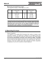
Measuring and switching ranges
These figures are based on nominal pipe size (NPS).
NPS (mm)
8
10
15
20
25
30
Approximate measuring
range (l/min)
water
0.12 - 6.0
0.19 - 9.4
0.42 - 21.2
0.75 - 37.7
1.18 - 59.0
1.70 - 84.8
NPS (mm) Approximate measuring
range (l/min)
water
40
3.0 - 150
50
4.7 - 235
60
6.8 - 340
80
12.0 - 603
100
18.8 - 942
150
42.4 - 2120
Caution! In determining the specified measuring ranges the flow
velocities were based on nominal pipe sizes. However, please note that
depending on the nominal pipe size, the sensor installation depth and
the flow profile, there may be some significant deviations from these
indicated flow values and those in the actual installation.
4. Operating Principle
Theory of operation:
The operation of the model KAL-D electronic flow monitor is based on the
calorimetric principle. The sensor tip is heated to a few degrees above the
temperature of the flowing liquid. When the liquid is flowing, the heat generated
in the sensor is transferred to the liquid, i.e. the sensor is cooled. The cooling
time is an accurate measure of the flow speed. The sensor signal is compared
with the reference data (setpoint) stored in a micro-controller. If the actual flow
speed is less than the setpoint flow speed, the output switches. The microcontroller in the flow monitor allows easy calibration and ideal temperature
compensation to account for variations in liquid temperature.
page 4
KAL-D 10/03
KAL-D
5. Instrument Inspection
Instruments are checked before dispatch and should arrive in perfect condition.
In case of damage, please inform your local Kobold office or if you had the parcel
delivered by a parcel service, contact your parcel service / forwarding agent
immediately, since they are responsible for damages during transit. Should the
damage to a device be visible, we recommend a thorough inspection of the
delivery packing.
Scope of delivery:
• Flow Monitor, Model KAL-D
• Operating Instructions
6. Mechanical connection
Before installation
• Make sure that the actual flow speed corresponds to the switching range of
the device.
• Make sure that the maximum process pressures and service temperatures
specified for the device will not be exceeded.
(See “Technical details”)
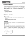
Installation
Mount the sensor in the pipe and ensure that the tip is covered by the liquid to be
monitored. The sensor tip must extend at least 5 mm (better > 5 mm) into the
pipe (see below).
Mounting position
The sensor can be mounted in any position, provided that the pipe is completely
filled with the liquid to be monitored. The installation position must be free of
swirling and turbulence (the recommended inlet and outlet pipe runs 5x the
diameter of the pipe with straight pipe sections immediately upstream and
downstream of the sensor). If it is expected that the liquid will leave deposits in
the piping, the following mounting position is recommended (see figure below).
KAL-D 10/03
page 5
KAL-D
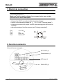
7. Electrical connection
Caution! Make sure that the electrical supply lines are de-energized when
connecting the device!
Make sure that the supply voltage of your system is the same as that
specified on the device nameplate.
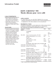
• Connect the KAL-D according to following wiring diagram.
• Switch on the operating voltage (24 VDC ± 10 %) (see "Technical details").
• Check the electronics for proper function (the switching-point LED must be
blinking).
• Adjust the setting of the flow monitor (see "Putting in operation").
Pin 1
Pin 2
Pin 3
Pin 4
+Vs / 24VDC
n.c.
GND / 0VDC
Switch out
n.c.
GND
2
1 +Vs
3
Switch
4 Out
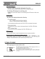
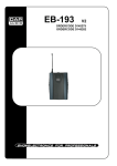
8. Function elements
(View with cover removed)
SET button (3)
Potentiometer (4)
LED strip (1)
DUAL LED (2)
page 6
KAL-D 10/03
KAL-D
LED strip display (1)
The strip of LEDs (8 segments) displays the flow value:
• The flow value is shown on the strip of LEDs, starting at the left.
The blinking LED displays the switching point:
• When flow is at the flow setpoint, the switching-point LED starts to blink more
rapidly.
DUAL LED (2)
The DUAL LED display indicates the following:
• The switching point:
Red = ALARM (actual flow below setpoint))
Green = FLOW (actual flow above setpoint)
In the standard operating mode, the DUAL LED is constantly illuminated
• Setup mode display
If an adjustment (zero or span) is being performed, the DUAL LED blinks
green.
• Error message display
In the event of an error message, the DUAL LED blinks red.
SET button (3)
Press the SET button to start the adjustment (zero or span) procedure.
Potentiometer for setting the switching point (4)
The potentiometer is used to set the switching point. Depending on the
potentiometer setting, the location of the blinking LED on the LED strip will
change. The potentiometer is also used during the setup mode.
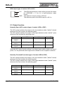
9. Type of output
PNP output (type of contact: (N/O or N/C)
1
+Vs
4
3
KAL-D 10/03
GND
The PNP semiconductor output either outputs +24 VDC or
is high-resistance (open circuit).
The maximum output current is 400 mA.
The reference point of the PNP output is GND (GROUND
= 0 VDC)
page 7
KAL-D
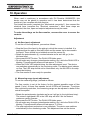
NPN output (type of contact: N/O or N/C)
1
+Vs
4
3
GND
The NPN semiconductor output either grounds the output
pin (GROUND = 0 VDC) or is high-resistance (open
circuit).
The maximum output current is 400 mA.
The reference point of the NPN output is +24 VDC.
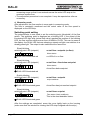
9.1. Output function
Normally Open (N/O) contact (type of contact: NPN or PNP)
The N/O contact switches the output to the low-resistance state ("switch" closed)
whenever the flow is above the switching point.
The N/O contact switches the output to the high-resistance state ("switch" open)
whenever flow is below the switching point.
actual flow >
setpoint
actual flow <
setpoint
power supply
failure
PNP
"switch" closed
NPN
"switch" closed
DUAL LED
green
"switch" open
"switch" open
red
"switch" open
"switch" open
off
Since the N/C switch function will go to an alarm (open switch) state on a loss of
power, it is the preferred switch logic when a failsafe or loss of power is desired.
Normally Closed (N/C) contact (type of contact: NPN or PNP)
The N/C contact switches the output to the low-resistance state ("switch" closed)
whenever the flow is below the switching point.
The N/C contact switches the output to the high-resistance state ("switch" open)
whenever the flow is above the switching point.
actual flow >
setpoint
actual flow <
setpoint
power supply
failure
page 8
PNP
"switch" open
NPN
"switch" open
DUAL LED
green
"switch" closed
"switch" closed
red
"switch" closed
"switch" closed
off
KAL-D 10/03
KAL-D
10. Operation
When used in machinery in accordance with EU Directive 89/392/EEC, this
device may not be placed in operation until it has been determined that the
machine in use complies with this directive.
First install the sensor (complete the "Mechanical connection"), then connect the
electrical lines (complete the "Electrical connection"). After these steps are
completed, the zero, span and setpoint adjustments may be made.
To make the settings on the flow monitor, unscrew the cover to access the
controls.
Adjustment
a) No-flow (zero) adjustment
To set the no-flow adjustment, proceed as follows:
• Stop the flow of the liquid in the piping in which the sensor is installed. It is
important that the pipe is filled with liquid and the sensor tip be immersed in
the liquid. There should be no bubbles around the sensor tip.
• Rotate the potentiometer (4) counterclockwise as far as it will go (to the
left-hand stop).
• Now press the SET button. The DUAL LED blinks green.
• Do not make any changes (potentiometer setting, etc.) while the DUAL LED is
blinking. This adjustment phase will last approx. 5-15 sec.
• When the DUAL LED stops blinking, the zero adjustment is set. The device
now switches automatically to the monitoring mode. The display must indicate
no flow. The LED strip should not be illuminated; only the first LED in the strip
should be blinking.
• The flow monitor is now ready for operation.
b) Measuring range (span) adjustment
To set the measuring range, proceed as follows:
The flow monitor is set at the factory for the greatest possible range of flow
speed (2 m/s). At lower flow speeds, not all 8 LEDs will illuminate. To achieve
finer monitoring resolution, the measuring range can be adjusted to better fit the
actual flow speed.
• Rotate the potentiometer clockwise as far as it will go (to the right-hand stop).
The extreme right-hand LED in the LED strip will blink. Set the desired
maximum system flowrate.
• Now press the SET button. The DUAL LED blinks green.
• Do not make any changes (potentiometer setting, etc.) while the DUAL LED is
blinking. This adjustment phase will last approx. 5-15 sec.
• The span adjustment procedure is now complete. The device now switches
automatically to the monitoring mode. This adjustment has set the device
KAL-D 10/03
page 9
KAL-D
measuring range so that it now extends across the entire LED strip at the
maximum system flow.
• The adjustment procedure is now complete. It may be repeated as often as
necessary.
c) Measuring mode
After adjustment, the flow monitor is once again in measuring mode.
The flow is constantly monitored and the actual value of the flow speed is
displayed on the LED strip.
Switching point setting
The potentiometer is now used to set the switching point (threshold) of the flow
switch. The switching point is displayed as a blinking LED. If the extent of the
illuminated LED light strip (actual flow value) reaches the position of the blinking
LED, the flow monitor switches over from ALARM to FLOW. This can be seen at
the display: the DUAL LED that was showing a steady red light now switches to a
steady green light. The output is also switched at the same time.
Slowly blinking
switching point LED (setpoint)
ΟΟΟ⊗ΟΟ ΟΟ
actual flow < setpoint (no flow)
Alarm status
⊗ DUAL LED illuminated red
no LEDs lit = no flow
Slowly blinking
switching point LED (setpoint)
actual flow < flow below set-point
⊗⊗⊗ΟΟΟ ΟΟ
Alarm status
light strip actual value
Actual flow below setpoint
⊗ DUAL LED illuminated red
Quickly blinking
switching point LED (setpoint)
⊗⊗⊗⊗ΟΟ ΟΟ
actual flow = setpoint
output switches
light strip actual value
⊗ DUAL LED illuminated green
Actual flow has just reached setpoint
Slowly blinking
switching point LED (setpoint)
actual flow> setpoint
⊗⊗⊗⊗⊗⊗ΟΟ
light strip actual value
Flow status (ideal conditions)
This is the most desirable status.
⊗ DUAL LED illuminated green
After the settings are completed, screw the cover tightly back on the housing
(make sure that the window for viewing the LED strip is aligned with the strip.).
page 10
KAL-D 10/03
KAL-D
11. Error Messages
The sensor element itself is monitored for short circuits, open circuits and
electronics failure. Should a fault occur, this will be indicated by a red blinking
light at the DUAL LED and the LED strip display. In this event, contact the
KOBOLD service department.
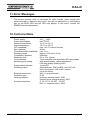
12. Technical Data
Power supply:
Power consumption:
Ambient temperature:
Liquid temperature:
CIP compatible:
Max. pressure:
Time delay before availability:
Switching range:
Temperature gradient:
Response time:
Flow indication:
Switching point setting:
Output status indicator:
Switching output:
Electrical connection:
Protection type:
Housing material:
Process connection:
KAL-D 10/03
24 VDC ±10%
max. 3.6 W
-20 °C to +60 °C
-20 °C to +80 °C
max. 140 °C without function
40 bar
max. 12 s
approx. 0.04 m/s to 2 m/s
Unlimited
5.6 to 12 s, typical
Trend indication with 8-position LED strip display
With potentiometer, optical indicator on
LED strip display (blinking LED)
1 dual LED
Semiconductor, PNP or NPN, max. 400 mA,
short-circuit-proof, N/O or N/C contact,
set at the factory
M12 x 1 plug connector
IP 65
Housing: stainless steel 1.4301
Housing cover: stainless steel 1.4301
G 1/4, G 1/2, 1/4 NPT, 1/2 NPT
M12 x 1, stainless steel 1.4404
page 11
KAL-D
13. Order Codes
Example: KAL-D1408 N ST3
Connection
Model
Type of contact
Electrical connection
G 1/4
KAL-D1408 ..N=NPN/N/O contact ST3= plug connector M 12x1; 24 VDC
G 1/2
KAL-D1415 ..P=PNP/N/O contact
1/4 NPT
KAL-D5408
..M=NPN/N/C
1/2 NPT
KAL-D5415
..R=PNP/N/C
M 12x1
KAL-D0412
14. Maintenance
This device is maintenance-free. The sensor tip should be checked for the
presence of mineral deposits (lime, etc.) and cleaned if necessary.
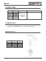
15. Dimensions
Fitting size
M 12x1
G 1/4
1/4 NPT
G 1/2
1/2 NPT
page 12
Length
Wrench size
mm
mm
40.5
40.5
40.5
40.5
40.5
19
19
19
27
27
KAL-D 10/03
KAL-D
16. Declaration of Conformance
We, Kobold Messring GmbH, Hofheim-Ts, Germany, declare under our sole
responsibility that the product:
Compact Calorimetric Flow Monitor
Model: KAL-D
to which this declaration relates is in conformity with the standards noted below:
EN 50081-2
1994-03
Generic emission standard
EN 61000-6-2-2
2000-03
Generic immunity standard
Also the following EWG guidelines are fulfilled:
89/336 EWG
Electromagnetic compatibility
Signed:
date: 29.06.02
H. Peters
KAL-D 10/03
M. Wenzel
page 13