1
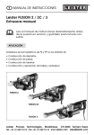
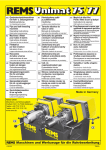
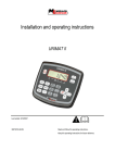
®
GB
OPERATING INSTRUCTIONS
Leister UNIMAT V
Automatic hot-air welding machine
Please read operating instructions carefully before use
and keep it for further reference.
APPLICATION
Overlap and tape welding of coated fabric covers, foils with or without fabric
reinforcement, homogenous or coated sealing membranes made of PVC-P, PE,
TPO, ECB, CSPE, EPDM, PVDF etc, PE coated fabric tape.
Leister UNIMAT V
Automatic Overlap Welding Machine
Leister UNIMAT V
Automatic Tape Welding Machine
Welding seam width 20 or 40mm
Welding seam width 40 or 50mm
Leister Process Technologies, Riedstrasse, CH-6060 Sarnen / Switzerland
Tel. + 41 41 662 74 74 Fax + 41 41 662 74 16 www.leister.com [email protected]
1
WARNING
Danger! Unplug the tool before opening it, as live components and connections are exposed.
Incorrect use of hot air tools can present a fire and explosion
hazard, particularly in the proximity of flammable materials
and explosive gases.
Danger of getting burned! Do not touch the heater tube and
nozzle when they are hot. Let the tool cool down. Do not
point the hot air flow in the direction of people or animals.
Only connect the tool to a socket outlet with protective
earth conductor. Any disconnection of the protective earth
conductor, in or outside the tool is dangerous!
Use only extension cord with a protective earth conductor .
VORSICHT
230
200
FI
The rated voltage stated on the tool must correspond with
the mains voltage.
For personal protection, we strongly recommend the tool to
be connected to an RCCB (Residual Current Circuit Breaker)
before using it on construction sites.
The tool must be operated under supervision.
– Heat can ignite flammable materials which are not in view.
– Interference can impair the welding process when taking
place in the vicinity of high-frequency installations.
Protect the tool from damp and wet.
Approval Marks
Protection Class Ι
TECHNICAL DATA
Voltage
Frequency
Capacity
Temperature
Air flow
Static pressure
Noise emission level
Drive speed
Dimensions L×W×H
Dimensions L×W×H
Weight tape
Weight overlap
2
V~
Hz
W
°C
l/min.
Pa
L pA (dB)
m/min.
mm
mm
kg
kg
CCA certified
230
Mains voltage is
50 / 60
not reversible
3680
20 – 620
500
50 – 100 % adjustable
max 5000
70
1.5 up to 12
600 × 415 × 310 tape
600 × 430 × 310 overlap
28 incl. 5 m cable
23 incl. 5 m cable
WELDING PARAMETERS
Leister UNIMAT V
Welding temperature
Set welding temperature by means of buttons H , – + . The temperature is
dependent on the material and ambient temperature. The SET value will be shown
on the display (5). Switch on heater by pressing buttons + and H (simultaneously). Heating up time is approx. 5 minutes.
Heating
H
Cursor in display blinks.
–
+
&
+
SET value setting
ON/OFF
H
Welding speed
Set the welding speed depending upon the foil or sealing membrane and weather conditions by pressing buttons – + . The SET value will be shown on the
display (5).
Drive
–
+
ON/OFF
M
Airflow
SET value setting
H
2×
–
+
Display appears after
approx. 5 seconds.
Reset
Welded length
*
M
&
+
Heater/drive active
3
DESCRIPTION OF TOOL
Overlap 20/40 mm
2
Leister UNIMAT V
24
5
20
4
22
3
23
1
21
12
26
18
10
17
19
9
28
8
13
30 29
11
31
16
25
15 14
27
32 7 6
1. Mains cable
2. Housing
3. Main switch
4. Keyboard
5. Display
6. Sensor
7. Locking screw for sensor
8. Hot air blower
9. Welding nozzle
10. Tool holder
11. Locking lever
12. Drive/pressure roller
13. Guide roller
14. Pinch roller
15. Drive belt
16. Steering wheel, chassis
Detail A
Detail B
17. Guide roller
18. Eccentric guide roller
19. Guide roller lever
20. Weight
21. Carrying handle
22. Guide handle
23. Guide handle fixing screw
24. Holder for mains cable
25. Lifting device
26. Lifting device lever
27. Lifting device steering wheel
28. Guide shaft tool holder
29. External supporting bracket
30. Guide shaft locking screw
31. Supporting bracket for adjustment
screw
32. Sensor cover
Detail C
12
35
–
1 – 2 mm
4
9
17
45
m
m
Tarp
1– 2
mm
12
Tarp
39.5 mm
BEDIENUNG
Überlapp 20/40 mm
Leister UNIMAT V
Operating condition
• Attach guide handle (22).
• Hang mains cable (1) into holder for mains cable (24).
• Check basic setting of guide roller (17) and welding nozzle (9) (ex works Detail A,B
and C, page 4).
The distance between welding nozzle (9) and drive/pressure roller (12) has to be
35 - 45 mm depending on thickness and characteristic features of the material.
The optimum welding speed has to be determined by welding tests.
• Transport setting
– Swivel guide roller (17) upwards by operating guide roller lever (19).
– Lift up the automatic welding machine by operating lifting device lever (26).
– Move out hot air blower (8) by pulling locking lever (11) and swivel it upwards
until it locks.
• Connect tool to the mains. The mains voltage must correspond with the rated
voltage stated on the tool.
Tool positioning
• Position automatic welding machine correctly on tarp or foil (Detail C, Page 4).
• Place drive/pressure roller (12) on the tarp to be welded by operating lifting
device lever (26) and drive/pressure roller (12).
• Swivel guide roller (17) down by operating guide roller lever (19).
• The automatic welding machine is now resting on the guide roller (17) as well as
on the drive/pressure roller (12).
• Guide roller (17) and drive/pressure roller (12) have to be positioned parallel to
the edge of the foil (Detail C, Page 4).
Welding procedure
• Set welding parameters, see Page 3.
• Welding temperature has to be achieved.
• Carry out a test weld in accordance with the material manufacturer’s welding
instructions and national guidelines or regulations.
• Check the test weld.
• Pull locking lever (11), lower hot air blower (8) and position it between the overlapped sheets until it stops. Locking lever (11) must be engaged. Drive motor starts
automatically.
If an automatic start does not take place, adjust sensor (see Automatic Start Fault
Cause, Page 13). Machine can also be started manually using button M .
• Automatic welding machine is guided by means of guide roller (17). Adjustment
for deviations by using guide handle (22). Do not put pressure on guide handle (22)
as welding faults could occur. Note position of guide roller (17).
• After welding process, pull locking lever (11), move out hot air blower (8) up to the
stop and swivel up until it locks
• After welding is completed, switch off heater with buttons + and H (press
simultaneously). This allows welding nozzle (9) to cool down.
• Switch off main switch (3).
5
DESCRIPTION OF TOOL
Tape 40/50 mm
Leister UNIMAT V
2
5
36
4
22
20
24
35
23
33
3
21
34
26
12
1
18
17
9
10
19
37
28 11
8
29
30
32
7
31
6
27
16
1. Mains cable
2. Housing
3. Main switch
4. Keyboard
5. Display
6. Sensor
7. Locking screw for sensor
8. Hot air blower
9. Welding nozzle
10. Tool holder
11. Locking lever
12. Drive/pressure roller
16. Carrying handlel
17. Guide roller
18. Eccentric guide roller
19. Lever guide roller
20. Weight
21. Carrying handle
22. Guide handle
23. Guide handle fixing screw
24. Holder for mains cable
25. Lifting device
26. Lifting device lever
27. Lifting device steering wheel
28. Guide shaft tool holder
29. External supporting bracket
30. Guide shaft locking screw
31. Supporting bracket for adjustment
screw
32. Sensor cover
33. Tape guide
34. Tape guide fixing
35. Tape de-reeler
36. Tape de-reeler wing nut
37. Indicator roller
Detail E
Detail D
Detail F
12
Tape
12
35
45 mm
6
2 – 3 mm
17
9
25
37
Tarp
138.5 mm
Tarp
33
12
Welding
tape
OPERATION
Tape 40/50 mm
Leister UNIMAT V
Operating condition
• Attach guide handle (22).
• Hang mains cable (1) into holder for mains cable (24).
• Check basic setting of guide roller (17) and welding nozzle (9) (ex works Detail D,
and E, page 6).
• Transport setting
– Swivel guide roller (17) upwards by operating lever guide roller (19).
– Lift up the automatic welding machine by operating lifting device lever (26).
– Move out hot air blower (8) by pulling locking lever (11) and swivel it upwards
until it locks.
• Connect tool to the mains. The mains voltage must correspond with the rated
voltage stated on the tool.
Tool positioning
• Position automatic welding machine correctly on tarp or foil (Detail E, page 6).
• Pass welding tape through tape guide (33) and under drive/pressure roller (12)
(Detail F, page ).
• Place drive/pressure roller (12) on the cover to be welded by operating lifting
device lever (26).
• Swivel guide roller (17) downwards, by operating lever guide roller (19).
• The automatic welding machine is now resting on the guide roller (17) as well as
on the drive/pressure roller (12).
Welding procedure
• Set welding parameters, see Page 3.
• Welding temperature has to be achieved.
• Carry out a test weld in accordance with the material manufacturer’s welding
instructions and national guidelines or regulations.
• Check the test weld.
• Pull locking lever (11), lower hot air blower (8) and position it up to the stop.
Locking lever (11) must be engaged. Drive motor starts automatically.
If an automatic start does not take place, adjust sensor (see Automatic Start Fault
Cause, Page 13). Machine can also be started manually by using button M .
• Automatic welding machine is guided by means of indicator roller (37). Adjustment for deviations by using guide handle (22). Do not put pressure on guide
handle (22) as welding faults could occur. Note position of indicator roller (37).
• After welding process, pull locking lever (11), move out hot air blower (8) up to the
stop and swivel up until it locks.
• After welding is completed switch off heater with buttons + and H (press
simultaneously). This allows welding nozzle (9) to cool down.
• Switch off main switch (3).
7
DISPLAY OPTIONS
Leister UNIMAT V
Operating condition
• Connect automatic welding machine to the mains.
• Start tool in Main Mode or Control Mode.
Without accessory voltage measuring module
1
3
2
4
1
3
2
4
Main – Level
Main switch (3) ON
5
Display of:
1. Welding speed
2. Welding speed
3. Temperature
4. Temperature
5. Welded length
Control – Level
ACTUAL value
SET value
ACTUAL value
SET value
ACTUAL value
–
&
+
&
Main switch (3) ON
Display of:
1. Welding speed
2. Welding speed
3. Temperature
4. Temperature
5. Welded length
8
ACTUAL value
Power consumption in % after start
ACTUAL value
Power consumption in % after start
ACTUAL value
5
DISPLAY OPTIONS
Leister UNIMAT V
The retro fitting of a voltage measuring module may only be carried out by an
authorised Leister Service Centre.
With accessory voltage measuring module
1
3
5
2
4
6
1
3
5
2
4
6
Main – Level
Main switch (3) ON
Display of:
1. Welding speed
2. Welding speed
3. Temperature
4. Temperature
5. Voltage
6. Welded length
Control – Level
ACTUAL value
SET value
ACTUAL value
SET value
ACTUAL value
ACTUAL value
–
&
+
&
Display of:
1. Welding speed
2. Welding speed
3. Temperature
4. Temperature
5. Voltage
6. Welded length
*
ACTUAL value
Power consumption in % after start
ACTUAL value
Power consumption in % after start
ACTUAL value
ACTUAL value
Heater/drive active
9
CONVERTING
Leister UNIMAT V
• Do not touch nozzle when hot
• Switch off heat by pressing + and H (simultaneously). This allows welding
nozzle (9) to cool down.
• Switch off main switch (3).
• Remove mains plug from the mains socket.
Change the welding nozzle
– Overlap welding 20 mm to 40 mm
– Tape welding 40 mm to 50 mm
– Overlap welding to tape welding
2
1
1. Countersunk screw M4 × 10
2. Welding nozzle
Dismantle welding nozzle, sequence no. 1-2
Assemble welding nozzle, sequence no. 2-1
Converting tape 40 mm to 50 mm
– Change welding nozzle
– Change drive/pressure roller
1.
2.
3.
4.
3
Cylindrical head screw M10 × 25
Tension washer
Drive/pressure roller
Adjusting spring
Dismantle drive/pressure roller, sequence no. 1-3
Assemble drive/pressure roller, sequence no. 3-1
2
1
4
– Converting tape guide
1.
2.
3.
4.
Cylindrical head screw M5 × 12
Countersunk screw M4 × 10
Distance roller
Tape guide roller
4
Dismantle the tape guide, sequence no. 1-5
Assemble the tape guide, sequence no. 5-1
3
1
10
2
CONVERTING
Leister UNIMAT V
Converting tape to overlap
10.
11.
12.
13.
14.
15.
Spacer sleeve
Cylindrical head screw M8 × 30
Track wheel
Cylindrical head screw M6 × 35
Supporting bracket
Indicator roller
(loosen on square neck)
16. Cylindrical head screw M6 × 12
17. Cover
18. Plate lifting device
19. Countersunk screw M6 × 20
20. Guide roller lifting device
21. Disc plug
– Change welding nozzle (see page 9)
– Tape 40/50 mm
1.
2.
3.
4.
5.
6.
7.
8.
9.
Cylindrical head screw M5 × 12
Tape guide
Cylindrical head screw M6 × 12
Tape de-reeler
Cylindrical head screw M10 × 25
Tension washer
Drive/pressure roller
Adjusting spring
Axle (loosen on square neck)
Dismantle automatic tape welding machine sequence no. 1-21
Assemble automatic overlap welding machine sequence no. 15-1, Page 12
5
6
7
4
3
8
14
9
square neck
2
1
13
10
19
20
18
17
16
20
21
12
15
11
square neck
11
CONVERTING
Leister UNIMAT V
Converting overlap to tape
– Change the welding nozzle (see page 9)
– Overlap 20/40 mm
1.
2.
3.
4.
5.
6.
7.
8.
9.
Cylindrical head screw M10 × 25
Tension washer
Drive/pressure roller
Guide roller
Drive belt
Locking washer D8
Pressure roller
Cylindrical head screw M18 × 16
Steering wheel, chassis
10.
11.
12.
13.
14.
15.
Cylindrical head screw M5 × 40
Cover
Plate lifting device
Countersunk screw M6 × 12
Steering wheel lifting device
Adjusting spring
Dismantle automatic overlap welding machine sequence no. 1-15
Assemble automatic tape welding machine sequence no. 21-1, Page 11
1
2
9
8
4
3
13
5
14
12
11
10
14
15
6
7
12
FAULT FINDING ACTIONS
Leister UNIMAT V
Error 100 /101/102
Massnahme
check the
blower
• Check blower (air must flow out of nozzle)
• Error re-occurs, contact Service Centre
Without accessory voltage measuring module (Control Level)
Display 4
Cause of heater defect
Action
100 %
100 %
• Low mains voltage
• Heating element failure
Reduce airflow
Repair/Service Centre
Cause of drive defect
Action
• Low mains voltage
• High welding speed with
large load torque
Reduce welding speed
Check automatic
welding machine process
& SET value
not reached
Display 2
1
100 %
With accessory voltage measuring module
Display 3
Cause of heater defect
Action
SET value
not reached
• Low mains voltage
• Heating element failure
Reduce airflow
Repair/Service Centre
Display 1
Cause of drive defect
Action
SET value
not reached
• Low mains voltage
• High welding speed with
large load torque
Reduce welding speed
Check automatic
welding machine process
Display of:
1. Welding speed
2. Welding speed
3. Temperature
4. Temperature
6. Welded length
3
5
2
4
6
ACTUAL value
SET value
ACTUAL value
SET value
ACTUAL value
Display of:
1. Welding speed
2. Welding speed
3. Temperature
4. Temperature
5. Voltage
6. Welded length
1
ACTUAL value
Power consumption in % after start
ACTUAL value
Power consumption in % after start
ACTUAL value
ACTUAL value
1
3
2
4
5
13
FAULT FINDING ACTIONS
Leister UNIMAT V
Cause of automatic starting defect
Drive motor fails to start automatically after nozzle has been pushed into position
• Sensor (6) incorrectly adjusted
Action adjust sensor
–
–
–
–
–
–
–
–
–
Switch off main switch (3)
Remove sensor cover (32)
Lower hot air blower (8) and move to left hand stop
Locking lever (11) must be engaged
Loosen locking screw for sensor (7)
Push sensor (6) onto tool holder (10) (switch displacement, 0.5 mm)
Tighten locking screw for sensor (7)
Assemble sensor cover (32)
Move hot air blower (8) up to the stop and swivel upwards
If FAULT still exists, contact the Service Centre
3
8
12
10
32
14
7
6
®
BA UNIMAT V/11.2005
ACCESSORIES
• Only Leister accessories should be used.
• Voltage measuring module
–The retro fitting of a voltage measuring module may only be carried out by an
authorised Leister Service Centre.
TRAINING
Leister Process Technologies and their authorised Service Centres offer welding
courses world-wide free of charge. The customer will also receive training on site
if necessary.
MAINTENANCE
• Clean welding nozzle (9) with wire brush.
• Clean air inlet on hot air blower (8).
• Check mains cable (1) and plug for electrical and mechanical damage.
SERVICE AND REPAIR
• When display (5) indicates "maintenance, servicing”, the tool must be checked
by an authorised Service Centre.
• Repairs have to be carried out by authorised Leister Service Centres only. They
guarantee, within 24 hours, a correct and reliable repair service using original
spare parts in accordance with the circuit diagrams and spare parts lists.
GUARANTEE AND LIABILITY
• Guarantee and liability are in accordance with the guarantee certificate as well
as with the currently valid general business and sales conditions.
• Leister Process Technologies rejects any guarantee claims for tools which are not
in their original condition. The tools must never be altered or changed.
Technical data and specifications are subject to change without prior notice.
Your authorized Service Centre is:
Leister Process Technologies, Riedstrasse, CH-6060 Sarnen / Schweiz
Tel. + 41 41 662 74 74 Fax + 41 41 662 74 16 www.leister.com
[email protected]
15
®
Servicee Record Leister UNIMAT V
This document should be handed to the authorised Leister Service Center for
updating when repaired or serviced. This document is to be retained and kept
by the owner of the tool.
Technical Data
Automatic hot air welding machine Type
Order Number
Serial Number
Rated Voltage
V
Ratet Power
W
Sold
Date
Service
1. Date
Service Centre
Signature
2. Date
Service Centre
Signature
3. Date
Service Centre
Signature
4. Date
Service Centre
Signature
5. Date
Service Centre
Signature
6. Date
Service Centre
Signature
1. Date
Service Centre
Signature
2. Date
Service Centre
Signature
3. Date
Service Centre
Signature
Repair
Leister Process Technologies, Riedstrasse, CH-6060 Sarnen / Switzerland
Tel. + 41 41 662 74 74 Fax + 41 41 662 74 16 www.leister.com [email protected]