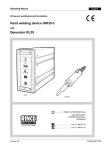
1
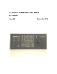
Operating Instructions ABW35 Deutsch with SL / RL generator Disclaimer The information in this brochure corresponds to our current state of knowledge. However, it is not to be understood as a warranty for certain characteristics or for suitability of the products for certain applications. Our general contractual terms apply in this regard, and reference should also be made to these terms with regard to liability. No industrial property rights of any kind are granted to the user along with this brochure, nor are any assurances made with regard to a licence. Corresponding separate agreements would be necessary for this purpose. The suitability of the products for particular applications may only be checked with our own specialists. The German version of the brochure is binding with regard to accuracy of the information given. 2 Copyright by RINCO ULTRASONICS AG, Switzerland Version 1.0, gb, Art.-No. 39034 Operating instructions established with: ABW35 SL35-600 RL35-400 Creation date: 06.11.2009 Notes Read and precisely follow the information in this operating manual before unpacking the unit and putting it into operation! The unit may only be used, maintained and repaired by people, who are familiar with the operating manual and the applicable regulations on work safety and accident prevention. Representative 3 Content 1 Safety 1.1 1.2 1.3 6 Explanation of symbols and signs Safety information Noise emissions 2 Transportation 2.1 2.2 2.3 2.4 Unpacking / receiving inspection Damage during transportation Placing the unit Site location and work place creation 3 Product information 3.1 3.2 3.3 3.4 3.5 The entire system Press Oscillator unit Booster Generator / control 3.5.1 Generator SL 3.5.2 Generator RL 4 Initial operation 4.1 4.2 Power supply and connections Operation and display elements 4.2.1 Welding press 4.2.2 Generator 4.2.2.1 Generator SL 4.2.2.2 Generator RL 5 Starting up the system 5.1 5.2 5.3 4 Welding operation Starting up the generator 5.2.1 Generator SL 5.2.1.1 Parameter setup 5.2.1.2 Description of setting parameters 5.2.2 Generator RL 5.2.2.1 Detailed description of functions from the program selector switch 5.2.2.2 Process programming Adjustment 6 7 8 6 Maintenance and service 6.1 6.2 Cleaning the machine Fuses 6.2.1 Generator SL 6.2.2 Generator RL 27 27 29 29 30 10 10 10 10 11 12 12 12 13 13 14 14 14 15 15 16 16 18 18 19 21 21 21 21 22 23 23 24 25 7 Service Addresses 31 Important! When you make enquiries about your machine we ask you to state the exact type of designation and serial number of the unit. You will find these details on the type plates (A and B) on the side of the press as well as on the back of the generator. ABW35: Press with 745 N max. force The construction and electric installation of these devices are subject of continuous development and improvement and represents the latest state of technology. RINCO ULTRASONICS AG Romanshorn, Switzerland A Preface We are very pleased that you chose to buy a RINCO product. We are convinced that you will achieve a maximum degree of economy of operation and product quality when using this unit. The purpose of this manual is to give the purchaser and the user all the information they need in terms of the handling, assembly, operation and care of the welding press. To ensure that your system is always in an operational state, you should take note of and follow all the tips and instructions contained within this manual. B These instructions describes the ultrasonic welding machine ABW35 in operation with a generator SL35-400/600 and RL35-400/600. A B 5 1 Safety 1.1 Explanation of symbols and signs A system of symbols indicates dangerous behaviour as well as correct behaviour. The symbols are used in the operating manual. All danger and note symbols describe conditions, during which people, things or the environment could be put at risk, if these symbols are ignored. Danger symbols in the operating manual are structured according to a unified schema. Structure of the danger warnings Note! Especially important information or operating notes for problem-free operation. Caution! Denotes a danger warning. Ignoring this warning can lead to severe injury or damage to parts of the unit. Danger! Denotes a severe danger warning. Ignoring this warning can lead to death or severe injury. 6 1.2 Safety information General The construction of this unit represents the latest state of technology and is safe in operation. The individual components as well as the complete unit have been checked by our quality control department prior to delivery. Intended purpose The welding unit is intended exclusively for the ultrasonic welding of the plastics for which it is suited. Different use or use beyond that does not count as intended use. The producer does not accept any liability for damage caused by unintended use. The user bears sole responsibility. This system is intended for industrial use! Unintended use • • • • • • • Using the system with insufficient knowledge of how to operate, maintain or care for the system. Altering the welding system and the generator with, for example, attachments or conversions that could influence the safety, without the approval of RINCO ULTRASONICS. Making modification in the control software! Using unsuitable working materials. Opening the generator housing during operation. Handling the converter while energised. Allowing a second person to operate the two-hand start button Choosing stuff Only trained and instructed personnel should perform work with the cutting unit. The responsibility of the personnel to operate, set up, maintain and repair the equipment is to be clearly defined by the operating company! The operating company must make sure that only authorised personnel use the welding unit. Work on the electrical equipment of the welding unit may only be carried out by trained electricians according to electrical regulations. Work on the pneumatic equipment may only be carried out by trained personnel who are qualified and experience in the field of pneumatics! Installation Danger! Do not attempt to hook up the equipment when it is plugged in! The electrical connection is to be earthed in all cases! Country-specific, statutory safety measures must be followed during installation! If these regulations are not respected, the producer refuses to accept any liability for personal and property damages! The equipment must be put in a closed and secure state each time before it is put into operation. Only use dry compressed air for operation. If necessary, an air service unit can be added. Important note Before putting the machine into operation, carefully read the operating manual in hand. The operating manual is to be kept near the welding system, where it can be accessed! 7 Operation 1.3 Noise emissions Caution! Caution! Under no circumstances should the generator or the Limit value: according to current understanding, converter housing be opened during operation of the ultrasonic causes no damage when the maximum welding system. level remains below 140 dB and the median level, referring to 8 hrs/day, remains under a linear 110 dB. Danger! High voltage prevails inside the device – risk of injury! • • • • Refrain from any and all possible methods of work which may put safety at risk! Only operate the welding system when all protection and safety equipment, e.g. detachable protection equipment, emergency stop button, noise insulation, are present and functional. If safety measures such as sound proof cabins are not ordered and used by the customer, the manufacturer accepts no responsibility for any damage which could have been avoided, had such equipment been used. Before switching on the welding press, make sure that no one can be harmed by the starting press. Pay attention to the sub-harmonic, i.e. audible pulsations, that, depending on use, fluctuate greatly and have an annoying and harmful effect. Here, the standard measure is the equivalent sound level Leq over a representative working period (at least 8 hrs/day, max. 2000 hrs/year), with a maximum level of 85-87 db(A). When welding special materials, the 70 dB (A) sound level may be exceeded. Counter measures: • Wear ear protection • Install a sound hood (optional) • Operate with sound enclosure (Information according to SUVA, the Swiss Accident Insurance Fund, no. 86048 d 4.94) For more measured values see “Sound Measuring Protocol in the RINCO supplements” no. 920-3903/1.95 Danger! During normal operation, the two-hand start buttons are to be actuated by one person using both hands. The manufacturer accepts no liability for any personal injury or damage to property caused if the dual safety switch is operated with the help of another person or in any other way other than the correct way. • maintain the operational readiness, • increase the life of the device and • reduce down time to a minimum. 8 Guarantee RINCO ULTRASONICS delivers the system with a guarantee that corresponds to VSM (Swiss Association of Machinery Manufacturers). The conditions for RINCO ULTRASONICS fulfilling its guarantee are, among other things, the following: • The user possesses knowledge of the contents of this operating manual. • The instructions and warnings in this operating manual are followed. • The operating company is not permitted to undertaken any changes or conversions of the individual parts of the press, the oscillator system or the generator of its own accord. RINCO ULTRASONICS is happy to explain any possible ambiguities or to provide instructions by our qualified staff via telephone. 9 2 Transportation Equipment may only be transported by suitably trained personnel. Please note the transport advice on the packaging. The press and the generator should be transported separately. 2.1 Unpacking / receiving inspection The transport container for machines and equipment can withstand normal wear and tear resulting from road, rail and air transport. Upon receipt of the delivery you should check for completeness of all parts listed on the packing list and that there is no visible damage. If there is any damage you should immediately contact your transport company and retain the packaging as evidence. 2.2 Damage during transportation Any damage that has been caused during transport is the responsibility of the haulier. In order to substantiate the claim, a complete report with an accurate description of the damage must be submitted to the haulier as a basis for the claim. Any damage or loss of goods provided by ourselves is to be reported to us immediately, sending a copy of the above report as confirmation. If the delivery from RINCO ULTRASONICS AG was «free house» or CIF, the damaged delivery will be replaced and the appropriate claim made under the relevant transport insurance, provided the respective conditions are met. 2.3 Placing the unit The ABW ultrasonic welding machine is designed for a: • Placement on a table • Mounting on a table • Mounting on a wall For the mounting of the unit, there are provided four mounting holes. 10 2.4 Site location and work place creation The ultrasonic welding machine ABW35 is designed for a normal, clean industrial environment. The following descriptions of work place creation is a proposal and derived from the valid international norms for industrial work places. 11 3 Product information 3.1 The entire system 4 The entire system consists of: 1 Press 2 Generator / control 3 Anvil 4 Converter 5 Booster 6 Horn 5 6 1 3.2 Press Drive Double-acting cylinder, diameter 40 mm • Tool stroke maximum 6 mm • Power at 6 bar 745 N • Throat depth 66 mm • Precision ball track on the sliding actuator carriage • Switch for upper cylinder position Ultrasonic Working frequency, 35 kHz Energy • dry, compressed air, maximum 7 bar (105 PSI) Weight • 12 Weight, 11.2 kg (without generator and oscillator unit) 492 mm 2 3 156 mm 120 mm 3.3 Oscillator unit 7 4 Converter Example 5 Booster Converter: 5 µm Booster: 1:2 10 µm Horn: 1:3 30 µm 6 Horn 7 RF socket Lemo 1 Amplitude gain The amplitude can be correspondingly amplified by various booster and horn designs. The individual elements are mechanically connected by means of a screw thread. The tightening torque for 35 kHz systems comes to 15 – 25 Nm. We recommend using the RINCO tool wrench. 4 5 Converter = 5 µm The allowable operating temperature lies between 10° C and 50° C. Booster = 1:2 10 µm 3.4 Booster For RINCO 35 kHz welding units, the following booster types are available: Booster colour material 1:1 1:1.5 1:2 green yellow white titanium titanium titanium 6 Horn = 1:3 30 µm Connection screw thread • On the converter: M8 • On the horn: M8 Before mounting, the coupling surfaces have to be cleaned. Parts with damaged coupling surfaces need to be replaced. If heat production is too high, greater than 50° C, the converter needs to be cooled with compressed air. 13 3.5 Generator / control 3.5.1 Generator SL Technical data • • • • Dimensions (WxLxH) Power classes Connected loads Connection • Display • Weight 130 x 450 x 300 mm 400, 600 W 230 V, 50/60 Hz Mono pashased Power supply Power bars and status LED 7 kg 3.5.2 Generator RL Technical data • • • • Dimensions (WxLxH) Power classes Connected loads Connection • Display • Weight 14 130 x 450 x 300 mm 400, 600 W 230 V, 50/60 Hz Mono pashased Power supply Power bars and status LED 7 kg 4 Initial operation 4.1 Power supply and connections Take the following steps to put the equipment into operating condition: 1. Anchor the work table and screw on the press on the back side. 2. Connect the cables between the press and the generator. 24 23 21 22 25 Danger! Only use an earthed electrical connection. 3. Insert the unit plug into the socket on the generator: 21 22 23 24 25 STO1 Actuator STO2 Start STO3 Interface STO4 Converter connection STO5 Power (electrical supply) Only on the RL generator, the power switch is on the back board. The generator SL is switched at the front. Compressed air connection 7 bar maximum; 105 psi. 4. Connect the compressed air hose (21a) to the available compressed air mains. 21a 15 4.2 Operation and display elements 4.2.1 Welding press 1 Converter housing (8) The oscillator system together with the electrical supply line is located in the converter housing 2 Horn (6) The horn is the actual welding tool. It is tuned to the resonant frequency by the producer. 12 Warning! Never alter the tuned horn by making mechanical changes. This can cause damage to the oscillator 9 8 system and the generator! 1 Anvil (3) 6 Rapid centering and fastening of the anvil with the supplied attachment screws. Attachment screws actuator (12) The attachment screws of the actuator allows most accurate alignment of the anvil (3) and thus also the alignment to the horn face (6). Microswitch (10) By the exert of the microswitch the welding cycle will be activated. Warning! Country-specific, statutory safety regulations must be followed during installation! Note: If these statutory regulations are not adhered to, the producer refuses to accept any and all liability for personal and property damages! 16 10 3 3 Pressure regulator (13) The pressure regulator holds the air pressure on the top side of the piston constant and is set to a height which depends on the size of the piece and the length of the weld joint as well as on the material to be welded. As a point of reference, a regulated pressure of approx. 1 [bar] can be set on a typical section with a welded seam of 2mm x 10mm. 13 14 11 Throttle (14) The throttle has two functions: • Speed of the machine stroke. • The temporal power structure when the sonotrode has touched down on the workpiece. Stroke limitation (11) With this screw, the stroke limitation is to be set at a safety distance of 6mm. The stroke must be delimited on max. 6mm. This ensures that the operator can not reach in the tool range during the welding operation. This precaution serves the operational safety and must not be removed or altered structurally! 17 4.2.2 Generator 4.2.2.1 Generator SL 30 Handle for generator module 31 This handle is used to withdraw the generator module when required. The fixing screws (31) for the opening of the generator module are located above and below the bar of the handle. 30 32 36 37 Never attempt to withdraw or insert the generator module while it is connected to the mains network! 34 35 (High voltage)! Do not touch the printed circuit 38 33 board – the capacitor carries high voltage! 30 32 LED bars This display indicates the output provided during the welding process. With no load on the horn (free oscillation in the air), the display should not indicate more than 25%. If the 100% mark is exceeded, an error message appears. After the welding process, a flashing LED indicates the maximum output (peak). 31 g c PREV 36 2-line LCD display The LCD display indicates: • • • welding parameters error messages and operating states 37 Keyboard These keyboard can be used to • • activate the generator functions change welding parameters a change the programme / welding operation b move to the next programme line c move to the previous programme line d move the digit selection to the left e move the digit selection to the right reduce numeric value g increase numeric value h set value to zero f 18 d h e b CLR NEXT f a SET UP 34 «US-TEST» key Key for activating the ultrasonic test. The display will indicate the current horn frequency. If the key is activated for more than 5 seconds, an error message appears. Do not touch the horn! 35 LED • • • «US-ON» ultrasonic active «VALVE» electrovalve active «ERROR» error exit active 38 «ON/OFF» key 33 «POWER» LED Operating mode display 31 Fixing screws During operation the fixing screws must be fitted properly! 4.2.2.2 Generator RL 30 Handle for generator module This handle is used to withdraw the generator module when required. The fixing screws (31) for the opening of the generator module are located above and below the bar of the handle. 31 30 32 33 Never attempt to withdraw or insert the generator module while it is connected to the mains network! (High voltage)! Do not touch the printed circuit board – the capacitor carries high voltage! 32 LED bars This display indicates the output provided during the welding process. With no load on the horn (free oscillation in the air), the display should not indicate more than 25%. If the 100% mark is exceeded, an error message appears. After the welding process, a flashing LED indicates the maximum output (peak). 34 35 40 41 30 31 33 «POWER» LED Operating mode display 19 34 «US-TEST» key Key for activating the ultrasonic test. The display will indicate the current horn frequency. If the key is activated for more than 5 seconds, an error message appears. Do not touch the horn! 35 LED • • • «US-ON» ultrasonic active «VALVE» electrovalve active «ERROR» error exit active 40 Welding time With this key, the welding time can be changed. With the initialization at the internal program switch (level 9), the welding time can be increased by the decuple (99.9s). 41 Hold time With these buttons, the hold time can be changed. 31 Fixing screws During operation the fixing screws must be fitted properly! 20 5 Starting up the system 5.1 Welding operation Through the activation of the micro switch the welding cycle will be activated. The actuator pulls out and the ultrasonic starts immediately. The ultrasonic stops according to the parametrized time. After the parametrized hold time, the actuator goes back to the resting position. 5.2 Startup of the generator 5.2.1 Generator SL The following standard settings are reccomended for this application: • Start: Automatic • Trigger: Off • Welding: Timer • Valve: On • End switch: Off • Afterpulse: Off (application dependent, for «dieing away» On) • Soft start: 7 • Language: German ( Country dependent ) • Amplitude: Intern • SDF: Off • Earned limit: Off 5.2.1.1 Parameter setup According to the initialization of the generator, there are parameter settings available. They can be changed if required. For activating the parameter setup see following page Adjustable parameter Setting Part counter Welding time Hold time Trigger After-pulse Amplitude Performance limits After impuls [ADJUSTING :] [PART :] [WELDTIME :] [HOLDTIME :] [TRIGGER :] [AFTERPULSE :] [AMPLITUDE :] [PERFORMANCE MIN :] [PERFORMANCE MAX :] [AFTERPULS :] It is advisable to record the respective changes in a setup log in, in order to be able to return to existing settings whenever necessary. 21 5.2.1.2 Description of setting parameters Setting [ADJUSTING :] – Press both start buttons within 0.3 seconds to lower the actuator. Keep the start buttons actuated until the safety switch is reached. Press the start buttons again to move the actuator back to the home position. Part counter [PART :] – The part counter steps up by one, after each sound welding. Press CLR key to reset part counter. – Maximum display: 9999999 Welding time [WELDTIME :] – Duration of welding. – Setting range: 0.00 – 9.99 s – Standard setting: 1.00 s This parameter is operative only if the function [WELDTIME: TIMER] is operative in the * SYSTEM-INIT *. Hold time [HOLDTIME :] – Upon exipation of the welding time the horn keeps exerting pressure on the welding object for the HOLD TIME. – Setting range: 0.00 – 9.99 s – Standard setting: 1.00 s 22 5.2.2 Generator RL The RL generator can be started up through the power switch (25) on the back. At the startup of the device, a system test will be executed. With this the efficiency of the oscillator system will be verified. With the «US-Test» button, the function system test can be repeated. 24 23 5.2.2.1 Detailed description of functions from the program selector switch Ultrasonic devices are used in a wide range of fields today, so that users have a variety of different control requirements. A welding installation needs to be able to be connected to the available peripheral devices. For this reason, a number of programmes have been created to suit the most common peripheral requirements. These programmes are permanently installed in an integrated computer and can be preselected via rotary switches. The program selector switch is deliberately located on the card module (see fig.) inside the housing in order to prevent unauthorised changes to the program. 21 22 25 31 Before a program modification 1. Disconnect the unit from the power supply. 2. Unscrew the 4 fastening screws (31). 3. Take out the generator module by pulling the insert grips (30). 31 30 30 23 The program selector switch has 10 adjustable modes. For this application we choos program 8 «automatic» is selected. 5.2.2.2 Process programming The welding- and holding time, as well as the soft start time can be parameterized: 40 Welding time With this button, the welding time can be changed. • Increas digit value • Decrease digit value With the initialization of the internal programm switch (level 9), the welding time will increas by ten 31 times (99.9s). 30 41 Hold time With this button, the hold time can be changed. • Increas digit value • Decrease digit value 32 33 34 35 40 41 30 31 24 5.3 Adjustment 11 Installing the oscillator system 12 Caution! Always switch off the power supply to the generator, before installing the oscillator system. (Power OFF)! The setting takes place in an unpres- 12 9 surized state (pressure regulator 0 bar) and without cover. 1. Screw on the horn (6) with the provided special 6 15 spanner (A), a flatspanner (SW 18 mm) or a adjustable spanner to the oscillator system (4-5) and tighten the screw carefully. Tightening force 15 - 20 Nm. The oscillator system is ready for operation. 2. Open the cover plate (9) of the converter housing. 3. Plug in the RF plug at the RF connector (7) of the converter. 4. Insert the oscillator system from the front in the converter housing. 5. Close again the cover plate (9) of the converter A housing and thighten the two screws with the allen key (SW 6 mm). It should be possible to turn the oscillator system with little effort. 6. Align the horn (6) parallel to the anvil (3), then moderately tighten the screws of the cover plate (9). Pay attention to uniform distribution of gabs between converter housing and cover plate. 25 Caution! If the horn is not precisely aligned, the micro switch (10) can get damage. 7 7. Hold the actuator and loosen the 4 attachement screws (12) with a socket wrench (SW 10 mm). Push the actuator completely to the top and fasten it by means of the screws. 9 8. Loosen the screws of the limit plate (15) and after move the limit plate completely back. 6 9. Put the adjustment caliber on the anvil (3). 10 15 3 10. Loosen the screws (12) and carefully place the actuator on the adjustment caliber, lightly press it down and thighten all 4 screws equally. If the welding image becomes unequal during the welding process, if necessary, the parallelism between horn and anvil has to be readjusted (point 7 - 10 ). 11. Loosen the counternut of the stroke limitation (11) and turn counterclockwise until the horn (6) can be put on the anvil (3). Clamp the feeler gauge 0.2 mm between horn and anvil and turn the stroke limitation clockwise until resistance is felt. Tighten the counternut. Check the resulting air-gap. The air gap should be 0.2 mm. 11 12. Adjust the limit plate (15) to the desired welding distance ( 3 - 10 mm ) and tighten the screws. 12 26 6. Maintenance and service 6.1 Cleaning the machine 1 Caution! Cleaning and maintenance work may only be carried out by trained personnel. Before beginning the maintenance work, make sure that all power sources, such as electrical power and compressed air, are 2 disconnected. Never clean the keyboard or the display with acidic cleaners. The multipress and the generator do not require any special maintenance. 6 3 However, regularly cleaning the: • Press (1), • Generator / control (2), • Anvil (3), • Horn (6), guarantees a long and problem-free operation of the press system. Pneumatic unit After work disconnect the compressed air supply. Lubrication system Maintenance-free. Generator Always keep the generator display clean. 27 Oscillator system Danger! Work on the oscillator system and converter housing only if the supply voltage is switched off! High voltage! Avoid contact with the RF socket of the converter. Do not connect any measuring device to the RF socket of the converter! The converter contains an electrical charge even after the generator has been switched off! Screw connection Converter (4), booster (5) and horn (6) are screwed to each other. Tightening torque: 15 – 20 Nm Black spots on the surfaces of the booster (5) and the horn (6) can be easily removed. 1. Lay a polishing rag on an flat surface 2. Draw the black spots over the polishing rag. 28 6.2 Fuses 6.2.1 Generator SL The following components are fitted with fuses: Mains socket Bus print Generator module Dimensions of all fuses: 5 x 20 mm. 6.2.1.1 230 volt fuses Generator GM35-400 GM35-600 Mains socke Busprint Generator module F1 F2 F3 F4 F5 4A/T 4A/T 4A/T 4A/T 400mA/T 400mA/T 4A/T 4A/T 100mA/T 100mA/T 29 6.2.2 Generator RL The following components are fitted with fuses: Mains socket Bus print Generator module Dimensions of all fuses: 5 x 20 mm. 6.2.2.1 230 volt fuses Generator UGF3 35-250 UGF3 35-400 UGF3 35-600 30 Mains socke Busprint Generator module F1 F3 F4 F5 3.15 A/T 4 A/T 4 A/T 400 mA/T 400 mA/T 400 mA/T 3.15 A/T 4 A/T 4 A/T 100 mA/T 100 mA/T 100 mA/T 7 Service Addresses The RINCO ULTRASONICS AG technical service agents are happy to answer any questions you may have concerning any technical malfunctions or welding problems which may occur. For an efficient response our Customer Service requires the following information: – A precise description of the technical fault or cutting problem. Our address: RINCO ULTRASONICS AG Industriestrasse 4 CH-8590 Romanshorn Switzerland Tel. ++41 71 466 41 00 Fax ++41 71 466 41 01 www.rincoultrasonics.com [email protected] 31 32 Date Carried out work Person in charge Note 33 Date Carried out work Person in charge Note Industriestrasse 4 CH-8590 Romanshorn 1 Switzerland Tel. +41 71 466 41 00 Fax +41 71 466 41 01 34 [email protected] www.rincoultrasonics.com A CREST GROUP COMPANY RINCO ULTRASONICS AG