1
\
,-i , i
i
I
/l
SKYMAP" AND TRACKER'"
INSTALI-ATION & OPERATING INSTRUCTIONS
CONTENTS
WARNING
:)!
the
The GPS system is r: =-7-:t
government of the .:-:ej S:;--=s '.:iich is
solely respons ible for . :: i-ll:ac) and
maintenance. The sl' s:a- ,s under
development and is subject :: ::.::irS r*hiCh
could affect the accurac)- arC :::: OfmanCe
of ali GPS eauipment.
Although Sk.vmap't'Fr and Traci^c: ' are
precision navi gation aids. anl' ia\ aid can
l're risused or misint-erpreted. t hereby
understand
manual and
using the i:.
the
un i
1-
a
J
1
4
5
.
6
uP.
6
S
B
B
any
The al:,::de calculnted by Skymapr{ :s
geome:::,: :eight above mean sea level ard
could ,. åri' s igni f icant 1;r f rom a1t i:r"r.de
displa: ea ii) pressure altimeters.
NEVER se GPS altitude for vertical
navigation or terrain clearance.
omiss-c:s therein.
3
of batter"v tYPe.
1
OPERATION
Yap custotrri,atjoii.
Displal' adjustments.
!lor.ing Yap display.
i0
Fil-e nearest.
11
Receiver status.
l2
Displap' icons .
12
\avigation.
13
hal'point capture.
13
Storing r.a;'points.
14
Building a route.
15
Clearing a route.
15
Reversing a route.
l6
Fl;,ing a route.
17
GOTO mode.
Approachins ha:'Points. 1B
19
Demo mode.
discrepanc ies before cantinuing navigation.
This equipment is not a replacement for
your chart and js intended as an ald to \-FR
navisa---on_!nry. The database ulthl: the
equio:e:: has been compiled from the latest
offrc^a- information available. and
a1tr,:ug: eve ry care has been taken i n the
comp-la:.on. the manufacturers wiII not be
held :esconsible for an)' inaccuracl' or
Ohoice
Data input set
ai:ua- use, carefully compareindicatli,is i:oir 5'our SkymäPTr't o. Tracke:'to a1. ai a: lable navigation sources
includii'q ::.e information from otner
navaids. '. -sua, sightings, charts, etc '
always resolve
1
TRACKER.I'M SETL P
at your own risk.
-isk. carefull;.' review and
aspects of ihis oh'ners
:.-,uSh1-r' practice oPeratiorr
:ode prior to actual use.
safetl'.
INSTALLATION
Yount l ng
h'hen ii
For
2
Connecting an externai
supply.
Data input connection.
Lse Skymap'rx and Tracker'H
t i:-'
2
Special features
Inserting batteries.
becoming unsaie.
Tc :?d,::e
II{TRODUCTION
TECHNICAL
Sk-vmaprM
APPENDIX
APPE|\D I X B.
APPEND]X C.
APPEND I X D.
i F]
CÅT IOI\
r'iY.
20
Skymapfr data ou:put. 2L
Clearing down nenorl'. 21,
22
How does GPS vo:i?
GPS
status info.
Service and Gua:aliee.
\TAPI\S ISSUF] 3
t,-OR
SPEC
& Traciie
COPYRIGHT SKY'FORaL
USE h I TH SOF-TWARE VERS I O\
24
24
l994
2.00 i\D Allovt'l
0NI-Y
INTRODUCTION
nov -the o\dner of
Congratulations ' you areitate'C
:.et simpleone of the most öopf itt todal" \aturally'
to-use Navaids u"äiiuUlt
get it r^o^rking but
'
vou can't wait 1o -spar.e a feu moments
prått
do,
tefore you
to read- through this manuar '
it and
'lhe time you spend reading throuBh
.l-tit the, features of
f amil iarising yJ""t"lf
'"U1"
repa''O b1' trouble-free
vour unit 'if f
satisfaction at
ooeration ancl "";;;;å;ter
j
sirccessf u I nav igaL on
'
vour unit
\o matter rnhich ke1' 1'ou,at^:,tt'^ti,'
functrons
Tr)' ou.t all I3::,Tä;:
cannot be Oamageå'
get
If luu 5cu
hnrrr u'orrr-inE' 1t
worrling'
rrrrr
;;ä";;";;..t
+^-h nf
"i*'out
-'..r
^i'offf
switch
llv
into a mess, siml
onol, ,u reset al1 functions'
-vou
and back on
SPECIAL FtrATURES
IO
SELEDT OPTII]IT
Hiddenwithinthedisplayb,t-1.ta:efour
seque::-'--1 shoot
infrared emitters that
ac,ro;.; ::" f ace of
beams of invisiUf " iigi't
itä ältpraY to a single rece--'':''
'. -.,: f inger
hhen )'ou touch th9 scree:
,:. - a:d the
breaks one of the beamsr.i:c- -: :l'::: -'-'r keY
;;;;;;"; can determine )'our f inger is on '
ieed for
This sl'stem completell rer''''t=,.t:t
(v: r their
anl' mechanical 'uitth"=a:d ensures the
-arä'
inherent unreltuUiiiti'i
alual's avai lable '
correct lunctiontof a single ke;''
v'hen needed, at tie ioucn
this
r:caii/ sPecial- feat:ure of'
'
The other
is the disPlaY screen'
brand ner' kind of
The screen used is a (LcD')
r'n, r giYes T\'
equiPment
uni'que and ver)'
a
llr is equipmenL l'eaLures
år"r'åä'r-it"touchrY'
ng"tl':iH
;
t.-rt
i
sr^
spt't' i a I
avionics
tras been pioneererl in
LiLetouchr',
'
i;,
';;:'::å?;i?:
l:"'
t;;;;;::.
lhe man-macnlne i"";'..",*"'?"
of use to a
bri r,ging extreme ease system for the
5ppir i st icated "ät'fg"if*
,,,,,'rr.t, lked Pilot '
for
'.:rt':r:'it'ip1c is'lthl'
ver)'' slmple' ^0ne ke'veas!.
as
is not hor'ever
t'i:," ltili', irlit
are manv different
there
as . - sounds since
wi th u
, ii:c i r ons u.ro.iåt"d
'o"phitticated
usinB e
-'{
iiill) nut''gäilun t,}'lt"I^'..,and
:',r
result in a ver)
ci)l\ r'ni jonaf i"eipatl t"ouid
larse number of ke'vs'
having
over the problem ofabe
r- - ieiouch'r'M gets
I Ied
of keYs ' e^ach ke;rs wi
- ar qe numbers
th
j i'i;.";,;ii'. b-v ha"'ing o.nIl1-llu-:
the
on
Ltrd' change
;.. j;' fri"t
'aoeis
':;;"in o"qtit'^ii
display mode'
a-raiiable functit
"åti
tle disPlaY.
ne ke1's are actua1l5' drawn qnare ac t ivat ed
and
l,r;r.,';'h; iigt t hand side'
relevant part o f
the
.,1"'iten,ii'låutr'ing
L
--:e disPlal' screen'
Iiquid cr;'slal jdjtpiui
tube tvpe c I ar #;;; ::1",-.il*^-:'i:: with
:??l-:a
iåT Jlffr;'.^ät,J uä.iLieht:9"'-:ed
"=,::Ti:::
black/white ."'0""!!ti.^s lt1i.
.'cerIent
si::s
-!'
:å::Xå:t1" ;;i5"'ä;;i'"'
;;;;;;; in most lighting cond'.t':, t-= - -- ,''.lI:
In addition the display
irite
cf'a111:"
Dl Lrr\. 1 blact<
":*^"-- r^-.1 iåäaär.
mOOeS. either
;nitg
i
'
uää[ä.or.a, ideal .f ": d.1
'::characters on a black back5:
{ IOUI-}d
White character: j^1^ o ,. " .- . . ,,. nlgr-, :, I li.gi::
{no\dn as lrvcrrL
: :: ''-:rl
a1
an
iI*" op".at ion be.c.au1e^,..
'' '
=d to
å*iitåä uv the disPla:
night
.{
' "i
äuiåirte tninlmu*' her'r=
vision.
:.
_
?H';å:F.H:"::';",''-'
the perlorllliltlLtr "- '.: -1jj;l:,'i::
:nk vou fo
_.-i"'r-.^åov
to take this oPPo::
an
-'.:
haPPY and
l:,:"1",,1ih'"# ; :safe hours
f11
're
'
=:-
When the batteries become J-ow, a warning
message will be given across the screen.
When this message appears, switch off as
1. INSTALIATION
The first
::- :g to be
cons
soon as possible.
idered
is
TRACKER BATTMIES
establishing a ,:a,;e: supp11' :o l-our unit.
Primarl, oohe: s::u d be de:-r ed fron an
- Jr-t \ j- _ .
- :.: ?::.4 external sour-c:
batteries. 1: . --. 1=:. shou-j:- :=-aa::=j :s
being suitable ::: ::IDO:a:i l: ::a:ge:li'
use only.
Ensure the unit is switched off and the
external power lead is disconnected.
,
0pen the cover on the back of the unit
by rotating the recessed screh'anticlockwise.
i a:ol,ce
th Tracke r''"
disposable or re::=::=.: - =
fresh set of Li:::o: ::::.: -:s aan give uP
t o Lh ree t imes mo re 'i,!: :: - - .1 --ie than a
fuily charged set of ni-ca:s . -:ternal dr;o:
Wi
cells
can not be used
in
Si
.
-oJ
if you have a Trackerfr aid choose
dry'
LithEon L91 high energy lithium
:atteries must be used. Ordinary alkaline
types such as Duracell are not capable of
ce1ls,
six AA cells into the spring
loaded battery holders, negative end of
each battery to the spring terminal.
Snap
Ensure the batteries are inserted the
correct way round theit replace the
battery cover and tighten the screw.
-l,
UCAR
supplying the current required for
than a few minutes at a time.
more
- i ;'ou have a TrackerrY, h'e recommend you
fit a fully charged set of ni-cad batteries
and wi re -.he oower input connector to a1low
a contr:uous trickle charge (see r.iring
diagrar li -:.age .1) . In the event of an
exter:.a co;e: suppl:' failure, the n^-cads
note: If you have a TrackerrM and
intend to use it in conjunction H'ith a GPS
that rel ies on the externa l supply to
produce a ciata ou lput ( such as <r iäCll
mounted Garmin 100), fitting batteries is a
waste of time as the GPS will stop sending
data in the er-e:t of a power failure.
Please
a
-^-i-.
wt11 -. rrtr:"
ior use and automa:-ca11y
:- kit containinB sir rigir
take .,i'er.
.,.'I',t
rpart \o. SYP 516). aid a
purpose - - : - -- -:s adaptor.'batterl' c:arger
(part \,. qrr: : -- a:e ar-allable fro: 1-our
EXTER}JAL SUPPLY
capac - :;,'
Skyfo rce j--rrC-:
-
- -
-
If you have a Si."::;}. :---: z: :z::::-=s are
alreadl- f itteri a:j s:-,..i-: := i':--i- c:arged
( 15 hours )
us i:g
::: :a-rs adaptor
supplied. The trics.e .:a:ge l:ri i-:hin
the DC pov/er lead is aiieadl- coi:e::ei.
NOTE1 h'i th both Sklrapr and
TrackeilTIlh-e trickle charge dörir:ed irom
the aircraft supply is sufficient ol,1'to
maintain the charge level of the ba::eiies,
\01 io actually charge them. The ba:teries
mus: be fully charged before the unit is
i, --ed in the aircraft.
PLEASE
If internal batteries are being used, the
:isplay brightness should be reduced to an
absolute minimum in order to get any useful
lrfe out of the batteries.
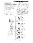
Supplied with )'ou: urit is a pre_ wired
connector. If lour ui:: is a SkymaprM, the
cable ri11 have tL'G cores and no screen.
If your unit is a l:ac.:er*, the cable will
have fou: corcs a:d : s::een.
The red
are for
i0
and
a:d : j3
t_C
:t-
c,--,rrS : l e-:her cal:le type
:-i: :: a:.i'DC supply between
:s . :a:a: -: c: supplying 1
Amp.
*' LU-..-:^^--- --
-
io-:
D'I
-:--.'a -:-
:
:j-
s-:.
x coilec
i- i sr
-r :he negative
:;e: source.
You na1- a, qn -1,-LP" \'.:'q,
L4
\ U. ,
adap:e: is
:az2Ampfuse
i.:ia10-30
aU:Ola3r-e
:i'
--- ,-rsing a L2 or
cigar lighter
:.
i - :1e as above
.
1
IX+I DATA OUT
2
Tx-J(sxYunP
93
84
7S
66
4
3
2
1
cores are the data
The velloH
"ii*= ,andi'eIgreen
is
lor' is DArA -and greenand
1;;"i
RS422
paiÄ-cnotu. The inPut is RS232'
§IEA Cr8'? comPatible'
or §{EA device'
\rher cc:recting to an RS232
-';ilr; should go to DATA (A lilti and green
oNLY)
DATA GROUN+TRACKER
oNt-v
Rx
DATA
-.1
(B Iine)' \'!tn
å;å'";.;;ä"t-t" eiouno
device ' : eLlow
Rs422
ä
to
co:rec: -ng
to TX* ' The
green
srcu^: go to tXI and
go to ground'
=.t.t. ihould
GROUND
TRICKLE CHARGE
8 AIRCRAFT POWER
LINK
6 AND 8
WHEN NICADS RTTED'
E1'.-aro l:
To connect to a staid alone
| ' connect
P:.':.a\ or Garmr n .GPS 100 Jlr'"I;Eji
ti:e:rackerru
tire g:een core änd:screen-of
of tht ; ier/data
i..c=.i'in. utacI cot"
'o: tr',.
the i =- -ot+ core
connect
cps '
;;;-.
to the 1 e - ; core o f
o i ::e Traclrer"r i"uä
tha ;':'"er ldata cable '
trr'=-e 2i
To connect io a C::' -: '"-alion
L.\o--_L
-'
L.aG*"^L
if using ni-cad
Iink to ft':"a"
[äi i"tT"t (TrackerrM on]f i '
O"
showing
WARNING
CHARGE
NOT BE
LINK.
O)iCE Tt{E EIpJ<LE
(Trackerft onIY):
"r'tADs,
Lliriiril
"pirtso
spEli
DRY c!!!.q^Musr
REI''IovING THE
wITHoLIT FIRsr
-
'
__.-.
DATA INPUT
(Trackerffi onIY)
'
'l'racker'' "t requires a data
-1o
GPS uni t in otä*
";l
r.....:..." t"t1
@::c
6;-1^,,1-ir of tne 1ti.
:;;; .. pin J3 (r\'
::'--t:-^^:1:
:'-- ,: l::assts
i':-:-:--
:":
1e1Lot*
to a :!ig'-:'j!5-"=
Era-:-. 3: To conleci
gfeen C':e zt:d SCrr'.'
,\-\'::r
r \''.--'" rcrnfleCL
'""1'.--iv ine to the clac^ core ii
oi the Tracker" Lead oi
tl" G-Ps,' Connect
the poweri'data t;;it rrackerr':
I eaci ro the
the yei I ow co' t u?"iie
cable
'
;;;wn-.oi. o I the POuer '/data
input from another
function' whilst
and
is a iul 1 GPS receiver
other
drive
to
;:';'J;X,",'ä oäta'*outp"t
connection for
equipment
"is (data output
cotered in APPendix A) '
s;ilä;iFra-e"i"-rPj: ;:)"T;ti . ; ;, J':
unit' :'ou
äi:il
':i ,';;--r 1f 1'ou are instailing a.Trackerw
core ofr rthe
coloured
cores'
-,L,
cabl e, and Lhe
=
uill have two "iiia"caute
Lrrc
ol
core
l
to the
a braided screer
vel I cu and green
' and inPut
yellow core : ,a-= t'-t"et* cable
io:
'the''
cables
cable'
daia
i;å;;" ;;;
yellow core ':': ':' - --ghtmate PC
GPS'
to
)our
connection
TNL
" :-r':-ect to a Trimble
Example 5:
48t- i
an
requires
the
sreen
'1'o operate f uJ- I;" Tracker'|M
:.srzz t ' ,.r"i:::
ääifto _: : : :_-'l'\f
containing
sentence
data
the screen to Plns
0lB3
\\IirÄ
baud
'
core to Pl:- spee'i
ground
i'r pin 3
track'
"miot*ution with an R\lC
Ia:::ur'le. longitude'
13/14 (0r ' a.'l. ihe yellow core
an,l .'ai-iaLion
qt ternailu"l'" u 9600. baud Trimble
hea,Ji: r' .
'1'ranspakll. l'rimUie f(l-' Cutnrin AIL or Kinq
-\E
TRACKER CABLE
may be used'
,OWER
equiralent ARNA\; R-30 sentence of
GPS
'
1'our
output
it''"
SJPPLY
I I in rloubt uUoui'
Oa
i,,nio,,i i'nrr deaier or the GPS manufacturer
olr)
erf)
for iiilrice.
(na
o(9(,
jon
e
back
insulat
cabLe
*2.
.--'. i tir the ouier
braid
o=
<i'.i,i''L rna;'' and puI I back the screening
--l o
covered
plastic
iout.-inn"r
Ltle
:Li i'('\eal
Et
of the cable
corcs. 'lhe ,.tttni"g trraiO
The
core'
a single
Skvmapr*
; l[:
'
-
o_
sirould be LwittfO'i"t-o
be.connected as
:erl and i,tue cai.llei shouidsection'
You are
l.r.ii[.1r in thti previousconnec t ion to 1''our
r|\r reacll' to makä data
C?S
l
unit.
lrnnect ions to
6: To connect to a Yagellan SKY\-Å\:
SOOO tnSZ:Zt. coanect the green core and
screen to pin i (R5232 ground). Connect
the yetlow core to pin 72 (RSz32 Port
To ensure uninterrupted navigation it is
essential that the antenna has direct line-
TXD).
Radio signals transmitted by the satellites
are of an extremely high frequency and can
be regarded as having approximately the
Example
1
MOI]NTII{G THE I]NIT
a
For those ins:a- -::: a SilaaPrM unit, an
external blade alie::-a r !?l'i No. SMP 512 )
is avai labIe .
as
possible.
same
unit has :,een supplied complete with
gimbal bracket i'ir iired installations.
Your
of-sight contact with as much sky
penetration capabilities as iight.
That is to say, satellite radio signals
will penetrate only verl' thin materials and
will be shlelded by most material that will
block light.
If the position you have chosen is shielded
from the sk1'. there are several options for
remote antenna siting.
The gimbal bracket has seen designed for
easy insertion and remor-a^ of 1'-our unit in
order to facilitate use in another aircraft
or vehicle, home programming and to prevent
The simplest is to use the Skyforce 1 ' 8
meter remote antenna extension accessory
( suppJ. ied as s tandard )
The gimbal bracket supplied may be mounted
on a flat horizontal. vertical or overhead
surf ace.
This accessory a11or.'s the standard antenna
to be mounted up to l. B meters away from
the main unit, held in place by a rubber
suction cup. This is ideal for temporary
use in vehicles and tighl aircraft.
theft.
.
ions include an e.\rernal magnetic
mount antenna kit for ground vehicles and
0ther
an external biade or low profile type
aircraf t a:":e:ra. Contact 1''our Skyf orce
dealer f c: :'.t::her detai Ls
:_nq pos i t ion has been
Once i iie
gimbal bracket securelY
:.
decided. iir
qua
bolts and shake
good
using
- -:i' nuts
wmffi
.
-
proof u'ashers.
cloos--; :-: ;:s-:^:: : -: i-::: unit,
of direct su"uliti:t must irc avoided as
glare will mai*e ::e :-s; -.i --- ii::ul-t to
When
areas
iead and sunlight cirD calrse orerheating
damage
and
to the displa5-.
. :: l-ou are
instalting a Skymap}. is io eisure the
antenna, which attaches r-ertica^r1-to the
:ear of the unit, can see a large area of
::e sky, preferably right dorl. to the
:_:1ZOn.
In order to operate fuI1Y,
!::ilaprM needs to receive signals from at
-:ast four satellites at once.
any time there may be uP to eight
:e.lites in view but the-v could be
.--utely anywhere in the skY'
The other major cons-'Cera:ior.'
opt
IT IS ESSB-Ti..\I- I\ MOVING VEHICLES '
ESPECIALLY AIRCR{FI. TO E}JSTT'RE THE GI}{BAL
BRACKET iS FIR{LY FIXED DOWN.
Both Tracker3 and SkYuaPfr have a
reasonable mass aild could do considerable
danage if they' Lere to break loose under
high G loads or in tu:bulence.
Once ::.=
fixed -:
(beirg :,
and e -;:
fi
x::g
bracle:
care fu the s -.ie
hu::
s
.
tsi:-rl :as Deen securely
----sr:: ::: lor.'er/data Plug
: : -:s.:-.: ::ere is a right
::gnten the Plug
1':,u:i
unit OntO the
::.:
=--::
s-de knobs. Be
lu: iingers between
- cf the case, it
I
. CL
Most stand alone GPS receivers
2.
After establishing a suitabie poh'er supply
for your unit. you ma5' switch on using the
on/oif switch located on the left side of
the case. The dorn'n Position is on'
LP'
need to
be configured to gire an output on their
data 'iräs. Thrs is usually done via the
ke;'pad. -:e GPS should be configured to
TRACKER SETI]P
Touch the panel marked SET
will be disPla;'ed.
will
Screen four
gii'ä iz-e at a repetition rate of two
iecc. :s . -: ls not alwaYs Possible to
unit
seiec: :epet-tion rates, but if your
get
the
to
al-r.;= :lis. it is important
as
seconds
two
da:a - -:put as near to e'n'ery
poss-:-e.
Era-:-es for popular brands foIlow'
or
-e l: To configure the Pronav
llal
the
select
f
irst
ila:-.- cPs too,
b='r- - t:erf ace page. Next move ::e cursor
o\:: ::e cYclic field to the right of'
"O--?,-- anä press the CLR ke: :o select
output format ' \'i:'* :ove the
ti:e l.:'EÅ 0183u0K?'
and press tic -). :e1"
ar.=-: over
Era::
}IAIH
HETUHN TD MAIH ITEHU.
},{ENU
PFDEHAU $/AYPI)INTS ANO Ht)UTEE.
BÅt'lK
DUSTDMIZE AND DEDLUTTEH HAP
lilAP
SELEDT DAIA INPUT
NISP
ADJUST t)ISPLAY UDDE, CDNTBA§T
LDD
\o'* s:-ect
r
s(l
-
reen lour
.
I i GL:.:
rlAP
DI SP panel ' Screen
\orn Louch the
I br: riispla-ved wi th the currentof data
the
i'orrnat setting shown at the bottom
legend'
screen beside the DATA lNPLT:
f ir,,e
wi I
REIUFN TD SEIUP UEIiU.
Mro unitr: NAUT
MILES
DrientrLion:
HDHTH UP
A'iiEld Hamer: ENELISH
To conf i qure the
franspat<tt, first select the SET
Tfrls is reProduced belou
E-IE-nPle--
A'f ield Nrmer: DN
Torn Namec: DN
l-
DOWN
s r:
reert
fl
SET
i ve
l'he lactorl'default setting is N!{EA 0183a
formal. Configure your GPS to outputthe
ralirl dala formai then select b)'
,fp.ooriate tlala- t-rlpe
-kä; on )-our-TrackerTn
.epeutedll: until the
tol.fring the DOWN
'
cr..o. ba. is ct','er the DATA INPUT: legend
will
cursor
The
ke)'.
\erL touch the SET
move Lo the right. Lse the LP and D0l{N keys
lo scrol I through the various data input
options then touin SET again to select the
des i
Trimble
LP menu.
l
- -'-. - - ^.ree can be
-. :-'.::ent OutPut
lus: :e st-.- '=: :o ASCII
The field at the end o ' - -- ',,ur 1s the
output jnterval rate. ::-- : -: - be set to
02s (the s means secondsI - -"' -: order to
-a: ion. the
output correct track
..
:lode. It:
Transpakll must be used -- te ou tPu:
Trimb-.
correctlY. This is a qu-:'- ' .::-:.: on
you:
software. Now select -F"-
The field
selected
formats. Thts
-
1
Heliordr: [)FF
Drur lnpui: NMEA I)lBS
l-rackct
f .t
l
lIG.i\AL-TICALiD.\:t
1-g[=il[+l
G.BRI:Äl\'3i
UP
DN
DN
-
'
5EI
UP
! - 1-
-
AIRi3D
Åitrorre:
Launch Siter:
-:ac''e:
an
I: ::: GPS 100 is :ack :iu::ed .'*t::-.--11\
Ar'-a:,:: interface L'nit tLi' ' 'le ::e GPS
ou::,:i - iormat must be selec:ed ol
ar:i ji-\1. R30 forrnat selecied on !'ou:
ÄND BHIEHTHE§8.
'i'racke
I\YEA 0183 on 1'our
red data inPut
t1'Pe.
TrackerrM.
TrackerrM is connec--= - : :' a Trimble
T\;2000 /2100/3000 or a llage- - =- Ss1'\ar'500C
I
f your
select
ARN R30.
Dala format selected r-'i.i oe heldofii:
."*o.y, even uith the unit sr"itched inpu:
Ii is only necessary to set the data
:] le up once.
Touching
3.
OPERATIOI{
After establishing a suitable power supp11"
for your ur- l . ensure the antenna is
conneited and :r,-rting straight up (SkymaprM
only) , then s'" -:ch on using the on/of f
swi tcli Loca:e,j ,rir the lef t side of the
case. Down is i:. Remember, GPS will not
work indoors. The antenna must have a
clear view of nost of the sky.
display a
When switched ,:,-. ::: __._: ;-ll
titLe screen ar,j ""- - . -: -',,.u to touch one
of the screen pa:ie -s :- s , :eferred to in
this text as ke1'sr. ..= --r::?r u'i11 take a
few minutes to come u,, : -,-- brightness,
especially in co id cond - : - - :-s
.
matter which kel lou ac:-\a:e, your unit
cannot be damaged. Tr)' ou: all functions
No
and features without r*orri--ng but please
iouch onlr,- the si-:ch paiels. T0UCHING
0THER PARTS OF IHE DISPLåY WILL CAUSE
L]\Lr'Ä\TtrD SWITCH F1\CTIO\S
the
panel
marked }IAIN MENl-i
return the display' to screen one.
T0
THIB BDREEH EIVES INFD DH EADH
FUHDIION. TDUCH PAHEL;DB MDHE.
H0HE
DET4D ALLDWE YOU TD UEE T{AP HODE
t]El,{t]
WITH THE BUILT IN SII{ULATI)F.
ltlINE
§ETUP ALLDIVS YDU TD SET DPTIDIIS,
5ET
PRDEBAM IYAYPDIHTT AND Ht)UTES.
UP
MAP M[)DE IS THE HOHIIAL DPEBATIHB
lllAP
UDDE DF §TYHAP.
}Jt]DE
Skymap screen two.
DEIIO }IODE i
s
cove
red on page 1 I
be trl ing to establish pos.ition by
immedia:e11 starting to search the ski for
active saieilites.
Trackerfr '*'.-. be
}IAIN
RETURH TI) MAIH HEHU.
}IENU
PEDEHAI TYAYPDITi T S ANl'] HDUTE S,
DU§TOUiZE AHD BEDLUTTEH IIAP
lookine for^ lncoming data from you: l?S.
ADJIJST D
0n ::e
:r--le
^-.^ -. , .; -e.
d.ld.i_c-
are
H:LP
Skymap'"
TOI.EH SHEE}I
PAIIL
TO SELEDT tlPTIt]N
+
3].AY IilDt]E,
DONTHAST
AND BFEHT}IESS.
Skpmap sc
Skvforce
.
if the panel marked SET tP is touched on
screens one, two or three. screen four wilI
be displayed,
OCCUR.
lrom the momelt oi suitch on, Siilrnaprrr*i1i
will
ree:
iou r
iJÅNi(
T{AP
DISP
LCD
.
U:DE
!fE\I pane. :eturns to screen one. I f
the !t{P DiSP pale' :s touched, screen five
will be displal-ed r"^:: the current setting
shown doun the :rE:: hand side of the
5EI
screen.
[:110
MAIN
UP
HAP
HEIWH TO
SEIP
!Ii\",
Yt]EE
Skymap screen one.
Url uri:rr hAIII Y .EE
D,Lyitthnr hDFTH.l
A'f L
-. :he panel marked HELP is touched. screen
-*-'..ill be displayed giving instructions
:-: :elp on each function.
-lst in screen tr+o the panel marked
is touched, screen three (not
::ated ) wi 11 be displal,ed.
I lltatr:
A''LE Hrr:r:
UP
DX
A:tltcr: l\
H:
UP
E\EL S-
I;rr \r-tl: l\
Lrun;h Sitrr:
5rI
r]NWN
l\
irrdr: J;F
Sk:eap screel iive
SET
The desired measurement
units for your map
miles. statute miles or
i"ärii.ir
orientation
i;1;;lres ) , the map displas'''
or track at
screen
of the
a;;;ih at the top
and-the
moving)
when
i-riå i"p of the ..t""n
or ICAO
names
;;; ;i'pLain rnglish airfield
by moving
.åå"t throughoJi *ui'' be selected
touching the
the cursor uar uJ änd
down'-
;;i i;;-in.n using the LP and Doh\ keys to
select various oPtions'
map display'
In order to declutter the
names
town
' airspace
ai r field oames .
(glider',
sites
Launch
uår"åå.i"t,
and
,iä.åiiet,t and^-[atachute"parls^cend)
on or of f '
rråiip"oä maY be turned
display'
0nce you have customised !-our map
wiII
touch the SET Up päntl and the displa5:
revert to screen four'
Panel - is
From screen four i f the LC?
displayed'
touched. ,..""n i""tn will be
HETURH TD SETUP UENU.
ffi:i+.=",iiffi,:Hill
Fros screetr one i f the
dispial-uiII
the r1§,:i
touched
ffir:;',"r'J
":,'å
ILAP VODE
panel is
ä:"'3.?.'""1"1'i:
show screen eight'
II
I
I
ffiå"I I
T{AIN
TIENU
I r--,-
'ry r-tär'l I
z00H
IN
z00ltl
t]UT
l
INFI]
B l{m
Skymap screen e
MIDi)LE PANEL
ADJUST USINE TDP AND BOTTDI'
to obtain a fix
If the GPS has been unacie
sa
t ime or -ack of satellites'
to lack oi time
tue lo
år"
N0 FIx
word
words
:ne
sno'*::'
be
will
will
;;- *p
;;of
middle
the
a':css the
PÄNEL.
ÅDJUSIIND
BHIGHTNESS
Skymap screen seven.
iös§irir,g r.i11
Fös§rir,g
the
:he screen.
'l'lre second panel from the bottom shows SEL'
you to
'f ir i s s lands f or SIrl.tlc'l- and al lows
chti(tse beLrneen atijusting andbacklight
l:'. tlispial' tt'"nttutt of thedispiaS''
lni,irri 'l'ht'
screen
L('\i al the bottom
moilc.
for
ted
ec
l
se
l,tLs been
ha t
s hor, s
r^
l
adjustments have
display related adjustmer
al1 disPlaY
panel and the
UP
SET
Panel
tåuctr tne
*u0".
.i0".
U"""
=n
our '
i 11 revert to screen ffour
iprul- '*'*i11
äitprulmemory
Contrast adjustment uil-1 be saved inis used'
and be the same ne'tt time the unit are not
I -ni:i level and disPlaY mode
ä;;s;;r;;t
memor.r-. The unit will switch on
saved in'orightness
mode'
iurl orightness in normal mode'
äi iuil
:n
When
l-t-
BELEDT DISPLAY MODE, EDHTRAST
DH dAD( LIEiiT BY Ti]IJEI"iii'iE
ad,i us t mt'n
on a
Standard mode shous black characters
vhite
shows
shov
mode
il"-uu.r,g.ound. Reverse
ilil;-;;.kerorno.
background and is
on a black background
i.å.t".i" o"
characters
use'
night
ral15-preferred for
usua115-Preferred
.
u"T1-l
"'e--: l-r data',
da
un:: la> ".e--:
un::
the
";;
1(
ievel
r:arlr
trrr
3:
disP-ai:i z-'
.l1I:
ulil be älsp-ai=:
;iiT
Position
::=
;:esent
:" :-: ::esen1
:":-:
(i:500,000r''-.::
ii,ioo,ooor'.:.:: ::itt
cen
::' centr"
-: ::e
shown bY a sma-- ::;== -smal I
t
r
a "l-:T:
-J;
u'-"le
nor: r ;;
disptay
disPlaY area ' ncr:
-of
-o
screen
the
of
of
:'::::'r
åi.t.uit icon :ea: :::
{hen
when
(
or
f- )ou r, ish Lo ad just - brightness
CONTRAST'
or
r:ontrasL, selecl BACKLIGHT
'l'ht' t. i Tll and DARK ke1's can be used to
to one of
uä.ir=i the brigtrtness or contrast
to
adjustment
sirteen leveis. L'se contrast
Reduce brightness
äptirnii. vjewing angle' power
to prolong
ii running on batierl'
:e see:
track uP mode '
"
I
1ife.
select
'
;''ou wish to change displal'.19d"
kevs will
DISPLA\' IIODE. if-r. irra unO nanx
to
.nång" to R\;SII and STD' Lse th-ese keys
display
change between."'l"ttt and standard
I
I
mode.
*ffryffilrffil
-t
;
ih: :åi':.',ä"#ii,f ::' i,'lf:*x1
"1
f
in
I
be
statute miLes were selected, GS will GS
selected'
\+ere
MPH. I f^ kilometres
-
11 be magnet ic
wiLI be in Ki;H. Track wi into
account '
with loca1 "ä.iation taken
The
position reporting
Zoom
le"'el
1
Scale bar 90Nm. Shows coast
outlines onlY.
Zoom
1evel
2
Sca1e
1s
is prioritised' If your-position
and
range
airiield'
within five mir"i-oi-an
wi 1 1 be
bearing from inut air field
or
beacon
a
is
åiipralea, even if there nanes are shown
torn näu.".. Atl airfield
p.ä""äåå uv a t- in order to distinguish
ihem fron towrs with similar nanes '
If your position is found to be within five
more than f ive
miles of a VOR Uåton and
will be
miles from an uiiii"ra, posit.ion
beacon' even
shown with respect to the VOR
town nearer' NDBs
if there is an NDII or towns
iast '
have next PrioritY and
outlines, airfield
Zoom
1evel
3
Zoom
level
4
bar 15Nm' Shows coast
fin"t, icons for airfields '
heliPads V0Rs,
one
position u--1 be
,påutLt. the previous
single
shor:r on ,..".n'ln the form of a
dot
.
a trail across the
These dots wiIl
screeo giving u OltJfuv of your his"orical
iract oier the Past five minutes '
displal'ed '
1f , af ter a position has bee1.
PoSSIBLE
FIx
No
the
ii',
iit
i;; GPS loses
buitd up
ui11
;;;';;; iltr ue oisPraYed ' is rhis
to
able
until the unit
;;;ti;;.
off'
recalculate position or is switched
' - the
Whilst screen eight is being di'spJbeai'ed
to
used
ma]'
ZmY I\ antl z0O[ OL-f ke5's
alter the scale of the maP '
the zoom
There are ten levels of zoom' rs ion
wi I linfo.rrat
level is in.."us"d , more table opposite
The
be shown on thå- map'
details this.
& user
heliPad
'
& use waypoint names and
controlled airsPace '
VOR
Zoom
level 5. Scale bar BNm iscalecoast
' Shows
airfield icons &
1: 500 ,000 )
1ines,
names, heliPad icons & names'
VOR icons & names ' NDB icons
town icons & names '
user r*aypoints icons & names
and controlled airsPace'
&
I
NDBs
*ävpäintt, airfield,
measurement.
ke.eping voY' present
uäirä'"ai.Jiiv"al
around it
påti?i", ,iiti and moving the map
d:sPlaY
the
As
pirel at ; time '"
'
Sca1e
of the
at the bottom l-eft hand corner
display is a scale bar showing a
tho - six
The display will be updated ever)'
of data
amount
;;;""d;' (depenoi-ng o; the
icons
VOR icons '
Sca1e bar 30Nm. Shows coast
1ines, airfield icons '
["iip^a icons, voR icons and
controlled airspace '
Also
miles '
The measurement na}-'i be in nautical
on
ing
dePend
i iome t res
sta'uute mi les or r,n
live
'
sclaen
the selection nade
50Nm. Shows coast
helipad icons and
message displayed on
screen
bar
names
'
ievels 6 - iC ' Siiow aiL iniorrri'ition as
i""äl-s Lut without controlted airspace'
Zuom
nap are the
in the
prUfitn.O centres for each item
screen with
äuiuuu." and r"hen disPlaYed onoverlaPs
are
their corresPonding names ' at high zoom
bound to occur. esPeciallY
The icons shown on
the
levels.
i'"'-at.?n airfield
If a clash is iikely,and
NDB' the order of
where there is a-riOR
first ' then
p.iå.riv- it airfield nameswaypoints
and
VORs,
towns.
then NDBs. then uset'
small stubs to
Airfield icons have two
of the main
indi.cate the orientat ion
to. scale and
not
run.."a!'. These ;i;;; are position
of the
do not represent- tn" "ttoal
aid
an
as
intended
main runway' rn"il-uit
joining
circuit
and
to airfieta recog-nition
onll'-.
PLEASE
NOTE: The coast
iiie
shown on the
only to
is for general reference
are o'er land or sea'
iiäi.åI" uhethär !'oushot
twist' turn'
i;"i; G.ssibie io duee'erv
:o memory size
åår"" läa isLand
map
I iml
tat ions
.
At an1,- time *-hi1st displaying screen eight,
the liFO panel may be touched. This w111
cause the display to show screen nine' All
INF0 screens are printed in a large font to
afford high visibility when flying.
is selected, screen eleven wi 1l
be äisptayed with the five nearest NDBs
shown atong vith the BRG (bearing FROM the
aircraft T0 the beacon) and dlstance to the
beacon in the selected units.
If
NDB
INF0
FIYE H EAHE§T NDBr
BI)UTE t)H BDTD MDDE.
NAV
EPB HEDEIVEH STATU§.
EP5
FIYE NEAHESI ITEMS.
ros,
RETURH
llfll;rln
ID UAP.
tDl
EOTE
HNB
t
Atlt
e0E h!
e,l
ililF0
§H0
3Pl
U
(E
1lUH
ÄREA
INE
ilt
ltr
EO
INFO
T,IAP
DLH
rD§r {
HF
D5t
DU
filu I
-THrDr
l,
rrF
DÄ HTEHBI Y
ALT 2EOU
Geographic latitude and Iongitude is shown
at ine bottom of this screen for reference'
is not present on
concerns the
ion
funct
This
1-rackers.
is
deal t with
and
recei'n'er
i nternal GPS
'['he second key down (GPS)
Iater.
this lnformation the position, track'
ground speed and altitude (if available)
BeLor
are displayed.
screen eleven, you can select MAP'
AiD I\FO or VOR INFO. MAP will return to
screen eight at the same zoom level as it
From
was 1eft.
i f the AREA panel is ,rdw toucheri, screen
ten witl be displayed uith the five nearest
airfields shown along with the BRG (bearing
the aircraft T0 the airfield ) and
distance to each in the selected units'
FROY
FIYE HEAHEI
TArrE I
T
AIBF iLDS
BRB
PNB
110H
ztD r{
2t)
INFD
LASHEI{DEI{
eSqM
2,t
NBB
STDNEACHE
EBEM
a2
INFI]
SOUTHEI{D
320 U
EE
051
LYOD
M
THADT 131M
Gg
,l37
ALT
5'ou can
FIVE HEAREST
Bfg
ID
DYH | ',34r
IDHr
FAO
DUE
SIIT
E.a
il2r
DE] EEI ET
LYD I zzzv
DLr{ tr]el
EI
YÅY IEEU tr5
r
fr
2e
35
lE
E
ESDO
select !10R8 INFO '
or !lAP. !L'\P will return
to screen eight at the same zoom level as
it r.'as left.
ten
NDB INF0
each V0R.
lJAP
BeIou this information the position, track'
qround speed and al t i tude ( i I avai lable )
are displa]'ed.
I\F0.
VOR INFO
1
Skymap screen ten.
From screen
is selected, screen twelve will
be displayed r*ith the five nearest VORs
shown ätong with the bearing to (BRG), the
radial (RAt) from and the distance (DME) to
If
MOHE
INFO
B
UAHSTt)H
HB'
Skl map
l:e:aC-a- C.spia1-ed r.ith each VOR is t
aea: i:g :B:t{ lhe \'0R. T0 your presen
positiö;:. i"e- if l-ou are. on- Lht.,11
iadial. !'ou ai-e directl1" south of the VOR
each VOR is th
DYE d ispial-ed
- with
(not slan
ground
orl". the
d i s tance
lhe
d I s:.
ance
)
in the selected units from t
leacon to J,-our present Position.
ic
t/lÅP
ES le7
Straap screen eleven.
Skymap screen n1ne.
VOR
BHE-I
At the bottom of the screen the present
position, track, ground speed and aLtitude
(if available) will be displayed.
Screen thirteen sho';s GpS receiver status
inf ormat ion and t ime . Line three shor.rs GtiT
or universal time. Line four shaw.s
of f set between Clfi and local tinre.
if the panel marker M0RE
a cursor bar will appear
airfield name. The two
From screen ten,
INFO is touched,
over the first
This should be set to give actuai locat
time on line five. It is imDbrtant to set
Local time correctly to ensure EIAs given
in NAV mode are correct.
middle keys (now marked UP and D0WN) may
now be used to move the cursor up and down
the list of airfields.
To adjust the local offset, touch Lhe
OFFSET panel. The LOCAL 0FFSET field on
the display will now be highlighted and can
If the bottom key (now marked SET) is
touched, an airfield information screen
wiii be displayed giving information on
airfield name, ICAO code. main runway
elevation in feet, main runray designation,
main runway length in metres. main runway
surface (soft or hard) and whether the main
run\.vay is lit or not.
this screen you may return to the map
by touching the top panel or initiate GOTO
mode with this airfield as the destination
b1'- touching the bottom panel.
From
i f 1-ou are al readl- i n GOTC) or NAV mode ,
selecting GOT0 fra this screen ri11 cancel
anl, otäer trqy.i.ostrrrstiets lispia-veri on the
main map screen-
SimilarlS-. rhen in screens eleven or
twelse. one of the list of five items may
be selected as a direct GOT0 destination by
touchint the C,OTO key.
0n screen nine, apart from AREA and yAp,
there are tro other options. These are NAV
and @5- liAV will be dealt with in the
nert section. If you have a Trackerfr jump
over this section
If :h
GPS
panel
is
touched (Skymapffi only),
scretL thirteen will be displayed.
the
be adjusted using the panels marked LP
and
the correct offset has been
selected, touch the SET panel to save the
D0l.t/N. When
value.
Other information given on screen thirteen
is receiver status. estimated position
error and a list of the satellites being
received with their signal-to-noise ratios.
Ini t ial 1y al I i n format i on fields except
time will be, blank. A11ow a few seconds
for the unit io calculate GPS status and
satell i te iaformat ion.
Status can be SEARCHING, 2D NAV or 3D NAV.
Searching means the unit is either looking
for satellites to use or is reading data in
from a satell ite.
the unit has a current t'ix in
two dimensions on1;.. i. e. no altitude is
being calculated. 3D NAV lleans the unit
has a full three dimensional fix.
2D NAV means
error. shown on the second line,
is the error, in meters, that the unit has
calculated ma5' be present in the fix due to
satellite signai quality, satellite
geometrl' or selective availability (S/A)
Estimated
(see page 23).
EII3]I
TD MAP,
lJÅP
EEIYEB ETATUT: eD HAy
EPE: l?3 IIEIHE§
BPS TII{E: HH:IIM
LI[At 0FFtET: +t:DD
LCICrL TUE: HH:tltt
§AT§: Dl ile E3 Dl 0E DE 07 DB
§HR: BE
En
screen
Ag EB sB BB Bg
:-i
r:een
UFF
5EI
A list of the sate.iites expected to be in
viev is printed aio::g the bottom cf the
displal- wi th thei r associated signal to
noise ratios belou.
shorl opposite the SATS: legend
are the PR\ qpseudo :aldon noise) numbers
The nurbers
or identifiers assigned to
each
satellite.
f ]-ou contact one of the information
in åppendix C, you will
hear the satellites refei-red to by these
I
sources mentioned
PR\ numbers.
11
'fhe two digit number under each
PRN number
signal-to-noise ratio or quality of
is
the signal being received from that
!:he
sate.Lite.
is 99. worst is 00. These numbers can
be used for finding and e1 iminat ing
tsest
electrical inierference.
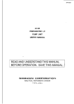
}ISPLAY
ICONS
eight. airfields,
glider sites. microlight
sites, parachute and parascending sites,
When showing screen
beacons, helipads,
towns and user waypoints are represented by
are
different symbols or icons. These
lllustrated below.
NAVIGATION
In order to navigate along pre planned
routes. SklmaprY - and TrackerrM have
facilities to a1lo'" ),ou to program up to
250 user \+a)-points. then using these
ua1-poinls plus the enormous built-in
daiabase. pian up to 20 routes, each
conta:.:::g a s:art point and up to 20
turn:.9 :Oints.
There :s a-so a simple GOT0 navigation mode
which a- -c".s ]-su to f 1y f rom your present
posi::c:. dlrectil- to any point in
or the user waypoint librar5:.
the
database
All rz.r-points and routes are
normally
prog:armed on ihe ground and stored in the
wa1-po::: and roure B{\K or librar.v.
Wal'polr.is are specif ic locations, an;'where
in the ro:ld. deflned by a name (up to nine
AIRFIELDS
le: te:s or
longi:ude -
numbers )
, a
Lat
itude
In Skyaapfr and Trackerl'M, waypoints
tuo func t ions
HELIPADS
and
serve
.
Firstly thel- can be used to build routes
for conventional wal'point navigation and to
add personalised points to t'our map.
Secondly, ii : -i -ng ou:s:de the iimit of
the built in iia:aaase. :ie unit will use
the waypoints 1-ou har-e pr'0{rammed to create
the map.
For ins tance .
:
USER WAYPOINTS
GLIDER SITES
MICROLIGHT SITES
PARACHTJ-TE
Screen icons
i:
SITES
g:-ng on holiday
:
io the h'est -:tf l;'i ng . prog ia:. t
-an to do some
-:: -e1ds. beacons,
:a: find on the
:-an to visit, as
:
-
lowns and iand-a: .(
chart within tra a --c
wa-vpoints.
*hen you use:ie u;:i: ,i the specified
area, al I your *a]'Jo:.nts u i ^ i be shown on
screen in the sa:e hal- tire built in data is
normally displaled. The on11 thing missing
'"i11 be the coas: line.
-i .r?; 001 ^s
STORI},IG WAYPOINTS
To begin storiti ;al'points, enter BANK mode
via SET UP frc: screens one, two or three.
Screen fourteer- '"ii1 be displayed.
HETUHI{
i'ii
shorn'ing and the LP kel 1S
h'PT r-,i2 v.ill be displayed, if the
DO''r\ ke_r,- is touched, WPT 250 wi I I be
:ou::ed.
drsp-a1ed etc.
ii ::e EDIT key is touched, screen sixteen
i.. be displayed r'' th the word NAYE
r.
higrl ighted.
5EI
SETI,P YEHU.
EXIT EI)IT MODE, BETUBH TD WPI§.
WPru
UP
vlEW AHO EDIT $/AYP]INT§.
tYPTr
WPTS
LAT
VIEW AHI) EDIT HDIITES
DDle3.15
5:-EDT ITEIT DH
lJ{t]DE
Sklmap screen fourteen.
UP
8.1 S5E HASTINES
PDSIIIDN
lllAP
ED DIHEDTLY TD IIÅP UDDE.
l{
LDNE
HTE
DD,l
AIYAYPDINT
N 51eD.B4
ENTEH OATA.
DilII'N
5EI
S:.jr:ap SCreen sixteen.
. The dispia;' will
-s node ai.ou's 1,ou
=:-- U: :O 250
A:I']TåTIC WAYPOINT CAPTLIRE.
. : :.:= ka)'poi nt lrcu naoe setected was empt;i,
r -.:.
loth Lat and Long set to 0), and the
j ias a f ir. the present position r*,i.11
be '".:- tten automaticall;.' to the LAT anC
-lli!:1e-'is anri tire time ",iii be i.'rirten itr
:te ),-:j'iE :,:rd iSkl,map|v onl1 ).
h,ith
^racke: ". :ra:ause time is not alr.a;,s knor.n,n.
ihe nai:: : -t -: r i i l have the wa1'point
number u: ::': r-.
G?
q:-ffi{
Uril 3r\r
TD
trI
HEXII
BANl(
FFt
frAlr:
UP
AWAYPOI{T
LA- t{ 5.?0.84
!Dt{3
DHE3.45
r
F-;
ECIT
E.{
I f you r'an:
:: . :e the present position
as a u'a1'po-r- -. -:: -r touch the SET ke)'.
This r*'i 1l - r- - :r? ::esent position in the
-
SSE HA§TINE§
DI]Wl*l
_
T'-S UAvpDilT.
EI]IT
edit the
descri be'i
:r.-'räp SC:een fifteen.
l-s
:- fiiteen shows the first of the user
r^ith
-::s
the
wal,polnt
has not been previousl-r,
"aypoint
\{YE field will be blank and the
LONG fields fu11 of zeros wi th
of N and E.
.".': - I0\
'lllltrrr
field is calculated based on
=:d LONG of the waypoint. Il the
--',\G are al] zeros, the POSITI0\
.. Tead OLTSIDE DATABASE.
tii)iilll,ri,rtlr,]
':
:
i
:-:
-:i:
D0h'N
keys can now be used to
t or previous waypoint.
a=
ing ::;
move t h:
to edii
: -iia-:on. You may then
t:c. :s ing the technique
a:d
-'... :
'_'=
r.e)'S. )-ou may nor4'
).:l''-:. LAT and LONC
l.-,..'
- Jr -hri-,
,l s e:. L a\'3
i
nrrmber
-etted.
u
..:,-
ter is
and
the
1'
wi 1 I then
\ keys can
a1
highliE::=1.
first i :-:
hig. -.-
be
-
now be u-=-,:
If it -r- :
Aand digit -s
or Loi.:
9. Tit
i f 5.'ou :
::.a:ac:er oi the
NAYE
::l',' f1316Cter between
. -: :he highlighted
then
:j-.:-c iieid (i.e. Lat
" :: sei beirneen 0 and
. :ejs'*ri1 auto repeat
:ia: ,:r: iherc.
-
IJ
1as t two digits in the Lat and Long
flelds, to the right of the decimal point,
are one h:ndredths of a minute.
The
BUILDING
A
,Jnce each character has been selected,
touch the SET key. The cursor will then
move on to the nert chai'ac:ei of the chosen
lield.
fieid has
When the Iast characte: '::he
go
io
the next
been set, the cursor "--,
--ie
last
character
f
ro:
line heading, i.e.
of the LAI'field to:i:e;oi'd L0\G. h'hen
the last character of::. -0\G field has
het:n entered. the u:_: ;--r revert to
sc
ROUTE
.::': screen iourteen i f the PiL-iE
: - uci:ed . t he uni t will dis:iay
q:.J1II
A 3D
the
the
D
EFEHiJ TLUNDPA
Ir'ht:n ),ou are sat is f icd the waypoint is
r:orrect 11' set. touch the WPTS kel'-. lhe
d i sp l ay r" i l l revert to screen fi ftee:.
repeated f or e:-': -. :
l oI lhi' ];0 waypoints. When fi:-:-=:
lorrch Lht' UÅ\K ke-v to revert to s::::{'ou r Ieen. ihe main BANK screen.
NOTE. If the waypoint you t -s:- ::
used as part of a rou-.a. ",:,rtot
al
l owed to ed i t that uai':': - : :
be
'*iii
untll ii has been removed from the ::,,::
'ih is is a safet)' f eature to P::-- *1:
to er,s:-:s
run i n tent r'ona l
al terat ions
.1
5EI
-. s:own wi th the r
adjus
=: lris can be and
:'. -islrg the UP
-
--::
,-::
a)
z'-
r-
-
::::
-
I
Z
Lai': - --_::
t is being
.
Y
The obje:L of the ror:te iunction is
allou' 1'ou to set up to 20 routes, each ra star: point ard up to 20 turning poi:
(TPsl. lhese rcutes can be called up
f 1o'^i ,: l.å\' node. The turning points
be c::s=: :.o: ::. :ui1t in database, whis s;::----lej z:.: a:ranged alphabetica: irom vour user defi
PLIjASII
rutr t cs
HSIIffIYX
DDIIl.l
\Tlap screen seventeen
hhi tsl acLually editing the way''point name
r)r coorrjinaLes, the top key will change to
irackspace ( ... ) .
L se this to move the
-rii'si)r' to titc ie,,.
er-i,
UP
SELECT ITEU 0B ENIEH DATli.
coorrl i nates.
al
THIS TP: STAfrI
!iAME: hlÅJ{§T0H
LAT: H El20,B1
LDHB: tY DDie3,l5
i"cca lr:ulated and updated. -'se this to
t'r i 1"r the 6's1,point ente:ed i s where you
rocedu i-e ma), be
[nl
BANK
DÅTABASE: FIELDS
r
p
TD UAIH BANT HENU,
F0IJTE:
-\s t hr' last character^ i':' ::e -ll or LONG is
('nttretl. lhe POSITi,-,.' :'-e-d will . be
'l'lr i s
SCT
S:i el:een.
r('en I i f teen.
irlt'niled it to be. :a :,:,:. rePeat
procedure io correct
erl i t i nq
key
-?i--li
a t
:
--:
:.: f-t:-
--Ec----<
-=:--:
-'i:e number has b
s:,:u1d be touched.
:--S TP legend v
-i-:
:: . choose ST
:,:: 1ou intend
;:a:red in nume
Now touch the SET ke)' to move the cursor
down opposite the DåTABASE Iegend. This
is the database field and can be selected
between FIELDS . \;ORS. \DBS, TOhNS, WPTS.
HELIPADS
keys.
II
Choose
or
CLLAR
using the Lp and D0h\
the database from which you want to
select your stari point or CLEAR if you
want to blank out an existing turning point
(see across the page). Let us assume we
want to f1y fron Yanston to user waypoint
No. 125 via DE*I \'0R.
the UP or DOh\ keys to select FIELDS,
then touch the SE-t key. A list of
countries will be dispiayed in the middle
of the screen. Lse the L? and DOWN keys to
select UK, then touch SET. If you have
selected English airfield names on the i"lAp
DISP page, an alphabet list will now appear
at the bottom of the screen with a pointer
under the letter A.
Use
use the LP or DOt*\ ke1.'s to move the
pointer along the alpi:aret until it is
under the ietter !1. -ouc:: rhe SET ke;-.
l\ow
Å-i sames - in tne LIl FIELDS database
ttairi@- ui tir -y caa noh be scrol led
throogh using the L? or D0t\ keys. In
order to alior- quick access. the Up and
Dft\ ke1.-s rill auto repeat if you hold 1,our
finger on thea.
hhen you have found YANSTON, touch the
ke5i to select the item.
SET
If
you selected airfield names in ICA0 CODE
on the IAP DISP page, instead of selecting
the ai rf ield b;.- name you wi I I be given the
first two letters of the ICAO code (EG for
the UK) and -vou v,i 11 have to f i Ii in the
other two letters. So to choose Manston
from the database, you would select EGYH.
0nce an airfield has been selected asa
turning point in a route, you will be show
the airfield information page and be asked
to confirm your selection.
\ow the START point has been selected , the
cursor will go back to the THIS Tp: field
hhen DET
is
showing, touch SET and select
TPO2.
This time select hPTS database and find trlPT
125 using the L-P or D0WN keys. Note: WPTS
are found numerically not alphabetically.
hhen WPT 125 is showir,g, touch SET.
This process can be used to select a start
point and up to 20 turning points in each
of 20 routes.
rill notice that as each turning point
is selected, the individual 1eg distance
and the total route distance is displayed
at the bottom of the screen.
You
Touching the BANK key will revert the
display to screen fourteen. You are nou
fully
programmed
along your route.
and ready to
navigate
EDITII\re OR CLEARING AN EXISTING ROT]TE.
If a route has been previously programmed,
it nay be edited or overwritten using the
technique just described. Simply select
the TP to be altered and ailocate a new
position to it.
i f you want to overwri te a long route (-say
15 turning points) with a shorter route
(say 5 turning points), ihe unwanted TPs
from the existing route must be cleared
down by selecting each unwanted TP in turn
followed by the CLE{R option opposite the
DATABASE
legend.
REVEITSING AN
HISTITIIG
ROUTE.
If a route has been previously programmed,
it may be reversed to accommodate a return
j ou rney .
Select the desired route and torrch SET.
the THIS TP legend
will then be highlighted. The UP and D0WN
keys can noh'be used to select the rr,ord
The word START beside
RVSE.
0nce RVSE is shoriing, touch SET and the
waypoints uithin the selected route witl /- reverse in order.
to allow the next turning point to be
selected. Using the Up or DOWN keys,
select TP01 and touch
SET.
This time select the VORS database, sel.e-ct
D then find DET using the technique .iust
&scribed.
15
7-
After touching
FLYING A ROUTE
In order to flf'- a1ong one oi the twenty
preset routes. your unit mus: :irst have a
valid position li.x (or be l: L-r10 mode).
BouTEr
MAP
ffi I
LEE: STAHT
MAN§TDN
sot:
)
TPCI
:: the rou:e, in this ca:'
:.:.:
be
START.
c:osen to fly to s:, .P06, the
assune you wantei :: start at
i :o
TPO6.
:: :- --:es belor*'ROuTE a:- -:,: si-.oh the
,-- ..=-=:'.:' :he TPs and t:= : : i: -;.g ( BRG
)
.-.., t: .i-:
F-r.G
r Detween tl::
'. - ,-s l:ed route
=
-: .- . - ..l: :he !L\P
-
UP
-)'
} SDIJTHEhD
headi:g'"i11
Touch SET again and using the -? or D0wNkeis. seiecl START > TP01 mean,:i lhat you
'* -s: :o f l1 to TPC)1 . The unii :>sumes you
a:. s:arting ii'om the prer'- -,rs turning
To commence f11'1ng aio:g a :ouie, seiect
the NAV screen b1 touch-:-: ::e \A\-pane1 on
screen nine.
RETUHH TD MAP,
SET, the LEG
highl ighted.
rave been
return to
a--tpn
Dt]Wt.t
BHE 3DOT HHE 2B
i\!
SELECT |TEM DH ENTER DAIA.
ETE
3,8
!:DI
5ET
Sk;'map screen eighteen.
SCreeil , iui Lr
rjR e i ghiecn . . lie mar n
"A\
l"ield
numeric
R0U'fE
be d isplayed wi tli the
,rc re
higlrl ighted.
'l'he L.P and DO'*\ keys are used to scroll the
ROL'l'li betr*een r-r0 and 20 in order to cnoose
fht: rlesired route. tf 00 is selected. n0
routt' is ii, Je llown and NAV mode is r': f '
Rou tp rlr-r * - ^ I alrr'ays be selected whei ine
un il i s : i;-st switched on and shou,d be
,el: al
t-,r-1
if
G0T0 mode
is required.
,'.r.:r -,r,c ,lesired R0UTE has been selec:ed'
::r S:l ke1' shouid be touched. The cu:sor
", i :oh move on to the words LEG.
\ou tra1' noh' use the L.P and DOWN kels :o
more between the words LEG, ROUTE apd 'l--'-0'
G0TL], i s covered in the next secrion.
lhe ohr;ecr 1s to select a route num0€:.
...--. -olr,-+ +he leg wi"hin that route iou
':'ncr have to stari ?-;-sh lct fr;.-'-' route but ca:::e beginning of the u
:
r
ck up
any,r,vhere
along i t
.
wish to f 1y route 0l f t'{r,.^
:., finish.
You would first select
'.,*apos i te the ROLTE heading.
I
:u:rent fix,
f tr.:
notir=
to
::"=
rou:
a
tur:-:.
I
-:rned together bY a
:
ine.
,-l
ti---
It
po
1n:
+ho
:.ssume you
j
;
Up
16
.
::e destination
bY a f-ine to
=::;j
ias situated when
o: - s shown above
:-.?. ,<:al:.:g ai the toP Of
: :,; , e l: :ai:d s I de , the RNG,
rce to ru:t ro :ne destination
l:o: 1-our Present Position.
ne units seLecied during set
-
t rn:
-::-
"
a
--
w111
: start and destination
:: shown on screen with
The :-
lhe
You
1:-r,ll has now been added
. ..'ou to fIy along Your
:u:ning point
r- - :-: : ::a:
-
In the cel::. - : ::.: : l:ee: a: :i:e :OP. ti:e
BRG Or mag:-=: - ==:-. 1 : S--8er taSSUming
: :--:-, is shown.
no wind) tt, -:.:
ide the E:., . ::..:-E:-L is the ETE or
This is the
Estimated . -:: -:.:,:u:e.
rours and minutes, it
estimated i-:.
::e dest ination turning
will take tc :::
point from .:-: : .se:: position at the
Bes
.
"
present sf,ee:
C,OTO MODE
F:o: screen eighteen if G0T0 is selected,
:ie active route will automatically be set
to rrir and screen twent;.'- r, i t1 be displayed.
.
HEIUHH TD MAP.
At the bottom o! . - s::ee: o: ihe left is
the ETA (Ski'na;-' -: -i ' . Tais is the
estimated time :: ::: -'.'a- a: lhe turning
point. Ensure you have set the local time
of fset correctly t3 get :.::rect E'TAs. See
§FI FNT BNTD DESTINÅTIDN
LDNB E DD1E3.{5
is Gc. This is i lte actual
ground speed oi the aircrait and is
displayed ln iinots 1f map units are set to
nautical mi1es. yPfi if map units are set to
statute miles or rPH if the map units are
set to kiloi:e-Lres.
Bes
i,le
TRK
tc lour ASI to estimate head
or tai lwi nil corponent
If ground Sf,?:l is less than 0.5 Kts, the
ETA, ETE. -F.:. a-,i GS fields will be blanr
and the ma;, ; - - - revert to north up i i'
track up is s= =. -t'j.
Compare the CS
.
To exit NA\ 'i0D: :.: -:= the fu11 route has
been flornn. se..-: sl::::. eighteen (\A\-1.
select ROLI: tl r;. ::..:. :,,t::'ltP kel'.
DDWN
ÄEEt]EFEHIJKLMNUPUHTi I UYWXI I.
5EI
SILEDT ITEI' DR ENTEH OATA.
TrackerrM does not E-r'e an ETå because real
t ime is not aIwaS's n:.i,\.n.
estlmate cioss r.ind c.:::'a:a::.
UP
It{AN§TDN
il EIED.DD
page 11.
In the centre of the s,::een at the bottom
is TRK. This is the ai:ua1 magnetic track
the aircraft is travel- -:{ over the ground'
Compare this to )'ou::a::.etic heading to
MÅP
Sklnap screen twentY.
Sc:eer twenty a11ows )'ou Io
f
f
:':: :'our current
ii:n an;. database.
pos i
t
f 1-v di
rect
ion to an]'
pr-r
11
irll
nust first sclect iire iatabase. then
the rtem lrom the database. jr ile samr: rnal'
as items Lere selected uher :u- ld:rq a
You
routt:.
When enier-:.: saree:l trr'ent1', lht tri'-ri[]
-: : eil ighted and ca: be
FIELDS ri,,
.-.: .
changed to
'DBS. TOh'NS ' hPTS or
r-.P or DO!{N kel's
-.
',,rs
b1
-:HELIPADS
.
database '-'= L-rr.a.-. --st r'ilI noh appear
:ne screen wilh a
along i:.- :,',::o:
pointer - ,j:: ',ir :. .:r'slarl letter ma)'
,*-,1 l) SII'I'. l'he
then b" ..,-1i.-grl
destina-- - :al' ni,n t'- si-'-ec-Led from lhe
chosen I r - .-- a.ce \. - ::l -: - ,' and DOh'N kel's '
The Lr. :.t -o\c .-...,s "ilL update
automa: - a- -:. as the da:a:ase is scrolled
throug: ..: i'our i-eferei.ce.
6nCe -_1,: :=S-:ed deStiia:-i,i: haS been
found. --,-',- Sal to acirra:e GOTO mode.
Scree: :--:.::.r:. *il1 be dispialed r,'ith all
the'i1'. -:.,:-a:ion as detalied in the
: si'c:ion.
FL\l)'i:
To er'1,-D: before the fu11 leg has
screen elghteen (NAV)
s:-ec:
been '
,,,fF.
Touch SET then YAP
l,-,'
s=
then
l
e
:aer
sht
re:u
to
-c.
-
-
.
t7
a new turning point has been selected
or the \AV / GOTO mode cancelled. :te label
on the top key will revert to !G.t; ){E\1.
Once
APPROACHING
A TI'RNING POIhIT
i ro new turnlng point is selec:ed and the
:,::1ng point is passed, t:e warning
::-rsaqe at the top of the screer "ill read:
In either \AV or
C0T0 r,-,,je. -v'nen the ETE
d rops to
trr'o minu+-es ..: :r.os. an extra
message wi 1l be prin-ied ai:oss the top of
the screen
HNE B.B
->l'J:Iffi
H_
8BE lDB
ETE D:12
----r- 't!{EEl
ä'lt
OU;IIT
:|e$-E;l
.
+._.\\_\\
r=..
EfilEJal lTnklosl / res fi{
l- 0 Hm JlP0§: 3.7 §TTtltTEHB,f
reen tu'enty,'
ZEUT{
IN
'-q:r.E
Skymap sc
NEXT
LEE
ZNt]lt,|
DUI
INFt]
one
I f, .vou are in l'irii' mode, the label t)tr the
lop key wjll ch;rngle to NLiXI' LEG. If you
are in G0T0 mode, the label will change to
NAV OFF.
If the unit is in G0T0 mode, touchi:< :he
Iop ke1 ui]: re\ert the unit to norma- .'!1P
mode i, i thou: an) \ÅV inlormaLion dis;- a1 ed
and the GO.0 iunct ion turned off.
{f the unit is in NAV mode, i.e. fi1 :g a
route. touching the top key w111 retui'i. iire
un i i io screen nineteen r,'ith the :ert
turning point in the current route aci-r-e.
al I the \AV information updated for the :er,'
destination turning point, and the M\lll.:liT
message gone.
I f 1 ou do not want to cont inue wi th : he
route, touch INFO followed by NAV and -':om
screen eighteen, select CLBRENT R0LTE tr, lr0
thus cancelling
NAV mode.
ri the turn:1ng point just reached was
las t one in the route, the message at
top of the screen will read:
LiST h'PT IIIYINENT: HIT NAV OFF
and the top key will be labelled NAV OFF.
\ciu should acknowledge the end of the rou,.
has been reached bf, touching NA\/ 0FF.
1B
,
--J.'
.\C ?OI\I
PÅSSED: SELECT
\TTT
LEG
i,I sirow the heading tack to the
-::.-:g point, DIST will show .Cistance back
: : ::e :urning point , the ET.å and ETE wil l
-::,:; a rer-ised arrival time a: the turning
*
:
and time
;ust
:e
to run back:.1:he turning
passed.
PASSED :essage will stay
until either a :e'i turning pOint
selected or \AV or C{,I0 modes are
ce11ed. or the unit is s'*l:ched off
TLR\ING POINT
screen
.
0:ce:he last digit of the longitude has
:eei. entered, .le cursor will move down to
DEI.{O MODE
GF.,]
'.D
SPEED.
Touc: SET then enter the ground speed
1''ou
From screens t-rle, tr+'o or three it is
possible to se -ec: DEY0 Y0DE. If selected,
the displa;' r- - allow the full use of MAP
'".sh :o run the demo at (FAST or SL0h')
Fasi is 720 knots, slor* is 144 knots.
user
DEiIO YODE.
YODE
but wit: s-:ulated data, based on a
entered s:a:. position and ground
speed.
All functions vrl- be exactly the same as
for live data bu: the words DEMO M0DE in
big Ietters wi I I be shown across the
screens and al 1 bearings will be true, not
magne t
ic
.
is
entered screen twenty two
be shown with the words DEM0
highl ighted .
When DEM0
t-
If )-ou are ready to run the demo, touch
SET. The cursor wiii move to the right.
Lse ::le UP or DOWN keys to toggle demo mode
0\ o: OFF.
T0
Sklurap sc reen tr.'enty two
select 0N and touch
until
unit *i1I flf'
presi-i
NAV or
exit
to
the
des t
inat
ti:e curs,t:
ion at
the
speed.
DEllO :10D8.
DEYO. then
return to ihr:ain menu,
toggle DE!10 YODE -io the
i1 ternatively,
OFF posi: ioi.
unit of f iher: :".'.. on again.
.
move
SET.
set up as per the position entered in
select
5ET
along side the LAT and LONG legends. å
default ground speed of SLOW (144 knots'
will also be displayed. If you do not r*'ani
the demo to start at this position or rur
slow1y, you can change it.
to
demo mode.
turning point has been
en:e:rd in either \AV or G0T0 modes. tht'
The last kno,*r position will be displa;'ed
Use the UP or DOh\ keys
to the LAT legend.
rui
The unit will immediately jump to yAP y0DE
and dlsplay screen eight with the position
To
§ELEDT ITEU DH ENTEH OAIA.
up to
Once a. destination
$!{t{
r.,'ff
move back
The-ap uill noh'sit still
GOI[, :,rde is entered.
UP
LAT: H 5'lEl.DD
LENE: W 00e3.15
set, the cursor will
scree: tventy two.
}JENI.J
I]EHD MDDE: DFF
i
MODE
l.{AIt.J
HETURH Tt) UAIH IJIEHU,
EEDUi{t} SPEE i: :
will
0nce
.
sr.ilcn
the
will alral's be off on power up
and should never be used in the air for
DEMO MODE
safety reasons.
with the antenna
(Tracker'r'M)
,-.:
data
exte:ral
--' the un i i delects
incoming
be
satell i :e ,lata. DE"10 !10D8 wi ll
automatrca- -: disabled for safety reasons.
DEMO
yODE -c:.u:,.r-d be used
(Skymapl'Y,
detached .
SET. The highlight will mor-e :o :re
right. Er:ie r the latitude of the po;n: 1'ou
wish to start the demo running iror usinq
the same technique detailed for inout iing
Touch
waypoints.
h'hen:he last digit of the L{T has
been
entered. the cursor will move dor*n to LO\G.
Touci S:T and enter the longitude of )-our
:er'-s:: starting point.
19
4.
STANDARD AREA CO\IEMGE:
Austria. Belgium, Denmark, Finlald. France,
TECHNICAL
German;.'. Greece, Hungary, Irelatd. Italy,
Ya1ta. \etherlands, Norway, por:-{aJ-,
Soain. Sr.'eden. Swi tzerland , L . i. and
\ ugos l avia.
SPECIFICATION
Trackerfr only.
DåTA i\?LT REQUIRED:
DIr,,lEN§l!N§
MAIN UNIT
I ?g::
I 5ir:
; t i',:
Lnit front:
[.nit back:
Or'erall depth:
IronI
h
.:
AJJ
i 6::
i t-}nn
depth:
llack dept
r
r :6nnt
;
ibr.rth including bat:er;es
-
Llr,:ttl
r
PORTABI,E ANTENNA
^G,
-5.
BATTMY LIFE:
- i::s ni-cad 4 Hrs Lj:::-: iassuming
in::::_::ent use)
CO!{PATIBILITY:
Sx1-f orce SkymaprM.
[,ength:
Diameter:
I'r,ight:
25mm
0.05
I;in height:
RECEIVJJi:. SENSITIVJ IY
)
1-:
" .: irsproved by the CAA for ,-ght
aircra:: .-adio class 3. Number L{301i,31.
- 166dBh' minimum
SATELLITES TRACKED:
Up
to eight sitrui:aneously.
ACQUISITION TI!{ES:
15 seco:ds hal-: a-
I data known) .
2 minu::s col,j .:_s-tion, time & almanac
known. ::":e-e:.-.,:-.;nown)
7 minu:rs au:i - _:a:^on (almanac known,
positro: & :-:3 ;-.--or.'n).
15 minu:es s::::: ::e sky (no data known).
.
POSITION ACf,.R{Tl
tsoth Sky:napfr and Trackerfr
Availabil::i
DISPLAY TYPE:
ll,. r i28 pixel blacklwhite compensat.:g
'.
- -; supertwist with cold cathode
i'uorescent backlight.
DISPLAY UPDATE RATE:
i')' 2 seconds (sub.iect to data
a.iailabr'lity).
POhER SUPPLY:
-!'' - 30V external DC with internal
: a: ieries fo emergency use.
):
2
r-t
+
50"C
.
+60"C.
-eters with Selective
::.
VELOCITY ÅCCTR{[-:;
0.2n/s
(0. -:-1 1:::s ' RYS steady state
(subject to S :.
DYNAMICS:
1000 knots
ve.oc-:;-. :'i
4.8 Watts.
BATTMY LIFE:
:y-eamics.
ffif{§LtlPT]tlr\ :
1.25 Hrs ni-cad. ,ass'::---: -inimum
brightness and i:::e=-::::: use).
DATA OUTPUT:
N}IEA 0183 data
forua:. :": Sil iorce
format (automaticaill, se-e::ed)
PC data
.
PC INTERFACE:
PC upload/download
TEYPtrRATL]RE RANGE:
to
to
:
15 meters F-{*c - - -
MAXIMUM POI{ER
It''e
:
.
lE_cllfrc.\r
0"C
-aqe: -20.C
-,- & GpSSS,
§lymap}'i on1y.
0.23Kg.
rlax a ir speed: Subsonic
(st ructur-a. :ating for antenna)
:
-. -
Kg
120mm
Irin rn'eight:
-re:a t i ng
Garmil
lrimble TransPakII. TNL :_,-:- - :ii00 &
i.ightmate Pro. Yagellar t"åi'-r- 00+. NAVs000
& SK1\AV5000 and any ot:er- :rand of GPS,
DECCA or LOR{\ with conpatji^e output.
interface cable and
ral-point/route planning map software
available.
724nm
DXThRNAL FIN A].J]'dNNA
( op t i ona I , Sk;,mi..o'r'M on15,
'-
.
PC INTffiFACE:
PC upload/download
(SklmaprY only)
5k1mal
t'
: - -
--nimum brightness and
iic reen ;
i l5n: r
'l'r'ar:ker I'l u'e i ght ' r: i io
Sk.rnaprY r''eight:
1.1§9.
CAA APi'RO\
:'-{Ai. 4183 f ,:800 baud) or AR\.i, !,-30 (RS232
:: FSi22 9600 baud ) .
}T{XII{LY POhER CONSTMPTION:
in:e::ace cable and
waypoint/route plannirg :al softr.r'are
available.
ELECTRICAL COI\NECTiON
APPENDIX A.
Data is presented across pins 1 and 2 of
the : way D type connector located on the
rea: of the unit.
SKYMAP1Y DATA OL'TPLIT
wili output two sentences every two
seconds whils: in !L{P mode with a fix in
the \ational lla.ine Electronics
Pin 1 is TX+ and pin 2 is TX-.
Sk;maprM
shouid be used as follows.
Associaticn's \-1E{ 0183 ASCII format.
connect pin 2
or data input
This output is intended for use with
equipment such as data loggers.
The first sentence is the Recommended
Minimum Specific GPS/Transit Data (RMC)
sentence.
The second sentence is
Positioning System Fix Data
the
Global
(GGA) sentence.
The sentence protocol is B data bits, one
stop bit and no parity. Baud rate is 4800.
0utput is electrically equivalent to
RS422.
.<;>.
<B> . <9>
f connecting to an I\YEA input device,
of the SkymaprM to the Rx data
line of the receiving device.
Coni:ect pin 5 (ground ) of the Sk5'maprM to
the data ground input line of the receiving
der-ice.
If connecting to an RS232 input device such
as a personal computer, connect pin 2 of
the Skl,map''' to the RXD (data input ) line of
the receiving device.
Conrect pin
grou:d line
I of the SkymaprY to the
of the receiving device.
data
If connected in this vay, the ground
of the Skymap'ru and the ground of the
NOTE:
The sentence structures are as follows:
SGPFJC, < 1>. <> . <3' .<.1 > . <5>. <€>
. - - >. < i i>*hh<CR><I_ir
I
These
receiving device
.
MUST BE ISOIÅTED
from
one
another.
.
of posiiion f ix.hhrnmss format.
Status, A= \'alid position, V=warning
Latitude. ddmm.mrm format.
Latitude hemisphere, N or S.
Longitude. dddmm.mmm format.
<1> L'TC time
<2>
<3>
<4>
<5>
<6>
<7>
Longitude hemisphere, E or
MM,IORY
W.
Speed over ground (000.0-999.9 knots).
<B> Course over ground ( 000 . 0-359 . 9 true ) .
<9> Date of fix ddmmyy format.
<10> Yagnetic variation 000.0-180.0".
<11> Variation direction E or W.
,<l> ,<2>, <3>, <4>, <5>, <6>, <7>. <B>. <9>
*hh<cR><LF>
, M, < 10>,y, .
SGPGGA
<1> L-TC time of position fix, hhmmss.
<2> Latitude. ddmm.mmm format.
<3> Latitude hemisphere, N or S.
<4> LongiLude dddmm.mmm format.
<5> Longitude hemisphere, E or 1,.
<6> GPS quality. 0 = no f ir, I = li.'; gcod.
<7> Number of sats in use. 0r:t to 08
<B> Horizontal DOP, 01.0 to 99.0.
<9> Antenna height above YSL (metres).
<10> Geoidal height in metres.
.
is followed b5,a checksum
*hh), carriage return (CR) and a line feed
_t).
3ach sentence
CLEARING DObN
0n both Sk5':a:r' and Tracker'r'M it is
possible to ,r-:iate a memory clear routine
that uiII :'r-äse all user waypoints and
routes an,l :.ser all r'ariables to default
values.
To ini i -. - - the memor), clear routine,
switch ir: ::i t off. cover al1 four keys
simultar; -:,..' b1 1a5,ing one f inger down
the rigi:: . ,je of the screen, then swj tch
on and ..--'.e )-our finger.
The un-- ;,--
ask you to confirm memory
clear :i, r: during which time you may
bl"touching the N0 key.
change i.'i::r:d
If y'ou i-::,:: tr'ice by touching the YES
key, al - ,-rs:: def ined data will be lost and
all r'a:-a: -es u'i11 be reset to default
values.
21
In order to achieve any sort of accuracy
frou this technique it would norrally be
necessary to have an extremely accurate
atooic clock built into the receiver. This
r*ould cost tens of thousands of pounds and
is just not viable.
APPENDIX B.
WHAT
IS GPS?
GPS (GlobaI Positioning S-v-stem) is the
American Department of Defense navigation
programme that has been designed to take
the place of the existing Transit satellite
To ra}e the systen work accurately on only
reasonably accurate and therefor: Iow cost
clocks. tro very important techniques are
sys tem
The
ll Code ntchinl or svnchronization- Each
satellite transrits, for civilian use, a
unique 1023 bit code. This code is repeated
€:rery tillisecond (one thousandth of a
miies).
second)
n addition to the 2l active satellites
there are three spare satellites that may
be quickly manoeuvred into place in the
event of the failure of one of the active
In the receiver, circuitr-r- generates an
identical code that. is then slid back and
forth in tire until it ratches the code
.
full system is based on a constellation
of 2I active satellites orbiting the earth
at a very high altitude (t-v:pically 11,000
I
uni ts
-
HOW DOES
-
beint received from the satellite.
is achieved, the time
at vhich the receiver is generating the
start bit of the code is recorded. The
d/fferencr: in time (or offset) between the
receivel generatii:9 rhr-' cocle and the
sateLLite generating the code is therefore
measurable because the time at which the
Lten a perfect match
IT
hORK?
iri a very carefui
circles the t-arth
'iach satelli t-e i1, pl36g:l
orbit such thai it
covering the s36r path every twelve htlurs.
The orbits are arranged in such a rr'ay that
at any point in time, from any point on the
globe, at least four sateLlites will
be
vis ible.
The technique for actually establishing
position from these satellites is one of
simple ranging. ie position is calculated
from distance measurements to
satellite.
each
positiort of each satellite at any
given time is known. This informaiion is
The exact
åctually transmit ted by each satellite
respect to universaL time) that each
satellite starts to transmit its coded
signal is also known.
everlr few minutes. The exact time (vith
Given this information and the speed of
radio \r'aves through space, we can establish
our exact distance from each satellite by
simple mathematics. For example, if a car
leaves point A at exactly 1 o'clock and
travels at sixty miles an hour to point B
r.hich it reaches at exactly 2 o'clock, r-e
know the distance between points A and B
must be sixty miles.
22
used.
satellite
should have generated the code is
known.
This gives a very accurate way of measuring
the tire differences between transmission
and reception of the signals generated by
the satellites, but does not help with the
need for an absolute time reference (bear
in nind -that if the clock in the receiver
were only f00 rilliseconds (one tenth of a
second) out vit"h respect to universal time,
the calculated distance from the satellite
would have an error of 1,860 miles).
This probler is
osercome
bY
a
second
technique.
of ar ertra sateliite. In
order to obtain a positional fix in three
dimensional space, it is necessary to know
the exact distance to each of three
satellites. The exact distance is however
not known because of the presence of an
offset or error in the receiver's clock
with respect to universal tire2l
Making use
A fix is nevertheless calculated using the
three satellites, all be it erroneous.
this fix is calculated, a second fix
is calculated using satellites 2 and 3 in
conjunction r.'ith a forth satellite. This
is iepeated for satellites 3, 4 and I then
-i. 1 and 2. This gives four calculated
points in space.
I f the four calculated points do not
or-erlap, - there must be a timing error
0nce
present.
A slight correction is then fed into the
receiver's clock and the Points aie
caiculated again. They move closer to each
other.
This process is repeated until al-1 the
calculations tie up correctly at the same
point.
The exact Position in three
äi*ensional space is then known and the
offset in the clock eliminated.
Similarll', a two dimensional fix can be
signal a."ai lable to civillan irsers is
transmitted lrn ',.57542 GHz t-inl-v and is
cai 1ed the C1A cotje . l/A stands f or rloarse
The
Acquis i t ion.
This code is relativel-v s imple compareti Lo
the P code and has a repeiition rate of oti'.
millisecond.
The present maximum accurac;'for receivers
using the C/A r:ode is l5 meters.
There is the possibility howevel ofl l his
being intentionally degraded ( by feeding
random errors into the satellite c1o'-:ks) to
100 meters for strategic reasons. Thi5 i5
called Selectirre Availabi iit;' or S/A an.i i s
implemented at will bY the D.0'D.
to day accuracy ls monitorec by F'alcon
Air Force Base, Colorado. r,iro :-eleive
information frcm a group of ground staijons
positioned at Ascension Islancl, Diego
Da1
established from three satell-ites.
Garcia, Kwagale and liawaii'
ås a result of this technique the receiver
rloes not need to knor^'absoluti'universal
These stations receive ihe satelli tt:
--= :litlalir . al I iha: is ne :ded is a
:::s::af 11- staL I ., . iock for takir'i -elati-"e
measurements ote.'short periods betxeen the
signals received from each satelllte.
-,
{ rough knowledge of universal time is
needed in order to know which satellite to
expect in which part of the sky, this is
usually given by the first satellite
acquired after switch on.
The exact universal time is transmitted as
part of the almanac and health status data
Ly each satellite. This is then corrected
b1'the receiver for signal transition delay
as part of the position fix calculations'
ACCURACY AND
RELIABILITY.
GPS sateltites transmit two separate
pseudo- random codes on two di fferent
All
frequencres.
is the P code which is
transmitted at both 1.2276 CHz (1.2276
thousand million cycles per second) and
The most accurate
1.57542 GHz.
I:e P code is extremely complex and has a
::petition rate of one week. This code is
::s:ricted to military use on1y, is capable
- - supreme accuracy and is supposedly
i irem lor iming äccuräc-r
are ieit cied ' :l'i^o.'
errors
an.v
Ii
infl, t:,iat"iot-t is -r :'ans*i i ieC 'cack io iii'
sateliite, rn'hich rhen cot'rects itself'
Reliabiliti' should be good when the full
constellation of 24 satellites are in
orbit.
Each satellite ias :h'ee separate clocks on
board (one in use and two standby) and in
the event o: the '.otal f ai lure of a
satellite. a :eplacenent can be manoeuvred
into post:-'l:l r.ithi: a lew hours'
The on i1 : tne the D . ". D . can pred i ct there
may be a suDstantia' .,reak in coverage for
civiliai users. is ai a Lime of' lrational
emergenc). .:ien tie *hole system ma-v be
."r"it": -- r corle r:'-itar)') operation
onll', :'-: i::irieE-c :rasons'
Having sa-.i ::ls. ::e s1'stem remained fu11rv
availao-e:,i c-i., -a: users during the Gulf
confl ic:
signais and check
'L
.
FURTHER INFOR{åTION.
Inf oriia: -or on the da5' to da;'' status of the
GPS cors:ei lation is available from a
number oi sources. See Appendix C for full
detaiis.
- .:::akable.
z.')
W$t,mu@'Gi':st:*il-i
APPENDIX D.
APPtrF]-tUX C "
rE-t
,:F.Lrl-rts:!-';.]
Ini'r;r'mation on CUrre ',t
i:; ar.'a j lairle dai I l,'
GPS sar,:i1j te sta
f rom a llunoe "
'us
of
ri{)UrCeS.
I]Y
TELEFHONE:
f er a
ted States Coas: C'ai-d of giving
i-'
dai
updat:.i
rnessilge,
'
fecor(r€d
t',;tI st:rtus lnformat':: o: lhe GPS
r:onstel !atior. The LSå :e-e:lc're nunber to
rliar flom tlie L.K' :s 0ii^ -': tetl 3827'
The
trl--
I-ni
l'A[.,(1lfom,i''=!h1n the L:' onr]
-l.or thL:se',iio have access io a iar: nachine
r,i lh a n.,i I node feature. tne.e :s a '^'eekly
ilPS n.:*'sic ,ier availat-rie irrr ihe Yet '
O:f-:e. 'l'1,..L.K. fax numfe: :-, dial in
i.cl I mode is 0336 400;99. l:e :z'"s iet ter
;s approximair:ii live and'c ra': ninutes
lor;rt ar-id is complicd b1'the Rr.;1al lns;i'iute:
'!ili,
[]
i ga
1-
i cn
.
!{rJl)ti!l|i1il!§_ 4_!!. uB
HoMti: QQMPUIEE;
'l'he I.-lrites States ('oast Guard also offer a
computer bulletin hoard servire for an1''one
o'ho has a compu:er and modem. The LS{
nurnber to cali irom the L.K. is 010i :i:3
866 3890. t:o,iem speeC can be anl thin-<
Lretween 3C0 å:.,i 11.'100 trauC with a data
iormat of 8 ,Jaia b j ts ' i s1.op bit and nil
pari t1'.
t
l
!§rt
SMVICE AND GUARANTEE
Due to the Company's policy of continual
devej.opment. new versions of softua"e will
become available from time to time'
As a registered owner of a Traci,erfr or
SkSmapr{, you will be informed by mail when
new software becomes available.
-{t this time you may choose to return your
unit to the factorY or a dealer for
upgrading.
-å: the time of purchase you should fill in
and return the enclosed pos lcard so that a
re,lord of your name anri address. along with
the serial number of your unit can be made
the purpose of establishing the
guarantee Period and as a means of
ior
öontacting
rlpg rades
Fa i lu
.1'ori
with informatior, on software
.
re tc rlo tni s
guarantee.
Iil
;.
t'c';
I i.;. lr;ss of
If you have a change of address or sel1
unit on to someone eise, plcase inform
,s so that we ma1'update our records and
keep track oi lhe unit.
for a period of one
Your unit is gugran:eed
year from da"e "of Br::chase on a return to
factor;'- basis. -: ::e unlikely event of
your
repairs being Eecessa:]'. please return the
complete uni: . ^::-ud ng antenna, in it's
carrying case. ca::-age paid to address
be1ow.
SkYforce
Schoo
]
PEI-
La::e
\{lngham
Kent
CT3 lBD
This guarantee does not cc.\-e: cai I out or
on-site maintenance oi the iluiPnent.
f you require further :e-p cr advice 0n
installing or oPerating 1-ou: r.lnit. Please
contact the dealer from hio: ]-ou bought lhe
I
equipment.