1
MAINTENANCE
and
OPERATION
of
AUTO-LITE
ELECTRICAL EQUIPMENT
PRICE $1.00
Issued by
The Electric Auto-Lite Company
Parts and Service Division
Toledo, Ohio, U.S.A.
PRINTED IN THE UNITED STATES OF AMERICA
TABLE 'OF CONTENTS
.'Page
Pag9
. Relays and Regulators, ConI' d.·
DISTRIBUTORS
Description and Function ..
Governor Control Data .................. .
Numerical Index
8
.... 21
,.... 18
................. ..
.. .................. 15
Synchronizing .....
Tune-up Procedure
Vacuum Advance Data ..
............. ,12
... 25
VRB, VRD, VRE, VR~, VRJ, VRK, VRO, VRP,
VRR, VRS, VRT, VRU, VRV, VRW and' VRJ(
Regulators
Car Test..
Description and Function
........... 46
Maintenance Procedure ... ,......................... .48-.
Numerical Index ......................................
65
".1
Testing and ·Adjusting ........................ ' ... 53
GENERATORS
Description pnd Function
Maintenance Procedure
.. ............ ..
Numerical Index..
............ 26
................ 29
..... -.~; .68
Test Specifications... ....... .......
VRA, VRC, VRG, VRH "nd ,VRY Regulators '
.
. .. 30
Overhaul Procedure ....
............. 39
Test Specifications ..
~~
Car Test
.................................... 47,
Descrip~ion an'd Function ..'............
: .... .:~;.;56>,. ,".
Maintenance Procedure ................... "'i;; '.' ~56.,-"
IGNITION COILS ...
Numericallnde~ ........... ·.-... :......... , ............ ,.. t~.t'5",:,
RELAYS AND REGULATORS
Tesf Specifica~ions
Testing and Adjusting ..... " ................ :,: .... ~,,61,
....................... -;. ~ .68;
'''~
CB, CSA and RA Circuit Breakers
Description and Function, .... ..
Maintenance Procedure .......... .
Test Specifications
... 40
...40
41
TC Regulators
Description and Function ........ , ....
..41
Maintenance Procedure ..
.. .... 42
Tasting and Adjusting .. .
.. ................ 44
Test Specifications ......................... .
STARTING MOTORS' ANDl;iWITCHES
Description and Function .............. ;;...
Maintenance Procedure .... .
Motor Test Specifi~otic)'ns ...._.....
Overhaul Proce~u're ...... .,;::.)' ..
". ":.:':'::''':<'~
Switch Tests and Spedficat.ions ... :·:·~: '~J'.;"'"
WINDSHIELD WIPERS "
-,'I\'.
EW and' EWA Series: ..
EWB and EWC Series
EWD and EWE Series
........,. _.1:.::.
Test Specifications ... ,......................... ,..
Complete technical information on all Auto-lile equipm~nf'is included 'in the
Service Manual Binder which is in. the possession of every Auto-Lite Service,
Station.
,
Should additi~nal. information' b~l'equ.i;~d on any of the equipmerit~o,!ered
in this manual or l)n any Auto:htiLunit 'not covered in this:book It c9r1!je,
obtained f~om any Official A~t.,~l:ite SerVice 'Station,
.".
-!
.""'-.
THE
,
i.~TRIC
AUTO-LITE COMPANY'
tl1?"'.'
:.
••/"
PARTS AND SERVICE Dlvrsl9N.
, J;OLEp,O, .mI16, U.S.A.
•
...•".
.,',
d
"
• ::'
.
,,
" ,."
AUTO-LITE
RICAl
EQUIPMENT
SERVICE TOOLS
The following list includes a ,few of the
In order to meet the demands for accurate results automotive service men must be skilled in
Service Tools that are available. Those included,
the art of measurement. This includes the use <;If
are the tools which are required for aocu,dll,'"
the following essential service station tools.
adjustment service.
2. Ammeter
7. Vacuum Gauge
8. Compression Gauge
3. Ohmeter
9. Coil Tester
1. Voltmeter
4. Timing Li9ht
10. Micrometers
5. Gap Gauges 11. Distributor Test Fixture
6. Feeler Gouges 12. Condenser Tester
Several of these units have been developed to
Auto-Lite specifications as fine precision instruments while others may be obtained from several
dependable sources.
,
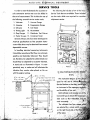
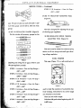
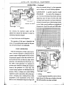
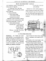
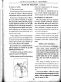
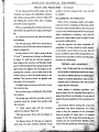
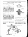
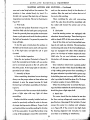
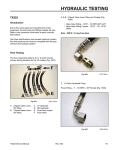
In handling electrical measuring instruments
it should be 'remembered that they are extremely
sensitive and delicately balanced. They should
not, therefore, be subjected to sudden shocks nor
should they be subjected to excessive vibration.
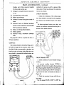
A sland such os illustrated in Figure 1 is. comparatively easy to make and will eliminate the
vibration they receive when placed on the car
with the engine running.
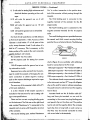
ST -232APORTABLE EL.EC,.RXCT'S'l5;J;Ell{l
,.
(P.E.i.) ' " -
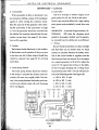
, This instrument (Figure
~) WCI$j~j
oped for the" use,: of. :'()ffiiri..d
Service Statiorisso
that fh~Y..
.
.
"
~
an instrument of the ne.:esspry a.'~,~~irp<~,"~~ii
and durability at I,ow cost,,'
Both voltm!lter and am!l1.~'~.r a.r,eohhl!l,;
horizontaT typet~ ob'';,;n'
sible scale so that inc:liecltil)ns, riiiii,,::)bjl:,
read accur~tely.
2-
-i X20
" .,
. The volt!l1eter has follr'
. . rai~g,.s,:Jwlffal:
SETSCREWS
are selectedbya rotaty:''''-'''''t
I" ANGLE IRON
on
FIGURE 1
the
right hari~side .of ,
AUTO-LITE 'ELECTRICAL
EQUIPMENT
SERVICE TOOlS - Continued
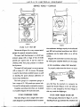
testin~ hiSh resistances and
Out" is a direct connection to the positive term-
electrical devices operating at low volt-
inal of the ammeter without passing through the
ages.
rheostat.
0- 5 volt scale for
The third binding post is connected to the
0-10 volt scale for general use on 6 volt
negative terminal of the ammeter for the 50
circuits.
~-20 vqlt scale for general use on 12 volt
, ampere scale.
The fourth binding post is connected to the
circuits.
negative ammeter terminal for the 10 ampere
0-50 volt scale for general use on 24 and 32
scale.
volt circuits.
For the 0-10 volt scale there are 100 divisions
Two small binding posts are provided between
so that each represents .1 volts. Accuracy of the
the second and third current carrying binding
~oltmeter is held within 1% of all parts of the
posts for the use of external shunts. The following
, scale, except between 6 and 9 volts where it is
held to clr % accuracy. This is necessary as this
latter portion of the scale is the most commonly
: ,;lil5ed;,;jn testing 6 volt circuits.
·""[Ji"-<-('·';('" :~-"
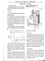
The ammeter has two scales:
FIGURE 3
3-0-10 ampere scale for testing low current
shunts (Figure 3) are available with calibrated
draw.
leads for connections to the P.E.T. Set:
15-0-50 ampere scale for general use in test-
100 ampere capacity-Part Number ST-232A-2
ing automotive circuits.
Depressed zero scales are built into the instru-
200 ampere capacity-Part Number ST-232A-3
, ment to avoid the necessity of changing the am-
500 ampere capacity-Part Number ST-232A-1
- meter connections to obtain negative readings
1000 ampere capacity-Part Number ST -232A-4
s,uch as the amperes discharge required to open
The voltmeter leads are permanently attached
to the instrument and are 27" long with alligator
circuit breakers.
clips on the ends for ease in making connections.
The accuracy of the ammeter is held within 2%
The positive lead is colored red and the negative
of full scale deflection.
/>.. t ohm rheostat of 50 ampere capacity is
lead is black.
Ammeter leads are No.8 flexible cable 37"
included in this instrument for use in setting volt-
long and have pin terminals on one end for
age to test specifications.
connecting to the current carrying binding posts
There are four current carrying binding posts'
on the instrument: The 'first one on the right hand
and special clips on the other end. The positive
side, marked "Resistance In," is connected to the
lead is red and the negative black. The ammeter
rheostat and is in series with the positive terminal
lead clips have a long tooth on each carner so
of the ammeter.
that they may be securely connected to wires
with screw holes in the terminals.
" • Th" second binding post, marked "Resistance
4
AUTO-LITE
ELECTRICAL
EQUIPMENT
SERVICE TOOLS - Continued
•
GAlkil: TeST SET
....... c,.". _
....... , .... c.1'
.""~'.II
T>It rutc.,."IC AUTO-LITe til
......... t ........ _ •
......
1:0"".'51'_
-~,-
. '©'@.~
..
.~o
II
ill
FIGURE 4
FIGURE 5
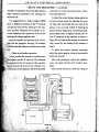
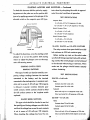
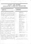
ST-262 V.C.P. TEST SET
tive condensers: leakage, capacity in microfarads
This test unit (Figure 4) is a very compact set of
and 500 volt insulation breakdown test. With it
gauges for general automotive testing.
condensers can be tested either on or off the
The upper right hand gauge is a retard type
vehicle.
pressure gauge with a range of from 0-10-30
Shipped with each tester is an instruction book-
pounds per square inch. It can be used for
let which gives complete details as to its usage.
checking either fuel pump pressure or exhaust
sT-270 UNIVERSAL HORN TEST BRACKET
bock pressure.
The upper left hand gauge is a vacuum gauge
To properly adjust Auto-Lite horns it is neces-
with a range of 0 - 30" of vacuum. This gauge
is used to check intake manifold vacuum as well
as
~hecking
•
II
the spark advance calibration of
vacuum type distributors.
The lower gauge. is a compression gauge. It
FIGURE 6
has a range of 0 - 150 pounds per square inch.
sary that they be mounted on a properly de-
It is used for testing engine compression pressure.
. signed test bracket (Figure 6.) Do not hold any
Complete operating instructions are included
horn in a vise clamped by the horn flange as
in a booklet shipped with each instrument.
this may crack the diaphragm.
sT-265 CONDENSER TESTER
sT-272 HORN FEELER GAUGE SET
This tester (Figure 5) is a single meter instru-
These gauges, illustrated in Figure 7, are for
ment designed to provide three tests for automo-
checking the air gap between the armature and
5
AUT 0 - LITE
E L E CT RIC ALE QUI PM'E NT
SERVICE TOOLS - Continued
ST-281-9
ca.
Armature -
Core Air Gap-
.031 "-.034"
ST-282 VR REGULATOR ADJUSTING TOOL
(Figure 9)
FIGURE 7
core. The set includes two each of ST -272-1 .027
inch thick gauge and ST-272-2 .040 inch thick
FIGURE 9
gauge.
This tool is designed for adjusting the air gap
ST-281 VR REGULATOR GAUGES (Figure 8)
of vibrating type regulators.
This list includes all necessary gauges for the
ST-283 REGULATOR SPRING TENSION
•.• ST·".'-' ••• j+===,
Z•• #, ..... , ... .....
ADJUSTING TOOL (Figure 10)
i
(
FIGURE 10
This tool is used to adjust the armature spring
tension on all two charge and small type vibrat-
...... $"'. . ,... .0.35:==:=
,041
r ...
ing voltage regulators.
st·''''! .. !ll
57-ill/l-S
... I
I
ST-284 OHMETER
FIGURE 8
This meter (Figure 11) is a' self-contained unit
adjusting and setting the air gaps of the TC and
VR type regulators, namely:
ST-281-1 Armature-Core Air Gop Gauge.040"-.042"
ST-281-2 Armature-Core Air Gop Gouge.0595"-.0625"
ST-281-3 C.B. Armature -
Core Air Gap-
.034"-.038"
ST-281-4 CB. Armoture- Core Air GopFIGURE 11
.055"-.062"
used to check the resistance of automotive elec-
ST-281-5 Armature-Core Air Gop Gauge-
trical windings. Instructions for its correct usage
.047"-.049"
are attached to each meter.
ST-281-6 Armature-Core Air Gop Gouge-
There are two scale ranges:
.034"-.038"
0-6 ohms with graduations beginning with .01.
ST-281-7 Armature-Core Air Gop Gauge-
6-600 ohms .
.048"-.051 "
6
•
I,""
,
AUTO-LITE
ELECTRICAL
EQUIPMENT
GENERATORS
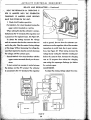
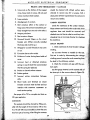
The generator is a device for changing mechan-
hinge type mounting while large trucks and sta-
ical energy into electrical energy. Generators
tionary engines may use flange, base or barrel
are built in many voltages and design to fit the
type mounting. Special mountings are often de-
special requirements of the application for which
signed to fit applications not adaptable to the
they are intended. Some generators are com-
standard hinge or flange types. The type of drive
pletely sealed to exclude moisture or dust. Others
also varies for different applications.
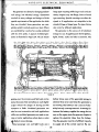
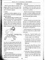
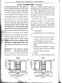
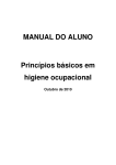
are ventilated by a suction fan usually combined
The generator is the source of all electrical
with the drive pulley. A typical ventilated gen-
energy on a car. It supplies power for the ignition,
erator is illustrated in Figure 29. The air stream
lights, heater, radio and other accessories. The
--,.------ ----------- --
--
---,-
_.- ----._---------- - FIGURE 29
------
passing over the armature and field coils carries
battery stores some of the generated energy in
away the excess heat and allows a much higher
chemical form to be used when the generator is
output without the danger of burning out the
not running. The battery is not a source of elec-
armature or fields. Ventilated generators are
tricity but only a storage reservoir. In starting for
'/
\'
,,~ed on most automotive and truck applications
instance the battery supplies the energy but as
while non-ventilated generators are used on ma-
soon as the engine starts the generator begins to
rin(e or tractor applications where dust or water
replace the electricity taken from the battery.
'fie likely to cause damage,
Thus the generator must be of sufficient capacity
~,Most passenger cars and light trucks use a
/"
to supply all of the current used on the car.
26
AUTO-LITE
ELECTRICAL
EQUIPMENT
GENERATORS - Continued
1-
sufficient capacity to cronk the engine and sup-
L
ply enough electrical energy for the ignition
"
"
system for starting the engine.
As the automobile has developed there has
been an increase in the number of electrical uses.
"
",
The lights have been increased in number and
,
capacity, electric horns have become standard
COLD
.LU
; HOT
OUTPUT
L600
equipment, electric windshield wipers are being
PU
1600
2400
3200
4000
4600
GENEJIATOR
5600
641)0
7200
8000
R.P.M.
FIGURE 30
used and the newer carS are using solenoid controlled transmissions, electric window lifts, radios
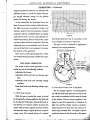
third brush generator and its connection to the
and many other electrical accessories. These de-
circuit breaker are shown in Figure 3l.
This type of unit is restricted to applications
velopments have come gradually and with each
requiring low output generators.
new use of electricity it was necessary to increase
B"ITTERY TER/'1/N/9L "B'
the capacity of the generator.
There are two main types of generators. These
are the third brush generator and the shunt gen-
(,'
erator.
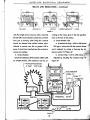
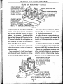
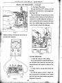
THIRD BRUSH GENERATORS
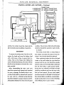
The output of third brush generators is con/'P1IN
trolled by one of the following methods:
Adjustable third brush.
Adjustable third brush and two-charge regulator.
Adjustable third brush and vibrating voltage
regulator.
FIGURE 31
Fixed third brush and vibrating voltage regu-
2-Third Brush Control with TC Regulator
lator.
The two charge regulator was developed for
I-Third Brush Control
I
use with t-he third brush generator so that its out-
With this type of control the output is varied
put varied in accordance with the state of charge
by changing the voltage applied to the field coils
of the battery' The two charge regulator is de-
by moving the third brv.sh. Moving this brush in
signed to permit the generator to charge at its
the direction of armature rotation increases the
high rate until the voltage reaches a predeter-
output while moving it against armature rotation
mined maximum at which time the
decreases the output. Figure 30 shows a typical
duced approximately 50%. The higher output: is
output curve. The internal wiring of a typical
produced whenever the demands on the gener-
27
outpu~~s· re-
.
AUTO-LITE
elECTRICAL
GENERATORS -
EQUIPMENT
Continued
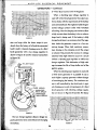
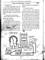
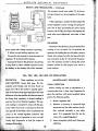
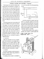
3-Third Brush Control with VR Regulator
"
When a vibrating type voltage regulator is
DOT UT
"
"
"
used with a third brush generator the output conHOT 0
forms closely with the requirements of the battery
T
and connected load. The regulator holds the gen-
"
•
•
•
OUTPUT WITH
erated voltage constant under wide variations
C-
"TOR OPEA TI
of loading. Thus the charging rate varies to allow
800
1600
2400
3200
4000
4800
51100
GE:N£R"TOR R.P. M
6400
a high current when the battery is low or when a
7200, 8000
large load is being used. if the battery is fully
FIGURE 32
charged and there is no accessory load the reguator are large while the lower output is pro-
lator holds the generator output to a low sus-
duced when the battery is full and the connected
taining charge. When high resistance connec-
load is small. A typical charging curve of a third
tions develop in the charging circuit the output
brush generator with a two charge regulator is
is reduced. This prevents the increase in voltage
shown in Figure 32 and the internal connections
obtained when high resistance occurs in a circuit
without a vibrating type regulator or with a two
charge regulator. This elimination of high voltage increases the life of lamp bulbs and of the
ignition system.
When the vibrating type regulator is used with
a third brush generator it is possible to use a
much higher capacity generator without danger
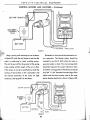
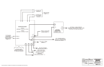
of overcharging the ballery. The maximum current is still controlled .by the third brush. A typical charging curve and wiring diagram of a third
B~USH
brush generator with vibrating voltage regula-
INSt.lt.I9TEO
I'1A/N BIi't.lSH
C,Ii'Ot.lNOED
I'1A/N BIi'I./SH
tion are shown in Figures 34 and 35. The heavy
"
"
"
FIGURE 33
The two charge regulator allows a larger ca-
.'
pacity generator to be used without overcharging
AP!'~<:lXIt.!A"! OUTNT TO FULLY
CHARGEo S,o,TTERY AND WIT'"
NO <':ONNECTED LOAO
GtNERATOR
the battery.
RP.M.
FIGURE 3.
28
AUTO-LITE
ElECTRICAL
GENERATORS -
EQUIPMENT
Continued
shows the internal wiring of a shunt generator
and a voltage and current limiting regulator.
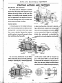
MAINTENANCE
A periodic inspection should
PROCEDURE
be made of the charging cir-
cuit. The interval between these checks will vary
depending upon the type of service. Dirt, dust
and high speed operation are factors which contribute to increased wear of the bearings, brushG.eGVNO£lJ 1'1,.qIN
es, etc. Under normal conditions an inspection of
the generator should be made each 5000 miles.
TO a,qT.
FIGURE 35
line indicates the maximum output and the
dotted lines indicate the decrease in output as
the battery becomes charged.
4-Fixed Third Brush with VR Regulator
The operation of this type is identically the
same as the preceding type except that the posi-
,
,
APPFlO)(IMAT~
OUTPUT TO FULLY
CHARGED eATTEFlY ANO WITH
1>10 CONNECT~ LOAD
•
tion of the third brush is not adjustable.
400
800
1200
1800
2<)00
G<;NERATOR
2<100
~eoD
R.P.M.
3i1OO
31100
4000
4400
4800
FIGURE 36
SHUNT GENERATORS
With the development of high output generators it became desirable to eliminate the decrease in output at high speeds and also to lower
the generator speed at which the maximum output is produced. This was done by using a shunt
generator and eliminating the third brush control. With a shunt generator it is necess.ary to
IN$UlATeD J11;IIIN
provide some method for limiting the maximum
SA!lJSH
output of the. generator to a safe value. The
G.eot./NDEIJ HI9IN
~I.I$H
~urrent limiting regulator was developed for this
purpose. When a voltage and current limiting
regulator is used in conjunction with a shunt gen-
1. Wiring
erator a charging rate is obtained that is fully
A visual inspection should be made of all wir-
dependent on the requirements of the circuit.
ing to be sure that there are no broken wires and
Such a curve is illustrated in Figure 36. Figure 37
that all connections are clean and tight.
29
", ,'; "
~.~ i !:~
'!"_
"
;"
.
.....- ,
,'-
AUTO-LITE
ELECTRICAL
EQUIPMENT
GENERATORS - Continued
5. Lubrication
2. Commutat""..
Add 5 to 10 drops of medium engine oil (A
If the commutator is dirty or discolored it can
be cleaned by holding a piece of 00 sandpaper
good grade of S.A.E. No. 20 oil) to the oilers.
against it while running the armature slowly.
Grease cups should be filled with a high melting
Blow the sand out of the generator after clean-
point grease and periodically turned down one
ing the commutator. If the commutator is rough
turn.
or worn the generator should be removed from
GENERATOR
At periods of approximately 15,-
the vehicle, the armature removed and the com-
OVERHAUL
000 miles the charging circuit
mutator turned down. See page 31 for instruc-
should be thoroughly checked and the genera-
tions on this operation.
tor removed from the vehicle and reconditioned.
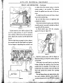
1. Wiring
3. Brushes
Be sure that all connections are clean and tight
The brushes should slide freely in their holders.
and that there are no broken wires. To check
If the brushes are oil soaked or if they are worn
connect an ammeter between the battery term-
to less than one half of their original length they
inal of the circuit breaker or regulator and the
should be replaced. See page 32 for servicing
lead removed from this terminal. Run the engine
instructions.
at a speed equivalent to 20 M.P.H. Adjust the
current to 10 amperes by turning on the lights.
4. Brush Spring Tension
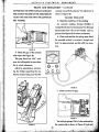
At this 10 ampere charging rate a voltage read-
The brush spring tension should be checked.
ing should be taken with a 10 volt voltmeter between the following points. See Figure 38.
If the tension is excessive the brushes and commutator will wear very rapidly while if the ten-
a. BG to GG 0 volts
sion is low arcing between the brushes and com-
b. BG to RG 0 volts
mutatorand reduced output will result. See page
c. RG to GG 0 volts
34 for test figures.
d. RA to GA .1 volts
VOLTS AMPS OHMS
o
o
10
o
o
10
o
10
o
.01
RA
.I
10
.I
10
.01
BB
BATTERY
AR
FIGURE 38
30
FRAME
o
AUTO-LITE
ELECTRICAL
EQUl,PMENT
GENERATORS - Continued
e. RS to SS .1 volts
If readings higher than these are obtained the
STEEL STRIP HELD ON,'
ARMATURE SLOT
wiring should be checked for high resistance
connections.
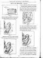
2. Armature
The armature should be visually inspected for
mechanical defects.
If the commutator is rough or worn it should
be turned down in a lathe. After turning the commutator the mica should be undercut to a depth
of 1/32". When undercutting the mica the cut
should be square and free from burrs. The maximum eccentricity of the commutator is not to exceed .0003 inches.
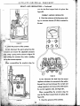
For testing armature circuits it is advisable to
use a set of test probes such as shown in Figure
FIGURE 40
39.
ItQ VOLT
the steel strip will vibrate.
UNE
3. Field Coils
Using the test probes illustrated in Figure 39
TEST POINTS
check the field coils for both opens and grounds.
To test for open coils. connect the probes to
10 wArT
LAMP
the two leads of each coil. If the lamp fails to
light the coil is open and should be replaced.
FIGURE 39
To test for grounds place one probe on the
•
To test armatures for grounds connect one
generator frame and the other to the field coil
point to the core or shaft (not on bearing sur-
terminals. If a ground is present the lamp will
faces) and touch a commutator segment with the
light and the coil should be replaced.
other probe. If the lamp lights the armature
4. Brush Holders
winding is grounded and the armature should be
With the test probes check the insulated brush
replaced.
To test for shorted armature coils a growler
holder to be sure it is not grounded. Touch the
(Figure 40) is necessary. Place the armature on
insulated brush holder with one probe and a
the growler and hold a thin steel strip on the
convenient ground ali the C.E. Plate with the
armature core. The armature is then rotated
other probe. If the lamp lights it indicates. a
slowly by hand and if a shorted coil is present
. grounded brush holder.
31
. ',:dt'L'
AUTO-LITE
ELECTRICAL
EQUIPMENT
GENERATORS - Continued
Inspect the brush holders for distortion and
When assembling bearings or end heads that
improper alignment. The brushes should swing
are equipped with oil wicks always remove the
or slide freely and should be perfectly in line
wick and replace it only after the armature and
with the commutator segments.
end heads are assembled.
Absorbent bronze bearings and wicks should
5. Brushes
Brushes that have been subjected to oil or are
be soaked in oil before assembling and the boll
worn to one-half or less of their original length
bearings should be pocked one half full with a
should be replaced.
heat resisting grease before assembly.
When replacing brushes it is necessary to seat
7. Lubrication
them so that they have 100% surface contacting
on the commutator. The brushes should be
Generator armatures may be mounted in boll
sanded to obtain this fit. This can be done by
bearings or in oil absorbent bronze bearings.
drawing a piece of 00 sandpaper between the
The drive end bearing is usually a boll bearing
commutator and brush and against the brush
while the commutator end bearing may be either
holder as illustrated in Figure 41. Do not sand
ball or absorbent bronze depending on the size
and application of the generator.
Nearly all generators are provided with oilers
at both ends. These oilers are usually of the following types:
SANDPAPER PULLED
AGAINST BRUSH HOLDER
a. Hinged top - These are located over the
bearing and should be given 5 to 10 drops .
of medium engine oil every 5000 miles.
b. Swinging type-This type is used only on
fIGURE
the commutator end cap cover and should
~I
be filled full of medium engine oil every
too much as it merely shortens brush life. After
5000 miles.
sanding the brushes blow the sand and carbon
should
dust ,out of the generator. The generator
.
c. Cup and wick oilers-This type is found
then be run under load long enough to secure
under the bearing. The cup should be re-
a perfect brush fit. Generators are not to be
moved and filled 'with medium oil every
tested for output until after the brushes are
5000 miles.
seated.
d. Grease cups-These are usually located at
6. Assembly of Generator
the side of the end plates. The cups should
.. When assembling absorbent bronze bearings
be given one turn every 5000 miles. When
' .. ··.~Iway~. use the proper arbor as these arbors are
refilling cups use a high melting point
",.' ,dei,igrl.ed to give the proper bearing fit.
grease.
32
AUTO-LITE
ELECTRICAL
EQUIPMENT
GENERATORS - Continued
e. Cup oilers-This lype of oiler has a spring
8. Generator Test
caver and is found at the side of the end
After the generator is assembled and the
plates. The cups should be filled with medi-
brushes are properly fitted the generator should
um engine oil every 5000 miles.
be bench tested under conditions of speed, volt-
When the generator is disassembled and
age, amperes and temperature as near as pos-
cleaned the absorbent bronze bearings should
sible the same as when in operation on the car
be soaked in oil before assembling and the ball
before installing on the car. See pages 34 to 39
bearings should be packed one half full with a
for complete test data.
high melting point grease. Care must be taken
All generators should be polarized with the
not to over-lubricate any of the bearings as the
car battery before running. This can be done by
surplus oil may deposit on the commutator or
using a jumper from the starting switch battery
brushes allowing them to become oil soaked and
terminal to the armature terminal of the gen-
seriously affect the operation of the generator.
erator.
,
33
AUTO-LITE
EL E C T R I C'AL
EQUIPMENT
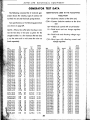
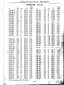
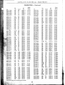
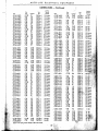
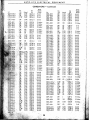
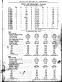
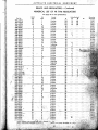
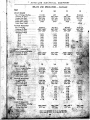
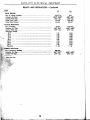
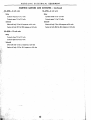
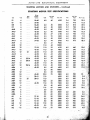
GENERATOR TEST DATA
ABBREVIATIONS USED IN THE FOLLOWING
The following numerical list of Auto-lite gen-
TABULATION
erators shows the rotation, type of control, test
to which it is set and the, brush spring tension.
CW-Clockwise rotation at the drive end.
CCW-Counter clockwise rotation at the drive
end
Test specifications on the following generators
are shown on page 39.
CB-Third brush control with circuit breaker
NOTE:-Where the suffix letter has been omit-
TC-Third brush and two charge regulator
control
ted the test data is the same as given for the
VR-Third brush and vibrating voltage regulator
c;VR-Shunt type with vibrating current and
voltage regulator
straight nlimber. In a few instances the test data
is not the same and in such cases the units are
listed separately.
Spring
Rot.
D.E.
GAG-4133
.Ci3AG:4145
·GAG-4146
. GAG-4147
GAG'4148
-GAG-4t49
. GAG-4150
GAG-4151
GAL-4336
GAL-4340
GAM-4504
'GAM-4601
GAP-4133
.13AP-4135
\~AP·4140
57
58
59
60
Control
CB
CB
~~W CB
TC
CW
CCW TC
CCW CB
CW
CB
CW
CB
CW
CB
CW
TC
TC
CW
CW
TC
CW
TC
CCW TC
CCW CB
CW
TC
CCW TC
CW
TC
CW
CB
CW
TC
CW
TC
CW
CB
CW
CB
CW
TC
CW
CB
CCW CB
CW
CB
CCW CB
CW
CB
CW
CB
CW
CB
(B
CW
CW
CB
CW
CB
CCW CB
CW
CB
CCW CB
CW
CB
CW
TM'
No.
Tension
Rot.
Ounces
GAE-O
GAE-O
GAE-O
GAE-O
GAE-O
GAE-O
GAE-o
GAE-O
GAE-O
GAE·o
GAE-o
GAE·o
GAE-o
GAE-O
GAE-O
GAE-o
GAE·o
GAE-o
20-26
20-26
20-26
20-26
20-26
20-26
20-26
20-26
20-26
20-26
20·26
20-26
20·26
20-26
20·26
20-26
20-26
20·26
GAG-O
GAG-O
GAG-O
GAG-O
GAG-O
GAG-O
GAG·O
GAG-O
22·27
22-27
22-27
22-27
22-27
22-27
22-27
22-27
GAL-O
GAL-o
17-22
17-22
GAM-O
GAM-O
18-22
18-22
GAP-O
GAP-O
GAP-O
GAP-O
GAP-O
GAP-o
GAP·O
22-27
22-27
22-27
22-27
22-27
22-27
22-27
GAR-O
17-22
Unh
I
GAR-4316
GAR-4502
GAR-4513
GAR-4515
GAR-4518
GAR·4520
GAR-4521
GAR.4522
GAR-4524
GAR·4525
GAR-4527
GAR-4534
GAR·4535
GAR·4536
GAR-4537
GAR·4540
GAR-4541
GAR·4542
GAR·4543
GAR-4544
GAR-4545
GAR-4546
GAR·4547
GAR-4548
GAR-4549
GAR-4550
GAR-4551
GAR-4553
GAR·4554
GAR·4555
GAR-4601
GAR·4603
GAR·4604
GAR·4605
GAR-4606
GAR-4607
GAR·4608
GAR-4609
GAR-4610
GAR·4611
GAR-4612
Test
D.!.
Control
No.
CCW
CW
CW
CW
CCW
CCW
CW
CW
CW
CW
CCW
CW
CW
CCW
CW
CW
CW
CCW
CW
CCW
CW
CCW
CW
CCW
CW
CW
CCW
CCW
CW
CW
CW
CW
CW
CW
CW
CW.
CW
CW
CW
CW
CW
CB
C8.
CB
CB
CB
CB
CB
CB
CB
CB
CB
CB
CB
CB
CB
CB
CB
CB
CB
CB
CB
CB
CB
TC
CB
TC
TC
TC·
CB
TC
CB
CB
CB
TC
TC
CB
TC
TC
TC
TC
TC
GAR-o
GAR-O
GAR-O
GAR-O
GAR-O
GAR-O
GAR-O
GAR-O
GAR·O
GAR-O
GAR-O
GAR-O
GAR-O
GAR-O
GAR-O
GAR·O
GAR-O
GAR-O
GAR-O
GAR-O
GAR-o
GAR-O
GAR-O
GAR-O
GAR-O
GAR-O
GAR-O
GAR-O
GAR-O
GAR-O
GAR-5
GAR-5
GAR-3
GAR-4
GAR-3
GAR-3
GAR-5
GAR-4
GAR-4
GAR-5
GAR-3
.34
;
,
.;,. -.,."
Spring
Tension
Ounces
17-22
18-22
18-22
18-22
18·22
18-22
18-22
18-22
18·22
18-22
17-22
18-22
18-22
-r 8-22
18-22
18-22
18·2.2
17-22
18-22
17-22
18·22
17·22
18-22
17-22
18·22
18-22
18·22
18-22
18-22
18-22
50-60
50·60
50-60
50-60
50-60
50-60
50-60
50-60
50·60
50-60
50·60
f
AUTO-liTE
eleCTRICAL
EQUIPMENT
GENERATORS - Continued
Spring
Rot.
~
Unit
.~
I
•
D.E.
Control
T..,
Tension
No.
OuncM
GAR-4613-3
GAR-4613-4
GAR-4614-4
GAR-4614-5
GAR-4616
GAR-4617
GAR-4618
GAR-4619
GAR-4620
GAR-4621
GAR-4622
GAR-4623
GAR-4624
GAR-4625
GAR-4626
GAR-4627
GAR-4630
GAR-4631
GAR-4632
GAR·4633
GAR-4634
GAR-4635
GAR-4701
GAR_4702
CW
CW
CW
CW
CW
CW
CW
CW
CW
CCW
CW
CW
CW
CW
CW
CW
CW
CW
CW
CW
CW
CW
CW
CW
TC
TC
TC
TC
TC
TC
C8
TC
TC
TC
CB
TC
TC
TC
CB
TC
TC
TC
CB
C8
CB
TC
TC
CB
GAR·3
GAR-4
GAR-4
GAR-5
GAR-3
GAR-3
GAR-2
GAR-3
GAR-5
GAR-3
GAR-3
GAR-4
GAR-5
GAR-5
GAR-3
GAR-3
GAR-5
GAR-5
GAR-3
GAR-3
GAR-2
GAR-5
GAR·6
GAR-O
GAS-4102
GAS-41 02-1
GAS-4102A
GAS-4102B
GAS-4102C
GAS-4103
GAS-4104
GAS-41 04·1
GAS-4104A
GAS-4104B
GAS-4106
.' GAS-4108
'u,,,GAS-4110
. GAS-4111
GAS-4114
GAS-4119
GAS-4120
GAS-4120-1
GAS-4120A
GAS-4124
GAS-4125
GAS-4125-1
GAS-4126
GAS-4128
GAS-4129
GAS-4131
GAS-4132
GAS-4136
GAS-4139
GAS-4140
GAS-4141
GAS-4144
GAS-4145
GAS-4148
GAS-4149
GAS-41SO
GAS-4151
CCW
CCW
CCW
CCW
CCW
CW
CW
CW
CW
CW
CW
CCW
CW
CCW
CCW
CW
CW
CW
CW
CCW
CW
CW
CCW
CW
CW
CW
CCW
CW
CW
CW
CW
CW
CW
CW
CCW
CCW
CW
CB
CB
C8
CB
CB
CB
CB
CB
CB
CB
CB
CB
C8
C8
CB
CB
C8
CB
C8
CB
C8
CB
CB
CB
CB
CB
CB
TC
CB
CB
CB
CB
TC
TC
TC
CB
CB
GAS-O
GAS-1
GAS-1
GAS-1
GAS-O
GAS-1
GAS-O
GAS-1
GAS-O
GAS-O
GAS-O
GAS-O
GAS-O
GAS-O
GAS-O
GAS-O
GAS-O
GAS-1
GAS-O
GAS-1
GAS-O
GAS-1
GAS-O
GAS-O
GAS-O
GAS-1
GAS-O
GAS·1
GAS-O
GAS-O
GAS-O
GAS-O
GAS-O
GAS-1
GAS-1
GAS-1
GAS-1
Spring
Rot.
15-20
15-20
15-20
15-20
15-20
15-20
15-20
15-20
15-20
15-20
15-20
15-20
15-20
15-20
15-20
15-20
15·20
15-20
15-20
15-20
15-20
15-20
15-20
15-20
15-20
15-20
15-20
15-20
15-20
15-20
15-20
15-20
15-20
15-20 .
15-20
15-20
15-20
D.E.
Control
No.
Ouneu
GAS-4152
GAS-4157
GAS-4159
GAS-4160
GAS-4161
GAS-4162
GA5-4163
GAS-4164
GAS-4165
GAS-4166
GBB-4304
GBE-4201
G8E-4202
GBE-4203
GBE-4204
GBE-4205
GBE-4206
G8E-4207
GBE-4208
GBE-4209
GBE-4301
GBG-4601
GBG-4602
GBG-4603
GBG-4604
GBG-4606
G8G-4607
GBG-4608
GBG-4609
G8G-4610
G8G-4611
C8
TC
TC
C8
C8
C8
TC
C8
TC
C8
TC
C8
CB
C8
C8
C8
CB
C8
C8
TC
C8
CVR
CVR
CVR
CVR
CVR
CVR
CVR
CVR
CVR
CVR
GAS-O
GAS-O
GAS-1
GAS-O
GAS-O
GAS-o
GAS-O
GAS-O
GAS-O
GAS-1
GBB-o
GBE-o
GBE-O
GBE-o
G8E-0
ClBE-O
GBE-o
GBE-O
G8E-0
GBE-o
GBE-O
GBG-O
GBG-o
GBG-o
GBG-O
GBG-O.
GBG-o
GBG-o
GBG-O'
GBG-o
GBG-o
15-20
15-20
15-20
15-20
15-20
15-20
15-20
15-20
15-20
15-20
22-27
50-60
50-60
50-60
50-60
50-60
50-60
50-60
50-60
50-60
17-22
23-26 .
23-26
23-26
GBJ-4601
TC
CW
C8
CW
TC
CW
C8
CW
C8
C8
CW
CW . C8
CW
CB
CB
CW
CB
CW
CB
CW
CB
CW
CB
CW
CB
CW
CB
CW
CB
CW
CB
CW
CB
CW
TC
CW
CB
CW
CCW CB
CB
CW
CCW C8
TC
CW
CW
C8
CB
CW
CW
CB
GBK-4601
G8K-4602
GBI<-4603
G8K-4604
GBM-4601
GBM-4602
GBM-4603
G8M-4604
GBM-4606
GBM-4607
GBM-4608
GBM-4608C
GBM-4609
GBM-4610
GBM-4611
GBM-4612
GBM-4613
GBM-4616
GflM-4617
GBM-4619
GBM-4620
GBM-4801
GBM-4802
GBM-4803
GBM-4804
GBM-4805
tThird brush spring tension should be 50 to 60 ounces.
35
Tension
CCW
CW
CW
CW
CW
CW
CW
CW
CW
CCW
CW
CW
CCW
CW
CCW
CW
CCW
CCW
CW
CCW
CW
CW
CW
CW
CW
CW
CW
CW
CW
CCW
CW
Unit
50-60
50-60
50·60
50-60
50-60
50-60
50-60
50-60
50-60
50·60
50-60
50-60
50-60
50-60
50-60
50-60
50-60
50-60
50-60
50-60
50-60
50-60
18-22
18-22
Test
CW
GBJ-O
GBK-2·
G8K-1 .
GBK-o
GBK-O
GBM-O
GBM-O
GBM-1
GBM-1
50-60
GBM-1
50-60
GBM-1
50-60
GBM-O 50-60
G8M-1
50-60
GBM-O 50-60
GBM-5 50-60
GBM·4 50·60
GBM-O 50-60
GBM-1
50-60
G8M-1 . 50-60
GBM-5 50-60
G8M-5 50-60
50-60: .
GBM-1
GBM-5
37-44t
G8M-5
37-44+
GBM-1 _ 37-44.·.· .
GBM-5 37-44ti\'
GBM-5
37-44f'
AUTO-LITE
ELECTRICAL
EQUIPMENT
GENERATORS - Continued
Spring
Spring
Rot.
D.E.
Unit
GBM-4806
GBM-4807
GBM-4808
GBM-4809
GBM-4810
GBR-4501
GBR-4502
GBR·4601
GBR-4602
GBR-4603
GBR-4604
GBR-4605
GBR-4607
GBR-4608
GBR-4609
GBR-4611
GBR-46H
~
GBS-4501
GBS-4502
GBS-4602
GBY-4601
GBY-4801
GBY-4802
GCB-4601
GCB-4802
GC8-4803
GCB-4804
GCB-4805
GCB-4806
CW
CW
CW
CW
CW
CW
CCW
CW
-CW
CW
CW
CW
CW
CW
CW
CW
CW
CCW
CW
CW
CW
CCW
CW
CW
CCW
CW
CW
CW
CW
CW
CCW
CW
CW
CW
CCW
CW
CW
CW
CW
CW
CW
CW
CW
CW
CW
CW
CW
CW
CW
CW
CW
CW
CW
CW
CW
CW
CCW
CW -
Control
Test
No.
GBM-4
CB
GBM-1
TC
TC . GBM-6
GBM-5
TC
GBM-1
CB
CB
GBR-3
GBR-3
CB
GBR-5
TC
GBR-4
TC
GBR-4
TC
GBR-S
TC
GBR-5
TC
GBR-5
TC
GBR-5
TC
GBR-5
TC
GBR-5
TC
GBR-5
TC
GBS-l
CB
GBS-1 .
CB
GBS-O
TC
GBS-O
TC
GBS-O
TC
GBU-O
TC
GBU-O
TC
GBU-O
TC
GBU-O
TC
GBU-O
TC
. GBU-O
CB
G8U-0
TC
GBU-O
CB
GBU-O
CB
GBU-O
TC
GBU-O
TC
GBU-O
TC
GBU-O
CB
CYR GBW-O
CVR GBW-O
CVR GBW-O
CYR GBW-O
CYR GBW-O
CVR GBW-1
CVR GBW-1
GBX-5
TC
GBX-5
TC
GBY-5
TC
GBY-5
TC
GBY-5
TC
GCB-O
CYR
CYR GCB-o
CYR GCB-O
CYR GCB-O
CVR GCB-O
CYR GCB-O
CYR GCB-O
.CVR GCB-O
CYR GCB-O
CVR GCB-O
CYR GCB-O
Tension
Ounces
Test
Rot.
D.E.
Unit
GCB-4815
GCB-4816
GC8-4817
GCB-4818
GCB-4820
GCB-4821
GCD-4801
GCD-4803
GCD-4804
GCD-4805
GCD-4806
GCD-4807
GCE-4803
GCE-4804
GCE-4806
GCE-4807
GCE-4808
GCE-4809
GCE-4810
GCE-4812
GCE-4813
GCE-4814
GCE-4815
GCE-4816
GCE-4817
GCE-4822
GCG-4601
GCH-4601
GCH-4602
GCH-4603
GCH-4604
GCH-4606
GCH-4607
GCH-4608
GCH-4609
GCJ-4801
GCJ-4802
GCJ-480J
GCJ-4804
GCJ-4805
GCJ-4807
GCJ-4808
GCJ-4810
GCJ-4811
GCJ-4812
GCJ-4813
GCJ-4814
GCJ-4815
GCJ'4816
GCK-4801
GCK-4802
GCK-4804
GCK-4805
GCK-4806·
GCK-4807
GCM-4802
GCM·4803
GCM,4804
37-44 t
37-44t
37-44t
37-44 t
37-44 t
18-22
18-22
50-60
50-60
50-60
50-60
50-60
50-60
50-60
50-60
50-60
50-60
18-22
18-22
50-60
50-60
50'60
50-60
50-60
50-60
50-60
50-60
50-60
50-60
50-60
50-60
50-60
50-60
50-60
50-60
53 Max.
53 Max.
53 Max.
53 Max.
53 Max.
53 Max.
53 Max.
41-52
41-52
41-52
64-68
64-68
64-68
64-68
64-68
64-68
64-68
64-68
64-68
64-68
64-68
64-68
64-68
sprin_9 _ten.si~n should ,be.50 to 60 o·unces.
36
CW
CW
CW
CW
CW
CW
CW
CW
CW
CW
CCW
CW
CW
CW
CW
CW
CW
CW
CW
CW
CW
CW
.
Control
CYR
CVR
CVR
CVR
CVR
CVR
CYR
CVR
CVR
CVR
CVR
CVR
CVR
CVR
CYR
CVR
CVR
CVR
CVR
CVR
CVR
CVR
CVR
C\'II
CVR
CW
CW
CYR
CYR
CW
CCW No
CVR
CW
CW
CVR
CVR
CW
CW
CVR
CW
CVR
CW
CVR
CYR
CW
CYR
CW
VR
CW
YR
CW
CW ._ YR
CB
CW
CW
YR
VR
CW
CW
VR
CW
YR
VR
CW
CCW CB
CCW CB
CB
CW
CW
CCW ~~'j'
',','"
(:VR
CW
CW
CVR
cew CVR
CYR
CW
eW, CVR
J:.CW CVR
TC
CW
CB
CW
TC
CW
Tension
No.
Ounces
GCB-O
GCB-o
GCB-o
GCB-o
GCB-O
GCB-o
GCD-o
GCD-o
GCD-O
GCD-o
GCD-O
GCD-O
GCE-O
GCE-O
GCE-O
GCE-O
GCE-O
GCE-o
GCE-o
GCE-O
GCE-O
GCE-O
GCE-O
GCE-O
GCE-o
GCE-O
GCG-o
64-68
64-68
64-68
64-68
64-68
64-68
55-65
55-65
55-65
55-65
55-65
55-65
64-68
64-68
64-68
64-68
64-68
64-68
64-68
64-68
64-68
64-68
64-68
64-68
64-68
64-68
24-36
23-26
23-26
2.3-26
23-26
23-26
23-26
23-26
23-26
53 Max.
53 Max.
53 Max.
53 Max.
53 Max.
53 Max.
53 Max.
53 Max.
53 Max.
53 Max.
53 Max.
53 Max.
53 Max:
53 Max.
53 Max.
53 Max.
53 Max.
53 Max.
53 Max .
53 Max.
53 Max.
53 Max.
53 Max.
GCH~O
GCH-O
GCH-O
GCH-o
GCH-o
GCH-1
GCH-1
GCH-O
GCJ-O
GCJ-O
GCJ-O
GCJ-1
GCJ-O
GCJ-2
GCJ-O
GCJ-2
GCJ-o
GCJ-3
GCJ-3
GCJ-3
GCJ-3
GCJ-3
GCK-O
GCK-O
GCK-1
GCK-O
GCK-1
GCK-1
GCM-4
GCM-4
GCM-4
AUTO-LITE
ELECTRICAL
EQUIPMENT
GENERATORS - Continued
Rot.
f'-,
Unit
D.E.
Test
Control
GCM-4805
GCM-4806
GCM-4807
GCM-4808
GCM-4809
GCM-4810
GCM-4811
GCM-4812
GCM-4814
GCM-4815
GCM-4816
GCM-4818
GCM-4820
GCM-4821
GCM-4822
GCM-4824
GCM-4825
GCM-4827
CCW
CW
CW
CW
CW
CW
CW
CW
CCW
CW
CW
CW
CCW
CW
CW
CW
CW
CW
TC
CB
CB
CB
CB
TC
CB
CB
CB
TC
TC
CB
CB
CB
TC
CB
CB
TC
GCO-4801
GCO-4802
GCO-4803
GCO-4804
GCO-4806
GCO-4807
GCO-4808
GCP-4801
GCP-4802
GCR-4801
GCR-4802
GCR-4803
GCR-4804
CW
CW
CW
CW
CW
CW
CW
CW
CCW
CW
CW
CW
CW
CVR
CVR
CVR
CVR
CVR
CVR
CVR
CVR
CVR
CVR
CVR
CVR
CVR
GCS-4802
GCS-4803
GCS-4804
GCS-4805
GCS-4806
GCS'4807
GCS-4808
GCS-4809
GCS-4810
GCS-4811
GCS-4812
GCS-4813
GCS-4814
GCS-4815
CW
CW
CW
CW
CW
CCW
CW
CW
CW
CW
CW
CW
CW
CW
TC
TC
TC
TC
TC
CB
TC
TC
TC
TC
TC
TC
TC
TC
GCT-4801
CW
CB
GCT-4802
CW
VR
GCT-4803
CB
CW
GCT-4804
VR
CW
GCT-4S05
CW
VR
GCT-4806
CW
VR
GCT-4807
CW 'VR
GCT-480B
CW
VR
GCT-4810
CW
CB
GCT-4811 .' -"CW
CB
GCT-4812
CW
VR
.(CW
CVR
GCW"1I802'
CW
GCW14804.
CVR
tT~'!rd brush spri-ng tension should
No.
GCM-4
GCM-4
GCM-4
GCM-4
GCM-4
GCM-4
GCM-4
GCM-O
GCM-o
GCM-4
GCM-4
GCM-O
GCM-O
GCM-O
GCM-4
GCM-4
GCM-4
GCM-O
Spring
Tension
Ounces
53
53
53
53
53
53
53
t53
t53
53
53
t53
t53
t53
53
53
53
t53
Max.
Max.
Max.
Max.
Max.
Max.
Max.
Max.
Max.
Max.
Max.
Max.
Max.
Max.
Max.
Max.
Max.
Max.
Rot.
Unit
GCW-4805
GCW-4806
GCX-4501
GCX-4502
GCX-4503
GCY-4601
GCY-4603
GCY-4604
GCZ-4803
GCZ-4805
GCZ-4806
GCZ-4807
GDA-4801
GDA-4802
GDA-4803
GDA-4804
GDA-4805
GCO-o 53 Max.
GDA-4806
GCO-O 53 Max.
GDA-4807
GCO-o 53 Max.
GDA-4808
GCO-O 53 Max.
GDA-4809
GCO-O 53 Max.
GDA-4810
GCO-o 53 Max.
GCO-o 53 Max.
GDB-4802
GDB-4803
GCP-o
53 Max.
GDB-4804
GCP-o
53 Max.
GDB-4805
GCR-O
53 Max.
GDB-4810
GCR-O
53 Max.
GDB-4812
GCR-O
53 Max.
GDB-4813
GCR-O
53 Max.
GDB-4814
GDC-4601
GCS-5
53 Max.
GCS-5
53 Max.
GDE-4101
53 Max.
GCS-5
GDE-4102
GCS-5 . 53 Max.
GDE-4103
GCSc5
53 Max.
GDE-4104
53 Max.
GCS-1
GDE-4105 .
53 Max.
GCS-5
GDE-4106
53 Max.
GCS-5
GCS-5
53 Max.
GDF-4801
GCS-5
53 Max.
GDF-4802
GCS-5
53 Max.
GDF-4803
GCS-5
53 Max.
GDF-4804
GCS-5
53 Max.
GDF-4805
53 Max.
GCS-5
GDF-4806
GDF-4807
GCT-1
53 Max.
GDF-4808
GCT-O
53 Max.
GDF-4812
53 Max .. GDF-4813
GCT-1
GCT-o
53 Max.
GDF-4814
GCT-O
53 Max.
GDF-4815
53 Max.
GCT-O
. GDG-4501
GCT-o
53 Max.
53 Max.
GCT-O
GDJ-4801
53 Max.
GCT-1
GDJ-4802
53 Max.
GCT-1
GDJ-4803
53 Max.
GCT-1
GDJ-4804
GDJ-4805
GCW-o 64_68
GDJ-4806
GCW-O 64-68
be -50 to 60 ounces:
*'
D.E.
CW
CCW
CW
CW
CW
CW
CCW
CCW
CCW
CCW
CW
CW
CW
CW
CW
CW
CW
CW
CCW
CW
CW
CW
CCW
CW
CW
CCW
CCW
CCW
CCW
CW
CCW
CW
CCW
CCW
CCW
CCW
CCW
CW
CW
CW
CW
CCW'
CW
CW
CCW
CW
CW
CCW
CCW
CW
CCW
CW
CW
CW
CW
CW
Test
Control
No.
eVR GCW-o
CVR GCW-O
CB
GCX-o
CB
GCX-O
CB
GCX-o
CVR GCY-o
CVR GCY-1
CVR GCY-1
CB
GCZ-O
CB
GCZ-O
CB
GCZ-o
CB
GCZ-o
CVR GDA-O
CVR GDA-O
CVR GDA-O
CVR GDA-O
CVR GDA-o
CVR GDA-o
CVR GDA-O
CVR GDA-O
CVR GDA-1
CVR GDA-1
CB
GDB.2
CB
GDB~2
TC
GDB-O
TC
GDB-o
TC
GDB-O
TC
GDB-O
TC
GDB-2
TC
GDB-o
No
GDC-O
TC
GDE-O
TC
GDE-o
TC
GDE-o
TC
GDE-o
TC
GDE-o
TC
GDE-O
VR
GDF-o
VR
GDF-O
CB
G~il,,''''
VR
OO-o:?,;,
CB
GDF~2~'";';"
CB
GDF-2
CB
GDF-2
CB
GDF-2
VR
GDF-O
CB
GDF-2
CB
GDF-2
VR
GDF-o
No
GDG-O
CVR GDJ-o
CVR GDJ-O
CVR GDJ-O
CVR' GDJ-O .
CVR'GDJ-O
CVR liideDJ-O
'5,'-~1
'
Spring
Tension
Ounces
64-68
64-68
7-10
7-10
7-10
23-26
23-26
23-26
53 Max.
53 Max.
53 Max.
53 Max.
53 Max.
53 Max.
53 Max.
53 Max.
53 Max.
53 Max.
53 Max.
53 Max.
53 Max.
53
53 Max.
53 Max.
53 Max.
53 Max.
53 Max.
53 Max.
53 Max.
53 Max.
53 Max.
53 Max.
53 Max.
53 Max.
7-10
i,
AUTO-LITE
ELECTRICAL
GENERATORS Un if
GOM-4803
GOM-4804
GOM-4806
GOO-4601
GOP-4801
GOP-4802
GOP-4803
GDP·4809
G05-4801
G05-4802
G05·4803
Rat.
D.E.
CW
CW
CCW
CW
CW
CW
CW
CW
CW
CW
CW
CW
'CW
CW
.CW_
Spring
Tension
Ounces
Test
Control
CVR
CVR
CVR
CVR
CVR
CVR
CVR
CVR
VR
VR
CB
CVR
CVR
CVR
CB
CW. CYR
CW·.:,' CVR
No.
Unit
55-65
55-65
55-65
23-26
53 Max.
53 Max.
53 Max.
53 Max.
53 Max.
53 Max.
53 Max.
55-65
55-65
55-65
7-10
23·26 '
23·26
15·20
15-20
53 Max.
53 Max.
53 Max.
53 Max.
CW,'
53 Max.
CW
53 Max.
CCW
53 Max.
" CC,W
53 Max.
CYR ' ~EA-O
CW
53 Max.
CW
CVR GEA-1
53 Max.
CW
CVR GEA-O
53 Max.
CW
CVR GEA-o
53 Max.
CW
CVR GEB·o
64·68
CW
CYR GEB-O
64·68
CW
CYR GEB·2
64-68
CW
CVR GEB-o
64·68
CVR, GEB-O "; 64-68
CW
CW
CVR GEBcO '64·68
CW
CVR GE8·0
64-68
CW' CVR GEB.o
64-68
CW
CVR GEB-O
64-68
CW
CYR GE8-0
64-68
'CW
CVR GE8·0
64-68
CW
CVR GEB-O
64-68"
CW
CVR GEB-O
64·68
CW
CVR GEB-O
64-68
CVR GEB-O
CW
64-68
CW . CVR GEB-O
64-68 .
CVR' GEB·O
CW
64-68
CW', CYR GEB-O
64-68
CCW 'CVR GEB-o
64·68
CCW CVR G£B·O
64·68
CW CVR GEB-1
64-68
CW, CVR ' GEB-O
64·68
CW
CYR ,GE8-0
64·68
CCW CVR GEB·O
64-68
CW
CVR GEB-l• . 64-68
"
Continued
Rot.
GOM-1
GOM-1
GOM-1
GOO,1
GOP-O
GOP-O
GOP-o
GOP-O
G05-0
G05-o
G05-1
GOT·O
GOT-O
GOT-O
GOU-o
GOW-o
,GOW-O
GOY-O
GOY-o
GOZ-o
GOZ-o
GOZ-O
GOZ·O
GOZ·O
GOZ-O
GOZ·O
GOZ-O
•
EQUIPMENT
D.E.
Control
Tes.t
Spring
Tension
No.
Ounces
GEB-4825
GEB-4826
GEB-4827
GEB-4828
GE8-4829 .
GEC-4801
GED-4501
GEE-4501
GEE-4502
GEF-4801
GEF-4802
GEG-4801
GEG·4302
GEG·4803
GEG-4805
GEG-4806
GEG·4807
GEG·4809
GEG-4810
GEG-4811
GEG-4812
G£G·4813
GEG·4814
GEG·4815
GEG-4816
GEG-4817
GEG-4818
GEG-4819
GEG-4820
GEG-4821
GEG-4822
CW
CW
CW
CW
CW
CW
CW
CW
CW
CW
CCW
CW
CW
CW
CW
CW
CW
CW
CW
CW
CW
CW
CCW
CCW
CCW
CW
CW
CCW
CCW
CW
CW'
GEH·4802
GEH-4803
GEH·4804
GEH·4805
GEH·.1806
GEJ.4801
GEK.4801
GEO·4801./,
GEO-4802::" '
GEO-4803""
GEO-4804
GEO-4805
GEO-4806
GEO-4807
GEO-4808
GEO·4809
GEP-4801
GER-4801
GE5-4801
GET-4501
GEW-4.801
GEW-4802
GEW·4803
CW
CVR GEH-O
64-68
CCW CYR GEH-1
64-68
CYR \ GEH·1
CW
64·68
CYR GEH-o
64-68 ,
CW
CYR GEH-o
CW
64·6;8
53 Moc,*,
CYR GEJ-O
CW
23.26
CCW CB ;;~,,(jEK-O
·-·:&EO.3
CCW CB
53Max.
53 Max. '
CB
CW
GEO·3
1C
CW
GEO-3
53 Max.
GEO·3' 53 Max.
CCW CB
CB
GEO-3
53 Max.
CW
53 Max.
CCW CB
GEO-3
CCW CB
GEO·3
53 Max.
CCW 'TC
GEO-3
53 Max.
53 Ma.,
CW
CB
GEO·-3
CW
53 Max,
GEP·O
t
AH(.>.".--._
(':leeR,O ' 53 Max.
CW
VR
"'.'j!i
53 Max ..
cW CYR GESc'O
7-10 '
CW
CB.
GET-O
CCW GYR GEW-o" 64'68
CW, CVR GEW·O 64·68
CYR GfW-O .64-68
CW
CVR GEll-o
CYR GEB-3
CVR GEB-O
CYR GEB-O
CYR GEB-o
VR
GEC-O
CB
GED-o
CB
GEE-O
CB
GEE-O
CVR GEF-o
CVR ' GEF.o
CVR GEG·o
CVR GEG-o
CYR GEG-o
CYR GEG·O
CVR GEG-O
CYR GEG·o
CVR GEG·o
CVR GEG-o
CVR GEG-o
CVR GEG-O
CYR' GEG-O
CYR GEG-O
CYR GEG-1
CYR GEG·1
CYR GEG-1
CYR GEG-O
CVR GEGcO"
CVR GEG·1
CVR GEG-o
CYR GEG-o
64-68
64-68
64-68
64-68
64-68
53 Max.
7-10
7-10
7·10
53 Max.
53 fviax.
64·68
64·68
64·68
64·68
64·68
64·68
64·68
64·68
64·68
64·68
64·68
64·68
64·68
64·68
64·68
64-68
64-68
64-68
64·68
64·68
"!.,,, ".'-.
"<',,'
38
'0
AUTO-LITE
ELECTRICAL
EQUIPMENT
GENERATORS - Continued
Unit
GEW-4804
GEW-4805
GEX-4801'
GFA-4801
Spring
r..,
Rot.
D.E.
Control
No.
Ounce.
CW
CCW
CCW
CW
CVR
CVR
CVR
TC
GEW-o
GEW-o
GEX-o
GFA-2
64-68
64-68
64-68
53 Max.
Unit
at 6.0 Volts
No.
(Amperes)
CCW
Control
CB
C~,,~"
, ' , , , , ,CB"
,8
~cW'~~
Tenlion
No.
GFA-2
GFA-2
GFA-2
GFA-2
Ounce.
53
53
53
53
Max.
Max','
Max.
Max.
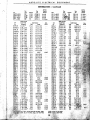
Fi.ld Current
Field Current
Test
O.E.
GFA-4802
GFA-4803
GFA-4804
GFA-4805
Spring
rest
R.t.
Tansion
Cold Output
Volts
Amps.
GAE-O 1.9-2.1"
GAG-O 4.08-4.52
GAL-O 3.51-3.89
GAM-o 3.89-4.31
GAP-O
2.85-3.15
GAR-o
3.51-3.89
GAR-2
3.70-4.10
GAR-3
3.70-4.10
GAR-4
3.75-4.15
GAR-5
3.51-3.89
GAR-6
3.51-3.89
GAS-O
3.80-4.20
GAS-l
3.80-4'.18
GBB-o
3.32-3.68~
GBE-o
"2.75-3.05¥
GBG-o
1.38-1.52'
G8J-0
4.18-4.62
3.94-4.36
3.94-4.36
4.08-4.52
3.80-4.20
3.80-4.20
3.80-4.20 '
3.80-4.20
3.80-4.20
4..1 3-4.57
4.13-457
4.18-4.62'
3.23-3.57'
3.23-3.57"
3.51-3.89
1.66-1.84
1.66-1.84 ,,"
15.0
10.5-12.5
8.0
15.0-17.0
8.0
16.0-18.0
15.5-17.5
8.0
8.0
15.0-17.0
8.0
15.0-17.0
8.0
17.0-19.0
8.0
19.0-21.6
22.4-24.4
8.0
8.0
20.4-22.4
8.0
20.5-22.5
8,0
13.3-15.3
8.0
6.6.7.6
15.0
16.0-18.0
15.0
14.0-16.0
15.0
40.0
8.0
24.0-26.0
8.0
19.0-21.0
8.0
21.0-23.0
15.5-17.5
8.0
8.0
19.0-21.0
8.0
17.0-19.0
8.0
10.0-12.0
8.0
14.0-16.0
8.0
8.0-10.0
a.o
16.0f 18.0
8.0
25.0-27.0
8.0
21.0-23.0
15.0
10.0-12.0
15,0
9.6-10.6
;'S.O
9.7-11.7
8.0
22.0
" ,8.0
14,0
~',&S'3.1 5
28.8~30.8
8.0
2.66-.2.94
8.0
20.0-22.0
1.50-1.70
.8.0
25.0
1.37-1.52' 15.0
20.0
1.66-1.84
8.0
30.0
2.3-2.4
8.0"
30.0
8,0
40.0
1.17-1.29
1.17'1.,,29
8.. 0 5 0 . 0
8.0
24.0-26.0
1.9'2.1
L9.2.1
8.0
17.0-19.0
1
1
8.0
29.0-32.0
1
8.0" 17.0-19.0
15.0
,,12.0
'15.0
8.0
8.0
15.0-17.0
8.0 ,,21.0:23.0
8.0
28.0
12.0,
8.0
15.0
15.0
~•., at 5.0 Vol~,jl!,d 165 Max. AlII"..
Lb,. af 11~ Ma~~' .(MPS. and 10.0 Volts.
Max.
Test
R.P.M.
No.
1065
1800
1380
1025
1110
1500
4010
975
1025
1500
1275
1850
1275
1565
at
6;d'vQlts
~
;;'P'id)
Cold Output
Vol..
Amps.
GCS-l
8.0
13.0-15.0
,:,,:56-3.94
GCS-5
" ,56-3.94
8.0 "19.0-21.0
, GCT-o ;:+.40-1.60* 15.0
12.0-13.0
"1.40-1.60* 15.0
GCT-l
8.0-9.0
GCW-o 1.35-1 ;50' 15.0
17.0
3.9-4.4
GCX-o
7.0
2.0
1.19-1.32* 15.0
GCY-O
33.0
1.19-1.32* 15.0
GCY-l
20.0
1.90-2.10
GCZ-o
8.0
20.0-22.0
28.0'/;
8.0
GDA-O 1.66-1.84
GDA-l
1.66-1.84
8".0
25.0
GDB-2
3.22-3.58' 15.0,,'
1.3-1.6*
GDC-O§
3.80-4.20
GDE-O
GDF-o
1.90-2.10 .
1.90-2.10
GDF-l
1.90-2.10
GDF-2
GDG-O
3.90-4.40
7.0
1.48-1.64* 15.0
GDJ-O
GDM-l 1.41-1.56'. 15.0
GDO-l
1.10-1.30
8.0 '"
1.45-1 .65 * 15.0
GDP-o
1.65-1.82
8.0
GDS-o
1.65-1.82
8.0
GDS-l
GDT-o
1.58-1.79
8.0' ""
3.5-3.9
8.0
GDU-O
GDW-o
.87- .97t 30.0
2.24-2.48' 15.0
GDY-o
GDZ-O
1.60-1.78
8.0
1.57-1.75
8.0
GEA-O
GEA-l
1..57-1.75
8.0
GEB-o
1.60-1.78
8.0
GEB-l
1.60-1.78
8.0
GEB;2
1.60-1 .78".,8.0> ", "
GEB-3
1.60-1.788.0
1.60-1.78
. 8.0
GEC-O
GED-o
1.87-2.06' 15.0
0.0
2.25-2.48
8.0
13.0-15:0
GEE-O
1.40-1.58* 15.0
GEF-o
18.0
1 .60-1. 78
8.0
',4.0.0
GEG-o
GEG:l
1.60-1.78
8.0
20.0
GEH-O
1.38-1.53' 15.0
17.0
GEH-l
1.38-1.53' 15.0
10.0
16.0 "
1.65-1.82
8.0
GEJ-o
GEK-O
2.65-2.92' 1·5.0
21
GEO-3
1.65-1.82
8.0
1
"
1.65-1
8.0
1
Max.
R.P.M.
AUTO-LITE
ELECTRICAL
EQUIPMENT
RELAYS AND REGULATORS
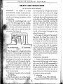
CB, CBA and RA CIRCUIT BREAKERS'
DESCRIPTION
The functian of a circuit
the voltage builds up at the generator terminal
AND FUNCTION
breaker in automotive elec-
and in the shunt coil. As soon as the voltage
trical equipment is to automatically open and
reaches the value for which the circuit breaker
close the circuit between the generator and the
is calibrated, there is sufficient magnetism created
storage battery.
by the shunt coil to pull down the armature, clos-
,
It consists of" on electromagnet and a set of
ing the contacts, automatically connecting the
contacts. The electromagnet has two windings;
generator to the battery. With the contacts thus
the shunt coil connected across the generator
closed, the current in the series coil is flowing
a voltmet~r, and the other a series coil con-
from the generator to the battery or in the same
in:sllrl~~ with the generator output like
direction as the current in the shunt coil, so that
an ammeter. (See Figure 42)
the pull on the armature is increased by magnetism of the series coil.
As the engine is stopping and the generator
loses speed, the voltage falls. As soon as the
generator voltage drops below the battery terminal voltage, the current flows fram 'he battery
to the generator, reversing the direction of current in the series coil so that the magnetism
created by the series coil is opposed to the magnetism created by the shunt coil, reducing the
magnetic pull on the armature and the spring
.en .the generator is charging the battery
~pens
current is flowing through both windings in
the contacts, disconnecting the generator
f~om the battery.
,.,.,."." ... ~,sa'11e direction. When the current flows from
battery to the generator, the current is flow-
'
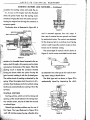
MAINTENANCE PROCEDURE
through the shunt coil in one direction and
1. Contacts-The contacts can be cleaned by
through the series coil in the opposite direction.
filing, parallel with the length of the armature,
The circuit breaker contacts consist of one
with a very fine file (ST-290 recommended) so
',m.c)vable cantact mounted on an armature oper-
that they are free from pits or burning. After
by the electro magnet, while the other is a
filing the contacts should be cleaned with refined
'?1\f,'~tc"ic>nclrv contact. These contacts are held open
carbon tetrachloride to remove any dirt or
by an" armature
spring.
The,s~.qy,en.ce-of operation
grease. Pull a piece of clean linen tape between
of the circuit br,.ak-
the contacts to remove any residue.
" . "~;~:i'~'!
ar ur;1it is,.(;i$follows:
2. Adjustments
a. Armature air gap .010 to .030 inches
:",V{h.,n the aelner·ai,,. is not rvnning, tne,.:~c)Ac'
the gener(ltor' ... :.:'
This gap is measured with the contacts closed
"
AUTO·LlTE
i:
elECTRICAL
r!
EQUIPMENT
RELAYS AND REGULATORS - Continued
I
.1
'.
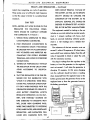
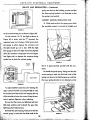
according to the temperature. The magnetic by-
Where it is necessary that the regulator be
pass is a small piete of nickel-iron across the top
checked on the car be sure that the car has stood
af the magnet core. The magnetic conductivity of
in a uniform temperature for at least 15 min-
this by-pass gradually increases as its temper-
utes. A thermometer, with its bulb placed near
ature is reduced; Thus at low temperatures much
the regulator, should be used whenever a check
of the magnetic pull of the core which would norm-
of TC regulator action is made.
ally affect the cutting in of the field resistance
The voltmeter used to check IC regulator;
flows thru this by-pass instead of the regulator
should be graduated in .1 volt readings. If the
armature and results in a higher generator volt-
test is made on the car a variable resistance
age being required to open the contacts and cut
should be connected in series in the charging
in the field resistance. On the other hand at high
circuit for proper control of the generator volt-
temperatures the magnetic conductivity of the by-
age.
pllssis reduced thus allowing the magnetic pull
1. Visual inspection
'~i'the
A visual inspection of the unit should be made
core to have full effect on the regulator
-·Ormalure and.cut in the field resistance at a lower
u
g~nerator voltage.
for:
(See Figures 45 and 46.)
a. Evidence of burning or abnormal high tem-
TC regulators have an easily accessible
peratures at the coils, contacts, insulation,
have the resistance controlling the gen-
external terminals or any other point .
. output mounted externally and a cover
b. loose connections resulting from poor sol-
which seals the working parts of the unit from
dering.
dust.
c. loose nuts on the bottom of the magnet
MAINTENANCE
When testing TC regulators
cores, loose rivets or screws. All nuts and
PROCEDURE
they should be removed from
screws must have lock washers.
the car and checked on the test bench where
2. Contacts
temperatures are known and are fairly constant.
The contacts can be cleaned by filing, parallel
COLD
HOT
=
- =----=-=--
--.
1.1
•
PART OF MAG~ETIC LII-.lES PASSING
THROUGH MAGNETIC BY - PASS
LESS PULL ON ARMATUR~
ALL OF MAGNETIC LINES PASSING
THROUGH ARMATURE NONE THROUGH
IvlAGNETIC BY-PASS MORE PULL ON ARMATURE
FIGURE 46
FIGURE 45
42
AUTO-LITE
ELECTRICAL
EQUIPMENT
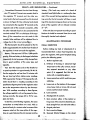
RELAYS AND REGULATORS - Continued
a
F
£
TERN. ;F"
0:''(>80# RESISTOR
FIGURE 47
with the length of the armature, with a very fine
cording to the values given in the test specifica-
file (5T-290 recommended) so that they are free
tions at the end of this section.
from pits ar burning. After filing the contacts
4. Circuit Breaker Unit
should be cleaned with refined carbon tetra-
a. Armature Air Gap-.Q1 0 to .030 inches
chloride to remove any dirt or grease. Pull a
This gap is measured with the contacts closed
piece of clean linen tape between the contacts to
and is adjusted by raising or I()wering the sta-
remove any residue.
tionary contact "A' Figure 47.
b. Contact Gap-.015 to .045
3. Carbon Resistor
Check the resistance of the carbon resistor with
an 5T-284 ohmeter. The resistance must be ac-
,"~rle•..
Adjusted by bending the. armClture .
Figure 47.
POTENTIOM ETER
3AMP 100 OHM
VOLTMETER
TERM. "A"
TERM. "F"
I
I
I
TERMINAL
!
LIGHT
CP
6-8V
FIGURE 40
AUTO-LITE
E1ECTRICAL
EQUIPMENT
RELAYS AND REGULATORS - Continued
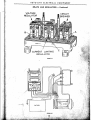
5. TC Regulator Unit
,
,
I
'
spdng by bending the lower spring holder "F"
a. Armature Air Ga~!>45
±
.001 in'i:hes
Figure 47.
This gap is measured with the regulator or con-
2. TC Regulator Operation
tacts closed. It can be adjusted by raising or low-
Connect a voltmeter as shown in Figure 49.
ering the upper contact "C" by expanding O"r'
Increase the voltage from zero and note the voltcontracting the bridge "D" holding the upper"' ""'age at which the contacts open as indicated by
contact.
the lamp dimming or going out., This voltage
b. Contact,Gap-.005 inch minimum.
figure should be within the test specifications for
Adjust by turning the brass cam "E" Figure 47.
TESTING
A~
the unit being tested and at the temperature
shown. Adjust by varying the tension of spring
ADJUSTING
"G" Figure 47 by bending the spring hanger "H".
1. Circ!!,jf Breaker Operation
" cr!,ase
t~~volfagefromzero and
,
,
Conne~t CI.Yoltmeter as shown in Figure 48. In-
Reduce the voltage and check the contact
volt~,
closing voltage as indicated by the lamp light-
by
ing. This voltage should be within thE;;test spec,l-
specifi~a:
fications shown. Adjust by turning th;ibra~$rn'
;l~;",~
:':~P"_
- '_?~';I!_,."
"E" Figare 47.lO\I'his changes the contact" gap
~~~~~,oJj;']'.Jdlust by increas-
which must not be less thqn .005 inch after
at which ,the contacts
note the
This
adlfents are completed.
TMETER
_-----..j
6V BATTERy'-....
FIGURE 49
-"-.
AUTO·LlTE
ELECTRICAL
EQUIPMENT
RELAYS AND REGULATQRS - Continued
TC REGULATOR NUMERICAL INDEX
Part No.
TC-4301A
TC·4301B
TC-4302A
TC~4302B
TC-4303A
TC-4303B
TC-4303C
TC-4303D
TC-4304A
T043i1lS8
TC-43~
TC-4a··~·
Test
Yolts
No.
Resistor*
6
6
6
1
1
1.
1
2
2
2
3
4
1
1.4
1.4
1.85.
1.1
2.85
2.85
1.85
6
TC-4~.Q5.A
TC-430SE
TC-4305F
TC-4306A
TC-4307Af
TC-430SAf
TC-4309Af
Rated
~-
12
12
12
12
6
6
6
6
6
6
6
6
6
6
6
.Fuse
'~
5
5
S
1.85
1.85
1.85
1.85
5.5
2.85
1.85
1.85
1.85
I.S5
1.85
6
6
6
1
1
4
1
1
TC-4310A
TC-4310B
TC-4311A
TC-4312A
TC-'I313A
TC-4314A
TC-4315A
TC-4316A
TC-4317A
TC-4318A
TC-4320A
TC-4320B
TC-4321A
TC-4322At
TC-4323A
TC-4323B
TC-4324A
5
5
5
5
5
5
~
5
5
5
5
5
5
5
5
5
-..lJ,.-.
5
Port No.
Rated
Volts
Test
No.
12
12
2
2
1
1
1
1
2
1
1
2
1
1
2
2
7
7
6
6
6
6
6
12
6
6
12
6
6
12
12
6
6
6
Resistor*
Fuse
2.85
1.85
1.85
1.85
1.85
1.85
2.85
1.85
1.85
5
5
5
5
5
7.5
7.5
5
5
5
7.5
7.5
5
5
5
5
5
1.85
1.1
1.85
2.85
1.85
20
7.
2.85
-).
*Ohmic re5istanc~ is the marked volue with a toterance of ± 5%.
tNo circuit breaker.
TC REGULATOR TEST DATA
TEST
CIRCUIT BREAKER
Resistance 'of Voltage Winding ... .
Armature Air Gap ....................... .
Contact Point Gap ....................... .
Point Closing Volts .................... ~•.
Point Opening Amps. Discharge ..
VOLTAGE. REGULATOR
Resisl!Jl1~e of Winding ................. .
ArmatWe Air Gap ........................ .
.. Contact' Point Gap ...................... ::· .
. High to Low Charge ................... .
. 50°F.
.. ........... .
60°F
.......................... .
70°F ........................... .
SO°F :..
..................... .
90°F
............................. .
100°F.
................., ............. .
110°F
....................... .
...................... .
Tolerance
Low to High Charge ................... .
1
2
35-39
.. 010"-.030"
.015"-.045"
6.5-7.25
111-123
. .010":,".030"
3
111-12~
13.0-14.5
.5·2.0
.01 0"-.030"
.0 15"~.045"
13.0-13.5
.5-2.0
102-112
.044" -.046"
.005" min .
102-'112"
.044"-.046"
.OQ5" min •
8.28
8.21
±.25
1.2 to 1.4
17.30
17.12
17.00
16.86"
16.70
16.56
16.42
± .40
2.4 to 2.8
15.95
IS.S0
15.65
15.50
15.35
15.20
15.05
± .20
2.0 to 2.4
± .25
'1.2'101.4
Volts below high to low
Volts below high to low
Vol~ below high to low,
VoltS~below'hI9h to low
5
6
.015"-.045"
.p-2.5
29-33
.044" ~.046"
.005" min .
S.65
a~.si"
S:50
8.43
8.35
TEST
ORCUIT BREAKER
Resistance of Voltage Winding ....................... ;~:.: ......... .
Armature Air ~p ........ ;~............................................... .
Contact Point Gap .................. ;',..................................... .
Point
Volts... ..• .
........................ .' ..... .
35-39'
.010"-.030"
.015"-.045"
6.4-7.0
':, 1.0-3.5
:' 35-39
.,.010"-.030"
.015"-.0,45"
6.4-7.0.
1.0-3.5
.034~'-.03S".
29-33
.044"-.046"
.005" min.
29-33
.047"-.049"
8.15
S.07
8.00
7.93
7.85
7.78
7.71
± .25
1.8 to 2.0
7.34
7119
7 ..25
7111
7.16
7.12
7.08
± .15
1.0 Ie, .1.2
,
.005':( min ..,
S.IS
8.07
e·OO
?/?3·
·'7:i~5
..................................., ... '.;, ........ ,.
.....................................
"'~"""'"''''
. . ::.. ,,.~/{'~?;~th Chqrge" ........••••••••••••••••............................
'7.78
. . . )',71
.± .25
f.8'to 2.0
below high to low
Volts below high to low
.OO5'~
Volts ):Ielow
min •
AUTO-LITE
ELECTRICAL
EQUIPMENT
RELAYS AND REGULATORS - Continued
"~
VRB, VRD, VRE, VRF, VRJ, VRK, VRO, VRP, VRR, VRS, VRT, VRU, VRV, VRW and VRX
REGULATORS
DESCRIPTION
While there are several types
in the generator field circuit wnich reduces the
AND FUNCTION of VR regulators they all op-
generator voltage. Immediately upon the drop-
erate on the same general principle. The follow-
ping of the voltage the contacts close, shorting
ing description of their construction and oper-
out the resistance, and the voltage rises again
ation is given so that in making the tests as out-
thus completing one cyde of operation. These
lined they may be made more intelligently.
cycles occur at frequencies necessary to maintain
The VR regulators used with third brush con-
the voltage at correct vaiues as long as the volt-
trolled generators have two units and two func-
age is high enough to keep the voltage regulator
tions to perform, namely, the closing and opening
unit in operation. With the addition of a current
of the circuit between the generator and battery
load great enough to lower the battery voltage
by means of the circuit breaker and the holding
below the operating voltage of the voltage regu-
of the voltage at a predetermined value by
lator, the contacts will remain closed and the gen-
.. /lleans of the voltage regulator unit. The current
erator will maintain its maximum charging rate .
limited by the conventional third brush action.
The voltage regulator is compensated for tem-
The. VR regulators used with shunt generators
perature variations through the use of a nickel-
three units, each performing a distinct and
iron magnetic by-pass whereby a higher voltage
'i~cle~,endent
function; 1st, the circuit breaker to
is required to vibrate the contacts under cold
and open the circuit between the generator
operating conditions than is required under hot
and
battery; 2nd,
the voltage regulator to hold
. #'
-
operating conditions. This is necessary as it re-
thi~ystem voltage at a predetermined value;
quires a higher voltage to charge a battery when
and 3rd, the current limiting regulator to control
it is cold than when it is hot.
the maximum ampere output of the generator.
CURRENT LIMITING REGULATOR UNIT
CIRCUIT BREAKER UNIT
The current limiting regulator unit used with
The operation and function of the circuit
shunt type generators has an electromagnet with
breaker unit is the same as described on page
a winding of heavy wire which is connected in
40.
series between the generator "A" terminal and
VOLTAGE REGULATOR UNIT
the series winding of the circuit breaker, so that
The electromagnet ,?f the voltage regulator
the entire output of the generator flows through
unit has a single winding which is shunt con-
it. When the generator output reaches its pre-
nected directly across the battery charging cir-
determined maximum (the ampere rating of the
·cuit. This connection is made at the circuit breaker
generator with which the regulator was designed
. . in order that the battery rather than generator
to operate), the regulator contacts are opened,
voltage win control its operation. When the vOlt-
inserting a resistance in the field circuit which
age rises to a predetermined value, this winding
reduces the ampere output of the generator. Im-
is energized sufficiently to cause the voltage regu-
mediately upon the dropping of the output the
.Iator contacts to open, thus cutting in a resistance
c
contacts dose, shorting out the resistance and the
46
AUTO-LITE
ELECTRICAL
EQUIPMENT
RELAYS AND REGULATORS - Continued
output rises completing one cycle of operation.
OPEN CIRCUIT TERMINAL VOLTAGE OF
These cycles occur at sufficiently high frequency
THE BATTERY AS WEll AS ITS SPECIFIC
so that the output is limited to a predetermined
GRAVITY SHOULD BE CHECKED. THE
maximum.
CONDITION OF THE BATTERY AS TO
CAPACITY, LEAKAGE, ETC. SHOULD BE
CAR TEST
CHECKED BY SEPARATE TEST AS SPECINOTE-BEFORE ANY WORK IS DONE ON THE
REGULATOR
THE
FOLLOWING
FIED BY THE BATTERY MANUFACTURER.
CONDI-
The equipment needed for testing on the car
TIONS SHOULD BE CAREFULLY CHECKED
includes an accurate indicating ammeter gradu-
AND CORRECTED IF AT FAULT:-
ated in 1 ampere readings with heavy short
1. WIRING FROM GENERATOR TO REGU-
leads, an accurate indicating voltmeter gradu-
LATOR PROPERLY CONNECTED.
ated in .1 volt readings and a reliable ther-
2. HIGH RESISTANCE CONNECTIONS IN
mometer.
THE CHARGING CIRCUIT. THIS SHOULD
The resistance of the test ammeter must not
BE CHECKED WITH AN ACCURATE READ-
exceed .1 volts at 10 amperes or.01 ohms.lnstru- ..
ING VOLTMETER AND INSPECTED ME-
ments which have resistance higher than this will
CHANICALLY FOR POORLY SOLDERED
make it impossible to check or adjust the
TERMINALS AND LOOSE OR CORRODED
with the necessary accuracy.
CONNECTIONS.
The drop in voltage from the regulator to
3. GENERATOR PERFORMANCE WITHOUT
battery or from the generator to the regulatot
THE REGULATOR IN THE CIRCUIT OPER-
must not exceed .1 volt when the generator is
ATING
charging 10 amperes. At this same charging
ACCORDING
TO
SPECIFICA-
TIONS.
rate the voltmeter should not show a reading
4. THAT THE REGULATOR IS THE ONE DE-
when measured from the regulator base to the
. SIGNED FOR THE GENERATOR WITH
battery ground post, the generator frame to the
WHICH IT IS OPERATING. THESE REGU-
regulator base or from the generator frame to
LATORS WILL FUNCTION SATISFACTOR-
the battery groun d post.
ILY ONLY WHEN INSTALLED WITH THE
•
GENERATOR DESIGNED TO OPERATE IT.
ALSO BATTERY CONDITION AFFECTS
• [ ,<=
REGULATOR OPERATION. AN OLD BAT-
/5'-.
.
jl'
[Iii •
0
•
15 Tr;1io
-~
WILL CAUSE HIGH CHARGING RATE;
=
WHILE ONE SUBJECTED TO EXCESSIVE
~F
SEPARATORS AND SULPHATION WILL
CAUSE LOW CHARGING RATE. THE
eATTUY
Jill
I
FIGURE 50
47
I~
)
"-2./
..;;:~F"'~
ONE SUBJECTED TO EXCESSIVE HEAT
,,~
~'
@
J
"1I'loh@
TERY, ONE PARTIALLY CHARGED OR
COLD, HARD PLATES, HIGH RESISTANCE
l .-
(,
r: !/
- "'"
.~
U
AUTO-LITE
elECTRICAL
EQUIPMENT
RELAYS AND REGULATORS ~
Continued
Connections: Disconnect the wire from the reg-
battery. (This load may consist of a bank of
Aator "B" terminal. Connect one ammeter lead to
standard head light bulbs or a carbon pile rhea-
the regulator "B" terminal and the other am-
stat.) If the current limiting regulator is function-
meter lead to the lead removed from this terminal
ing correctly, the test ammeter will show a read-
as shown in Figure 50. One voltmeter lead should
ing of the maximum amperes shown on the name
be connected to the regulator "B" terminal on the
plate of the regulator with an allowed variation
regulator side of the ammeter connection, while
of ± 5%.
the other voltmetEir lead is to be connected to the
If the unit does not operate according to speci-
terminal marked "GO" or to the,.base of the regu-
flcations it should be removed from the car and
lator.·{lf the connections are not. made in this
. thoroughly checked and adjusted.
manrier, false readings will be oflltained due to
.
MAINTENANCE PROCEDURE
.,~
. voltage loss in the current connect,'!,,,s.}
·fhe thermameter should be placed,.sa· that its
VISUAL INSPECTION
bulb Is approximately two inches from the side af
Before making any tests or adjustments it is
"the regulator. It must not touch the regulator.
recommended that a close visual inspectian be
Battery: This mU,st read 1.275 ta 1.280 specific
given the regulator, with special emphasis being
gfCl,vity,lf the car battery is discharged, substitute
paid to the following points:
. .tel1lPorarily for test purposes a fully charged bat-
1. Broken regulator seal.
tery .in good condition of the same type and
2. Evidence of burning or abnormal high
'" ·capacity.
temperature at the coils, contacts, insula-
Test: Start the engine and set the throttle for
f::
tion, external' terminals or ,.any other
a speed equivalent to approximately 30 M.P.H.
point. (It is suggested that fhis test be
Run the engine for not leu than 15 minutes with
made with a magnifying glass.)
the car hood up before taking meter readings.
3. Loose connections which result from poor
. With a generator charge of 10 amperes the volt-
soldering.
meter should show a re"ding according to the
specification figures given for the regulator under
4. Loose nuts on the bottom of the magnet
test at the temperature shown by the thermam-
cores, loose rivets or screws. 'All nuts and
eter. With readings according to these figures,
screws must have lock washen.
the voltage regulator unit can be passed as func-
5. Loose contacts.
tioning correctly. See pages 65 to 70 for com-
6. Misalignment of contacts.
plete test data.
7.' Bent armature either at the./~ontact or
To test the current limiting regulator, the same
hinge end. (The armature should be per-
connections as notet above are used. Add an
fectly straight from one end ta fhe other.)
.,electricalload ,pf a current value in excess of the
8. Magnet yoke bent.
amperes noted on the name plate of the regu-
9. Bent armature hinges.
lator at a paint between the car ammeter and the
10. Reversed bimetal hinges an the circuit
48
AUTO-LITE
ELECTRiCAL
EQUIPMENT
RELAYS AND REGULATORS -
Continued
breaker unit. (When correctly installed
rachloride to remove any dirt or grease. Pull a
the brass side must be up.)
clean piece of linen tape between the contacts to
remove any residue.
II. Stripped or crossed threads on any screw
or nut.
CARBON RESISTORS
12. Corrosion due to salt or acids.
I. Check the resistance of the carbon resis-
13. Broken ground straps.
tors. They should be removed from the regulator
14. Evidence of water having been inside of
cover.
and checked with ST-284 ohmeter. See Figure
51.
15. Incorrect, bent or distorted armature
On those regulators having more than one
spring. In case of doubt it is recommended
resistor it is extremely important that they be re-
that the spring be replaced.
placed in their proper position.
16. Broken or altered carbon resistors.
,.(.
17. Broken gaskets.
18. Incorrect wiring connections between
units.
See pages 65 to 70 for complete test data on
VR type r.agulatars.
'0
CONTACTS
Q
,0,"" " .
o
The contacts should be cleaned by filing, parallel with the length of the armature, with a very
fine file (ST-290 recommended) so that they are
free from pits or burning. After filing the contacts should be cleaned with refined carbon tet-
FIGURE 52
CIRCUIT BREAKER UNIT
2. Check resistance of circuit breaker voltage
Winding.
An accurate reading ohmeter (ST-284) is
needed for this test and is made by disconnecting
the voltage regulator lead from the circuit breaker yoke and measuring from thl! "A" terminal to
a ground on the base. Connections are shown in
Figure 52.
3. Check the armature 'air gap with the contacts open.
"Use flat gauge (ST-281-3) .034" to .038" be-
FIGURE 51
,49.,
AUTO-LITE
ELECTRICAL
RELAYS AND REGULATORS -
EQUIPMENT
Continued
it does not rub against the side of the armature.
On early production regulators the armature
stop was at the end of the armature as shown in
Figure 55. To adjust bend this stop "B" being sure
that it does not rub against the end of the arma-
'I ,
rlil l "
FIGURE 53
tween the magnet core and the armature as close
to the hinge as possible as shown in Figure 53 ..
FIGURE S6
ture. Other early regulators had the armature
stop in the center as is shown in Figure 56. On
this type bend the stop "C" being sure it does not.
e
rub against the side of the slot.
FIGURE 54
c
. Adjustment of the air gap is made by bending
•.. the armature stop "A" Figure 54 making sure that
FIGURE fil
On those applications where an indicating
lamp is used instead of an ammeter the regulator
circuit breaker unit has·a second set of contacts.
To adjust the armature air gap on this type af
unit bend the upper contact bracket "C" Figure
57 as required. BE SURE THAT THE BRACKET
FIGURE 5S.
50
AUTO·L1TE
ELECTRICAL
EQUIPMENT
RELAYS AND REGULATORS -
Continued
SUPPORTING THE UPPER CONTACT DOES NOT
contacts are perfectly aligned. This adjustment is
RUB AGAINST THE SIDE OF THE ARMATURE OR
shown in Figure 59.
TOUCH THE YOKE AND THAT THE CONTACTS
ARE ALIGNED.
VOLTAGE REGULATOR
5. Check the resistance of the winding.
An accurate reading ohmeter (ST·284) is
needed for this test. To test measure from the lead
disconnected from the circuit breaker yoke to
ground. See Figure 60 for these connections.
6. Check and see that the spring upon which
the movable contact is mounted is straight and
that it is approximately parallel with the arma·
ture.
FIGURE 58
4. Check the gap of the contacts
when open. See Figure 58.
This gap should be .015" mini·
mum, but will possibly be more than
this in actual adjustment.
Adjust by expanding or contract.
ing the bridge supporting the sta·
tionary contact, being sure that the
FIGURE 60
7. Check armature air gap.
/
FIGURE 61
Test with pin gauge. This is to be measured on
FIGURE 59
the .contact side as shown in Figure 61 apd .nel!f ..
AUTO-LITE
ElECTRICAL
EQUIPMENT
RELAYS AND REGULATORS - Continued
spring are down in the holding grooves and that
the lower spring bracket is not distorted so that
the spring is not vertical.
CURRENT LIMITING REGULATOR UNIT
B. Check and see that the spring upon which
the movable contact is mounted is straight and
FIGURE 62
to the armature stop pin aBhown in Figure 62.
To test connect a 3 C.P. test light as shown in
Figure 63 in series with the "F" terminal, the
regulator base and a battery. With the low limit
pin. gauge in place depress the armature and
the light sh~uld go out or dim. With the high
limit gauge in place the light should stay lighted
wilE'" 'the armature is depressed. Use two fingers
(see Figure 64) to depress the armature being
careful not to touch the contact spring.
FIGURE 64
3 c.P.
LAMP
o.
that it is approximately parallel with the. armature.
Re-install the spiral spring, being sure that the
correct spring is used and that both ends of the
spring are down in the holding grooves, and that
BATTERY
·0
the lower spring bracket is not distorted so that
FIG.42
FIGURE 63
To adjust slightly loosen the screw holding the
upper contact bracket and using ST-2B2 to raise
the bracket (see Figure 65) and tapping the top
of the bracket to lower tbe contact. Keep the contacts in perfect alignment when adjusting.
Be sure that the screws are tightened with suitable lock washersand..,.e;.check the gap after
tightening the bracket screws.
~E!-install
the spiral spring, being sure that the
correct spring is used and that both ends of the
fiGURE 65
52.
AUTO-LITE
ELECTRICAL
EQUIPMENT
RELAYS AND REGULATORS - Continued
the spring is not vertical.
careful not to apply pressure to the spring supporting the lower contact.
9. Check armature air gap.
Test with pin gauge. This is to be measured on
The test figures are approximate only; too
the contact side as shown in Figure 61 and next
much variation indicates wrong length to the
to the armature stop pin as shown in Figure 62.
armature stop pin and a new unit will be needed.
RE-ASSEMBlING THE REGULATOR
To test connect a test light as shown in Figure
63 in series with the "F" terminal, the regulator
When all preceding checks and adjustments
base and a battery. With the low limit pin gauge
have been completed, all the leads which have
in place depress the armature and the light
been disconnected either by the removal of a
should go out or dim. With the high limit gauge in
screw or by unsoldering should be re~connected.
place the light should stay lighted when the arm-
Where resoldering is necessary care must be
ature is depressed. Use two fingers (see Figure
taken that a good cleon contact is made. Do not
64) to depress the armature being careful not to
use acid for soldering flux.
touch the contact spring.
After the regulator has been completely re-
To adjust slightly loosen the screw holding the
assembled, its bottom should bestfllck sharply
upper contact bracket and using ST-282 to raise
on the bench several times to be sure thar~lrparts«
the bracket (see Figure 65) and tapping the top
are settled in place. Then re-check <all adjust-
of the bracket to lower the contact. Keep the con-
ments.
tacts in perfect alignment when adjusting.
TESTING AND
Be sure that the screws are tightened with suitable lock washers and re-check the gap after
LATOR WHEN TAKING
tightening the bracket screws.
WHEN THE UNIT IS BEING HEATED BY OPER.
10. Check the contact gap with the armature
ATiON PRIOR TO TAKING READINGS. THIS
against the stop< pin. (See Figure 66)
IS NECESSARY DUE TO THE FACT THAT THE
COVER FORMS PART OF THE MAGNETIC
Hold the armature down with two fingers being
FIELD AND ALSO HELPS TO RETAIN THE
HEAT.
When testing or adjusting< regulators, care ,
must be token that it is mounted firmly ahd in a
place where there is no vibration. It must also be
tested in the same position as it is mounted on the
car.
Care must be taken in making the various
test connections that these connections are firmly
made so that the resistance of all connections
does not exceed .01 ohms. <
FIGURE 66
53
AUTO-LITE
ELECTRICAL
EQUIPMENT
RelAYS AND REGULATORS -
Continued
HEAT THE REGULATOR BY OPERATING IT
FOR 15 MINUTES WITH THE GENERATOR
CHARGING 10 AMPERES. WHILE HEATING
HAVE THE COVER ON THE UNIT.
)1
1. Check circuit breaker operation.
First Method-For circuit breakers having the
upper contact mounted on a spring.
I
When making this test the voltmeter is connected between the "A" terminal of the regulator and
a ground on the regulator base. See Figure 67.
To obtain the settings increase the voltage
FIGURE 68
until the contacts close but the armature does not
and to ground. Be sure that the voltmeter con-
seal to the yoke. Take the contact closing voltage
nections are on the regulator side of the ammeter
at. this stage. Without increasing the voltage be-
connections to avoid loses due to poor connec-
yond thatcrequired to close the contacts decrease
tions. See Figure 67. When testing increase the
. the voltage until the contacts open.
voltage slowly noting the voltmeter reading just
: Second Method-For circuit breakers with the
before the contacts close. Increase the charging
upper contact mounted directly on the arm-
rate to 15 amperes then reduce the charging.
ature.
rate noting the amperage discharge just before
To test, connect an ammeter in series between
the contacts open.
the battery and the "B" terminal. The voltmeter
ADJUSTMENTS
is connected to the "A" terminal of the regulator
To adjust the closing voltage adjust the arma~IL
•ill
-··-IOl-:,..
~...
~.~;.
~'.
e
('5
~
'"
Illl,r
~
HEADPHONE
I~
I~
'
BATTERY
31
~
(if
JI
"-
-
GO.
8
~
))
fr+
,
@
r(
i~~ff·'5~
'fr.
A
[,'Q.
><rom ]
t< -"'' ' jl
....
IT(~ -
;==
.
fiGURE 67
54
,0
••
AO
I
IL
I II ~
I
if
AUrO-lITE
ELECTRICAL
EQUIPMENT
RELAYS AND REGULATORS - Continued
CIRCUIT BREAKER UNIT
LOWER SPRING BRACKETBEND DOWN TO INCREASE ='-~
CLOSING VOLTAGE-BEND
UP TO DECREASE
CLOSING VOLTAGE.
LOWER SPRING BRACKETBEND DOWN TO INCREASE
UP TO DECREASE
VOLTAGE SETTING.
CURRENT LIMITING
REGULATOR UNIT
LOWER SPRING
TO INCREASE CURRENT SETTING;:::-~;;;;"_
BEND UP TO DECREASE CURRENT SETTING.
FIGURE 69
After each adjustment replace the regulator
ture spring tension by bending the lower spring
bracket with ST-283 as shown in Figure 68. A
cover and again test the circuit
break~r
actiCln
,
very accurate method of checking this closing
2. Check voltage regulator unit.
voltage is by connecting a headphone (2000
In making this test an accurate voltmeter must
. ohms or higher) between the "S" terminal and the
be used. It is to be connected to the regulator"a"
"An terminal and taking the reading. just as the
terminal and to the regulator base as shown in
click caused by the closing of the contacts is
Figure 7l.
To adjust its operation, increase or decrease
heard. (See Figure 67, 69 and 70)
To adjust the opening voltage or amperage
the armature spring tension by bending the lower
adjust the contoct gap by raising or lowering the
spring arm with ST-283. (See Figures 69 and 70)
Replace the cover after each adjustment. Take
stationary contact.
a flash reading by stopping the generator and , .
There must always be .5 volts less voltage at
which the circuit breaker closes than the voltage
noting the moximum voltage reading when the
at which the voltage regulator operates.
generator is re-started at approximately 10 amVOLTAGE REGULATOR UNIT
LOWER SPRING BRACKETBEND DOWN TO INCREASE
VOLTAGE SETTING -BEND
":~~,II
CIRCUIT BREAKER
UNIT LOWER SPRING
BRACKET- BEND DOWN TO
INCREASE CLOSING- VOLTAGE-BEND
UP TO DECREASE .CLOSING VOLTAGE.
"
FIGURE 70
55
AUTO-LITE
ELECTRICAL
EQUIPMENT
RELAYS AND REGULATORS - Continued
The ammeter should reod within 5% of the amperage stamped on the nameplate of the regu-
,
"c:::J"
@
lator.
~,
@
If the amperage is outside the limits adjust the
,
current regulator unit by varying the spring ten-
I
sion. This is done by bending the lower spring
II
bracket with ST-283. (See Figure 69) Replace the
JI
cover after each adjustment and make a flash
IL
test.
!3ATTEIi'Y
POLARIZING
FIGURE 71
Generators should always be polarized before
running on car or bench. Do not polarize the
peres output with voltage regulator operating.
3. €heck current limiting regulator unit.
generator by holding the circuit breaker contacts
Connect the test ammeter in series between the
closed. Use a jumper from the starting switch bat-
regulator "S" terminal and the battery.
tery connection to the "A" terminal of the gener-
,,' Increase,the load on the generator by placing
ator. The excessive current in closing the circuit
a lamp bank or other suitable resistance across
breaker contact for this purpose may result in
burnt contacts.
,f/le battery on the battery side of the ammeter.
VRA, VRC, VRG, VRH AND VRY REGULATORS
DESCRIPTION
These regulators are of the
AND FUNCTION
heavy duty type. The De-
MAINTENANCE PROCEDURE
VISUAL INSPECTION
scription' and Functian and Car Test found on
Sefore making any tests or adjustments it is
pages 46 to 48 of this section is equally applic-
recommended that a close visual inspection be
able to the heavy duty type regulatars. The main
,,
given the regulator, with special emphasis being
difference is the size and the fact that on same of
paid to the following paints:
the heavy duty regulators a second winding is
used on the current limiting regulator. This sec-
1. Sroken regulatar seal.
ond winding is connected in series with the gen-
2. Evidence of burning or abnormal high
erator field circuit and is cannected so that the
temperature at the coils, contacts, insula-
rise and fall of the field current accelerates the
tion, external terminals or any other
action of the curreiit'regulator armature. This
point; (It is suggested that this test 'be ,
causes the cycles of aperation to occur at suffi-
made with a magnifying glass.)
3. Loose connections which result from poor
ciently high frequencies to limit the output ta
soldering.
minimum fluctu(1ti()~,
56
AUTO·L1TE
ELECTRICAL
EQUIPMENT
RELAYS AND REGULATORS - Continued
4. loose nuts on the bottom of the magnet
. should be cleaned with refined carbon tetra·
cores, loose rivets or screws. All nuts and
chloride to remove any dirt or greose. Pull a
screws must have lock washers.
clean piece of linen tape between the contacts to
5. Loose contacts.
remove any residue.
6. Misalignment of contacts.
CARBON RESISTORS
7. Bent armature either at the contact or
Check the resistance of the carbon resistors.
hinge end. (The armature should be per·
These resistors are found on the under side of the
fectly straight from one end to the other.)
regulator base and should be removed and
8. Magnet yoke bent.
checked one at a time in order to avoid any inter·
9. Bent armature hinges ..
changing. Use an accurate ohmeter for checking
10. Reversed bimetal hinges on the circuit
the resistance.
breaker unit. (When correctly installed
CIRCUIT BREAKER
the brass side must. be up.)
1. Check resistance of circuit breaker voltage
11. Stripped or crossed threads on any screw
•
or nut.
winding.
An accurate ohmeter is needed for this test..
12. Corrosion due to salt or acids.
This test is made by disconnecting the' voltage
13. Evidence of water having been inside of
winding ground connection and measuring from '
cover.
the lead to the stationary contact.
14. Incorrect, bent or distorted armature
2. Check the armature air gap with the con-
spring .In case of doubt it is recommended
tacts open.
that the spring be replaced.
Use flat gauge inserted on the c()ntact side of
15. Broken or altered carbon resistors.
the brass pin in the core as shown in Figure 72.
16. Broken gaskets.
17. Incorrect wiring connections between
units.
18. Shunt leads and terminal on circuit
breaker armature must be free and not
interfere with armature movement or
touch tension spring .
.See pages 65 to 70 for complete test data on
VR type regulators.
CONTACTS
The ~9I}t.acts should be cleo ned by filing, par·
allel with the length of the armature, with a very
fine file (ST.290 recommended) so that they are
free from pits or burning. After filing the contacts
FIGURE 72
57
AUTO-LITE
ELECTRICAL
EQUIPMENT
RELAYS AND REGULATORS -
Continued
3. Check gap of the contacts.
This gap should be .015" minimum, but will
possibly be more than this in actual adjustment.
(See Figure 73)
Adjust by bending the supporting arms of the
stationary contacts, being sure that both sets of
contacts are in perfect alignment and that contact is made on both sets of contacts at the same
time. Use a straight edge across the top of the
\\ \
contact brackets to check their alignment.
FIGURE 73
Adjust by raising or lowering the stop at the contact end of the armature.
a
""
FIGURE 7S
VOLTAGE REGULATOR
4. Check the resistance of the winding.
An
accu~ate
ohmeter is needed for this test. To
test disconnect both I.eads from the base and
measure between the terminals as shown in Figure 74.
.
5. Check armature air gap with contacts just
breaking.
Test with 'pin gauge as shown in Figure 75.
This measurement is to be taken on the contact·
side and next to the brass armature stop pin as
illustrated in Figure 76.
FIGURE 74
58
AUTO-LITE
ELECTRICAL
RELAYS AND REGULATORS -
EQUIPMENT
Continued
on either side of the contact spring, so that the
contact spring, is not touched. The pressure
should be applied near the center of the armature.
To adjust loosen the screws and raise or lower
the armature contact stop.
Be sure that these screws are tightened with
suitable lock washers.
Check and see that the spring upon which the.
movable contact is mounted is straight and thot 'it
is parallel with the armature.
FIGURE 76
6. Check contact gap with the armature
To test connect a 3 c.P. light as shown in Fig-
against the stop pin. Figure 78.
ure 77 in series with the "A" and "F" terminals
and a battery. With the low limit pin gauge in
place, depress the armature and the light should
go out.
With the high limit pin gauge in place,
depre.~
the armature and the light should stay lighted.
Use two fingers in depressing the armature, one
FIGURE 78
o
1;;;;lte\;;;LV
, "~"'"~.. Hold the armature down with two fingers as
jlh,strated taking care th.ot the contact spring is
~~~:rt§~-~-~-~-§~
:;;- . ~=--~~~:~~~4
...,
o
0
not touched •.
If the gap 'istpo small check to see that the
bridge
car..yi~g 'he nickel-iron shu~t has been
pushed down .in assembly. If the bridge is not
pushed down the armature rivets will strike the
shunt and prevent the contacts from opening'
--,,_.'-
3 C.P.
LAMP
BATTERY
sufficiently.
The test figures shown are approximate only;
too much variation indicates wrang ,length to
~'~~:b<_
FIGURE 77
armafure stop pin and a ney(unitWW be ne,!'dl!d•.
-
".'
~-
-,
-
'
AUTO-LITE
ELECTRICAL
EQUIPMENT
RELAYS AND REGULATORS - Continued
sure that the fibre bumper black is in place. See
Figure 80.
CURRENT LIMITING REGULATOR
8. Check the resistance of the frequency winding. An accurate ohmeter (ST-284) is needed far
this test.
FIGURE 79
;Chei:k the pressure of the contads.
"
.
:r(;tesf,
disconnect the spiral spring from
..
'~'",
i
clrmlclfjm!
cy,;C~tpIP'
the
and remove the adjustable armature
Using a spring scale as shown in Figure 79
holding the armature firm, take a reading
~s
the contacts separate.
'. N,L'
When re-assembling the armature stop, be
FIGURE 81
To test, disconnect the lead from the current
regulator unit where it is connected to the resistor
through the sub base .between the current and
voltage regulators and measure from this lead to
the current regulator yoke. See Figure 81.
When re-assembling the armature stop, be
sure that the fibre bumper block is in place. See
Figure 80.
, 9. Check the pressure of the contads.
AUTO-LITE
ELECTRICAL
EQUIPMENT
RELAYS AND REGULATORS To test, disconnect the spii'al spring from the
Continued
length to armature stop pin and a new unit will
armature and remove the adjustable armature
be needed.
stop. Using a spring scale as shown in Figure 79
RE-ASSEMBLING THE REGULATOR
and holding the armature firm, take a reading
just as the contacts separate.
When all the preceding checks and adjustments have been completed, all the leads which
When re-assembling the armature stop be sure
have been disconnected either by the removal of
that the fibre bumper I;>lock is in place. See Figure
a screw or by unsoldering should be reconnected.
80.
Where resoldering is necessary, care must be
10. Check armature air gap with the contacts
just breaking.
taken that a good clean contact is made. Do not
use acid for soldering flux.
Test with pin gauge. This is to be measured on
;t
After the regulator has been completely ..
the contact side of the brass armature stop pin as
assembled, its bottom should be struck. sharply
shown in Figure 76.
on the bench several times to be sure that an
To test connect a 3C.P. light in series with the
parts are settled in place. When doing this be sure ~
"A" and "F" terminals and a battery as illustrated
that it is struck squarely on all four mountinglug..,'
in Figure 77. With the low limit pin gauge in
Re-check all adjustments.
place depress the armature and the light should
TESTING AND ADJUSTING
go out. With the high limit pin gauge in place the
'\
.. ,
light should stay lighted. Use two fingers in de-
NOTE:-THE COVER MUST BE ON THEREGU-
pressing the armature, one on either side of the
LATOR WHEN TAKING READINGS OR WI-lEN
contact spring, so that the contact spring is not
THE UNIT IS BEING,HEATED BY OPIERA.T:{QII'I,
touched. The pressure should be applied near
PRIOR TO TAKING READINGS. THIS IS
the center of the armature.
ESSARY DUE TO THE FACT THAT THE COVER
To adjust loosen the screws and raise or lower
the armature stop.
i
~
HELPS RETAIN THE HEAT.,
When testing or adjusting regulators, care"
Be sure these screws are tightened with suitable
lock washers.
The spring upon which the movable contact Is
mounted should be straight and parallel with
",the armature.
'i"
place where there is no vibration. It must also be·
must be taken that it is mounted firmly gnd in
tested in the same position as it is mounted on the
car.
,Care must be taken in making the various tesf
11. Check contact gap" with the armature
,:'
connections that these connections are
fjrtnl~
made so that the resistance of all
does not ~xceed .01 ohms with a
charge. It is for this rea~n that spring.
nections are no! recommended. Flexible cgbleis.
which have Rat spade type ter'mil,als
nr,1>
r....." ...
AUTO-LITE
ELECTRICAL
EQUIPMENT
RELAYS AND REGULATORS - Continued
mended, as experience shows that these prevent
connections to avoid losses due to poor connec-
high resistance connections from entering into
tions. See Figure 82.
the test circuit.
To adjust the contact closing voltage adjust the
It is suggested that a single earphone (2000
armature spring tension by adjusting the screw
ohms or higher) be attached to the "F" terminal
"An Figure 83 which holds the lower end of the
and ground and used for listening to the regu-
spring. A very accurate method of checking the
lator armature vibrations and so obtain an ac-
contact closing voltage is by connecting a head-
curate indication of the operation of the current
phone (2000 ohms or higher) between the "A"
limiting and voltage regulator units.
and "S" terminals of the regulator as shown in
the regulator by operating it for 15 min-
Figure S2 and observe the voltage at which the
the ge~~rpfor charging 10 amperes.
\.vII.:I_ heating the regulator have the cover on the
click, caused by the closing of the contacts, is
heard.
To adjust the contact opening
1. Check circuit breaker operation.
, •' To test, connect the ammeter in series between
<
,#"
amperag~,
adjust the contact gap by raising or lowering the
stationary contacts.
,~
~E! ,ba'lteiY and the "B" terminal. The voltmeter
'After each adjustment, replace the regulator
~;~()nllected to the "A" terminal of the regulatar
cover and again test the circuit breaker oper-
ground. Be sure that the voltmeter connectic)n! anion the regulator side of the ammeter
BATTERY
ation.
There should always be .5 volts less voltage at
AUTO-LITE
ELECTRICAL
RELAYS AND REGULATORS -
EQUIPMENT
Continued
,
VOLTAGE
REGULATOR
CIRCUIT
BREAKER
"
A
B
CURRENT LIMITING
REGULATOR
FIGURE 83
BATTERY
FIGURE 84
AUT 0 - LI TE
E L E C T R I CAL
EQ U I PM E NT
RELAYS AND REGULATO~S ~,
Continued
which the circuit breaker closes than the voltage
the generator and noting the maximum voltage
at which the voltage regulator operates.
reading when the generator is re-started.
At the conclusion of thIs check it Is necessary
that a flnal·flash test be made.
2. Check voltage regulator unit.
3. Check current limiting regulator unit.
Connect the test ammeter in series between the
regulator "B" terminal and the battery. See Figure 84.
In making this test an accurate voltmeter must
By increasing the generator output with a lamp
be used. It is to be connected to the regulator "B"
bank
terminal and to ground. See Figure 84.
across the battery on the battery side of the am-
O~
other suitable resistance connected
adjust Its operatIon, increase or decrease
meter, the ampere output should be as noted on
lTnlatlure sprIng tensIon. Increasing the spring
the name plate of the regulator under test with
si()l~jl'c,[I,ases
the voltage at which the unit
an allowable variation of
±
5%.
'Tolpe"at1e, while decreasing the tension de-
Its~~'ration is adjusted by varying the arm-
!ts,lqpE!rol!ing voltage. This is done byad-
ature spring tension. This is done by turning the'
,screw'uB" Figure 83 which holds the
screw "C" Figure 83 which holds the' lower end
of the spring,
• • the cover after making each adjust-
It is necessary that after all adjustments are
a, flash voltage reading by stopping
made, a final flash test be made on all three units.
AUTO-LITE
ELECTRICAL
EQUIPMENT
RELAYS AND REGULATORS - Continued
NUMERICAL LIST OF VR TYPE REGULATORS
See page 68 for test specifications.
Rated
Test
Part No.
Volts
Spec.
VRA-4101A
VRA·4102A
VRA·4103A
VRB·4002A
·VRB·4002C
VRB-4002D
VRB·4003A
VRB·4004A
VRB·4004B
VRB·4004C
12
12
12
6
6
1
1
2
4t
4t
4t
4t
4t
4f
VRB·4006A
VRB·4007A
VRB"4007B
VRB·4008A
6
6
6
6
6
6
Ground
. Polarity
Rl
Positive
135.
135
135
60
60
60
30
60
30
60
Positive
Positive
Positive
Positive
Positive
Positive
p'ositive
Positive
Positive
15
15
15
R4
.65
.65
.65
......
11
7
Positive
Negative
Negbtive
Positive
6
6
4t
4
4
4
Positive
Positive
Positive
Positive
6
6
6"
6
4
4
4 •
4
Positive
Negative
6
6
6.
6
6
4
5
6
Carbon Resistors·
R2
R3
I
VRB.4010A
VRB:4011A
VRB-4011B
VRB-4012A
. VRB-4012A-l
VRB-4012B·l
VRCc4i·01A
•
f
;,'t'
6
6
B
VRD"4002A
VRD-4002B
6
6
(
6
6
6.6
6
6
6
6
12
30
60
30
Negative
Positive
38
80
BO
80
BO
20
20
20
20
Positive
5
5
Positive
5
4t
4t
4t
Positive
Positive
Positive
Positiyf;t
Positive."
Positive
i
Positive
6t
4t
4t
4
20
20
20
20
Negative
Positive
8
Positive
4t
4
9
Positive
•
30
20
20
60
Positive
Positive
......
VRE·4001C
VRE-4002A
VRE·4002B
VRE-4002C
•
VRE·40GSK"""-"
VRE-4003A-l .
VRE-4004A .
VRE-4005A
resistance is the
.serici)·,,",umber
12
12
12
12
12
12
12
12
12
Positive
9
9
9
9
60
60
60
60
Positive
.:~'
"
P!)sitive '
P'O~itive
60
60
60
60
,Po~itive
' ':P6s;'tive .
'r· •• '
;p~'sitive
",um~er
20
8R-OOQOOl 'set,!9
Operating
Amperage
19·21
39·41
19·21
29·31
24-26
AUTO.L1TE
ELECTRICAL
EQUIPM¥T
--o;;r.;:..
RELAYS AND REGULATORS ~
Rated
Part No.
VRF·4Q01A
.·VRF·4Q03A
.VRF·4004A
VRF·4005A
. VRF·4006A
VRF·4007A
lA
Volts
12
12
12
12
12
12
12
12
12
12
Test
Spec.
Ground
9
9
9
9
9
Positiv;~
Positive
Positive
Polarity
Positive
Positive
Continued
.,
.- Carbon Resistors·
.2
R3
Operating
Amperag.
30
30
30
30
30
Positive
Positive
Positive
31·34
31·34
19·21
Negative
Positive
Negative
Jo.,I~g,Q,tiy~
\Positl~e
. Negative
Positive
80
80
60
60
15
15
11
11
30
30
........
54-56
54·56
39·41
39·41
60
20
7
15§
Positive
30
7
29·31
34-36
31·33
27·29
Positive
60
11
15§
7
7
24-26
39-41
34·36
27·29
Positive
Positive
Positive
Positive
~Positive
60
38
60
60
3S
30
Positive...
Positive' Positive
Positive
60
38
38
'Positive
Positive:
60
38
·38
38
38
60
60
15§
7
7
7
7
7
15§
11
60
60
15
60
11
11
60
11
AUTO·lITE
ELECTRICAL
EQUIPMENT
RELAYS AND REGULATORS - Continued
Part No.
VRP·4009B
VRP·4009C
VRP·4009D
YRP.4010A
:VRP·41Q1A
VRP.4102A
VRP·4103A
VRP:4104A
_VRP.41048
VRP4105A
VRP'420 I A.I
.I
Rated
Volts
6
6
6
6
6
6
6
6
6
6
6
6
6
6
6
Tes'
Spec.
12
12
12
12
12
12
12
12
12
12
Ground
Polarity
Negative
Negative
Negative
Positive
Positive
Positive
Positive
Negative
Negative
Positive
Positive
Positive
Positive
Positive
Positive
Negative
. Positive
Positive
Positive
Positive
Positive
... Po_s!tiv~
Carbon Reliston·
RI
30
60
30
60
30
3Q,
60
60
60
60
38
38
30
20
R2
7
R3
Operating
Amperas.&
27·29
15§
3941
7
24-26
15
31·33
21·23.
21·23
19·21
19·21
19·21
19·21
34·36
11
11
30
30
7
7
...
AUTO-LITE
ELECTRICAL
EQUIPMENT
RELAYS AND REGULATORS - Continued
VR REGULATOR TEST SPECIFICATIONS
TEST
CIRCUIT BREAKER
Res. of Voltage Winding ......
. Ar.mafure Air GapL
,Confact Point Gap ..................... ..
Points Close (Volts) .. .
Points Open (Amps.) ................. .
1
2
3
4
49.7
.055"-.062"
.015" min.
13.0-13.5
.5-4.0
49.7
.055"-.062"
.015" min.
13.0-13.5
.5-4.0
35-39
_034"-_038"
_015" min_
. 6.4-7.0
.5-3.0
35-39
_034"-_038"
_015" min _
6.4-7.0
.5-3.0
15.7-i7.3
.040"-.042"
.010"- min.
15.7-17.3
.040"·.042"
,OlD" min.
12.8-14.3
.0595"-.0625"
.010"-.020"
10.4-11.2
.0595"-.0625"
.010"-.020"
7.68
7.66
.7.65
7.63
7.62
7.61
7.60
7.59
± .•15
7..51
7.48
7;45
REGULATOR
14.51
14.48
14.45
14.42
14.39
14.36··
14.33
14.30
±.15
.018
"'-;-'c.""'~"""-:,~··········
,~-
.
,
14.31
14.28
, 14.25
14.22 '.
14.19
14.16
14.13
14.10 .
.± .. 15 .
-
,,'
.\;,.
"
c_:;",
.0111·····
,047"-.049" ',2."_::1\'
',iJI.' ······047".049"
•
.010" min.'"
.010" min.
.'
5
.
.0595"-.0625".
.01O'i..020"
"~;!,!:t!
7
6
,
15.8-17.4
.055"-.062"
.015" min •..
6.5-7.0
.5-4.0
4.3'4;7
.040"-.042"
-,,/ .010" min.
7;51 .
7:48
7.45
7;42
7.:},?
, 7.36
7.33
7.30
± ;15
35-39
.034"'-.038"
•015" min •
6.4-7.0
.5-3.0
10..4-}1.2' .
. .0595",.l)625"·
.Q1 Qr~ :.()20'~
"7.63
7.56
7.50
7.43
,7,37
7.30
7.24
7.17
.• 15
-,
'0'
35~39.
.034"-.038'"
~iJi5"- min,•
6;4-7.0'
.<.5,3.0 •
",
12.8-1.,4.3
1.0.4,:)1.2
.0595"-.0625"•• " . "0,5?5"" 0625" .
..01 0"~iC)20",l.·:jjfO'(920"
,
.
.7.98
7.96
7.95
7 ..93
7.92
7.91
. 7.89
" 7.§8 .
± .15,
.,
....,'.;'
. ,
..
:-'! '
ELEC'YRICAL
AUTO-UTE
:"
-
EQUIPMENT
RELAYS AND REGULATORS - Continued
TEST
CIRCUIT BREAKER
Res. of Voltage Winding ............. .
Armature Air Gap~ ..................... .
Contael Point G!lp ............ ,.......... .
Points Clo~e (Volts) ............. w.... ..
Points Open (Amps,). ............ , ..... .
Points Opeil(Volts)................ :.... .
".
VOLTAGE REGULATOR
Res. of Winding ..
Armature Air Gap ....................... .
'Contael Point Gap ........ ,,; ..
Operatinl! Voltage
'SO°F' ................................ .
60°F
..................... .
70°F
.......................... .
BO°F
.......... :.•~ ........ .
9
10
11
12
111-123
.034"-.038"
.015" min.
13.0-13.75
.5-3.0
49.7
.060"-.065"
.015" min.
13.0-13.5
.5-4.0
345
.034"-.038"
.015" min .
25.0-25.75
,5-2.0 ."
29.8-33.0
.031"-,034')
.ots"· min.
6.4-6.6
45.B-49.6 .
15.7-17.3
.040"-.042"
.010'~ min.
191-209
.0595"-.0625"
.010"-.020"
.0595"-.0625"
.010"-.020"
:~:~~
14.59·
14.54
14.50
14.46
14.42
14.37
14.33
14.28
.± ;t5
"14.45
14.42
14.39
•14.36
14.33
14.30
± ,15
.047"-.049"
.010" min.
14
.~ 29.6,33.0
..03J," ••034"
, .Oi5"min.
, 6.4.:6.6'
'j'~'lt~~;ts:6
\10.8-12.Q
.048"-.052"
.012" ",In;"
. 7'6~3:'.
'7:~~
·7;43
','
7;38 .
7.31
-~f>
'<.>{~c-c
• 7/}:4
7,11,
::1;'.15
.04a",-.OS2"t
..012" min'.
.± .•15
27.B4
27,67
27.50
27.33
27.16
26.99' .
AUTO-LITE
ELECTRICAL
EQUIPMENT
RELAYS AND REGULATORS - Continued
TEST
~,
.IRCUIT BREAKER
Res. of Voltage Winding ............................................................................ ..
Armature Air Gapt ......................................................................................... .
Contact Point Gap ........................................................................................ .
Points Close (Volts) ........................................................................................ ..
Points Open (Amps.) ...................................................................................... ..
~-,:
.-.'
VOLTAGE REGULATOR
Res. of Winding ............................................................................................ ..
Armature Air Gap ......................................................................................... .
Contact Point Gap .......................................................................................... .
Operating Voltage
50°F ........................................................................................................ ..
60°F
.............................................................................................. ..
70°F ..
............................................................................................... ..
80°F .
................................................................................................ .
90°F .........................................................................................................
100°F ......................................................................................................... .
.110°F ......................................................................................................... ..
"'120°F ........................................................................................................ ..
.Tolerance ................................................................................................... .
17
18
15.8-17.4
.0595"-.0625"
.015" min.
6.5-6.6
0.5·4.0
49.7
.060"...065"
.015" min.
13.0·13.5
0.5--4.0
4.3-4.7
.040"-.042"
.010" min.
15.7-17.3
.0465"-.0495"
.010" min.
7.41
7.38
7.35
7.32
7.29
7.26
7.23
7.20
± .15
14.31
14.28
14.25
14.22
14.19
14.16
14.13
14.10
± .15
.033-.037
.047"-.049"
.010" min.
.0465"-.0495"
.010" min.
;:,,+'KKt:NT REGULATOR
'Cc
of ,Frequency Winding ..............................................................................
,'rn,al'lII'8 Air Gap ......................................................................................... .
Conlact Poinl Gap.......................................................................................... ..
70·
,
AUTO-LITE
ELECTRICAL
EQUIPMENT
STARTING MOTORS AND SWITCHES
DESCRIPTION AND FUNCTiON
The starting motor is designed to crank the
engine when the starting switch closes the circuit
between the storage battery and the motor. The
design of the starting motor depends upon the
type and application of the engine on which it is
to be used. Starting motors vary as to size, number of poles and number of brushes.
MOTOR DRIVES
FIGURE 87
To transmit power to the flywheel of the en-
In either case the action of the clutch is identical.
gine Auto-lite starting motors use either an over-
Figure 88 illustrates a typical overrunning ukoh,'
running clutch or a Bendix drive. Some motors
The clutch has internal splines to match the "
have a gear reduction between the armature
and drive pin ian to increase the power for heavy
on the armature shaft. When the yoke '''''.",.•
shifted, either mechanicolly or eleicfr'icaIlY:'
duty ,installations. (See Figure 85).
complete drive is moved along the armature shalt;'
d,
JI'
-:', -':-,
FIGURE 85
The over~unning clutch pinion may be shifted
until the pinion meshes with the flywheel ring
either mechanically through a starter pedal (Fig-
gear. If the pinion teeth do not mesh with the
ure 86) or electrically by a solenoid (Figure 87).
flywheel teeth the movement of the yoke arm is
taken Up by the spring. When the switch contacts
close the armature rotates allOWing the spring
FIGIIIIE 88
FIGURE 86
71
tov
AUTO-LITE
ELECTRICAL
EQUIPMENT
STARTING MOTORS AND SWITCHES -
Continued
complete the meshing action and crank the en,~
ne. As soon as the engine starts the flywheel
drives the pinion faster than the starting motor
armature bringing the clutch into action and preventing the engine from driving the armature at
excessive speeds.
The Bendix drive is illustrated in Figure 89. It
FIGURE 90
and is mounted separate from the motor. It
has a set of contacts that are opened and closed
by mechanical action. The contacts are designed
for the large currents in a starting circuit. Spring
action is used to open the contacts to give a clean
break and to minimize arcing.
The second type of manual switch is shown in
Figure 91 and is remote controlled from the dash
FIGURE 89
consists of a threaded sleeve fastened to the armature shaft through a drive spring and a pinion
mounted on the threads of the sleeve. When the
~iarting circuit is closed the armature revolves
FIGURE 91
turning the sleeve within the pinion forcing the
by a Bowden wire. This type is also used on start-
gear forward meshing it with the flywheel gear.
ing motors using a Bendix drive.
,,'
The sudden shock of meshing is absorbed by the
The third type such as shown in Figure 92 is
spring. When the engine starts the pinion is driv-
mechanically closed by depressing the clutch
en faster than the sleeve and is forced bock along
the threads automatically de-meshing it from the
flywheel.
STARTING SWITCHES
Starting switches, which control the closing and
opening of the circuit between the storage battery and the motor, may be of either the manual
or solenoid type.
Manual type starting switches may be one of
four. types. The type illustrated in Figure 90 is
used with starting motors having a Bendix drive
FIGURE 92
72
AUTO-LITE
ElECTRICAL
EQUIPMENT
STARTING MOTORS AND SWITCHES -
Continued
pedal and has a vacuum release and vacuum release lock to prevent operation of the starting
motor when the clutch pedal is depressed while
the engine is running. With the engine not run\ TERt1,W"L pos 7
ning depressing the clutch pedal closes the startig switch thru cam "A," latch "B" and pressure arm
"C." When the engine starts the latch "B" is lifted
thru a connection to the vacuum diaphragm
so that it disengages with the cam and the switch
is opened by spring action. As long as the engine
continues to run the latch is held in the disen-
~P"UN,C;ER
SPRING
gaged position so that the clutch pedal can be
operated without closing the switch.
--I'-1""Ne"TIC COIL.
The last type such as shown mounted on the
motor illustrated in Figure 86 is used only on
FIGURE 93
motors with overrunning clutches. It is controlled
The first of these types is shown in Figure 93
by a foot pedal that is connected by linkage to
and is used with Bendix drive motors. It magnet-
the shift yoke which moves the clutch pinion into
ically closes the circuit between the storage bat-
mesh and then closes the switch contacts.
tery and the motor and is controlled by a push
Solenoid starting switches may be divided into
button located on the instrument panel.
two types: those which magnetically dose the
starting circuit and those which not only close the
The second type not only magnetically closes
starting circuit but also shift the overrunning
the starting circuit but it also shifts the overrun"
clutch pinion.
ning clutch pinion into mesh with the flywheel
TO
STARTER
~7;:::r::;~,"","J."t:=--' GROU~ID
FIGURE 94
73
TO SWITCH COVER
AUTO-LITE
ELECTRICAL
EQUIPMENT
STARTING MOTORS AND SWITCHES -
Continued
gear. It is controlled by a push button, mounted
and the main switch is closed both windings have
the instrument panel, thru a relay mounted
current flowing thru them causing the solenoid to
,~
<l"
exert its strongest magnetic pull on the plunger
within the switch. (See Figure 94).
The solenoid coil includes two windings; a
thus assuring positive meshing of the pinion.
series winding connected from the relay station-
When the main switch contacts close the series
,
ary contact to the main switch terminal connect-
winding is short circuited and the plunger is held
ing with the starter motor and a shunt winding
in place by the shunt winding only. This results in
connected from the relay stationary contact to
a minimum amount of arcing at the relay contacts
ground. Between the time the relay contacts close
when the switch opens.
MAINTENANCE PROCEDURE
of a good grade of S.A.E. No. 20 oil added each
A periodic inspection should be made of the
5000 miles.
starting circuit. While the interval between these
checks will vary accordng to the type of service
STARTING MOTOR OVERHAUL
it should, under normal conditions, be made
At intervals of approximately 25,000 miles the
every 5000 miles. At this check the following
starting motor circuit should be thoroughly
points should be inspected.
checked and the motor removed from the car for
1. Wiring
cleaning and checking.
A visual inspection should be made of all wires
1. Starting Circuit
to be sure that none are broken and that all
The starting circuit should be inspected to be
connections are clean and tight.
sure all connections are clean and tight and that
2. Commutator
the insulation on the wires is not worn or dam-
If the commutator is dirty or discolored it can
aged. The starting circuit should be given a
be cleaned with 00 sandpaper. Blow the sand
voltage loss test to make sure there is no loss of
out of the motor after cleaning.
starting motor efficiency due to high resistance
Should the commutator be ro'ugh or worn the
connections. (See Figure 95) In making this check
motor should be removed from the egine for
the voltage loss from the battery terminal to the
cleaning and reconditioning. Instructions for the
starting motor terminal should not exceed .12
servicing of starting motors are given later in this
volts maximum for each 100 amperes. The loss in
section.
voltage between the battery ground post and the
3. Brushes
starting motodrame should not exceed .12 volts
The brushes should slide or swing freely in
maximum for each 100 amperes. If the voltage
their holders and make-full contact on the com-
loss is greater than the above limits the voltage
mutator. Worn brushes should be replaced.
should be measured over each part of the circuit
4. Lubrication
to locate the resistance causing voltage loss.
Motors having oilers should have 5 to 10 drops
When measuring the voltage loss across solenoid
74
AUTO-LITE
ELECTRICAL
EQUIPMENT
STARTING MOTORS AND SWITCHES - Continued
CONNECTIONS
2-RESISTANCE OF CABLE C0NNECTIONS
I - RESISTANCE OF GROUND CONNECTIONS
---------- -.,
,i .
STARTING
MOTOR
,...I-,.,_'Q. . .~ - -
... IC--\:--
~
-
- -,
PI
I
+
I
BATTERY
500
FIGURE
AMPERE
SHUNT
1000 WATT
CARBON PILE
9~
switches the contacts should be closed electric-
condition. The ormature, field coils and brushes
ally to simulate actual conditions of operation.
should be checked for grounds ·or open circ':;its.
2. Brushes
DISASSEMBLY
The brushes should slide or swing freely, in
To remove the starting motor from the car dis-
their holders and make full contact on the com-
connect the leads and cover the battery lead
mutator. Worn brushes should be replaced.
with a short piece of hose to prevent short cir-
When replacing brushes that have the lead
cuiting. Take out the flange bolts holding the
riveted to the brush holder the rivet should be
motor to the flywheel housing. The motor will then
removed and the new rivet should be securely
lift off and can be taken to the bench for a com-
staked to make sure the brush .holder is solid and
plete overhaul.
that the lead makes a good ground cantatt.
When disassembling the motor each part
Brushes that are soldered to the field coil lead
should be removed a!ld cleaned and inspected
should be unsoldered and have the loop in the
for wear or damage. The Bendix drive or over-
field coil lead opened. The new brush pigtail
running dutdHhould be cleaned and inspected
should be inserted to its full depth in the loop and ..
for wear and for a distorted spring. Bearings
then clinched before resoldering. A good solder"
should be checked for proper clearance and fit.
ing job must be done to insure no loss of starting
A" insulation should be free from oil and in good
motor efficiency due to a poor contact.
75
AUTO-LITE
ELECTRICAL
EQUIPMENT
STARTING MOTORS AND SWITCHES Brush spring tension should be checked with a
Continued
use a set of test probes such as illustrated in Fig-
spring scale. See specifications on page 81. To
ure 96.
check the tension on swinging type brushes hook
the scale under the brush screw tight against the
brush and exert the pull in a line parallel to the
side of the brush. Take the reading just as the
T~ST
POINTS
brush leaves the commutator. When checking the
tension of reaction ,type brush springs hook the
scale under the brush spring near the brush and
pull on a line parallel with the side of the brush.
FIGURE 96
Take the reading just as the spring leaves the
'0
brush.
point to a commutator segment and touch the
If the brush spring tension is too low there will
core or shaft with the other probe. Do not touch
be a loss of efficiency due to poor brush contact.
the points to the bearing surface or to the brush
If the tension is too great the commutator and
surface as the arc formed will b"rn the smooth
brushes will wear excessively and have short life.
fi~ish.
It is therefore important that the. brush spring
If the lamp lights, the coil connected to the
commutator segment is grounded.
tension be kept within the limits specified. To
To test for shorted armature coils a growler is
change reaction type spring tension twist the
necessary. The armature is placed against the
spring holder with long nosed pliers. On swing-
STEEL STRIP HELD ON
ARMATURE SLOT
ing type brush holders it is necessary to remove
'me
test the armature for grounds touch one
spring and arm, and bend the spring to
change the tension.
3. Commutator
Check the commutator for wear or discoloration. If the commutator is only slightly dirty or
discolored it can be cleaned with 00 ar 000
sandpaper. Blow the sand out of the motor after
cleaning the commutator. If the commutator is
rough or worn the armature should be removed
and the commutator turned down in a lathe.
4. Armature
The armature shovld·be visually inspected for
mechanical defects before being checked for
shorted or grounded coils.
For testing armature circuits it is advisable to
76
AUTO-LITE
ELECTRICAL
EQUIPMENT
STARTING MOTORS AND SWITCHES - Continued
core and a steel strip held on the armature. The
and turn the armature slowly in the direction of
armature is then rotated slowly by hand. If a
rotation. Blow the sand and carbon dust out of
shorted coil is present the steel strip will become
the motor after sanding.
magnetized and vibrate. This test is illustrated in
When installing the yoke and overrunning
Figure 97.
clutch the yoke shoes should be assembled with
5. Field Coils
the radial side toward the pinion end of the
Using the test probes illustrated in Figure 96
clutch.
check the field coils for both opens and grounds.
8. lubrication
To test for grounds place one probe on the motor
Auto-Lite starting motors are equipped with
frame or pole piece and touch the other probe to
absorbent bronze bearings. These bearings are
the field coil terminals. If a ground is present the
able to absorb 25% of their own volume in oil.
lamp will light.
Most of the drive end and intermediate bear-
Ta test for open circuits place the probes on
ings do not need any attention. The
commutato~
the field coil terminals across each coil separate-
end bearing and some of the intermediate bear-
ly. If the light does not light the coil is open
ings are equipped with oilers which should be
circuited.
given 5 to 10 drops of medium engine oil every
6. Brush Holder Inspection
5000 miles. Do not over lubricate as excessive
Using the test probes illustrated in Figure 96
lubrication will damage commutators and insulation.
touch the insulated brush holder with one probe
and a convenient ground on the C.E. plate with
Gear reduction motors have a grease pocket
the other probe. If the lamp lights it indicates a
in the gear chamber which should be filled with
grounded brush holder.
a high melting point grease when assembling. If
7. Assembly of Motor
this gear reduction is provided with a grease cup
When assembling absorbent bronze bearings
it should be given one turn every 5000 miles. If an
always use the proper arbor as these arbors are
oiler is provided it should be given 5 to 10 drops
designed to give the proper bearing fit. Soak
of medium engine oil every 5000 miles.
When the starting motor is serviced the bear-
the bearing in oil before assembling in the bear-
ings should be soaked in oil and the bearing seats
ing bore.
should be given a light wipe of oil.
The pinion end of the armature shaft should be
given a light wipe with very light oil when
9. Bench Test
assembling.
Tlie motor should first be checked to see that
Brushes should be correctly installed and con-
the free running voltage and current are within
nected as previously outlined in order to be sure
specifications. (See page 81 for test data.) To test
proper~,sf<'rting
motor efficiency. Proper brush
connect the motor to a battery and voltmeter
seating should be insured by sanding the brushes
as in Figure 9B. If the current is too high check
to fit the commutator. To sand the brushes wrap
the bearing alignment and end play to make
a strip of 00 sandpaper around the commutator
sure there is no binding or interference.
of
77
AUTO-LITE
ELECTRICAL
EQUIPMENT
STARTING MOTORS AND SWITCHES - Continued
[
500 AMP. SHUNT
1000 WATT
CARBON
PILE
o
BATTERY
"'--vc,Ln.. TER
CONNECTIONS
FIGURE 98
Using a spring scale and torque arm as shown
The Bendix or clutch should be checked for cor-
in Figure 99 check the stall torque to see that the
rect operation. The Bendix pinion should be
motor is producing its rated cranking power.
checked to see that it shifts when the motor is
The stall torque will be the product of the spring
operated under no load. The overrunning clutch
scale reading and the length of the arm in feet.
should be inspected for proper clearance when
. If the torque is not up to specifications check the
in the free running position. This clearance should
seating of the brushes on the commutator and
be 5164"
the internal connection of the motor for high
pinion and the thrust washer next to the outer
resistance. (See page 81 for test data.)
pinion housing bearing as shown in Figure 100.
±
1164" between the outer edge of the
500 AMP. SHUNT
1000 WATT
CA~80N
PILt
TORQUE
TEST
."
8ATTERY
50 POUNO
SPRING
L -______~J
~~
~
SCALE
X
PULL HERE
FIGURE 99
78
VOLTMETER
CONNECTIONS
AUTO-LITE
ELECTRICAL
EQUIPMENT
STARTING MOTORS AND SWITCHES -
Continued
To check this clearance shift the pinion by apply-
tacts closed by ehergizing the switch to approxi-
ing pressure to the yoke arm on the positive shift
mate the actual conditions of operation.
type or by applying pressure to the plunger of the
TEST SPECIFICATIONS
solenoid switch on the magnetic gear shift type.
i
Amperes Draw
6 volt units--2.9 to 3.3 amperes at 6 volts.
PI.'IIO/V HOUSINt:i
12 volt units--1.47 to 1.57 amperes at 12 volts.
Switch Contacts Close
6 volt units-4 to 5 volts
12 volt units-8 volts maximum
Switch Contacts Open
6 volt units-.5 to 2.0 volts
12 volt units-1.5 to 4.0 volts
55-4100, 55-4200 and 55-4700 SWITCHES
The relay contacts when open should have .025
FIGURE 100
inch minimum to .035 inch maximum gap.
To adjust the clearance, screw the starting switch
Before making any tests on the switch make'
plunger in or out on the positive shift starting
sure that cilliinkage operates freely with no bind-
motors or adjust the plunger screw on the mag-
ing and that the switch plunger can be bottomed'
netic shift starting motors.
in the solenoid without drag or restriction. When
under test the plunger should bottom' instantly
STARTING SWITCH TESTS
without chattering.
MANUAL. SWITCHES
This type of switch can best be tested by com-
TEST SPECIFICATIONS
paring voltage readings between the terminal
55-4100-6 volt units
connected to the battery and the terminal
connected to the starting motor. A maximum vari-
Relay
ation not in excess of .05 volts per 100 amperes
Contacts close 3.5 to 4.5 volts
is allowed. A greater variation indicates poor
Contacts open 1.5 to 2.5 volts
Solenoid
switch contacts. Switch contacts should be filed
Shunt coil only 14 to 16 amperes at 6.0 volts
for full surface contact or the complete switch
Shunt and series 34 to 38 amperes at 3.0 volts
replaced.
55-4100-12 volt units
55-4000 SERIES SWITCHES
Relay
This type switch should be checked to see that
Contacts close 7.0 to 9.0 volts
the opening and closing voltages are within limits
Contact. open 3.0 to 5.0 volts
and that the voltage loss across the main contacts
Solenoid
is not in excess of .05 volts per 100 amperes.
Shunt coil only 5.0 to 6.0 amperes at 12.0 volts
When checking this voltage loss have the con-
Shunt and series 22:0 to 26.0 amperes at 6.0 volts
79
AUTO-LITE
ELECTRICAL
EQUIPMENT
STARTING MOTORS AND SWITCHES - Continued
55-4700-6 volt units
55-4200-6 volt units
~
Relay
Relay
Contacts close 3.5 to 4.5 volts
Contacts close 3.5 to 4.5 volts
Contacts open 1.5 to 2.5 volts
Contacts open 1.5 to 2.5 volts
Solenoid
Solenoid
Shunt coil only 7.0 to 8.0 amperes at 3.0 volts
Shunt coil only 7.0 to 8.0 amperes at 3.0 volts
Series coil only 27.0 to 30.0 amperes at 3.0 volts
Series coil only 38.0 to 42.0 amperes at 3.0 volts
55-4200--12 volt units
Relay
Contacts close 7.0 to 9.0 volts
Contacts open 3.0 to 5.0 volts
Solenoid
Shunt coil only 1.8 to 2.2 amperes at 5.0 volts
Series coil only 15.5 to 18.5 amperes at 5.0 volts
I
80
"'-,;.,.,
,"""
",::,:,~:...,<u,,,;-",,,,,,
"',
i."_,jo'~·"_,.,;,,,,
'-;~"'"'_
.; ;,,,
i ~
~>"'>R/(''''
'
AUTO-LITE
ELECTRICAL EQUIPMENT
STARTING MOTORS AND SWITCHES - Continued
STARTING MOTOR TEST SPECIFICATIONS
Gear
Type
Volts
01
01
6
12
6
6
6
6
6
6
6
6
6
12
12
12
12
6
6
6
6
12
12
6
6
11
24
12
12
12
12
6
12
6
6
6
6
12
6
12
ON
OY
MAB
MAO
MAJ
MAK
MAL
MAO
MAP
MAR
MAS
MAU
MAU
MAW
MAX
MAX
MAX
MAY
MAY
MBA
MBB
MBC
MBO
MBE
M8E
MBF
MBG
MBH
MBJ
MBK
MBl
MBM
Ml
Ml
MR
MR
MZ
MZ
"6-
12
Ratio
Spring
Tension
Ounces
56-60
56-60
56-60
36-40
42-53
42-53
42-53
38-61
42-53
24-32
2:1
22:14
29:14
29:14
2:1
12-16
42-53
42-53
42-53
42-53
42-53
42-53
42-53
42-53
42-53
40-50
38-61
38-61
42-53
12-16
12-16
12-16
12-16
42-53
42-53
No Load
Amps.
Volts
Min. RPM
Volts
Stall Test
Amps.
3.6
6.0
3.6
3.5
4.0
4.0
4.0
4.0
4.0
4.0
730
410
810
720
775
730
750
520
825
975
29.2
16.6
39.0
29.4
22.5'
18.5
17.0
7.0
32.0
48.5·
.
6.0
6.0
6.0
4.0
4.0
4.0
4.0
6.0
6.0
4.0
440
540
535
670
880
845
906
285
260
700
20.0
17.3
35.0
18.0"
25.0
6.0
6.0
6.0
5.0
6.0
4.0
6.0
590
300
300
135
375
500
570
35
3.&
8.4
6.0
9.8
12.0 .
18.0.
4.0
4.0
4.0
4.0
4.0
4.0
4.0
6.0
420
420
750
750
700
700
560
375
5.0
5.0:.
26.0· '.
26.0
43.0
43.0
6.0
60
4500
6.0
6.0
5.5
5.5
5.5
5.5
5.5
5.5
5.5
11.0
11.0
11.0
11.0
5.5
5.5
5.5
5.5
11.0
11.0
5.5
5.5
5.5
22.0
H.O
11.0
10.0
11.0
5.0
11.0
5.0
5.5
5.5
5.5
5.5
5.5
11.0
5.5
11.0
50
50
60
60
67
70
50
44
41
45
35
65
65
65
65
70
77
30
42
65
60
35
70
3000
3000
3700
3600
4100
5000
3200
2700
9000
10000
4100
4800
2500
4900
5300
3900
2695
5300
2500
4500
10000
10000
5800
6200
3500
4800
7300
6000
6400
11000
5000
5000
2980
2980
2800
4300
4300
7300
22
55
40
65
65
60
60
50
50"
40
50
70
. . 55
Min. Ft. Lbs.
n.s
9.S .
~"
81
."