1
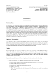
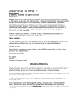
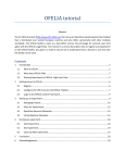
User Manual
Robotdog, Group 4
December 14, 2012
Project Identity
Group 4, 2012/HT, "The Robot Dog"
Linköping University, ISY
Name
Responsibility
Phone number E-mail
Martin Danelljan
Design
072-372 6364
[email protected]
Marcus Eriksson
PR
073-647 7180
[email protected]
Daniel Hultqvist
Project manager 070-289 2859
[email protected]
Victor Johansson
Test
072-500 8006
[email protected]
Johannes Markström Documents
070-353 9655
[email protected]
Niklas Pettersson
076-634 2903
[email protected]
Customer:
Course
Quality
Michael Felsberg, [email protected], CVL, LiU
examiner: Vasileios Zografos, [email protected], CVL, LiU
Supervisor: Liam Ellis, [email protected], CVL, LiU
Contents
1
2
User Manual
1.1
1.2
1.3
1.4
Connecting the hardware . . . . . . . . . . . . . . . . . . . .
Software . . . . . . . . . . . . . . . . . . . . . . . . . . . . .
Additional adjustment . . . . . . . . . . . . . . . . . . . . .
Troubleshooting . . . . . . . . . . . . . . . . . . . . . . . . .
1.4.1 Camera init failed . . . . . . . . . . . . . . . . . . . .
1.4.2 Stuttering images from main camera . . . . . . . . .
1.4.3 The car wont move / The car does not respond to the
RC-controller . . . . . . . . . . . . . . . . . . . . . .
Additional information
.
.
.
.
.
.
.
1
1
3
4
4
5
5
5
6
Document history
Version Date
1.0
Changes
Made by
2012-12-09 First version Johannes Markström
Reviewed
1 User Manual
This manual will describes how to get robot working.
1.1
Connecting the hardware
First, one needs to plug in all the batteries. The rst battery to plug in is
the car battery, see gure 1. Connect it to the motor, see gure 1
Figure 1: Connect the RC car battery
One now needs to plug-in the battery for the laptop. See gure 2. It
is not necessary if the user wants to run with an external adapter always
connected, but it is recommended. Please note that the laptop battery is in
practice almost dead.
Figure 2: Connect the extra laptop battery.
1
To make sure that the external laptop battery does not drain out, one must
also connect the battery checker, see gure 3. Make sure that the checker
comes alive. The totalt voltage should never be under 17.5 V. Remember,
black cable to black cable!
Figure 3: Connect the battery checker.
Now that all the power is connected, one needs to connect all the external
hardware such as the cameras. Also, connect the external laptop battery
charger if the robot should not run on the external laptop battery. See gure
4. Remember to connect the power to the laptop! The USB cable connecting
the servo controller should click twice if the laptop is already turned one, as
it is a USB-hub for both receiving and transmitting servo signals.
Figure 4: Connect external components.
Lastly, one needs to turn on the RC car engine and the laptop. To turn on
the RC-car, ip the switch on the left side of the RC-car, see gure 5. The
car fan and the lights should be turned on.
2
Figure 5: Turn on the RC-car engine. Light and fan should turn on.
1.2
Software
The solution provided with the RC-car should be able to compile at once. The
solution is made for a 32-bit system, it is possible to run on a 64-bit system
by changing the setting under Conguration Manager in Visual Studio.
Build and run the solution by pressing F5. A command-line terminal will
launch, displaying the available subprograms to run. The current implemented
programs are:
1. Manual without camera - Drive the car around using the RC controller.
2. Manual with camera - Drive the car around with camera vision on the
laptop screen.
3. Only camera - Only view camera vision on screen, no driving.
4. Follow operator - The RC car will automatically try to follow the
operator.
5. ObstacleDetection - Manually drive with obstacle detection activated.
6. Automatic driving, ObstacleDetection - Automatic steering, manual
throttle, obstacle detection activated.
7. Pedestrian detection, only visual - Detect persons, no driving
8. Pedestrian detection with auto steering, manual throttle
9. Operator learning - Run the operator learning cycle, no driving.
10. Harvest false Positives - Record the detections found by camera or from
recorded data. No persons allowed in view!
3
11. Complete program - Full autonomous program with everything activated.
12. Do nothing...
One also have options for each program. One can decide if to run from live
data or from recorded. One can also decide if the robot should record any
images, and if so from which camera(s). See gure 6 and 7.
Figure 6: Select input data.
1.3
Additional adjustment
The main camera, used for person detection, has the tendency to move
somewhat. One might need to adjust the camera angle by loosing up one
valve, moving the camera to correct position and then close the valve. See
gure 8.
1.4
Troubleshooting
There are some common issues with the robot. Here are some of the most
frequent ones listed.
4
Figure 7: Select if the robot should record data.
1.4.1
Camera init failed
When starting the program, one might get the error CAMERA INITIALIZATION
FAILED. This means that the main camera is not properly connected. Disconnect
the USB cable, plug it in and restart the program.
1.4.2
Stuttering images from main camera
There are most likely interference on the camera cable. Make sure that the
shortest possible cable is used, still allowing the camera to turn. The cable
should not be near other cables, especially the power cables.
1.4.3
The car wont move / The car does not respond to the RCcontroller
Sadly, the servo USB controller is damaged. The computer has problems of
detecting both the receiver and the transmitter part of the usb hub. When
plugging in the servo usb cable, two "clicks" should be heard. If not, plug
it out and retry. There are times when it works anyway so it is mostly
trial-and-error.
There is also another way to make sure that the controller has connection.
In the Windows Control Panel, the menu USB Game-pad is available. One
5
Figure 8: Move the camera to correct position
should be able to nd the RC_CONTROLLER as an available controller.
2 Additional information
For additional information and in-depth detail, please view the technical
report.
6