1
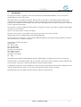
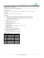
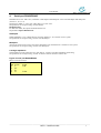
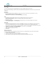
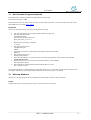
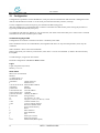
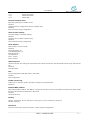
User Manual
NC9100
NC9200
NC9300
Ver 0.4
31 90 01
2004-09-14
User manual
Contents
1.
Introduction___________________________________________________________________ 3
2.
Reset button ___________________________________________________________________ 4
3.
Serial port RS232 ______________________________________________________________ 4
4.
Serial port RS422/RS485 ________________________________________________________ 7
5.
Log __________________________________________________________________________ 8
6.
Ethernet TCP/IP _______________________________________________________________ 9
7.
Gateway ______________________________________________________________________ 9
8.
Web Server ___________________________________________________________________ 9
9.
Installation ___________________________________________________________________ 10
10.
Test _______________________________________________________________________ 12
11.
Net Controller Program download______________________________________________ 13
12.
NCsetup Windows ___________________________________________________________ 13
13.
Configuration _______________________________________________________________ 14
14.
Default value________________________________________________________________ 21
15.
Reset button (R) _____________________________________________________________ 23
16.
LED function (P) (H) (A) (T) (R) _______________________________________________ 23
17.
Power (PW) Terminal-T4 connector (NC9100, NC9200) ____________________________ 23
18.
Power (PW) Jack connector ___________________________________________________ 23
19.
Network port (TP) RJ45 connector _____________________________________________ 23
20.
Serial (S1) DB9F connector (S2) (NC9200) _______________________________________ 24
21.
Digital (I/O) Terminal-T6 connector (NC9200)____________________________________ 24
22.
Connectors NC9100, NC9200 __________________________________________________ 25
23.
Connectors NC9300 __________________________________________________________ 25
24.
Cable RS232 NC-PC _________________________________________________________ 26
25.
Technical data ______________________________________________________________ 27
Restricted Rights Legend
Copyright © 1997-2004 WHI Konsult AB. All rights reserved. No part of this publication may be reproduced,
transmitted or translated in any form or by any means, electronic, mechanical, manual, optical or otherwise, without
prior written permission of WHI Konsult AB.
_______________________________________________________________________________________________
2
NET • CONTROLLER
User Manual
1.
Introduction
By using Net Controller, equipment’s with serial communication by RS232/RS422/RS485, can be connected to a
standard Ethernet network with TCP/IP.
The communication is completely transparent. Ethernet with TCP/IP offers a well thought and open architectur for
communication on different platforms regarding computers and operating systems. Gives advantage in form of easy
integration. By using the network instead of own serial cables and telephone line for modem, it is possible to reduce the
costs for installation and maintain
Net Controller is a general standalone product and easy to integrate in systems. Two models is available, table and DIN
rail model. Is power supplied
With 12-48V AC/DC. Direct or with an AC adapter.
Each Net Controller has its own IP address and each serial port has its own TCP-port number.
Handle subnets with one standard Gateway and Netmask addressing.
Net Controller has two serial ports, it can be used for different equipment, with separate remote IP-address connection.
The communication is completely transparent.
The serial port has following signals.
GND Ground
RD Receive Data
TD Transmit Data
DSR Data Set Ready
DTR Data Terminal Ready
RTS Request To Send
CTS Clear To Send
DCD Data Carrier Detect
RI Ring
Switchable between RS232 and RS422/RS485 interface. RS422/RS485 can handle 4-wire and 2-wire connections.
In modem mode, it can simulate Modem with AT commands. This function makes it possible to replace a Modem with
a Net Controller, and connect is made with IP address instead of telephone number.
Configuration of parameters such as IP-addresses, TCP-ports, Serial communication and Timeouts is managed over the
network with Web browser/Telnet or via the serial port with Terminal utility software, NCsetup.
Has Flash memory for easy update of the Net Controller software via the serial port.
________________________________________________________________________________________________
NET • CONTROLLER
3
User manual
2.
Reset button
The Reset button R with two functions, a short press make a reset, and a long press, at least in 5 sec, start the
configuration.
3.
Serial port RS232
The serial port can be setup with speed ,data format and control.
See parameter Baud rate, Serial Option Flags: Enable 8 Databits, Enable Parity, Enable Odd parity, Enable 2 Stopbits.
Terminate with character or timeout
Received characters is buffered until a defined termination character or a time gap is discovered and thereafter is send
via TCP/IP. The character and the time gap is selectable. Default time is 2 characters gap.
See parameter Serial Receive timeout, End character.
Flow Control
For flow control the RTS and CTS is used. Normal no flow control is used. With this option the RTS control the flow
from Net Controller and CTS control the flow to Net Controller.
See parameter Serial Option Flags: Enable flow control.
Modem mode
In modem mode, the Net Controller acts as Modem. Make it possible to connect with AT command and use IP address
instead of telephone number (simulate a Modem).
See parameter SerialOption Flags: Enable AT mode, Enable ATH command, Enable Close via DTR.
AT V0/1
Default value for V0/1 is selectable by this option.
With AT command V0 or V1, selects response code in numeric form V0 or text form V1.
See parameter Serial Protocol Flags: Enable Text code AT V0/1.
AT X0/1
Default value for X0/1 is selectable by this option.
With AT command X0 or X1, selects response code in standard X0 or extended X1.
See parameter Serial Protocol Flags: Enable Extended code AT X0/X1.
AT H
Allow disconnect by +++ and ATH command. If disabled, only disconnect can be made by control signal DTR or
timeout.
See parameter Enable ATH command, Enable Close via DTR.
_______________________________________________________________________________________________
4
NET • CONTROLLER
User Manual
Modem command and data state
In modem mode the Net Controller is in command or data state. In Command state, it is possible to send instruction ,
AT commands. In Data state, everything is accepted as data.
Command state
Net Controller is shifted to Command state on power up, disconnect, DTR off and on escape sequence +++
Data state
Net Controller is shifted to Data state on connect and ATO.
Commands
AT Command prefix. A AT command string must start with this characters except escape (+++).
DT Connect with IP address. The address must be 12 digits without any dots. All the digits in the
group must be filled out with zeros to three digits number. IP Adress192.168.0.1 will be
192168000001 and force to data state.
Response with CONNECT and set DCD On.
H0 Disconnect.
Response with OK and set DCD Off.
O
Go on-line and force to data state.
Response with CONNECT.
Vn Verbose response codes. V0= Numeric, V1= Text.
Response with OK.
Xn Extended response codes. X0= Standard, X1/X2/X3/X4= Extended.
Response with OK.
+++ Escape sequence, force to command state.
Response with OK.
DTR Off, disconnect and force to command state.
Response with NO CARRIER and set DCD Off.
DTR On, availble for command and listen for connect.
RI Ring and force to data state.
Response with RING, CONNECT and set DCD On.
Response code
Code
0
1
2
3
4
5
10
11
12
16
Text
OK
CONNECT
RING
NO CARRIER
ERROR
CONNECT 1200
CONNECT 2400
CONNECT 4800
CONNECT 9600
CONNECT 19200
X setup
0-4
0
0-4
0-4
0-4
1-4
1-4
1-4
1-4
1-4
________________________________________________________________________________________________
NET • CONTROLLER
5
User manual
Example on AT strings
Example on useable AT strings
Init string for extended numerical response codes
ATV0X2
OK
Connect with IP address 192.168.0.1
ATDT192168000001
CONNECT
Connect with IP address 192.168.0.2 and TCP port number 10002.
ATDT19216800000210002
CONNECT
Disconnect
+++ ATH0
OK
Entering Command state and keeping the Data connection
+++ AT
ATO
OK
CONNECT
Figure of Serial port RS232
Signal names defined with Net Controller as DCE, Data Communication Equipment.
DB9F connector RS232
Stift
Benämning
1.
>DCD
2.
>RD
3.
<TD
4.
<DTR
5.
GND
6.
>DSR
7.
<RTS
8.
>CTS
9.
>RI
_______________________________________________________________________________________________
6
NET • CONTROLLER
User Manual
4.
Serial port RS422/RS485
Selectable for 4-wire and 2-wire, with half- or full-duplex and multipoint. 2-wire use half-duplex and multipoint
(select b=1, m=1, f=1).
Signal levels: Mark “1” T/R- T/R+ (idle), Space “0” T/R+ T/R-.
See parameter Serial Option Flags: Enable RS485.
RS485 Interface
For DIN rail model, the option for RS485 must be set.
Se parameter Option RS485 Interf.
Halfduplex
When half duplex is set, it shifts between Transmit and Recive. It is used for 2-wire system.
See parameter Serial Option Flags: Enable 485-Halfduplex.
Multipoint
Activate Transmit in none-active state (free) when data’s not transmitted. It is used for 2-wire system.
See parameter Serial Option Flags: Enable 485-Multipoint.
Low/high impedance
The termination can be selected to low (120 ohm) or to high (12 k ohm) impedance terminating.
See parametrar Serial Option Flag: Enable Terminate Snd och Enable Terminate Rcv.
Figure of serial port RS422/RS485
Shows 4-wire and 2-wire.
DB9F connector RS422/RS485
Pin 4-wire
2-wire
2. TT-/R3. R+
7. R8. T+
T+/R+
________________________________________________________________________________________________
NET • CONTROLLER
7
User manual
5.
Log
To monitoring what the Net Controller is doing, the log output can be used. It is possible to select output port and log
level. The output can be serial port or Telnet.
To select the port:
1 = Serial port-1.
2 = Serial port-2.
3 = Telnet.
To select level:
0 = Nothing.
1 = Errors.
2 = Mini.
3 = All.
4 = Network.
See parameter Log Port, Log Level.
Example on output
Start
Shows version and IP settings.
>0002 NC200 STD 0.72
>0003 Ethernet
00-02-b8-00-11-89
>0004 Local IP
0.0.0.0
>0005 Netmask
255.255.255.0
>0006 Gateway
255.255.255.255
>0007 Serial-1
9600
>0008 port-1 Listen 10001
>0009 Serial-2
9600
>0010 port-2 Listen 10002
>0011 DHCP start
>0012 DHCP stop
192.168.0.168
0001
Connect
Shows connection.
>0039 port-1 Connect from 192.168.0.100
>0040 port-1 Connect 10001
Send/Receive
Shows send and receive of data.
>0020 port-1 Recv 1
>0021 port-1 Send 1
>0022 port-1 Recv 1
>0023 port-1 Send 1
Close
Shows close.
>0045 port-1 Close 10001
AT command connect
Shows connect with adtd. Response code 1=Connect.
>0044 AT-Command atdt192168000001
>0044 AT-Response 1
AT command disconnect
Shows disconnect. Response code 3=No Carrier.
>0044 AT-Response 3
_______________________________________________________________________________________________
8
NET • CONTROLLER
User Manual
6.
Ethernet TCP/IP
Communication protocol for the network is TCP/IP.
Has support for the following protocols:
• ARP Address Resolution Protocol.
• IP
Internet Protocol.
• ICMP Internet Control Message Protocol.
• UDP User Datagram Protocol.
• TCP Transmission Control Protocol.
• DHCP Dynamic Host Configuration Protocol.
• HTTP Hyper Text Transfer Protocol.
7.
Gateway
Net Controller has one default Gateway.
8.
Web Server
Net Controller has an web server for homepages used for configuration.
________________________________________________________________________________________________
NET • CONTROLLER
9
User manual
9.
Installation
Check with the network administrator if manual or automatic IP setting shall be used. (Automatic IP setting is set as
default in Net Controller, IP address is 0.0.0.0). If manual IT setting, ask for the IP settings from the network
administrator, such as IP address, netmask and deafult gateway.
On connection, check the LED P Power green is on (power and started). LED A Active/Link yellow is on (valid link
for the network).
LED H High speed green is on if 100 Mbps link.
On automatic IP setting the network have a DHCP server to assign the Net Controller (the MAC address is factory
labelled on Net Controller).
Manuel IP settings is managed over the network with Web browser/Telnet or via the serial port with Terminal utility
software, NCsetup.
Terminal
Connect an Terminal (PC) to serial port S1 and start the NCsetup (or a terminal program).
1.
2.
3.
4.
5.
6.
7.
8.
9.
Start the configuration by pressing the button R Reset (long press).
The following text shows:
Configuration mode
Net Controller NC200 STD 01.00
Enter password (j ********)
>
Enter the password with j command.
>j control
The following text shows:
Configuration open
MAIN>
Enter the IP address with a command.
MAIN>a 192.168.0.1
Store the changes to Flash memory with s command.
MAIN>s
The following text shows:
MAIN>Warning, Store Configuration to Flash? Confirm with y
Confirm with y.
MAIN>y
The following text shows:
MAIN>Store to Flash, Exiting Configuration
Net Controller has assigned an IP setting.
_______________________________________________________________________________________________
10
NET • CONTROLLER
User Manual
Telnet/Web browser
Make sure your PC is connected to the same subnetwork. The Ethernet MAC address of the Net Controller is printed on
a label, outside of the Net Controller (serial number S/N).
1.
Enter IP and MAC address with the arp command (use command):
>ARP –S 192.168.0.1 00-02-B8-00-00-01
2. Start the web browser with the assigned IP address.
http://192.168.0.1
The start page is showed.
3. Enter the password control in Enter password field and click on Ok.
The IP Settings is showed.
4. Select IP settings on the menu.
Enter the IP address in Local IP field and click on Ok.
5. Select Store to Flash memory on the menu.
Enter yes in Confirm yes/no field and click on Ok.
Net Controller has assigned an IP setting.
________________________________________________________________________________________________
NET • CONTROLLER
11
User manual
10. Test
To verify the Net Controller is configurated for the network, standard software can be used.
Ping to verify the IP settings, Telnet to verify TCP communication and Terminal to verify the serial port and modem
connection.
IP address
1. Run ping command with the IP address to verify. Net Controller is answering if the IP address is correct.
>ping 192.168.0.1 (example of assigned IP address)
Verify network communication: LED A Active/Link yellow blinking.
TCP
1. Run Telnet with the IP address and the TCP port number that the serial port is assigned to.
>telnet 192.168.0.10 10001 (example of assigned IP address and TCP port number).
Verify that it connects.
2. Send/receive data by pressing a character key. Do loopback test by connecting TD-RD on the serial port.
>112233445566778899
(Local Echo on).
Serial port
1. Run Terminal program and choise a com port with Modem. You have to use a Modem port, it is not possible to
enter the AT command characters one by one. If no Modem is installed, choise a standard Modem 9600.
Enter the Net Controllers IP address as telephone number. You have to use fix length on the number, fill out with
leading zeros on each group so the number 12 digits. 192.168.0.1 etc 192168000001
2. Connect with IP address as Telephon number.
After connection all characters is send.
3. Disconnect.
Network-Serial port
Verify the communication via the network and the serial port, by running both the Telnet and Terminal together.
1. Run the Telnet via the network.
2. Run the Terminalprogrammet via the serial port.
3. Connect the Telnet to Net Controller’s IP address and TCP port (10001).
4. Enter character from the Telnet and they will be showed on the Terminalen and reversed.
_______________________________________________________________________________________________
12
NET • CONTROLLER
User Manual
11. Net Controller Program download
Download of new software (Firmware) to upgrade the Net Controller.
The software file type is *.ihx.
The download can only be done via the serial port with NCsetup. The latest version for the Net Controller can be
dowloaded from our website www.whi.se
Download
Connect an Terminal (PC) to serial port S1 and start the NCsetup.
1.
2.
3.
4.
5.
6.
7.
8.
9.
Start the configuration by pressing the button R Reset (long press).
The following text shows:
Configuration mode
Net Controller NC200 STD 01.00
Enter password (j ********)
>
Enter the password with j command.
>j control
The following text shows:
Configuration open
MAIN>
Set the Net Controller in waiting state for download with the d command.
MAIN>d
The following text shows:
Waiting for download
Select File, Download… in NCsetup menu. Choose the download file in file window and click Ok.
NC200 STD 00.72.ihx
Platform and current version shows in Download window. Click on Start.
The download is started.
The download is completed then the Download window is closed.
Net Controller restarts.
If wrong download file is loaded and the Net Controller fault to start, it is possible to force the Net Controller into
waiting for download, by pressing the R Reset button at the same time power is connected.
12. NCsetup Windows
NCsetup is a terminal program used to communicate with the Net Controller via the serial port.
Install
Unpack and copy the file ncsetup.zip to a map. Consist of one file, ncsetup.exe.
________________________________________________________________________________________________
NET • CONTROLLER
13
User manual
13. Configuration
Configuration of parameters such as IP-addresses, TCP-ports, Serial communication and Timeouts is managed over the
network with Web browser/Telnet or via the serial port with Terminal utility software, NCsetup.
To start configuration via the serial port-2, press the button R Reset (long press).
After the configuration is completed the Net Controller is turned back to data mode by either storing the parameter or
by pressing the R Reset button (short press).
To configurate with Telnet or Webserver over the network, start either Telnet with telnet port or web browser. Terminal
and Telnet use the same command syntax, CMD.
Command language CMD
Configuration via Terminal or Telnet use the same command syntax CMD.
Each command consist of one command letter, and argument and value. To only show the parameter, enter only the
command.
With command ? shows a list of all commands.
Setting of the serial port is done by a sub menu 1 (it also has ti’s own list of commands ?). Back to the main menu by
the key Esc.
To make changes, a login must first be done.
Finish the configuration with Store to Flash or Exit.
Login
Login with password (control).
MAIN>j ********
Show menu
Show a list of commands.
MAIN>?
*** Main menu ***
NC200 STD 00.72
j nnnnnnnn
Check password
f
Enable service
e nn-nn-nn-nn-nn-nn Ethernet MAC address
i nnnnnnnn
Identity
p nnnnnnnn
Password
a nnn.nnn.nnn.nnn
Local IP address
m nnn.nnn.nnn.nnn
Netmask
g nnn.nnn.nnn.nnn
Gateway IP address
k nnnnnnnn
Encryption key
ln
Log level 0-7, 0 = Off
hn
Log port, 1=Port-1, 2=Port-2, 3=TCP
c nnn
Connect timeout (sec)
v nnn
Activity timeout (milisec)
z
Restore to default values
s
Store to flash memory
r
Reset
b
Show statistics
d
Start download
x
Exit
1
Select port-1 menu
2
Select port-2 menu
o u=1
Enable UDP (Main option)
_______________________________________________________________________________________________
14
NET • CONTROLLER
User Manual
o e=1
o p=1
o w=1
Enable Encryption
Enable Permission
Enable Web
Restore to default value
Restore the parameters to default values.
MAIN>z
Warning, Restore configuration to Flash? Confirm with y
MAIN>y
Store to Flash, Exiting Configuration
Store to flash memory
Store the changes to the Flash memory.
MAIN>s
Warning, Store to Flash? Confirm with y
MAIN>y
Store to Flash, Exiting Configuration
Show statistic
Show statistics for the network.
MAIN>b
Received packets: 10
Transmitted packets: 10
Droped packets: 0
Error packets: 0
Port-1: Closed
Port-2: Closed
Start download
Set Net Controller into waiting for download of new software (Firmware). Start download from NCsetup with selected
file.
MAIN>d
Start Download
Exit
Finish configuration mode and return to data mode.
MAIN>x
Exit Configuration
Enable service flag
Enable service functions, make it possible to change protected parameters.
MAIN>f 1
Ethernet MAC address
Show Ethernet MAC address. The address is unique for each Net Controller. The address is printed on the label outside
the Net Controller (Serial number S/N). Hex 00-ff.
MAIN>e
00-02-b8-00-02-01
Identity
Identity. 8 characters, fill out with space. Used to give every Net Controller a unique id.
MAIN>i NC9100_ _
Password
Password. 8 characters, fill out with space. Used to login for configuration.
________________________________________________________________________________________________
NET • CONTROLLER
15
User manual
MAIN>p control_
Local IP address
Net Controller’s own IP address. Point notation.
MAIN>a 192.168.0.10
Netmask
Net Controller’s own netmask. Point notation.
MAIN>m 255.255.255.0
Gateway IP address
Net Controller’s default gateway IP address. Point notation.
MAIN>g 255.255.255.255
Encryption key
Encryption key. 8 digits 64-bits key.
MAIN>k 12345678
Log port
Output port for log. 0=Turned off, 1=Serial port-1, 2=Serial port-2, 3=Telnet.
MAIN>h 1
Log level
Level for log. Selects level for the printouts. 0=Nothing. 1=Errors, 2=Connections, 3=All, 4=Network.
MAIN>l 3
Connect timeout
Sets the time for disconnect on idle line in seconds. If the communication is hold longer then the selected time, the line
is disconnected. 0-255 Seconds, 0=Disabled.
MAIN>c 100
Activity timeout
Sets the time for restart on idle activity in minutes. If the communication is hold longer than the selected time, the Net
Controller is reset. 0-255 Minutes, 0=disabled.
Main Option Enable UDP
Enable UDP instead of TCP Protocol. 0=TCP, 1=UDP.
MAIN>o u=1
Main Option Enable Encryption
Enable Encryption. 64-Bits encryption of the data.
MAIN>o e=1
Main Option Enable Permission
Enable permission control for extern connection via IP. Control against Remote IP Adress.
MAIN>o p=1
Main Option Enable Web
Enable start of Web Server.
MAIN>o w=1
_______________________________________________________________________________________________
16
NET • CONTROLLER
User Manual
Select port-1 menu
Select port-1 menu.
MAIN>1
PORT-1>
Select port-2 menu
Select port-2 menu.
MAIN>2
PORT-2>
Submenu for port-1 and port-2
Show menu
Show a list of commands for port-1 and port-2.
PORT-1>?
*** Port-1 menu ***
p nnnnn
Local TCP port
a nnn.nnn.nnn.nnn
Remote IP address
r nnnnn
Remote TCP port
b nnnnn
Baud rate
s nn
Start character
e nn
End character
t nnn
Serial recieve timeout (ms)
d nnn
RS485 timeout (ms)
o p=1
Enable Parity (Serial option)
o o=1
Enable Odd parity
o d=1
Enable 8 Databits
o s=1
Enable 2 Stopbits
o c=1
Enable Flow Control
o a=1
Enable AT commands
o h=1
Enable ATH commands
o t=1
Enable Close via DTR
o r=1
Enable Remote connect
o l=1
Enable Local connect
o k=1
Enable Break signal
o b=1
Enable RS485
o m=1
Enable Multipoint
o f=1
Enable Half duplex
o x=1
Enable Termination Rcv 120 ohm
o z=1
Enable Termination Snd 120 ohm
c v=1
Enable Text code AT V1
c x=1
Enable Extended code AT X1
c a=1
Enable Code AT CONNECT 1200
c c=1
Enable Control header
c h=1
Enable Handshaking
c e=1
Enable Exomatic
c n=1
Enable Nova tune
Back
Return to main menu from port-1 or port-2 menu.
PORT-1>Esc
MAIN>
Baud rate
Set communication speed for serial port. Speed 300-115200 bps.
PORT-1>b 9600
________________________________________________________________________________________________
NET • CONTROLLER
17
User manual
Serial recieve timeout
Sets the time for received time gap for serial port. Time = value x 4 x Bit-period. 0-255, 0=disabled.
PORT-1>t 10
RS485 timeout
Sets the time for activate Receive after Send for serial port RS485 in milliseconds. 1-255mS, 0=disabled.
PORT-1>t 5
Local TCP port
Net Controllers own TCP port number for serial port. Use number higher then 5000.
PORT-1>p 10001
Remote IP address
IP Address for the remote connection for serial port. Is the host the Net Controller is connected to on data received on
serial port. Point notation.
PORT-1>a 192.168.0.200
Remote TCP port
TCP port number for the remote connection for serial port. Is the host the Net Controller is connected to on data
received on serial port. Use number higher then 5000.
PORT-1>p 10001
Start character
Not used.
PORT-1>s 02 (Stx)
End character
Set the terminating character for received messages. The received character is buffered until a termination character or a
time gap obtained.
PORT-1>e 03 (Etx)
Serial Option Enable Parity
Enable the parity for the serial port.
Aktiverar paritetskontroll för serieport.
PORT-1>o p=1
Serial Option Enable Odd parity
Select the parity for the serial port between odd, even. 0=Even, 1=odd parity.
PORT-1>o o=1
Serial Option Enable 8 Databits
Select the number of data bits for the serial port between 7 or 8. 0=7 Data bits, 0=8 Data bits.
PORT-1>o d=1
Serial Option Enable 2 Stopbits
Select the number of stop bits for the serial port between 1 or 2. 0=1 Stop bit, 1=stop bits.
PORT-1>o s=1
Serial Option Enable Flow control
Enable the flow control for serial port. On flow control the control signal RTS is used for data from Net Controller, and
CTS is used for data to Net Controller.
PORT-1>o c=1
_______________________________________________________________________________________________
18
NET • CONTROLLER
User Manual
Serial Option Enable AT mode
Enable Modem mode and use AT commands. All command strings must start with the prefix AT. DTR must be On.
The line goes disconnected by ATH command or set the DTR Off.
PORT-1>o a=1
Serial Option Enable ATH command
Enable detect of ATH command. In this option, the Net Controller is disconnect by timeout or control signal DTR.
PORT-1>o h=1
Serial Option Enable Close via DTR
Enable close with control signal DTR. By set DTR Off, the Net Controller disconnect.
PORT-1>o t=1
Serial Option Enable Remote connect
Enable to allow remote connections from remote host. If disabled the connection can only be made locally by received
characters on serial port.
Aktiverar anslutning externt för serieport. 1=Tillåter anslutning till TCP-port, 0=Ingen anslutning tillåten.
PORT-1>o r=1
Serial Option Enable Local connect
Enable to allow local connection on received characters on serial port. If disabled the connection can only be made by
remote host.
Aktiverar lokal anslutning för serieport. 1=Tillåter anslutning via serieport, 0=Ingen anslutning tillåten.
PORT-1>o l=1
Serial Option Enable Break signal
Enable to send/receive BREAK signal over the network for serial port.
PORT-1>o k=1
Serial Option Enable RS485
Enable RS422/RS485 interface for serial port. 0=RS232, 1=RS422/RS485.
PORT-1>o b=1
Serial Option Enable 485-Multipoint
Enable Z-state. The transmit line is in high impedance if nothing has to sent. Used in multipoint environment.
PORT-1>o m=1
Serial Option Enable 485-Halfduplex
Enable halfduplex. The receiver is turned off if a transmit is going on. Used in half duplex environment. In full duplex
mode the receiver is always turned on. 0=Full, 1=Half duplex
PORT-1>o f=1
Serial Option Enable Termination Rcv
Enable low impedance termination (120ohm) for receive (RS485). 0=High termination, 1= Low termination.
PORT-1>o x=1
Serial Option Enable Termination Snd
Enable low impedance termination (120ohm) for transmit (RS485). 0=High termination, 1= Low termination.
PORT-1>o z=1
________________________________________________________________________________________________
NET • CONTROLLER
19
User manual
Protocol Enable Text code AT V0/1
Sets the default value for AT command Verbose response codes. 0= V0 numeric codes, 1=V1 text codes.
PORT-1>c v=1
Protocol Enable Extended code AT X0/1
Sets the default value for AT command Extension response codes. 0=X0 basics, 1=X1/X2/X3/X4 extended codes.
PORT-1>c x=1
Protocol Enable Code AT CONNECT 1200
Sets the default value for response code. 0=Standard, 1=CONNECT 1200 response code..
PORT-1>c a=1
Protocol Enable Control header
Enable protocol header.
PORT-1>c c=1
Protocol Enable Handshaking
Enable handshaking using signals RTS and CTS.
PORT-1>c h=1
Protocol Enable Exomatic
Enable Exomatic filter for serial port.
PORT-1>c e=1
Protocol Enable Nova tune
Enable Nova tune protocol for serial port.
PORT-1>c n=1
_______________________________________________________________________________________________
20
NET • CONTROLLER
User Manual
14. Default value
After clear the parameter has following values.
Main
Fält
e
i
p
a
m
g
k
L
h
C
v
ou
oe
op
ow
Värde
00-02-B8-00-00-01
NC910001
Control
0.0.0.0
255.255.255.0
255.255.255.255
12345678
3
0
10
0
0
0
0
1
Beskrivning
Ethernet MAC address
Identity (typ + mac)
Password
Local IP address
Netmask
Gateway IP address
Encryption key
Log level
Log port
Connection timeout (sec)
Activity timeout (min)
Option Enable UDP
Option Enable Encryption
Option Enable Permission
Option Enable Web
________________________________________________________________________________________________
NET • CONTROLLER
21
User manual
Port-1/-2
Fält
Värde
p
10001/10002
a
0.0.0.0
r
10001/10002
b
9600
t
10
d
10
S
00
E
00
op
0
oo
0
od
1
os
0
oc
0
oa
0
oh
0
ot
0
or
1
ol
1
ok
0
ob
0
om
0
of
0
ox
0
oz
0
cv
0
cx
0
ca
0
cc
0
ch
0
ce
0
cn
0
Beskrivning
Local TCP port
Remote IP address
Remote TCP port
Baud rate
Receive timeout (bits)
RS485 timeout (ms)
Start character
End character
Serial Option Enable Parity
Serial Option Enable Odd
Serial Option Enable 8 Databits
Serial Option Enable 2 Stopbits
Serial Option Enable Flow Control
Serial Option Enable AT Command
Serial Option Enable ATH Command
Serial Option Enable Close via DTR
Serial Option Enable Remote connect
Serial Option Enable Local connect
Serial Option Enable Break signal
Serial Option Enable RS485
Serial Option Enable RS485 Multi point
Serial Option Enable RS485 Half Duplex
Serial Option Enable Termination Rcv
Serial Option Enable Termination Snd
Serial Protocol Enable Text code AT V1
Serial Protocol Enable Extended code AT X1
Serial Protocol Enable Code AT CONNECT 1200
Serial Protocol Enable Control header
Serial Protocol Enable Handshaking
Serial Protocol Enable Exomatic
Serial Protocol Enable Nova Tune
_______________________________________________________________________________________________
22
NET • CONTROLLER
User Manual
15. Reset button (R)
Pos
Name
Type
Description
R
RESET
Short press
Restart
R
CONFIG
Long press (3 sec)
Start configuration
16. LED function (P) (H) (A) (T) (R)
LED
Benämning
Colour
Description
P
Name
Green
Power and started
H
High Speed
Green
High speed 100 Mbps
A
LINK/ACTIVITY
Yellow
Link ok
A
LINK/ACTIVITY
Yellow blinking
Activity network
T
TRANSMIT DATA 1
Yellow blinking
Serial port-1 Transmit
R
RECEIVE DATA 1
Yellow blinking
Serial port-1 Receive
T
TRANSMIT DATA 2
Yellow blinking
Serial port-2 Transmit
R
RECEIVE DATA 2
Yellow blinking
Serial port-2 Receive
17. Power (PW) Terminal-T4 connector (NC9100, NC9200)
Pin
Text
Name
Decsription
1
+
12-48V AC/DC+ Primary
Power+ Primary
2
+
12-48V AC/DC+ Secondary
Power+ Secondary
3
0
12-48V AC/DC-
Power-
4
z
PGND
Protective ground
18. Power (PW) Jack connector
Pin
Name
Description
Pin
12-48V AC/DC-
Power
Header 12-48V AC/DC+
Power
19. Network port (TP) RJ45 connector
TP
10Base-T/100Base-TX
________________________________________________________________________________________________
NET • CONTROLLER
23
User manual
20. Serial (S1) DB9F connector (S2) (NC9200)
Pin
Name
Type
1
DCD
Output
2
RD/T-(R-)
Output
3
TD/R+
Input
4
DTR
Input
5
GND
Ground
6
DSR
Output
7
RTS/R-
Input
8
CTS/T+(R+) Output
9
RI
Output
21. Digital (I/O) Terminal-T6 connector (NC9200)
Pos
Name
Type
Description
1 (*) IN0
Input
Digital in-0
2
IN1A
Input
Digital in-1 anode
3
IN1C
Input
Digital in-1 catode
4
OUT0
Output
Digital out-0
5
OUT1
Output
Digital out-1
6
GND
Ground
(*) Position 1 top of terminal
Signal ground
_______________________________________________________________________________________________
24
NET • CONTROLLER
User Manual
22. Connectors NC9100, NC9200
Figure on connections for serial ports,
I/O port and TP port
Figure on connections for Power
R
I/O
1
P
H A
Tp
T R
T
S2
R
S1
23. Connectors NC9300
Figure on connections for serial port and power
P
PW
S1
TR
Figure on connections for TP port
A
TP
H
R
________________________________________________________________________________________________
NET • CONTROLLER
25
User manual
24. Cable RS232 NC-PC
31 60 01 RS232 cable NC-PC
Serial cable for RS232 to PC, DB9M (Male) - DB9F (Female)
DB9M
1.
2.
3.
4.
5.
6.
7.
8.
9.
DB9F
>DCD
>RD
<TD
<DTR
GND
>DSR
<RTS
>CTS
>RI
black
brown
red
orange
yellow
green
blue
violette
grey
1.
2.
3.
4.
5.
6.
7.
8.
9.
_______________________________________________________________________________________________
26
NET • CONTROLLER
User Manual
25. Technical data
Processor 32-bits Risc 33 MHz.
Data memory 256 Kbytes SRAM for stack and buffers
Flash for easy update of software
Ethernet IEEE 802.3 10/100Mbps 10Base-T/100Base-TX RJ45.
Serial port RS232/RS422/RS485, complet control signaler DB9F.
Low power arkitecture with 3.3V logic.
Watchdog for program execution and restart on fault
Integrated power supply for external AC adapter
Power indicator green LED o indicate power and started.
High speed indicator with green LED to indicate 100 Mbps network communications
Link/Activity indicator with yellow LED to indicate link and network communications
Serial indicator R1 and T1 with yellow LED to indicate serial communication
TCP/IP-protocol with support for protocols ARP, IP, ICMP, TCP, UDP, DHCP and HTTP
Power requirements 12-48V AC/DC, 80mA
Physical dimensions
NC9100 100 x 95 x 21 mm.
NC9200 100 x 95 x 38 mm.
NC9300 88 x 71 x 18 mm.
Weights
NC9100 150 g.
NC9200 240g.
NC9300 86 g.
Ambient temperature 5-50°C/normal, -40-80°C/stock
Relative humidity 5-95% none-condensing
Assembled with case feet, case hole or DIN-rail
CE, confirms the requirements for Electromagnetic Compatibility according to EMC-directive
________________________________________________________________________________________________
NET • CONTROLLER
27