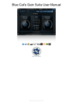
1
Knobby/Slidemate
MIDI Controller
User’s Manual
Thank you for purchasing an Encore Electronics product. This manual
depicts images of the Knobby®, but it applies exactly the same to the
Slidemate®. The two products are functionally and electrically
equivalent with the exception of the control style (knobs versus sliders)
This manual will cover installing and launching the software, learning
about various file types, and the stuff you want to know to get up and
running fast. It is not a repeat of the online help. Please read that when
you get a chance. What we thought would be appropriate for a user’s
manual is to end it with several examples for setting up various
instrument profiles.
You should have received these items in the Knobby package:
1 – Knobby
1 – Power supply (9volts AC)
1 – Floppy disk
1 – User’s Manual
Depending on your specific equipment, there are many, many ways to
connect the Knobby to your system. If
you plan on using the Knobby with
software synthesizers only, this would be
a typical connection. (Figure 1)
Using a pair of MIDI cables, connect the
Knobby to your computer’s MIDI ports.
Also connect the power supply to the
Knobby and plug it in the wall. The
power supply is not shown in the
following diagrams.
Figure 1
Encore Electronics ©2001
www.encoreelectronics.com
Figure 2 shows a typical connection if you have one keyboard and a
computer. In this configuration, you might want to disable local control
on the keyboard, or turn off MIDI echo in the computer. This will
prevent you from doubling using extra voices on your keyboard, unless
that is what you want! The Knobby is small enough to sit comfortably on
many keyboards, yet heavy enough it won’t slide off when you’re
tweaking!! In this configuration, the keyboard must be able to echo data
in order for the Knobby to receive commands from the computer. This is
only necessary when you are programming the Knobby. If the Knobby is
already configured, then this setup will work fine.
Figure 2
Figure 3 shows a more complex setup that includes a master controller,
computer, sound module, and your Knobby. The Knobby is in the
location shown so that the computer can record any edits that are
performed on the Knobby. As in the previous example, to program the
Knobby it must be logically connected to the computer. The can be
accomplished with a direct connection as shown in Figure 1, or through a
MIDI patch bay or other hardware.
Figure 3
Next, you need to load the included application onto your computer.
Install it to wherever you choose, but the default “C:\Program
Files\KnobbyEd” is a good place. The installer will ask if you want to
launch the program; go ahead and launch it! The first time you launch
KnobbyEd, it will ask you for a default MIDI interface. You must select
an input and an output in order for KnobbyEd to communicate with the
Knobby hardware. It will also ask if you have a Knobby or a Slidemate.
This is asked only so the application will display the proper bitmap of the
controller you purchased. If you selected “Knobby,” you should then see
the application as shown in Figure 4.
Figure 4
The Knobby ships with definitions for several instruments, and more are
being added regularly to the website. Before trying to build a profile of
your own, we encourage you to check the website as necessary:
www.encoreelectronics.com.
If you can’t wait for us to support a particular instrument, and you
already know where to put the floppy disk, jump to the section entitled
“Instruments.”
Group Buttons
KnobbyEd will default to all the knobs un-assigned. [Note: The
Slidemate and Knobby now ship preprogrammed with 120 standard
MIDI controllers set to channel 1]
The group buttons are used to change between sets of knob definitions.
You can press one or multiple buttons at a time, for a total of fifteen
groups. The LEDs will indicate the current group.
To check your connection to the Knobby, press any of the GROUP
buttons, and you should see the on-screen image reflect the status of the
Knobby itself. If you don’t, go to the section on troubleshooting.
Use these group buttons to organize your instrument programming. For
instance, you could set GroupA to be 8 parameters for VCO1, GroupB to
be 8 parameters for VCO2, GroupAB to be 8 parameters for the VCF,
etc. You can think of the group buttons as giving you 15 programs per
controller.
You can browse the instrument panel on the left of the application for
your particular equipment. When you find something you would like to
control, simply click on the “+” next to the instrument’s name and you
will see a list of all the editable parameters. Drag and drop from this list
onto a knob and it programmed! You can also drop onto the text area
below the knobs if you prefer.
If you are curious about the details of a command and what it’s actually
doing, double-click on a knob or text area. You will see the knob
properties box that has the name of the knob, the type of message, and all
the data necessary in creating the message. The online help has detailed
information regarding this area.
What we are going to concentrate on next are specific areas of Knobby
and KnobbyEd. With all the reference data in the world, sometimes it’s
easier to have a friend explain something to you. We’re going to attempt
that here.
MIDI LED
The MIDI LED indicates MIDI activity. The Knobby has a MIDI merger
built in, and this LED will show incoming activity as well as MIDI data
generated by the Knobby/Slidemate. The brightness will change
depending on the amount of data being generated. The MIDI LED will
not light if you move a knob that is unassigned.
Knob Behavior
In MIDI controllers, there are various methods to implement the way
data is sent when the knob is moved. The 8 knobs on Knobby have a
memory for every group. If you are moving knobs in one group and
switch to another group, Knobby remembers where the knobs were
located in the first group. When you return to that first group, the knobs
probably won’t be in the exact location. As you move a knob, you have
to cross the old location before it starts transmitting data. This prevents a
jump in the parameter you’re controlling. If you are selecting a group for
the first time, Knobby will begin transmitting immediately upon knob
movement. If a knob is unassigned, it will not transmit when you move it
and the MIDI LED will not light.
Scene / Panic
The button near the upper right corner of the front panel is labeled
“Scene.” When the Scene button is pressed, the Slidemate/Knobby will
transmit the current values of all eight knobs in the current group. A
sequencer can capture this so the parameters can be restored in a future
performance.
There is a “hidden” feature of the Scene button. If you hold it for about a
second, it also performs a panic function. What is that, you might ask?
Have you ever been playing your keyboards and at some point you heard
a bunch of notes you didn’t play, or you released a bunch of notes, but
some would hang and never stop? The panic function tries to turn off
those stuck notes for you. It sends a lot of MIDI data, trying to use some
of the smarter MIDI commands like all notes off, and reset controllers,
but if those don’t work then it tries to turn off every note on every
channel very quickly.
Hardware Initialization
There are situations that can scramble the memory in a Knobby. For
instance, if you are downloading data to the Knobby and the power was
suddenly removed, the Knobby could trash its memory. (Just like a
computer) Fortunately, we provided a way to “reinitialize” the data.
1.Unplug the Knobby
2. Press buttons: GROUPA, GROUPB, GROUPD
3. While you are pressing the three buttons, plug in the Knobby.
4. You should see the MIDI LED flashing.
5. Once it's flashing, unplug the Knobby.
Now try and use it as you did before. The ID should be 0. You should
program the knobs with "new" data. If that doesn’t fix your problem,
email [email protected]
Library
The library is the list you see on the left side of the application. There are
full editing capabilities on this library, so be aware you can delete library
objects as easily as you can create them. If you double click on an
instrument (or single click on the + symbol next to an instrument), you
will see all the definitions available. To the left of each name is a graphic
letter, denoting whether it’s a controller (C), NRPN (N), RPN (R), or
sysex (S) message.
KnobbyEd can read two types of files, a KNL binary file, and an INI text
file. The INI file is what you would use to create several knob definitions
for an instrument at one time. You can create this type of file in any text
editor and once you are done, KnobbyEd will read it and convert the data
you created into an instrument definition within the application. You can
also import and export a binary file that has the KNL extension. The
KNL file is the only way to save an instrument with KnobbyEd.
It is useful to exchange or save all your instrument definitions in one file.
You can also save an individual definition by selecting that particular
instrument before performing the “Library-Export Instrument” function.
When you start creating your own library, you should save your work at
regular intervals. If you accidentally press the delete key while a library
definition is selected, KnobbyEd will ask you if you are sure you want to
delete it. If you still manage to delete an instrument and it’s one Encore
has provided, you can reload it from the disk if you want it back. If you
installed the application to the default area, these files are in the
subdirectory:
C:\Program Files\KnobbyEd\Instruments
We recommend using the text file approach when creating instrument
definitions. If you use the application and you make a mistake in the
sysex header or byte location, you have to fix the mistake manually in
every definition. If you use the INI file method, it’s a simple process to
make the fix once in the INI file, and re-import it into KnobbyEd.
Instruments
Example 1
To create a new instrument definition, click on Library-New
Instrument. In the library window, you will be prompted to change the
name of the newly added instrument. To added new definitions for this
new instrument, click on Library-New Definition and a window called
“Knob Properties” will appear. If you cannot select New Definition, it is
because you have inadvertently clicked somewhere else on your screen
and no longer have an instrument selected. KnobbyEd needs to know
what instrument you want to add definitions and that’s why an
instrument in the left panel needs to be selected
This example will describe the “Lower Partial TVF Cutoff Frequency”
for a Roland D50. The D50 is programmed using sysex commands, and
this example is good because it shows the use of the checksum feature.
Here is the sysex command:
Try creating one definition and test it before you define more. The sysex
documentation is sometimes confusing, even for us! Once you get the
hang of creating sysex definitions, you will probably want to use the INI
file method from this point forward. We have included several examples
later in this document and we encourage you to look at the ones we
provide.
F0 41 00 14 12 00 01 4D xx cs F7
where xx is the changing data value, and “cs” is the checksum. The
underline shows the start of the checksum calculation, and on any
particular instrument, it will always be the same. If you are creating an
.INI file, once you get the checksum right for one of them, it’s right for
all of them.
The entries you need within KnobbyEd are:
Configurations
Once you setup the Knobby to do exactly what you want, you can save
the configuration by using the File-Save or Save As command. You will
be prompted for a file name. There are no restrictions on the name length
other than what is imposed by the operating system. These files have a
“.KNB” extension and you can share these with other people if you want
them to have the same cool setup as you.
Programming Examples
The following pages are the real hands-on tutorial of the manual. These
examples should help clarify some of the programming issues when
creating instrument profiles. Each example will describe the basic
message that the instrument responds to, followed by the parameters in
the knob properties window (if you were editing just one parameter), and
finally an INI text file example for the same definition. Once you see the
INI file example, and correlate the sysex documentation you may have in
your studio, you can just keep added definitions to the INI file. When
you complete an INI file, import it to KnobbyEd and you’re done!
The Message format area is where you enter the bulk of the message. In
this area, you must put a place marker for the data byte(s). Use 00 for the
marker. You do not have to add a place marker for the checksum, it will
be added automatically. Also notice you do not have to add the initial F0,
or final F7 bytes. The software automatically adds these for you because
every sysex message begins and ends with these two bytes. The Data
bytes field indicates 1 data byte and it is represented by the xx in the
sample message. The MSB location tells the software where you want the
changing data to be placed within the message. Here, it is shown as byte
7. When trying to figure out the location, you never include the F0 in
your count, and you start counting with numeral 0. So in the Message
format area, the 41 would be zero, 00 would be one, 14 would be two, 12
would be three, etc.
To enable checksum calculations, the Checksum box must be…checked!
The Checksum start location indicates where the checksum should start
computing. In this case, it’s byte 4. If this is set incorrectly, the message
will not work. You must understand the sysex documents that came with
your particular equipment. It’s always a good idea to get one message
working before you continue on to other messages.
Now let’s visit the text file for the same instrument. This method is
better for setting up several parameters at one time.
The other method of creating definitions is the INI file as mentioned
previously. You can create several definitions at the same time using this
method. The top of the INI file defines how the messages are assembled
and it’s followed by a list of parameters and their ranges.
An INI file for the D50 would look like this:
[Roland D50 Lower Partial 1:Sysex]
MessageFormat = 41 00 14 12 00 01 00 00
DataBytes = 1
DataNybblize =1
ParameterBytes = 1
ParameterLocation = 6
MsbLocation = 7
DeviceIdLocation = 1
DeviceIdMask = 15
DeviceId = 0
ChecksumLocation = 4
…
77 = TVF Cutoff Frequency, 0, 100
64 = WG Pitch Coarse, 0, 72
65 = WG Pitch Fine, 0, 100
…
The INI file starts with the name of the instrument, along with a
designator that indicates what type of messages are defined in the
section. The designator must begin with one of the following strings:
:Sysex
:Controllers
:NRPN
The designator can then be followed by any text, separated from the first
word by a space. Note that the designator must begin with a colon (:),
and there must be no spaces to either side of the colon. This also means
that the name of the instrument itself cannot contain a colon.
The MessageFormat entry defines the bytes that make up the message. It
is subject to the same rules that govern the Message format field in the
Knob Properties dialog: all entries must be in hex, and there must be one
byte for each byte in the final message, except for the checksum and
bracketing F0/F7 bytes. Because this entry will be used for all
parameters, there is no need to enter the specific parameter byte(s); these
are taken from the individual parameter entries.
The DataBytes, MsbLocation, LsbLocation, DataNybblize, and
ChecksumLocation entries are also similar to the corresponding fields in
the KnobbyEd dialog. The LsbLocation entry is not required if the
message only uses a single data byte, as in the example above.
DataNybblize should be set to 0 for 7-bit data, or 1 for 4-bit (nybblized)
data. DataNybblize can also be considered optional if the data is 7bit
format. ChecksumLocation should be set to -1 if no checksum is
required.
The ParameterBytes and ParameterLocation entries determine how the
parameter number is inserted in the string, in much the same way that
DataBytes and MsbLocation/LsbLocation do for data. However, when
two parameter bytes are present, it is assumed that they are adjacent. The
ByteOrder entry determines the order of the parameter bytes, and should
be set to 0 if the MSB is first, or 1 if the LSB is first. ParameterNybblize
is analogous to DataNybblize, and should be set to 0 for 7-bit parameter
number packing, or 1 for 4-bit (nybblized) packing. . (If there is only one
parameter byte, the ByteOrder and ParameterNybblize are optional.)
The DeviceIdLocation and DeviceIdMask entries determine where and
how the device ID is stored, if the instrument supports a device ID. The
location is relative to the first byte of the message body, that is, the first
byte after the F0. The mask is a decimal number that specifies which of
the lower bits contains the ID; this is usually 15, 31, or 127. The
DeviceId entry sets the default device ID for the instrument.
In the above INI file, we have included 3 examples of specific messages.
The first one is 77 and is a decimal number that is equivalent to 4D hex
(as shown in the Knob Properties dialog box). The other two lines below
TVF Cutoff Frequency represent two other parameters of the D50. In the
actual INI file, this list is quite long.
There are three things to point out regarding this list:
1) All numbers are in decimal
2) The step parameter is optional. The D50 does not require a step
parameter, and as you can see, only two numbers follow the
parameter name in the list above. The numbers are the minimum
and maximum, and commas separate them. If a third number is
not present, the parameter will default to a step size of one.
3) The ordered list of the parameters doesn’t have to be specific.
Notice the 77 is before the 64? This numeric list can be in any
order, although from low to high is probably the best way.
Example 2
This example will describe a Waldorf Microwave II parameter. The
Microwave II is also programmed using sysex commands. This example
is good because it introduces a new parameter called the “Step size.”
Here is the sysex command:
F0 3E 0E 00 20 00 00 01 xx F7
where xx is the changing data value. Unlike example 1, there is no use of
a checksum in this message; therefore you will not see the “cs.”
The entries you need within KnobbyEd are:
This message doesn’t use the checksum feature; notice the Checksum
box is unchecked, and the start location is grayed out. As in example 1,
this message has only one data byte and it is defined to be at location 7.
Remember, counting in the Message format area, the 3E would be zero,
0E would be one, 00 would be two, 20 would be three, etc. This is
important to remember when trying to get the MSB location in the
correct spot.
The new parameter is the Step size, and it is used to increment the
parameter in values other than one. In this example, the step size is 12,
and the data starts at 16. The first few number that would be generated
would be 16, 28, 40, 52, etc. up to 112. When using the Step size, you
must be aware that the step needs to fit within the lower and upper limits.
Here is an example of what would NOT work.
Data Minimum=0
Data Maximum = 10
Step size = 20
What happens in this example is that the minimum is set to zero, but the
step is set beyond the maximum. The first value it wants to transmit is 20
(because of the step size) but the maximum is limited to 10, so it doesn’t
transmit anything.
Example 3
This example will describe the “Pitch Eg Start Level” for a Korg N264.
The Korg N264 is also programmed using sysex commands. This
example is different from the previous examples because it introduces
two-byte data values.
Here is the sysex command:
F0 42 30 35 41 03 00 xl xm F7
The entries you need within KnobbyEd are:
Now if you were to reverse the Data Maximum and Step size:
Data Minimum=0
Data Maximum =20
Step size = 10
Knobby would generate three values: 0,10,20.
An INI file for the Microwave II would look like this:
[Waldorf Microwave II:Sysex]
MessageFormat = 3E 0E 00 20 00 00 00 00
DataBytes = 1
ParameterBytes = 2
ByteOrder = 0
MsbLocation = 7
ParameterLocation = 5
DeviceIdLocation = 2
DeviceIdMask = 127
DeviceId = 127
1 = Osc 1 Octave, 16, 112, 12
2 = Osc 1 Semitone, 52, 76
…
Notice the first entry has three number that follow the name. The third
number is the step size. If it is missing, as is the case with the second
entry, the step size is assumed to be 1.
The Data bytes entry is now 2. When you have two data bytes, a couple
more parameters are needed to define the message. They are Data
packing and LSB location. Data packing defines how the data is
organized within the bytes marked as xl and xm. It is equivalent to
DataNybblize in the INI file. LSB location is similar to MSB location. It
defines where the LSB is positioned in the message. In this case, it is just
before the MSB, and its value is 6. Other instruments may have the data
in opposite order.
Something else new in this example is the Data minimum value; it’s
shown as a negative number! You can enter positive or negative numbers
in the Data minimum and Data maximum fields. If you swap the min and
max values, you will create an inversion in the knob data. Pretty cool!
As you can see, this message now looks very confusing. The byte “3g” is
where the Device ID is hidden (as represented by the “g”). In this
instrument, the byte is typically 30. If it is necessary to change the ID of
the message, the DeviceIdLocation and DeviceIdMask instruct
KnobbyEd how to do it.
An INI file for the Korg N264/N364 would look like this:
[Korg N264/N364 Parameter:Sysex]
MessageFormat = 42 30 35 41 00 00 00 00
DataBytes = 2
DataNybblize = 0
MsbLocation = 7
LsbLocation = 6
ChecksumLocation = -1
ParameterBytes = 2
ParameterLsbFirst = 1
ParameterLocation = 4
ParameterNybblize = 0
DeviceIdLocation = 1
DeviceIdMask = 15
DeviceId = 0
00 =
01 =
02 =
03 =
…
Oscillator Mode, 0, 2
Oscillator Assign, 0, 1
Oscillator Hold, 0, 2, 2
Pitch Eg Start Level, -99, 99
We are going to show the raw detail of this example. The initial message
show in each of these three examples is a specific message for the
respective instrument. There are even more details about the format of
the message which have been implied in our INI file. The real structure
behind all the messages in example 3 is show here:
F0 42 3g 35 41 pl pm xl xm F7
3g = Device ID
pl = Parameter # LSB
pm = Parameter # MSB
xl = Data LSB
xm = Data MSB
The “pl” and “ph” are the parameter “low” and parameter “high’
locations. Instruments often have two bytes to represent the parameter if
there are more than 128 parameters. (128 is all that will fit in one byte
here) With two bytes, an instrument can represent over 16000
parameters! The list that follows the INI header is quite long. We only
show the first four entries. The leftmost column in the list is the
parameter number. It is inserted by KnobbyEd into the “pl” and “ph”
locations.
The “xl” and “xh” are the data LSB and MSB respectively. You can see
that the MsbLocation points to the “xh” value, and the LsbLocation
points to the “xl” value. If you get these backwards, the target instrument
will act very strangely!
If something isn’t clear in this example, please read the preceding two
examples. There are terms defined in those examples and are not
repeated. (This is beneficial for those of you that read a manual from
front to back and don’t want to read the same things over and over!)
If you still have trouble understanding MIDI, SYSEX and INI files, there
are lots of resources available on the web. If you can’t find any, please
ask us!
You can get help at: [email protected]
Troubleshooting
Here we will try and answer the most common questions.
Q: KnobbyEd does not control the Knobby, what’s wrong?
A: Check the unit ID and make sure KnobbyEd is talking to the same ID
as you Knobby. The Knobby ships from the factory as ID=0, so if you
haven’t messed with it, it should work.
Q: I can’t remember what is programmed in my Knobby; how do I read
it?
A: In the file menu, use the “Upload from Knobby” command. This will
read all the programming information from your Knobby.
Q: The MIDI LED stays on bright when I move a knob; I have to unplug
the MIDI cable to stop it. What’s wrong?
A: The port that Knobby is attached to has MIDI echo enabled. When
Knobby sends a message, the port is receiving it and sending it back to
Knobby, which sends it back to the port, etc. This is call MIDI feedback.
You have to disable MIDI echo for that port according to the instruction
that came with your interface. Another possibility is another application
has enabled MIDI echo. This is common with sequencers.
Q: A friend wants a program I created. How do I transfer it into their
Knobby?
A: you cannot directly transfer from Knobby to Knobby. You must use
the application KnobbyEd. In the file menu, use the “Upload from
Knobby” command. This will read all the programming information from
your Knobby. Plug in your friend’s Knobby and use the command:
“Download to Knobby.”
Q: Why does my synthesizer lock up when using the Knobby?
A: There may be too much data for some synthesizers to handle. Try
setting the delay parameter to some value other than zero. Start with 99
to see if that fixes the problem, and then start making the value smaller
but not so small the problem reoccurs.
Q: Can I share instrument definitions between a Mac and a PC?
A. Yes, the instrument definitions (INI files) are compatible.
Q. None of these questions is MY question. Now what?
A. Go to our website and see if you question has been answered there. If
not, email us at: [email protected]. You will get a prompt
reply, we promise!