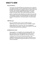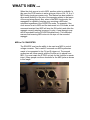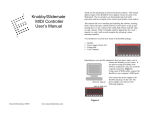
1
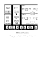
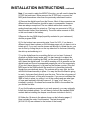
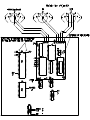
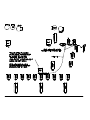
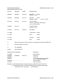
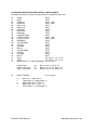
Moog Source MIDI KIT
User's Manual
Version 4.11
Encore Electronics 2455 Bates Ave. Unit E. Concord, CA 94520
email: [email protected] website:www.encoreelectronics.com
INTRODUCTION
Thank you for purchasing an Encore product.
We hope you are as excited about analog synthesis as we are!
Now that you are equipped with your SOURCE MIDI KIT memory
expansion, your SOURCE is no longer obsolete. The new additions to
your instrument: MIDI response, sixteen times more memory, MIDI to
CV converter, and an arpeggiator capable of being clocked from MIDI,
will allow you to utilize the unique sound of the SOURCE while at the
same time incorporating it into your total music system.
This user's guide has been split into four sections. It will be brief and
painless so please read it. In the first section, you will find step-bystep instructions on the new functions of the SMK. (A quick reference,
if you will) This will be followed by a summary of the newly added
features. Next, you will find a section on System Characteristics that
may answer some question as to why things are the way they are.
And finally, the installation and calibration instructions. Aside from the
modifications covered in this manual, the operation of the SOURCE
remains the same.
Quick Reference Guide
Keys and Controls
All of the new functions can be accessed by the orange buttons with
one exception: The MIDI channel select has been incorporated into the
incremental controller. This was done because there are seventeen
parameters, 1-16 for channels and 0 for Omni On. The other new
features are single or double press parameters. They are all accessed
as LEVEL 2 parameters.
SINGLE PRESS PARAMETERS
To Toggle Between Internal Clock and MIDI Clock
Press [LEVEL 2]
Press [2]
To Manually Disable The Octave Buttons For Octave Enable
Press [LEVEL 2]
Press [6]
To Select A New Bank
Press and hold [LEVEL 1]
While holding, you will see the current bank displayed in the edit LEDs
- Now select a bank by pressing one of the 16 orange program
buttons. You will see the new bank number when you release the
program button.
DOUBLE PRESS PARAMETERS
To Select A Different MIDI Clock Per Quarter Note (PPQ):
Press [LEVEL 2]
Press [5] You will see the current pulses per quarter note displayed
in the edit LEDs.
- Now press one of the first four orange buttons to select 3, 6, 12, or
24 PPQ respectively.
(NOTE: You must press an orange button after pressing [5]. The
SOURCE will not let you get out of this mode until you complete the
sequence).
Quick Reference Guide, cont
To change MIDI Channels
Press [LEVEL 2]
Press [1] The current channel (or Omni) will be displayed on the edit
LEDs.
- Now turn the incremental controller to change channels. After
selecting a channel, either press a different yellow button to edit, or
select an orange patch button. This will lock the most recently
selected channel into memory.
NOTE: Use caution when performing the channel selection
parameter. As with any other incremental controller parameter, the
SOURCE will edit the current parameter until a new parameter or a
new patch is accessed..
To Perform a SYSEX Dump
Press [LEVEL 2]
Press [14] The 256 patches will be saved to MIDI.
To Perform a Soft Reset
Turn off the power.
Press and hold the [HOLD] button.
While pressing the [HOLD] button, turn on the power.
As mentioned before, any further questions may be directed to the original
SOURCE owner's manual. All other operations are as normal.
The next page shows a picture to help you in memorizing the new
functions:
SMK Level 2 Functions
This page shows a modified picture of the front panel to help you with
memorizing the new functions.
WHAT'S NEW
Expanded Memory
The memory of the SOURCE has been expanded in such a way that it
is no longer necessary to use the cassette save functions. Instead, the
SOURCE now has 256 patch (program) locations to which sounds may
be saved. This has been accomplished through the use of banks.
Currently there are sixteen banks of sixteen patches. To select a
program, first select a bank. Once a bank is chosen then chose a
patch (1-16) within the bank. (Selection of the patch is done as usual).
The edit buffer (the sound currently playing) can also be saved to any
of the 256 patch locations. To save the edit buffer to a different bank,
first select the desired bank, then save the patch in the same way as
usual
MIDI Messages
Now your SOURCE is able to respond to MIDI messages.
Specifically, this includes the Note on and off, Pitch Bend, Program
Change, Bank Select, Timing Clock, Start, Stop, Continue and
System Exclusive commands. In essence, your SOURCE is now able
to communicate with your other instruments.
ARPEGGIATOR CLOCK
The arpeggiator is now capable of being clocked from MIDI. If the
MIDI clock stops, (i.e. a cable pulled out) the SOURCE will revert
back to the internal clock. Once the MIDI clock is restored, the
SOURCE will sync back to the MIDI clock. However, it will not be
completely in sync until a stop command followed by a start
command is received. If the clock source is set to internal (LEVEL 2/
BUTTON 2), the SOURCE will ignore the MIDI clock, start, stop and
continue commands.
WHAT'S NEW, cont
When the clock source is set to MIDI, another option is available. In
this case, the PPQ function is active giving a choice of 24, 12, 6 or 3
MIDI timing clocks per quarter note. This feature has been added to
allow some flexibility in the rate of the arpeggio relative to the tempo
of the song being played. Also, when in the MIDI clock mode, the
arpeggiator is capable of starting upon receiving a MIDI start
command regardless of the SOURCE's mode. For example, if the
clock source is set to MIDI and the instrument is in S/H mode, a start
command received from MIDI will stop the S/H activity and allow the
arpeggio currently existing in memory to play. A new arpeggio may
still be recorded from the SOURCE keyboard only. This restriction
ensures that incoming MIDI notes do not wipe out the recorded
arpeggio.
MIDI to CV CONVERTER
The SOURCE now has the ability to be used as a MIDI to control
voltage converter. The is useful if a second non-MIDI synthesizer
needs to be connected to the CV and S-trigger out. The second
synthesizer will follow exactly with the Source as it is played from
MIDI. You must retain the S-TRIG out jack for this function to remain
intact. (Many people use those locations for the MIDI jacks as shown
in this image:
SYSTEM CHARACTERISTICS
NOTES AND PITCH BEND
The notes coming in from MIDI have priority over those played from
the instrument's keyboard. Accordingly, MIDI pitch bend does not
effect the notes played from the instrument, only the ones that come
from MIDI. The SOURCE responds to a 4 octave range. The MIDI
note numbers in decimal are: 36 to 84 inclusive.
OCTAVE ENABLE
When the SOURCE is playing from its own keyboard instead of from
MIDI, it will scan the keyboard and the two octave buttons for
information. When the SOURCE is playing from MIDI, it instead
derives the proper octave from the MIDI note number. However,
when the SOURCE releases a MIDI note, it will revert back to the
octave information set by the octave buttons. This will cause an
octave jump each time a MIDI note is released. The octave enable
function allows the SOURCE to be played from MIDI with a 4 octave
range without any such side effects. In order to do this, the octave
buttons must be manually disabled. This is done by using the
[LEVEL 2],[6] function. This parameter will be remembered at power
down.
SOFT RESET
Upon performing a soft reset, the instrument will default to the
following parameters: Omni on, internal clock, 24 PPQ, bank 1,
octave buttons enabled. All patch data will be retained.
SYSEX DUMP
When you initiate a sysex dump, the 256 patches are saved to MIDI.
It dumps nearly 13KB of data! The data is not transmitted at full MIDI
bandwidth. This prevents the target input buffer from overflowing.
MIDI to CV CONVERTER
The conversion allows a second non-MIDI synthesizer to be
controlled by the MIDI SOURCE. However, the pitch tracking is only
as good as the calibration of each unit. If the SOURCE is perfect at
1V/octave and the second synth has drifted to 1.1V/octave, the
synths will not be in tune across the range.
CHANGES IN ORIGINAL FEATURES
Due to functionality, program space and user access considerations,
all of the sequencer functions have been removed. PC based
sequencers are now available through the MIDI expansion and may
be used with added accuracy.
Installation Instructions
The SMK should require between 1 to 2 hours to install. Depending on
the particular firmware revision, you will either receive a 24 pin ROM (P#
2532) or a 28 pin ROM (P# 27256). The Source microprocessor board
has the original 24 pin socket. We've included a 28 pin ROM socket on
the SMK for future firmware updates. Whichever ROM you receive, plug it
in the socket with the same number of pins as the IC.
Also, pay attention to the orientation. If you have any questions, please
email! The factory update that allowed the sequencer transpose function
(ROM Version 2.2) is required to allow pitch bend in the SMK. There is a
slight modification that the SMK requires. The two resistor values have
been modified: 332k is now 665k and the 110k is now 221k. Since the
majority of Sources have the transpose update, we do not supply the 10
K potentiometer. It can be found at local electronic stores. If you want the
overall pitchbend range to be something other than one octave, there is a
table of resistors included in this manual to choose any semitone interval
up to one octave. They are standard 1% resistors and can also be
located in any decent electronic store. After the main installation
instructions, follow the calibration instruction in order to set the scaling of
the oscillators. You will need a 5/8" chassis punch or equivalent hole
cutting device and a 5/64" drill bit for the installation.
STEPS
1) Previous versions of this software (4.08) allowed the reload of tape
patches. This version will not allow the MIDI kit to load the user's patches.
2) Open the case and remove the keyboard. 4 woodscrews + 2 screws
on back for case. 5 screws for the keyboard.
3) Mount MIDI jacks. If your unit has the separate 1/4" jacks for S-trigger
in and out, you are in luck. Remove these and use the existing holes for
the chassis punch. MIDI out should go in the S-TRIG OUT hole. Any
other location will need to be drilled between the rear panel SOURCE
logo and the power receptacle, and cleaned (loose metal) before using
the chassis punch. Be sure to check for wires, etc. behind the area you
are planning to drill. The flanges of the MIDI jacks should go on the
outside of the Source to cover any imperfections in the holes. Use a 5/64"
(.078) drill bit for the four mounting holes. The supplied screws should
thread right into the aluminum back panel. You may optionally install the
THRU jack. We added this in 1998 because a small percentage of our
customers requested it.
INSTALLATION INSTRUCTIONS, continued
Note: If you want to retain the MIDI/CV function, you will need to keep the
S-TRIG out jack intact. Either remount the S-TRIG jack, or mount the
MIDI jacks somewhere other than the previously mentioned location.
4) Remove the digital board from the Source. Most of the connectors are
different sizes and therefore should be easy to re-assemble. However,
there are always exceptions! The two ribbon cables that connect the
analog board can easily be mixed up. The long one connects to S33, or
the dip socket further from the battery. The short cable connects to S32,
or the one closest to the battery.
5)Remove the two RAM chips (hopefully socketed in your instrument)
and the program ROM.
6) Cut the bottom trace connecting pins 2 and 4 of U15. If you have a
different layout than is shown on the following pages, all you have to do is
isolate pin 4. If you can't see the traces well enough to isolate the pin, you
can do this by cutting the pin on the top side close to the board, bending
the stub up and soldering to it.
7) Lay the digital board on something flat but not too hard. A piece of
plywood or particle board works well; it is hard enough to support the
digital board while installing the SMK, yet the wood gives enough so it
won't harm the digital board. You will be exerting a lot of pressure on the
digital board and it must be supported properly as not to flex excessively.
(If you don't have the wood, try a towel on the kitchen counter.) Plug the
MIDI board in the RAM sockets. Be careful not to bend the pins even
though they are relatively strong. The sockets will be very tight, but this
will hold the board securely in place. You may feel like the board is going
to crack. Just press firmly directly over the pins. This is the only means of
support for the board, so this must be secure. If you are not confident the
SMK is firmly in place, try pulling it out of the sockets and see what type
of force was required to actually remove it. If it was "a lot" then you
installed it correctly. Go ahead and re-seat the SMK in the sockets like
you did the first time.
(If you find the above procedure to not work properly, you may optionally
install the included sockets. You will have to remove the standard RAM
sockets before installing the deeper ones Encore includes in the kit.)
8) Solder the 18 wires to the places shown on the following pages. [I
have included the order I found easiest. The last three wires
{A12/A11/A10} are soldered to the bottom of the board.]
INSTALLATION INSTRUCTIONS, continued
9) Remount the digital board.
10) Solder the MIDI jack wires to the board as shown in the picture on the
next page.
11) Install the new program ROM. (Remember to position the ROM in the
correct orientation!) If we included the 28 pin ROM, it will already be
installed for you.
12) Remount the keyboard.
The pages following the calibration instructions show a pictorial
installation approach.
Color codes:
665K = Blue, Blue, Green, Orange
332K = Orange, Orange, Red, Orange
221K = Red, Red, Brown, Orange
110K = Brown, Brown, Black, Orange
INTERVAL
in semitones
110K
replacement
332K
replacement
1
2
3
4
5
6
7
8
9
10
11
12
2.43M
1.47M
976K
698K
562K
464K
402K
348K
309K
280K
255K
221K
4.32M
3.01M
2.26M
1.69M
1.47M
1.27M
1.07M
976K
866K
787K
732K
665K
CALIBRATION INSTRUCTIONS
Overview
The SMK takes advantage of the sequence transpose function to
implement MIDI pitch bend. The two resistor and the 10K variable
resistor (potentiometer or pot) are used to control the MIDI
pitchbend range. The resistor located closest to the pot is used to
scale the maximum amount of pitch bend. The pot is used to fine
tune this adjustment. The other resistor (332K from Moog, or 665K
from Encore), is used to bring the rear panel tune control into
range. After the installation, the Source may require oscillator
scale adjustments. This is well documented in the Source
technical service information that was supplied with the
instrument. As a convenience, we have included it in this manual.
Symptom
The source may be in tune at one end of its range, but as it
reaches the other end, the tuning drifts.
Procedure
First set the control panel to the following:
Glide
Mod
Osc 1
Waveshape
Sync
Osc 1 Mixer
Noise
Osc 2 Mixer
Filter Cutoff
Emphasis
Contour Amount
Both Sustains
All other contour functions 0
Octave transpose
0
Off
32'
Sawtooth
Off
99
0
0
0
0
99
99
0
Center the pitch wheel
Center the rear panel tune control
CALIBRATION INSTRUCTIONS, continued
Play low C while playing low C on another synthesizer.
(Or have the MIDI output from the controller synth play the
Source.)
Adjust trimmer pot R127 until the two oscillators zero beat.
Now play C3, and adjust pot R123 to zero beat the oscillators
again.
Check the above two steps until the Source oscillator 1 zero
beats with the external oscillator.
Now modify the front panel setting so oscillator 2 mix is also set
to 99, oscillator 2 footage is 32', and the interval is set to 1.
Play C0 and zero beat the two internal oscillators by adjusting
R78.
Now play C3 and zero beat the oscillators by adjusting R72.
That's it!!
MODEL: SMK
Version: 4.08
Date: 12/22/97
MIDI IMPLEMENTATION CHART
FUNCTION...
Basic
Channel
:Default
:Changed
Mode
Default
Messages
Altered
Transmitted
Recognized
Remarks
1
1-16
:Hard Reset
:Memorized
x
x
x
Mode 2
x
x
or Mode 4
Note Number
x
36-84 (decimal)
Velocity
Note On
Note Off
x
x
x
x
After
Touch
Key's
Ch's
x
x
Pitch Bender
x
o
1 octave fixed.
Control Change
x
o
0/32 (decimal)-Bank select 5 Portamento
11- Filter Resonance
NRNP 2 - Filter Cutoff
Prog
Change
x
o
1-16
System Exclusive
o
o
System
:Song Position
:Song Select
Common :Tune
x
x
x
x
x
x
System
:Clock
Real Time :Commands
x
x
o
o
Aux
Messages
x
x
x
x
x
O
x
x
True#
:Local ON/OFF
:All Notes Off
:Active Sense
:Reset
Patch transfer
Notes
Mode 1: OMNI ON, POLY
Mode 3: OMNI OFF, POLY
Mode 2: OMNI ON, MONO
Mode 4: OMNI OFF, MONO
o: YES
x: NO
ENCORE ELECTRONICS
RECOGNIZED RECEIVE DATA
SMK MIDI Specification 1991
STATUS
SECOND
THIRD
DESCRIPTION
1000nnnn
0kkkkkkk
0xxxxxxx
Note OFF
Note2
kkkkkkk = 36-84
1001nnnn
0kkkkkkk
0vvvvvvv
Note ON
Note1
kkkkkkk = 36-84
vvvvvvv = 0-127
1011nnnn
0ccccccc
0vvvvvvv
Control Change
ccccccc: control # (for bank select)
vvvvvvv: control value
1100nnnn
0vvvvvvv
1110nnnn
0vvvvvvv
Program Change
vvvvvvv = 1-16
0vxxxxxx
Pitch Bend
11111000
Timing Clock
Note3
11111010
Start
Note3
11111011
Continue
Note3
11111100
Stop
Note3
*1
Does not respond to velocity, except for v=0 being a running status NOTE OFF.
*2
Does not respond to velocity.
*3
For arpeggiator
xxxxxxx
Ignore these bits
System Exclusive Messages
11110000
00000000
00000001
000000cc
00000000
Description
00101111
0ddddddd ........ ........ ........ ........
11110111
Sysex header
Encore ID
Product #
cc=01: Initiate bulk dump to MIDI
cc=10: Bulk load from MIDI
exclusive data
End of exclusive
Example: To command the Source to dump its memory to MIDI- F0 00 00 2F 01 01 F7
To command the Source to receive the following system exclusive data streamF0 00 00 2F 01 02 [dd dd dd ....... (sysex data)] F7
ENCORE ELECTRONICS
SMK MIDI Specification 1991
SYSTEM EXCLUSIVE PATCH DESCRIPTION - MOOG SOURCE
Each patch consists of 25 bytes, and 256 patches are transferred end to end.
00
01
02
03
04
05
06
07
08
09
0A
0B
0C
0D
0E
0F
10
11
12
13
14
15
16
17
GLIDE
RATE
INTERVAL
INTERVAL
OSC1 P.W.
OSC2 P.W.
OSC1 MIX
NOISE MIX
OSC2 MIX
CONTOUR AMT.
FILTER CUTOFF
FILTER CUTOFF
EMPHASIS
VCF RELEASE
ATTACK
SUSTAIN
DECAY
VCA RELEASE
ATTACK
SUSTAIN
DECAY
OSC1:
OSC2:
WAVE SELECT / FILTER TRACKING
Filter tracking
OSC 2 wave select
OSC 1 wave select
18
MOD / TRIGGER
h:
f:
e:
d:
c:
g,h:
e,f:
c,d:
00-FF
00-FF
00-FF LSB
00-0F MSB
0D-F2
0D-F2
00-FF
00-FF
00-FF
00-FF
00-FF LSB
00-0F MSB
00-FF
00-FF
00-FF
00-FF
00-FF
00-FF
00-FF
00-FF
00-FF
32'= 00,16' = 7F, 8' = FE
32'= 00,16' = 7F, 8' = FE
0,0,c,d,e,f,0,h :
Off = 00, 1/2 = 01, Full = 10
Ramp = 00, Tri = 01, Pulse = 10
Ramp = 00, Tri = 01, Pulse = 10
0,0,c,d,e,f,g,h :
Sync On = 1, Sync Off = 0
Trigger multi =1, Trigger single = 0
Mod to filter ON = 1, OFF = 0
Mod to OSC ON = 1, OFF = 0
LFO Triangle = 1, LFO Square = 0
ENCORE ELECTRONICS
SMK MIDI Specification 1991