1
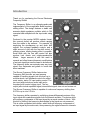
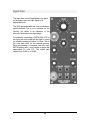
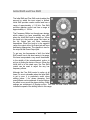
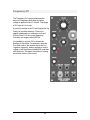
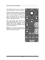
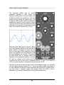
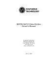
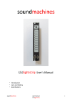
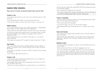
Frequency Shifter
User's Manual
Revision 1.00
February 29, 2004
Encore Electronics 611 Laird Lane. Lafayette, CA 94549 www.encoreelectronics.com
Table of Contents
INTRODUCTION ..................................................................................................3
UNPACKING AND INSTALLATION ....................................................................4
INPUT GAIN .........................................................................................................5
INITIAL SHIFT AND FINE SHIFT.........................................................................6
FREQUENCY CV .................................................................................................7
UP AND DOWN FEEDBACK ...............................................................................8
SINE AND COSINE OUTPUT ..............................................................................9
TROUBLESHOOTING .......................................................................................10
SPECIFICATIONS..............................................................................................11
2
Introduction
Thank you for purchasing the Encore Electronics
Frequency Shifter!
The Frequency Shifter is an all-analog-audio-path
implementation of the sought-after Bode frequency
shifting effect. The design features a stable and
accurate digital quadrature oscillator which is D/A
converted and multiplied with the input audio using
signal.
Produced in the popular MOTM modular format,
this unusual device will produce effects ranging
from the subtle to the extreme. For example, by
employing the simultaneous up and down shift
outputs, the on-board feedback controls, and a
slight amount of shift with the fine-shift control, a
stunning stereo infinite phasing effect is possible.
Small shifts with the fine shift control will also
produce lush vibrato and rotating-speaker-like
effects. Larger amounts of shift can result in
unusual and often bizarre inharmonic modifications
of an input signal that must be heard to be believed.
The frequency shifter can seriously warp any input
signal, from keyboards and guitars to vocals and
drum machines.
The Encore Frequency Shifter features two
Frequency Shift controls, an input preamp
capable of handling signals from line level up to
modular levels, two feedback controls for added
sonic variety, and a CV input scaling control. The
two input jacks include an audio input and a
frequency shift control voltage input. The four
output jacks include upshifted signal, downshifted signal, sine out and cosine out.
The Encore Frequency Shifter is capable of continuous frequency shifting from
0.075Hz up to over 2.3 kHz.
The frequency shifter operates by multiplying phase-differenced versions of the
input signal with quadrature signals from the internal oscillator. The device shifts
all frequency components of the input signal by an equal number of Hertz. With
this kind of shifting, the harmonic relationships in the signal are not preserved.
This is unlike a standard pitch shifter, which shifts all frequency components of
an input signal by the same ratio, thus preserving the signal's harmonic intervals.
3
Unpacking and Installation
We want to remind you to avoid
generating static when handling the
Frequency Shifter (or any electronic
circuit). The frequency shifter comes in a
protective antistatic bag containing a
power cable and four machine screws.
Stand near your synthesizer and touch
the rack frame, a module jack, or other
grounded source to discharge any static.
Open the antistatic bag and remove the
frequency shifter by grasping the
faceplate (avoid touching the circuit
board). Empty the power connecter and
screws from the bag as well.
Make sure your synthesizer power
supply is turned off before installing the
Frequency Shifter. Connect the power
cable as seen above. The cable wires
should be oriented exactly as shown with
the white wire on top and the red wire on
the bottom. The connector should snap
firmly and easily into place. Do not apply
power to the Frequency Shifter until
satisfied that the connector is properly
seated.
Grasp the Frequency Shifter by the
faceplate and install using the four
provided machine screws (or your own
wood screws if you have a wooden
cabinet). Turn the Initial Shift knob to
right or left of center and apply power to your system. The Sine Out and Cosine Out
LEDs should illuminate. The frequency shifter is now ready to use.
4
Input Gain
The Input Gain control (highlighted in the photo
on the right) scales the input signal to an
appropriate level.
The LED associated with this control indicates a
signal overload. This is not a problem for the
circuitry, but rather is an indication of the
amount of distortion in the input stage.
For example, connecting a MOTM 300 VCO to
the Input jack will cause the limit light to come
on around a setting just before 3 o’clock. This is
the unity gain point for the internal preamp.
Since the preamp is powered from the main
MOTM power rails, it can handle a signal that
approaches 15 volts P-P. The actual gain
ranges from -8 dBr to +4.6 dBr.
5
Initial Shift and Fine Shift
The Initial Shift and Fine Shift controls adjust the
amount by which the input signal is shifted.
Initial Shift provides coarse control and has a
range of approximately +/- 2.5 kHz. Fine Shift
provides granular control and has a range of
approximately +/- 100 Hz.
The Frequency Shifter is a through-zero design,
which means you have essentially zero shift
when the Initial Shift knob is straight up. When
the knob is in the positive range, the output at
the Up Output jack will have increasing
frequencies. When the knob is in the negative
range, the output at the Up Output jack will have
decreasing frequencies. The opposite is true for
the output at the Down Output jack.
To get very low frequencies of shift, the Initial
Shift control has to be dead center in its range.
We have incorporated a very small ‘dead-band’
in the middle of the potentiometer’s motion to
aid you in finding the center of the pot. When the
Initial shift is in this dead zone, the Fine Shift
control can be used to adjust the very low
frequency offsets.
Although the Fine Shift control is active at all
times it is most noticeable when the Initial Shift
is set to zero. It is particularly useful when
shifting below 1 Hz, where sweeping, fluid
sound effects can be achieved. At some settings
the effect is very much like phase shifting. Other
settings are reminiscent of Doppler motion. The Sine Out and Cosine Out LEDs
indicate the speed of the shifting effect in this range.
6
Frequency CV
The Frequency CV control determines the
amount of frequency shift when a positive
voltage is applied to the CV IN jack. The range
of CV input is 0 to 5 volts.
A positive increase in the CV will change the Up
Output in a positive direction. There is no
specific relationship (or calibration such as 1
V/Oct) of this CV to the output frequency.
Currently, the range is about 500 Hz.
It is possible to use the CV to reverse the
direction of the shifter. For example, using the
Fine Shift control, the module can be set to a
‘negative’ frequency, and by applying a control
voltage, it will slow down towards 0Hz, and then
shift positively. This has a nice effect of turning
around the motion of the sound.
7
Up and Down Feedback
The Feedback controls are one of the more
important parameters of the Frequency Shifter.
These controls allow a portion of the respective
outputs to be fed back into the input signal. The
effect of this is very hard to describe because it
varies so greatly depending on input signal,
amount of frequency shift, etc. One of the
effects is similar to filter resonance. Others are
just a pure mangling of the sound.
With a typical input signal, excessive (or
overloading) feedback may occur at knob
settings greater than approximately the 2 o'clock
position. This will vary depending on the
combination of feedback control position and the
amount of frequency shift.
Warning: You may experience auditory pain if
these controls are used in combination with loud
amplification. Please be cautious!
8
Sine and Cosine Output
The Frequency Shifter uses an internal
quadrature oscillator to help achieve the
frequency shifting effect. As shown below, this
oscillator produces two waveforms (sine and
cosine) that are exactly 90 degrees apart. The
Frequency Shifter makes these two waveforms
available as outputs to use in a variety of ways.
The Sine Out and Cosine Out knobs control the
amplitude of the signals at the associated output
jacks. The maximum output level is 15V p-p.
When the Initial Shift control is above or below
zero, the Frequency Shifter can be used as an
audio oscillator by taking the output from the
Sine or Cosine jacks. (The outputs from the two
jacks sound identical. The only difference is that
they are 90 degrees out of phase.) You can use
the Initial Shift knob to manually control the
frequency of the quadrature oscillator, or use the
CV input for voltage control (make sure the
Frequency CV knob is not at zero). Remember that the CV input is not scaled to
1v/oct, so it won’t respond to a keyboard the same way as a VCO.
The Sine and Cosine outputs are most useful in the subaudio range. You can drive
VCAs for signal panning, sweep VCFs, or control any other module that accepts a
CV input. Because the sine and cosine waveforms are derived from a digital source,
you may notice a “stepped” quality when driving VCOs and VCFs. If this is
bothersome, you can use a slew limiter to smooth the waveforms out.
9
Troubleshooting
Issue: Why is the Input Gain LED stuck on?
There are two reasons for this condition and both should be corrected for proper
operation. The first is that the Input Gain is set too high for the current input signal.
The second reason might be the feedback. There are two feedback paths from each
output to the input stage. Depending on the signal level and the amount of feedback,
the Frequency Shifter can easily self oscillate and the feedback should be turned
down (counter-clockwise) until the condition goes away.
Issue: I see the Sine Out and Cosine Out LEDs flashing but I don’t hear anything?
These two LEDs represent the full signal level before it reaches the two attenuators.
If you turn the Sine Out control fully counter-clockwise, you are turning down the
signal all the way to zero while the LED continues to show the cycle of the oscillator.
Simply turn the control clockwise to hear the Sine Out signal (Same thing for the
Cosine Out control)
Issue: I hear the Down Output going up, what’s up with that?
A natural side effect of a frequency shifter is to mirror everything around zero Hertz.
On the Down output, when a signal is being modified and moved towards zero Hertz,
it eventually gets to zero and the frequency ‘reflects’ and starts becoming positive.
Issue: The Coarse knob isn’t perfectly straight up when in the dead band, why?
The dead band is a convenient way for you to find zero offset. This allows the fine
shift knob to be better utilized around the lowest frequencies. In the current
implementation, this dead band is around the electrical center of the pot, which may
or may not be the exact physical center of the pot. One way to fix it is to make a
slight adjustment to the knob. (It is a D-shaft, but a few degrees of movement is
possible by loosening the knobs with a 1/16” hex wrench.
The other way is a software adjustment we plan on implementing in the future.
10
SPECIFICATIONS
Microprocessor:
Atmel: AT90S8535 8-bit RISC
Internal clock:
8 MHz
D/A converter:
12 bit dual DAC – BB DAC7612
Analog Multipliers:
Analog Devices AD633JR
Output impedance:
< 1k ohms
Input impedance:
>13k ohms
Local Oscillator output voltage:
+15 V p-p
CV Input range:
0 to 5V
Frequency shifting range:
+/- 0.075 Hz to 2.3kHz
General
Power requirement: +15V @ 45mA
-15V @ 20mA
Size:
2U x 5U
Depth behind panel: 1.5 inches
11