1
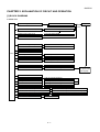
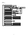
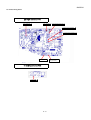
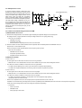
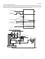
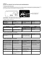
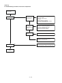
12KHR-N
CHAPTER 2. EXPLAMATION OF CIRCUIT5GTXKEG/CPWCN
AND OPERATION
12KHR-N
[1] BLOCK DIAGRAMS
1. Indoor unit
DC power supply circuit
Rectification circuit
AC power
3.15A
Fuse
Fan motor PWM control circuit
Indoor fan motor
Rotation pulse input circuit
Fan motor pulse detect
AC clock circuit
Remote controller signal reception circuit
Wireless remote control operation
Buzzer drive circuit
Audible operation confirmation
CPU reset circuit
CPU
CPU oscillator circuit
Room temp. detect circuit
Room temp. thermistor
Heat exchanger pipe thermo circuit
Heat exchanger pipe thermistor
EEPROM
Louvre angle, fan speed
Select circuit
Wireless, preheat, Model select
Serial I/O circuit
Indoor/outdoor control signal I/O
Unit-unit wiring
(AC power and
serial signals)
Auto restart circuit
Test run circuit
Test run (forced operation)
Auxiliary mode
Auxiliary mode button ON/OFF
Power on circuit
Self diagnostics, fault diagnosis
Cluster generator drive circuit
Cluster generator
Louver motor drive circuit (Horizontal)
How direction control (Horizontal louver motor)
Louver motor drive circuit (Vertical, right)
How direction control (Vertical louver motor,right)
Louver motor drive circuit (Vertical, left)
How direction control (Vertical louver motor,left)
LED Drive circuit
LED display
2–1