1
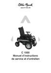
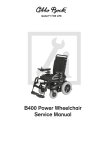
C 1000
Service Manual
Table of Contents
1 Safety ....................................................................................................................................... 3
2 Preface ...................................................................................................................................... 4
3 Required Tools and Maintenance Plan .................................................................................... 4
4 Settings / Retrofit / Replacement ............................................................................................ 7
4.1
4.2
4.3
4.4
4.5
4.6
4.7
4.8
4.9
4.10
4.11
4.12
4.13
4.14
4.15
4.16
Control Panel ........................................................................................................ 7
Battery / Fuse ..................................................................................................... 15
Side Panels ......................................................................................................... 16
Lighting ............................................................................................................... 18
Standard Seat .................................................................................................... 20
Contoured Seat ................................................................................................... 21
Recaro Seating Systems ..................................................................................... 23
Seating System Options ...................................................................................... 25
Covering Parts .................................................................................................... 26
Footrests ............................................................................................................. 27
Front Wheels ...................................................................................................... 29
Caster / Caster Fork ........................................................................................... 30
Frame / Drive Unit Sustainer / Motors ................................................................. 33
Control Unit ......................................................................................................... 38
Electric Options ................................................................................................... 39
Accessories ........................................................................................................ 42
1
C1000 Power Wheelchair
Standard seat backrest
Standard seat with seat cushion
Armrests with clothing protectors
Rear lights
Control panel
Frame
Module
Footrests
Lateral motor cover
2
Front lights
Battery case
1 Safety
Observe the following guidelines for maintenance or repair work:
Use appropriate tools.
Wear appropriate clothing, including gloves and safety glasses, if necessary.
Secure the product to prevent it from tipping over or falling off the workbench.
Read the service and maintenance instructions before starting.
Familiarize yourself with the functions of the product. If you are not familiar with the product, read
the instructions for use manual before inspecting the product.
If you do not have an instructions for use manual, you can order one from the manufacturer (see the
overview of all Otto Bock Branches "Otto Bock Worldwide."). Alternatively, you can download the
document from our home page at www.ottobock.de or www.ottobock.com).
Clean or disinfect the product before starting inspection. See the instructions for use manual for
care instructions or specific product inspection information.
Many of the screw fastenings use thread lock or nylock nuts. If you have to undo such screw
fastenings, replace the nut or screw with a new thread lock and/or nut. If new screws or nuts with
thread lock are not available, use a medium-strength liquid thread lock substance (such as Euro
Lock A24.20).
3
2 Preface
Regular maintenance is important. It increases safety and prolongs the service life of the product.
All rehab products should be inspected and serviced once a year.
If the product is used frequently, or if it is used by growing children or patients with changing clinical conditions,
we recommend readjusting and servicing the product every 6 months.
Use only original spare parts for all service and maintenance.
The service and maintenance described in this manual should be performed by skilled specialists only and not
by the user.
This service and maintenance manual refers to the spare parts catalogs and instructions for use manuals for
the products described here. For this reason, it is important to use these documents together.
Use the maintenance plans (check list) as a template for making copies. Retain completed maintenance plans
and provide the customer with a copy.
3 Required Tools and Maintenance Plan
The following list ensures that you use the right implement for every procedure.
Reversible ratchet handle wrench
and sockets, sizes 8 mm - 20 mm
Allen wrenches,
sizes 2.5 mm - 8 mm
Wrenches, sizes 8 mm - 24 mm
Water pump pliers DIN 8976,
gripping width up to 32 mm
Screwdrivers,
blade widths 2.5/3.5/5.5 mm
Phillips head screwdriver, size 2 mm
Plastic hammer
Hammer approx. 300 g
Pin punch ø 3 mm
4
Side cutting pliers
Liquid thread lock "medium
strength"
Hand drill
Twist drills Ø 4 mm, Ø 5 mm
Stanley knife with sickle hooked
blade
Brush and standard grease
5
Maintenance Plan
for Annual Service
Item
Customer:
C1000
Inspection (check list)
Component (group)
1.)
Function / setting
1
Control unit
- Electronics
2
Battery
3
Frame
- Liquid level
- Battery case
- Cables
4
Lighting
5
Rear wheels
6
Driving wheels
7
Standard seat
8
Recaro seating systems
9
Seating system options
10
Footrest
11
Control accessories
12
Electric additional modules
13
Side panels
14
Accessories
Maintenance performed by:
6
- Spring system
- Drive unit sustainer
- Motor
- Oscillating cranks
- Brake release
- Anti-tippers
- Cables
- Light holders
- Lamp housings
- Lamps
- Cables
- Caster fork
- Spring system
- Caster swivel lock
- Tires
- Tires
- Upholstery
- Seat and back frame
- Seat plate
- Side panel attachment device
- Seat brackets
- Seat lock
- Underframe
- Seat modules
- Seat brackets
- Seating shell interface
- Abductor
- Headrests
- Footrest receiver
- Footplate
- Footrest holder
- Control panel holder
- Joystick
- Tray
- Attendant control
- Suck/blow control
- Chin control
- Environment control
- Electric back angle adjustment
- Electric seat tilt
- Electric lift seat
- Arm pads
on:
2.)
Damages /
deformations
3.)
Screw connections
4 C1000 Settings / Retrofit / Replacement
4.1 Control Panel
Like the B600, the C1000 has two different control
panels: the Delta control panel and the MCS control
panel. Both control panels are attached to the control
panel holder in the same way (see next photo).
Two screws are used to attach the control panel
holder to the underside of the control panel.
Note: The standard control panel cannot be used if the C1000 has more than three electric options.
Control Panel Holder
All control panel holders for the C1000 are attached to the armrest beneath the armrest pad. To mount or
replace a control panel holder, first unscrew the control panel. Next, take the side panel out of its holding
device. After loosening the three set screws, you can either change the position of the control panel holder or
completely remove it.
7
All control panel holders and LCD holders are attached to the C1000 in the same way.
All holders are clamped to the underside of the armrest pad with an iron rail.
Standard control panel holder for MCS and Delta control
panel
Holder for indicator module
Control panel holder, downwards adjustable, MCS and
standard
Holder for LCD standard, swing-away
Holder for LCD, swing-away, height and angle adjustable
Holder for LCD with gooseneck
8
Control panel holder, swing-away in parallel, MCS and
standard
Protective Bow
The protective bow is mounted beneath the control panel. Attach it to the underside of the control panel
holder and use the two screws and the toothed lock washers to fasten it into place.
9
Attaching the Attendant Control
On the C1000 standard seat, the attendant control is mounted to the cross tube of the backrest. The
attachment plate provided is screwed into the two bore holes located here. The holder for the attendant control
is screwed to this attachment plate and the attendant control is then screwed to the holder.
On a Recaro® seat, remove the headrest and put the metal bars of the headrest through the two holes on the
control panel holder.
Two set screws can be used to set the width of the holder.
4.2 Battery / Fuse
Note: Before doing any maintenance on batteries, please read the battery manufacturer's
warnings!
Battery
The standard version of the C1000 includes two 12 V lead acid batteries with a capacity of 60 Ah. During
the charging process, the water acid mixture is converted into gas for a short time. The liquid level should be
checked on a weekly basis and be topped up as needed.
To access the batteries of the C1000, first remove
the footrests or swing them to the side. Then release
the battery case by slightly pulling up the lever on the
lower front part of the battery case.
10
Now you can pull out the entire battery case.
Open the battery strap and remove the cover.
You can now service the batteries as needed.
Battery Charging
First connect the battery charger to the charging receptacle, which is located in the side covering.
Next, connect the battery charger to the mains. Charging starts automatically. LEDs indicate the charging
status on the charger. On the control panel, the charging status is indicated by an increasing number of
LEDs.
Battery charger indicators:
- Yellow LED is lit
= Battery is charging
- Green LED is lit
= Battery is fully charged
- Yellow LED is flashing = Error! Defective battery, connection insufficient ...
- No LED is lit
= No power supply, defective battery charger
11
The battery charger features a programmed
recharging phase. Once a discharged battery is
completely charged (after approximately 8 hours), the
battery charger can remain connected with no risk
of overcharging or damaging the battery. When the
battery has finished charging, disconnect the battery
charger from the mains and then from the wheelchair.
Before the C1000 can be used, the wheelchair
control must be switched off and on.
To charge the battery, plug the 4-pole plug into the
charging receptacle of the C1000. The charging
receptacle is located in the side covering of the
C1000 and is protected by a rubber cover.
Important:
- If possible, do not charge the battery if the green LEDs of the battery indicator are lit. Charge the battery as
soon as the red LEDs begin to flash.
- The warranty becomes void in the case of damages resulting from a completely discharged battery!
- If the C1000 is not used over extended periods of time, it must be charged once a month.
- Only use the battery charger provided by Otto Bock.
Explosive gases can develop while the batteries are charging. For this reason, make sure that the gases can
escape easily. Do not smoke near the battery charger or while handling the batteries. Avoid fire and sparks!
Do not cover the vent slots.
Installing and Removing Batteries
To install or remove the batteries, pull out the battery case.
Proceed as described at the beginning of this section.
12
Removing / Replacing the Battery Case
First remove the fuse, then the battery. The fuse is
located in a small box on the front wall of the battery
case (see page 14). Disconnect the battery and
remove the battery from the battery case. To install a
battery, follow the steps described above in reverse
order.
To remove or replace the battery case, first pull out
the drawer. You can now remove the batteries and
then replace the battery case. Before doing this, make
sure that all connections between battery, motor and
module have been disconnected. A 13 mm ring wrench
or open-end wrench is required for connecting or
disconnecting the batteries.
Note: Before you perform any maintenance work on the batteries, the main fuse must be disconnected!
Always use insulated tools when working on the batteries!
When positioning new battery cables, lead them
through the hole at the rear side of the battery case
and connect the batteries.
You require a 13 mm ring wrench or open-end wrench
for connecting the batteries.
Be sure to connect the battery poles (positive and
negative) correctly.
Attention! Danger of electric shock. Use only
insulated tools.
Once you have connected the two batteries, lead the
two ventilating hoses to the front and put them through
the two small holes in the battery case. To remove the
batteries, follow these steps in reverse order.
Next, reinstall the fuse and put the cover on the battery
case. Finally, secure the cover with the battery strap
and push the battery drawer under the seat. Make
sure that the battery drawer snaps into place.
13
Replacing / Installing the Fuse
To install or replace the fuse, pull out the battery case
and remove the cover as described in the previous
sections. The fuse is located in a small box at the front
of the battery case. Once you have opened the box,
the fuse can be easily pulled out or inserted.
14
4.3 Side Panels
Changing the Position of the Side Panels
Replacing and Setting the Side Panels
A side panel attachment device is located on the left
and right sides of the seat frame.
By loosening the two set screws you can change the
position of the side panels. Once you have found the
correct position, simply retighten the two set screws
using a 3 mm Allen wrench.
To replace the whole side panel, simply loosen the
thumb screw located on the bottom side of the panel
attachment device. Above this screw, there is a set
screw for setting the armrest height. Loosen this screw
using a 3 mm Allen wrench, adjust the armrest to the
desired height and retighten the screw.
The clothing protector is attached to the side panel with
two screws. Loosen these two screws to replace the
clothing protector or to change its position.
Replacing the Arm Pads
Replacing / Retrofitting the Arm Straps
The arm pad of the side panel is attached to the rod
assembly of the side panel with two set screws.
Loosen these two screws to move the arm pad into
a more comfortable position for the user. The third
set screw, which can be seen at the right in the
photograph above, is used for clamping the control
panel holder.
This control panel holder is usually long, and the
additional clamping point prevents it from slipping or
wobbling.
Proceed in a similar manner when replacing the arm
pads for Recaro® seats.
The arm strap must be anchored in the armrest rail.
Insert the metal plate into the rail and move it to the
desired position. Then put the two ends with the
eyelets onto the set screw and secure the connection
with a nut.
15
4.4 Lighting
Replacing Defective Lamps
To change the halogen lamp of the front light, lightly
push the black engaging lever at the lower end of the
lamp. Now the pane and lamp can be folded forward
and removed.
Hold the lamp by the lock ring, pull it back and
replace it with a new one.
When installing the lamp, make sure that the notch on
the lamp socket is positioned correctly.
For replacing the front direction indicators, it is
best to use a small flathead screwdriver. Insert
the screwdriver into the notch at the bottom of the
housing and turn it a quarter turn to the left or right.
This will make the pane come loose from the housing
so you can replace the lamp.
To reattach the pane, place it on the housing the right
way around and press it down firmly.
To replace defective rear lamps, first remove the
upper part of the rear covering, which is secured with
a thumb screw and a hook and loop strap.
Once you have undone this connection, you can
easily lift the covering and disconnect the lamps.
Once you have removed the rear covering and
disconnected the lamps, you can disassemble the
lighting units. Each of these units is attached to the
covering with an Y-shaped holder. Once you have
disassembled the lighting units, you can also remove
the lamp housing and replace the defective lamp. You
need an 8 mm wrench to loosen the screws on the
lighting unit.
Note: When reinserting the panes, make sure they are seated correctly on the housing and ensure that the
screws are firmly tightened. Do not expose the lamps to moisture!
16
Attaching the Front Lights
The front lights of the C1000 are attached to the
frame by a metal sheet.
There are two pre-drilled holes on the underside of
the front part of the frame for attaching the metal
sheet. Apply the two screws and tighten them using a
Phillips head screwdriver.
Screw the lighting unit to the metal sheet using a
6 mm Allen wrench and a 13 mm open-end wrench.
17
4.5 Standard Seat
Replacing the Bearing Plate
To replace the bearing plate, loosen the three screws
next to the arrows in the photograph above. The
screw in the middle of the plate serves as stop for the
back angle adjustment.
You require a 6 mm Allen wrench and a 13 mm openend wrench.
Back Upholstery
To replace or readjust the back upholstery, pull the
back upholstery completely off and readjust the hook
and loop straps.
To replace the upholstery completely, you must first
attach the hook and loop straps to the back frame.
Replacing the Seat
The seat frame of the C1000 can be replaced by
completely disassembling the seat.
Next, loosen the screws of the front seat brackets and
remove the seat frame.
To change the seat frame, you have to remove the
back part first. To do this, loosen the two screws on
each side and remove the back. A 6 mm Allen wrench
and a 13 mm open-end wrench are required. You can
now easily remove the seat plate and the side panel
attachment devices. Also untie all cables connected
to the seat frame by cable ties.
Note: Be careful not to damage any cables
attached to the seat frame!
18
To reassemble the seat, follow the above steps in
reverse order.
See also the sections on the seat plate, side panel
attachment device and back.
Replacing the Seat Plate
Changing the Seat Height (standard seat)
Only standard seats have a seat plate.
To replace the seat plate, simply remove the seat
cushion and then pull out the seat plate with a tug.
To remount the plate on the seat frame, hook the rear
end behind the two spacers located at the end of the
seat frame and push the seat plate firmly into place.
To change the height of the C1000 standard seat,
you have to replace the seat brackets.
There are two brackets at the rear, one on the left
and one on the right, and both are attached with two
hexagon socket head screws.
Setting the Seat Inclination
(For standard seats without electric seat tilt)
There are also two brackets at the front, one on the
left and one on the right, both of which are attached
to the frame with clamping brackets.
You can now remove the seat frame, separate the
seat brackets from the seat frame and replace them.
To reassemble the seat frame with the new brackets,
follow the above steps in reverse order.
Note: When removing the seat, take care not to
damage the cables attached to the seat frame!
The two front seat brackets are used for setting the
seat inclination. These brackets have several bore
holes on their lower end. You can change the seat
inclination by using a different bore hole as follows:
Upper bore hole 0°, middle bore hole 3°, or lower bore
hole 6°. To do this, loosen the screw connections that
connect the seat brackets to the adjustment brackets.
Push the seat unit up or down to the desired seat
inclination. Once you have found the desired position,
screw the two brackets together.
19
4.6 Contoured Seat
The contoured seat is attached to the seat plate with
a hook and loop strap.
You can mount the contoured seat on the frame of
the standard seat.
20
Attach the back of the contoured seat to the
wheelchair backrest with 6 clamps.
4.7 Recaro Seat
Replacing the Underframe
To access the underframe of the Recaro® seat, you
have to remove the seat first. To do this, pull the lock
located underneath the seat.
Lift the seat slightly and push it backwards. You can
now remove the seat.
Once you have removed the seat, you can unscrew
the seat brackets. The underframe of the Recaro®
seat is attached in the same way as the underframe
of the standard seat (by brackets at the front and
at the rear of the frame). Once you have loosened
these connections, you can remove both parts of the
underframe.
Seat Attachment Device
The seat attachment device of the Recaro® seat is
screwed to the underside of the seat. First unlock
and remove the seat. Place the seat in front of you
and loosen the three screws on each side of the seat
attachment device using an Allen wrench.
21
Replacing Seat Modules
The seat bottoms of the Recaro® seat modules are
attached to the seat frame in the same way as the
complete Recaro® seats and are also disassembled
in the same way.
The modular backrests are hooked onto the seat
bottoms. The seat bottoms have two receivers. First,
attach a retaining washer to the front receiver.
22
Next, hook the backrest onto the seat bottom and
attach the front lock to the second receiver.
4.8 Seating System Options
Assembling / Replacing the Abductors
A receiver is used to attach the abductors to the front
cross brace of the seat frame.
To attach the receiver, first drill a hole into the middle
of the brace using a 6 mm drill bit and then put the
attachment screw for the receiver through this hole.
Once you have attached the receiver, insert the
abductor holder into the receiver and tighten the
screw to fix the abductor in the desired position.
Assembling the Mounting Kit for the Headrest
Attachment
The holding device for the headrest is attached to the
back frame at the top of the back tube. The device is
attached by a screw on each side (right and left).
If you have a round back tube, please indicate this
in your order. You will receive an additional adapter
plate with your order which allows for attachment to
a round tube.
The holes for attachment are pre-drilled.
23
Assembling / Retrofitting Straps and Belts
Four-Way Chest Strap Kit (only for Recaro® seats)
To mount the four-way chest strap kit, you must first
screw the cross bar into the rear of the seat frame.
Screw the cross bar to the rear end of the seat
frame.
Attach the strap end to this tube. There is a bore hole
in the middle of the bar. Bend apart the two eyelets of
the strap end until they fit over the bar. Put the screw
through the eyelets and the bore hole and tighten the
screw.
Remove the protective cap from the rotary knob
located on the backrest.
Remove the back adjustment knob.
24
The covering is attached with three small plastic
nipples. Push them out from the rear side using a
screwdriver and remove the covering.
Once you have removed the covering, you will see
two holes on the top left side of the metal plate.
Re-drill the upper hole using a 4 mm drill bit. This will
allow you to mount the adjustment screws for the
strap.
Attach the two other strap ends to these bore holes
and reassemble the covering and the adjustment
knob.
Pelvic Belt
The pelvic belt is available for all seat variants.
Like the four-way chest strap kit, it is attached to the sides. However, it is not attached to the seat frame on
the rear side.
On standard seats, the belt is attached to the bearing plate with a flap with an eyelet and screwed in.
On Recaro® seats, the pelvic belt is attached to the sides in the same way as the four-way chest strap kit.
Please see the previous section.
25
4.9 Covering Parts
The C1000 has several covering parts at the rear, front and left and right sides of the wheelchair.
Side Covering
Front Covering
The side covering has three attachment points, two at
the top and one at the bottom.
When attaching the covering, make sure that all
cables and plugs are stowed safely behind the
covering and that they are not hindered by the
covering. A 3 mm Allen wrench is required.
The front covering covers the battery case and also
protects it from contamination.
This covering is attached to the frame with four
screws. To tighten or loosen these screws, you need
a 3 mm Allen wrench.
Lower Rear Covering
Upper Rear Covering
The lower part of the rear covering of the C1000
is attached to the Servotronic holding device from
below. The covering is attached using one slotted
screw at the bottom and one plastic clip on the left
and right sides.
The upper part of the rear covering is secured with a
thumb screw and hook and loop strap. To remove the
upper covering, first loosen the thumb screw and then
carefully separate the hook and loop connection. Do
not forget to disconnect the lamps when removing the
covering.
When ordering a new rear covering, please indicate
the following:
- Type of seat being used on the C1000 (Recaro® or standard
seat)
- Seat height of the C1000
- Electric seat functions: seat tilt, lift seat device or
electric back?
26
4.10 Footrests
Different footrest systems are available for the C1000, all offering the same or at least similar setting and
attachment options. This makes the footrest systems easier to service or replace.
Assembling / Replacing the Footplate
Replacing the Mounting Accessories
To disassemble or assemble the footplate of a
standard footrest, you only have to loosen a single
screw.
To replace or mount the mounting kit of the aluminum
footrest, first remove the screw connecting the
mounting kit to the footplate.
Now loosen the two countersunk head screws with
two Allen wrenches and separate the mounting kit
from the footrest tube.
Footrest Holder
Mounting kit components
The footrest holders are attached to the seat frame
with two screws each.
27
Footrest Receiver
Loosen these connections to adjust or completely
remove the footrest holder.
Calf Pad
The calf pad is attached to the footrest tube.
To replace the unit completely, loosen the Allen head
screw on the clamping unit.
28
To replace the footrest receiver, first remove the entire
footrest from the C1000. You can then access the two
set screws at the rear of the receiver more easily.
Loosen these set screws using a 3 mm Allen wrench.
You can now separate the footrest tube from the
receiver or adjust it to another length.
4.11 Front Wheels
To remove a front wheel, first unscrew the protective
cap, which is attached to the wheel with a Phillips
head screw.
Next, remove the 4 wheel screws using a 5 mm Allen
wrench. Tighten these screws to a torque of 20 Nm
when you remount the wheel.
The screw in the middle serves to fix the wheel flange
and can be loosened or tightened using a 19 mm
socket wrench.
Torque: 30 Nm.
For instructions on how to replace the inner tube or
casing, see "Casters" on page 31.
29
4.12 Casters / Caster Forks
The rear wheels of the C1000 are 10" casters. They are connected to the wheelchair's Servotronic steering
system.
Mounting the Caster Forks
The caster forks of the C1000 come pre-assembled.
When mounting the fork, put the track lever onto the
fork and engage it by a quarter turn to the left or
right.
Insert the fork into the caster fork receiver.
Put a washer into the receiver and tighten the fork with
a 19 mm socket wrench. Do not tighten the fork to
snugly, the fork must be able to turn by approximately
180° at a time.
Now attach the black plastic cap to the receiver.
Next, screw the right and left track rods of the
steering motor to the track levers using a 13 mm and
a 17 mm wrench.
30
Replacing / Repairing the Caster
Note: Before mounting or removing a caster, support the frame with suitable objects (e.g. pieces of wood) to
prevent it from tipping over or slipping. The wheel must be able to rotate freely. Use two 4 mm Allen wrenches
for mounting or removing the caster.
To mount the caster, put the axle through the hole in the middle of the caster fork and through the wheel. Tighten
the wheels using two 4 mm Allen wrenches. Make sure that the front and rear wheels are in line.
The casters and steering motor will be adjusted more precisely later using a hand programming device.
Replacing the Casing or Inner Tube of Pneumatic
Tires
Both the front and rear wheels have two-piece rims
which can be separated by removing the screws.
First let the air out of the tire.
Next, unscrew all screws using an Allen wrench.
Once all screws have been loosened, the two parts of
the rim can be separated from each other.
You can now easily replace or repair the inner tube
or casing.
31
Splash Guard for Caster Fork
Repair the inner tube with a standard bicycle repair
kit or replace the tube with a new one.
Caution!
Replace the casing if it is bald or shows cracking or
other damage.
To reassemble the casters, follow the above steps in
reverse order.
32
The splash guard for casters is attached to the
caster fork with two hexagon socket head screws.
A 3 mm Allen wrench is required for replacing this
component.
4.13 Frame / Drive Unit Sustainer / Motors
Disassembling / Replacing the Spring System
The C1000 has two different types of springs: green
and blue.
The green spring has been approved for a maximum
load of 160 kg, the blue spring has been approved for
a maximum load of 200 kg.
The springs are preadjusted to 4.5 cm.
Once you have disassembled everything as described
in the previous sections, you can start disassembling
the frame parts.
The springs are located on the side of the drive unit
sustainer, behind the wheels.
Install the springs as shown in the photo. Hold the
spring between the bracket on the drive unit sustainer
and the pre-drilled hole in the oscillating crank. Put a
washer between the screw head and the bracket and
tighten the screw.
A 6 mm Allen wrench and a 13 mm wrench are
required.
Splasher for Driving Wheels
To attach the splashers of the two driving wheels,
first place a metal sheet in the splasher. The metal
sheet and the splasher each contain three bore holes.
Position the holes over one another and put a screw
through the upper hole from behind and secure the
screw with a cap nut.
The two upper screws of the motor suspension are
used for attaching the splasher.
Loosen and remove the two upper screws, apply the
splasher and reapply the two screws.
Note: Do not forget to secure the wheelchair to
prevent it from slipping or tipping over. Support the
C1000 so that the driving wheels are able to rotate
freely and the chair is unable to slip.
33
Removing the Oscillating Cranks
The oscillating cranks of the front wheels are attached to the drive unit sustainer, allowing the cranks to rotate
freely. To remove the oscillating cranks, first remove the wheels, springs and motors.
Then loosen and replace the oscillating cranks using a 20 mm socket wrench. When installing the cranks,
make sure that the spring is attached to one of the three rear bore holes of the oscillating crank. Then attach
the spring to the uppermost bore hole of the drive unit sustainer.
Each motor is attached to the oscillating cranks with 4 screws. As a result, you have to remove the motors
before removing the oscillating cranks.
The oscillating cranks are attached to the drive unit sustainer with one screw.
Motors
When installing the motors in the C1000, make sure
that the right motor is installed on the left side and the
left motor on the right side.
This corresponds to the patient's perspective when
seated in the wheelchair.
To attach the motors to the oscillating cranks, first
tighten the lower screws using a 6 mm Allen wrench.
34
Before removing the motors, unscrew the brake
release.
Brake Release
Brake Settings
Correct brake settings are essential for safe driving.
For this reason, the brake/wheel lock should be
inspected every three months. Repairs and settings
must only be made by specialists.
Attention: Incorrect settings can lead to brake
failure, which can result in fatal accidents.
To avoid excessive friction, the radius of the brake
cable must not be less than 10 cm. Damaged brake
cables must be replaced immediately (if individual
wires are protruding or there is a kink in the black
sheath, for example). Please contact your dealer.
The brake release is attached to the right side of the
C1000 with the wheelchair lying on its side, as shown
in the photo.
When attaching the brake release, make sure that the
short cable is under the longer cable. The cable for
the left side is routed behind the battery case.
A 6 mm Allen wrench is required for tightening the
attachment screw.
Put a black plastic cap on the screw head.
Release bolt
Adjustment screw
1
2
3
Brake release lever
Functional Test of Brake Settings
• The release lever must be locked in position 1.
• While driving straight forward at approximately
6 km/h, release the joystick in its front-most
position.
• If the wheelchair keeps rolling straight forward
while decelerating, repeat the test on a descending
slope with an inclination of 10% (unless the type
plate states that this is not permitted).
• If the wheelchair does not continue straight forward,
but instead turns to the right or left, the brake cable
for the opposite side must be readjusted. This
adjustment is described in items a and b in the next
section.
• If the wheelchair continues to roll straight forward
in both cases, perform the following test on level
ground.
Lever position
1. Drive mode
2. Not permitted while in drive mode
3. Push mode
• Pull the release bolt on the brake housing. The
lever automatically moves forward into position 2.
You should not be able to push the wheelchair with
the lever in this position. If the driving wheels do not
block, slacken the brake cable for the side with the
rotating wheel by 1⁄2 turn (see page 38, items a and
b).
• Turn the lever to position 3. The wheelchair can be
pushed easily, even when turning. If the wheelchair
pulls to one side, increase the tension of the brake
cable on the appropriate side. This adjustment is
described on page 38, items c and d.
• If no deviations are found during the tests described
above, no readjustment is necessary.
35
Adjusting the Brake Release
Tools required:
- 3 mm Allen wrench (for the covering)
- 8 mm open-end wrenches (2)
For a better overview, remove the side covering.
After each adjustment, the adjustment screw must
be secured with the counter nut. We recommend
proceeding in small increments (1⁄2 turn).
Adjusting a taut cable
a. Loosen the counter nut M5 (8 mm wrench) and
turn the adjustment screw clockwise into the
brake release housing.
b. Perform the functional test again.
Adjusting a slack cable
c. Loosen the counter nut M5 (8 mm wrench) and
unscrew the adjustment screw (counter-clockwise)
from the brake release housing.
d. Perform the functional test again.
This adjustment is carried out on the brake release
housing. If the adjustment paths on the adjustment
screw are insufficient, you can shift the threaded
bar (7 mm open-end wrench) at the other end of
the cable by approximately 5 - 8 mm. You must
then completely readjust the brake release. If you
are making adjustments for the first time (e.g. cable
replacement), the cable should have very little play
when you begin adjusting it.
Frame and Drive Unit Sustainer
The frame of the C1000 is placed on the drive unit
sustainer and secured with two screws on each
side.
Apply the screws as shown in the photograph
above.
The two holes in the middle will be used later for
attaching the seat brackets.
A 6 mm Allen wrench is required for tightening the
screws.
36
For reinforcement, a steel rail is mounted to the drive
unit sustainer under the supporting surface of the
frame. The rail is attached using the frame screws.
Tighten the first two screws and then mount the seat
brackets. Fasten each bracket with two screws. A
6 mm Allen wrench is required.
Once you have tightened all 4 screws on each side,
use a plastic hammer to apply a black plastic cap to
each screw head.
Replacing the Drive Unit Sustainer
Disconnect all plugs and make sure the wheelchair
is switched off. In order to replace the drive unit
sustainer, all screws connecting the frame to the
drive unit sustainer must be loosened. In the case
of Recaro® seats, first remove the seat and then
disassemble the seat frame. In the case of standard
seats, you can remove the seat and seat frame in a
single step.
Remove all other components attached to the frame
and drive unit sustainer, such as the brake release,
covering parts, modules, footrests, wheels, motors,
etc. You can now separate the seat frame from
the drive unit sustainer. When disassembling the
motors, make sure that the wires of the brake release
have been disconnected. Information on all these
components is provided in previous and subsequent
sections.
Note: Some components are very heavy, such as
the battery, frame, seat, motors, etc. When removing
such components, lift them safely to avoid injury.
37
4.14 Control Unit
For C1000 models with no more than three electric
options, the standard control module is sufficient.
Connections:
- Right connection (in driving direction): Servotronic
- Left connection (in driving direction): light; white /
yellow = left side; blue/ red = right side
- Right round jack (in driving direction): charging
receptacle
- Left round jack (in driving direction): connection
to control panel or additional module
Attach the control box to the rear side of the drive unit
sustainer with two screws.
Connect all plugs, attach the protective cover and
screw in the cover on the left and right sides with a
Phillips head screw.
If the C1000 is equipped with more than three electric
options, the additional module is required.
The module is mounted on a metal rail (see the
photograph above).
The metal rail is then mounted to the seat frame and
fastened with screws on the left and right sides.
38
4.15 Electric Options
All electric options are offered as complete component groups. As a result, it is not necessary to assemble
individual parts. The complete component groups only have to be attached to the frame and connected to the
electronic system.
Electrically Adjustable Footrest
Insert the electrically adjustable footrest along
with the holding device into the footrest holder and
connect it to the appropriate module. Lead the cables
closely along the frame or drive unit sustainer and
fasten the cables with cable ties in several places.
The connector for the footrest plug should rest right in
front of the footrest holder.
Electric Lift Seat
The frame of the C1000 lift seat is attached to the
frame with seat brackets, just like the frame of the
standard seat.
The attachment at the front is also the same as the
attachment for the standard seat.
39
Lead the cables for the lift seat to the control box.
Fasten the individual cables together every 10 cm
using cable ties.
Make sure that cables will not be hindered when the
seat lift function is used.
The lift seat has a contact which tells the motor when
the end position has been reached so the motor can
switch off automatically. The distance between the
two contact points should not exceed one millimeter.
If necessary, the upper contact point, consisting of a
set screw, can be readjusted.
Seat Tilt
Lift Seat with Seat Tilt
Like the normal seat frame, the tilt frame is attached
to the frame at the front and rear with seat brackets.
Make sure that the countersunk head screw
connecting the seat bracket to the tilt frame is level
with the inner side of the tilt frame. The seat bottom is
mounted in the same way as with the standard seat
or Recaro® seat.
When positioning the cables, make sure that they will
not be hindered when seat tilt function is used.
The lift seat device with seat tilt can only be ordered
as complete component group. If you have ordered
a lift seat with seat tilt, the tilt frame comes welded
to the frame of the lift seat. See the lift seat section
for instructions on mounting it to the frame. This
component group is also mounted to the frame with
seat brackets.
40
Before operating the seat, make sure that the spring
is hooked to the lift frame.
Lead the cable backwards as shown in the photo
and fasten the cables approximately every 10 cm with
cable ties.
Make sure that cables will not be hindered when the
lift seat or seat tilt functions are used.
For instructions on adjusting the contacts of the limit
switch, see the lift seat section.
Electric Back Angle Adjustment
The electric back angle adjustment is also offered as
complete component group.
The electric back angle adjustment component
group includes a backrest containing the receivers
for the motor. Like the standard back, this backrest
is mounted to the seat frame with the bearing plate.
Insert the motor as shown in the photograph and lock
it at the top with bolts.
At the lower end, the bolt must snap into the
receiver.
41
4.16 Accessories
Joystick Accessories
To mount joystick accessories, first pull off the upper
end of the joystick. A pin is exposed. Here you can
mount accessories such as a fork for tetraplegics, a
golf ball or a stick, etc.
Fix the accessory component by tightening the set
screw.
Crutch Holder
The crutch holder of the C1000 is mounted to the side
panel on the underside of the arm pad.
The crutch holder is screwed into two bore holes in
the arm pad.
Rear-View Mirror
The rear-view mirror of the C1000 is mounted to the
rail of the control panel holder and must be adjusted
for individual users.
42
Hersteller/Manufacturer:
Otto Bock HealthCare GmbH
Max-Näder-Straße 15 · D-37115 Duderstadt
National: Telefon (0 55 27) 848 1461/1462/1463 · Fax (0 55 27) 848 14 60
International: Phone +49-5527-848-1304/1562/1590/1594/3663 · Fax +49-5527-848-1676
e-mail: [email protected] · Internet: http://www.ottobock.com
Otto Bock HealthCare GmbH
Lindenstraße 13 · D-07426 Königsee
Otto Bock HealthCare GmbH has been certified by the German Society for the Certification of Quality Assurance Systems (DQS)
in accordance with DIN EN ISO 9001 standard, reg. no. 779 (management system)
© Otto Bock · 647G213=GB – 07.04/1
Versandanschrift für Rücksendungen/Address for Returns