1
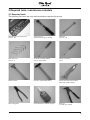
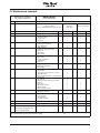
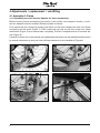
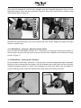
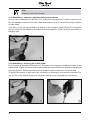
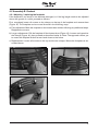
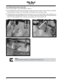
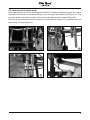
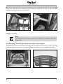
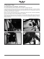
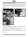
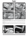
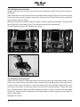
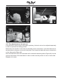
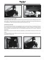
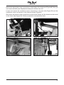
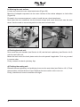
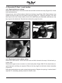
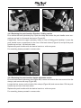
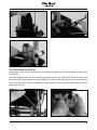
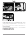
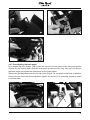
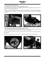
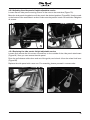
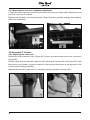
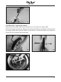
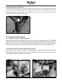
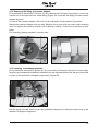
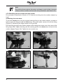
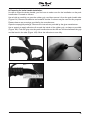
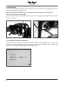
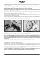
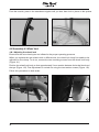
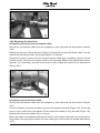
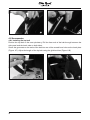
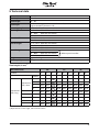
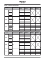
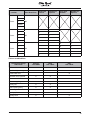
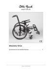
BRAVOracer
Service Manual
Service Manual for the BRAVO Racer Active Wheelchair
Table of contents Page
1 Introduction........................................................................................................................3
1.1 Foreword......................................................................................................................3
1.2 Technical support........................................................................................................3
1.3 Explanation of symbols...............................................................................................3
2 General safety instructions................................................................................................4
3 Required tools, maintenance schedule.............................................................................5
3.1 Required tools.............................................................................................................5
3.2 Maintenance schedule................................................................................................7
4 Adjustments / replacement / retrofitting...........................................................................8
4.1 Assembly A: Frame.....................................................................................................8
4.1.1 Retrofitting the multi-function adapter for frame accessories.......................................... 8
4.1.2 Retrofitting / replacing / adjusting the tip-assist............................................................. 9
4.1.3 Retrofitting / replacing the anti-tipper.............................................................................. 9
4.1.4 Retrofitting / replacing / adjusting the transport wheels............................................... 10
4.1.5 Retrofitting / replacing the crutch holder....................................................................... 10
4.2 Assembly B: Footrest................................................................................................ 11
4.2.1 Adjusting / replacing the footplate................................................................................. 11
4.2.2 Adjusting the lower leg length........................................................................................ 12
4.2.3 Adjusting the footplate angle......................................................................................... 13
4.2.4 Replacing / retrofitting the lateral heel blocks on the footplate . ................................. 14
4.3 Assembly C: Seat......................................................................................................15
4.3.1 Replacing the seat upholstery / upholstery bars........................................................... 15
4.3.2 Replacing / removing the adjustment tube.................................................................... 16
4.3.3 Vertical seat adjustment................................................................................................. 16
4.3.4 Horizontal seat adjustment............................................................................................. 17
4.3.5 Adjusting the seat angle................................................................................................. 18
4.3.6 Adjusting the seat depth................................................................................................. 18
4.3.7 Fine adjustments to the back unit.................................................................................. 19
4.3.8 Adjusting the seat width................................................................................................. 20
4.4 Assembly D: Back / push handles...........................................................................23
4.4.1 Replacing the back release............................................................................................ 23
4.4.2 Replacing the back release spring................................................................................. 23
4.4.3 Replacing the push handles: Standard / folding version............................................... 24
4.4.4 Replacing the push handles: Height-adjustable version................................................ 24
4.4.5 Retrofitting the push bar................................................................................................. 25
4.4.6 Replacing the back upholstery....................................................................................... 26
4.4.7 Pre-adjusting the back angle.......................................................................................... 27
4.5 Assembly E: Side panels..........................................................................................28
4.5.1 Adjusting the side panels: Clothing protector version.................................................... 28
4.5.2 Replacing the side panels: Clothing protector version.................................................. 28
4.5.3 Adjusting the side panels: Height-adjustable version.................................................... 29
4.5.4 Replacing the side panels: Height-adjustable version................................................... 29
4.5.5 Replacing the arm pad / lengthwise adjustment........................................................... 30
4.6 Assembly F: Casters.................................................................................................30
4.6.1 Replacing the caster axle................................................................................................ 30
4.6.2 Removing / replacing the casters.................................................................................. 31
4.6.3 Replacing the caster forks.............................................................................................. 32
4.7 Assembly G: Rear wheels.........................................................................................32
4.7.1 Centre of gravity and seating position............................................................................ 32
4.7.2 Replacing the rear wheel attachment assembly............................................................ 32
4.7.3 Replacing the fitting and camber adapter...................................................................... 33
4.7.4 Installing a wheelbase extension.................................................................................... 33
4.7.5 Retrofitting the rear wheels with drum brakes............................................................... 34
4.7.6 Adjusting the quick-release axle..................................................................................... 36
4.7.7 Changing tyres................................................................................................................ 37
4.7.8 Replacing the push rings – narrow / wide mounting position........................................ 37
4.7.9 Replacing / retrofitting spoke protectors........................................................................ 37
4.8 Assembly H: Wheel lock...........................................................................................38
4.8.1 Adjusting the wheel lock................................................................................................. 38
4.8.2 Replacing the wheel lock................................................................................................ 39
4.9 Accessories...............................................................................................................40
4.9.1 Installing the lap belt....................................................................................................... 40
5 Technical data..................................................................................................................41
1 Introduction
1.1 Foreword
Regular maintenance is important – it improves the safety and increases the lifespan of the
product.
All mobility products should be inspected and serviced once a year.
If the product is frequently used, or if it is used by growing children or patients with changing
clinical conditions, we recommend readjusting and servicing the product every 6 months.
Only use original spare parts for all service and maintenance.
The service and maintenance tasks described here should only be completed by trained, qualified personnel and not by the wheelchair user.
This service and maintenance manual refers to the spare parts catalogues and instructions for
use for the products described. Please use these documents together.
Use photocopies of the maintenance schedule (checklist in Section 3.2). Retain completed
maintenance schedules and provide the customer with a copy.
BRAVO Racer
Instructions for Use
647G447=D/GB
Spare Parts Catalogue
1.2 Technical support
Your national Otto Bock Team will be pleased to answer your technical questions. Contact addresses and telephone numbers are listed on the last page of this manual.
1.3 Explanation of symbols
Caution!
Personal injury warning.
Attention!
Product damage warning.
Note!
Useful tips for the technician.
Please read!
Please read the Instructions for Use first!
2 General safety instructions
Observe the following guidelines for maintenance or repair work:
Caution!
Use appropriate tools (refer to pages 5 ff.).
Caution!
Wear appropriate clothing, including gloves and protective goggles if required.
Attention!
Secure the product to prevent it from tipping over or falling off the workbench.
Please read!
Please read the service and maintenance instructions before commencing work.
Please read!
You should become familiar with the functions of the product first. If you are not familiar
with the product, read the instructions for use before inspecting the product.
If you do not have a copy of the instructions for use, you can order one from the
manufacturer (see the overview of all Otto Bock branches “Otto Bock Worldwide”).
You can also download documents from our homepage:
www.ottobock.de or www.ottobock.com.
Attention!
Clean or disinfect the product before you start the inspection. Consult the instructions
for use regarding product care or product specific inspection information.
Attention!
The screws and nuts for many of the screw connections are coated with thread lock.
If such screws must be replaced or the connections undone, be sure to use a new
screw or nut coated with threadlock. If new screws or nuts with thread lock are not
available, apply a medium-strength liquid thread lock substance (such as Loctite
241 or Euro Lock A24.20) to the existing screws.
3 Required tools, maintenance schedule
3.1 Required tools
The following list shows the tools and accessories required for service.
Ratchet wrench and socket set,
sizes 8 – 24
Torque wrench,
measurement range 5 – 50 Nm
Wrenches,
sizes 10 – 24
Allen wrenches,
sizes 3 – 6
Screwdrivers, blade widths
2.5, 3.5, and 5.5 mm
Phillips screwdriver,
size 2
Plastic hammer
Hammer, approximately 300 g
Stanley knife with sickle hooked
blade and standard blade
Side cutting pliers
Liquid thread lock “medium strength”
Rivet gun
for rivets up to ø 5mm
Workbench and vice with plastic
jaws and rubber insert
Hand drill
Tyre mounting levers and inner tube
repair kit
3.2 Maintenance schedule
Maintenance schedule
for regular inspections
Item
BRAVO Racer
- active wheelchair -
Inspection (checklist)
Component (assembly)
Serial number:
Customer:
1.)
Function / setting
(refer to 647G447GB Instructions for Use)
2.)
Damage /
deformation
3.)
Screw connections
A
Frame
- Base frame
x
x
Footrest
C
Seat
- Lengthwise setting
- Lower leg length setting
- Angle adjustment
x
x
x
x
x
x
x
B
- Anti-tipper
- Transport wheels
- Crutch holder
- Tip-assist
x
x
x
D
Back / push handle
- Seat upholstery
- Lengthwise adjustment of the
seating unit
- Seat height
- Seat cushion
E
Side panel
F
Caster
G
Frame accessories
Rear wheel
Rear wheel accessories
H
S
Wheel lock
Wheel lock accessories
Accessories
Do the settings of the
wheelchair comply with the
user’s requirements?
x
x
x
x
x
x
x
x
- Back upholstery
- Back tubes
- Folding mechanism
- Push handles
- Push bar
x
x
x
x
x
x
x
x
x
- Tyres (wear)
- Air pressure
- Running characteristics of the wheels
- Threaded axles
- Swivelling characteristics of the wheel forks
x
x
x
x
x
x
x
- Height setting
- Retracting mechanism
- Removability
x
x
x
- Tyres (wear)
- Air pressure
- Running characteristics of the wheels
- Spokes
- Push rings
- Quick-release axles
- Wheel camber
- Rear wheel attachment
x
x
x
x
x
x
x
x
- Spoke protectors
- Wheelbase extension
x
x
- Wheel lock function
- Lever assembly
- Clamp fittings
- Pull-release cables
x
x
x
x
x
x
x
x
x
x
x
x
x
x
x
x
- Wheel lock lever extension
x
x
- Lap belt
x
x
The maintenance service was carried out by:
on:
4 Adjustments / replacement / retrofitting
4.1 Assembly A: Frame
4.1.1 Retrofitting the multi-function adapter for frame accessories
Before mounting frame accessories (tip-assist, crutch holder, and transport wheels), a multifunction adapter must be installed. Please proceed as follows:
First remove the rear wheels by pressing the button on the quick-release axle with your thumb
and pulling off the wheel (Figure 1). Then loosen the cap nuts on the front of the rear wheel
attachment (Figure 2) and remove them completely. Pull the U-shaped section off towards the
rear (Figure 3).
Loosen the counter nut on the top end of the adjustment tube and move the adjustment tube forward
by several centimetres so that you have sufficient clearance for the installation (Figure 4).
1
3
2
4
Now push the hexagonal multi-function adapter past the loosened adjustment tube onto the
exposed hexagon nut on the rear wheel axle (Figure 5). Secure the multi-function adapter using
the clamping screw (Figure 6).
5
6
Reinstall the adjustment tube, rear wheel attachment, and wheels. Repeat the steps described
above in reverse order.
4.1.2 Retrofitting / replacing / adjusting the tip-assist
First, proceed as described in Section 4.1.1. Then press in the spring-mounted push button on
the tip-assist and push the tip-assist onto the multi-function adapter to the desired mounting
position (Figure 7).
4.1.3 Retrofitting / replacing the anti-tipper
First, proceed as described in Section 4.1.1 up to the point where the adjustment tube is loosened.
Now push the pre-assembled anti-tipper onto the exposed rear wheel axle until the anti-tipper
adapter (hexagonal shape) is in place on the hexagon nut of the axle. Secure the anti-tipper using the clamping screw (Figure 8) and test the swing-away and locking functions.
7
8
Note!
Subject to technical changes.
4.1.4 Retrofitting / replacing / adjusting the transport wheels
First, proceed as described in Section 4.1.1. Follow the same process to install a second multifunction adapter across from the rear wheel attachment in order to attach the transport wheels
on both sides.
Then press in the spring-mounted push button on the transport wheel (Figure 9) and push it
onto the multi-function adapter to the desired mounting position. Follow the same procedure on
the other side.
9
4.1.5 Retrofitting / replacing the crutch holder
First, proceed as described in Section 4.1.1. Then press in the spring-mounted push button on the
crutch holder (Figure 10) and push the crutch holder onto the multi-function adapter to the desired
mounting position. Attach the hook and loop strap to hold the crutches to the back tube.
To replace the bucket, loosen the screw connection on the bottom and remove the bucket (Figure 11). Put a new bucket in place and secure it with the screw removed from the old one.
10
10
11
4.2 Assembly B: Footrest
4.2.1 Adjusting / replacing the footplate
If the footplate is too small or has become damaged, or if the leg length needs to be adjusted
due to the growth of a child, proceed as follows:
First, completely loosen all screws on the clamps on the top of the footplate and remove them
(Figure 12). The footplate can be moved forward in the following ways:
a)Fine adjustment: Move the footplate on the footrest bars without following any additional steps.
Retighten the screws.
b)Larger adjustments: Pull the footplate off the footrest bars (Figure 13). Loosen and reposition
the clamps (Figure 14); then proceed as described under a). Note: The approach allows you
to mount the footplate further forward and closer to the frame.
c)Replacement: Loosen all screws on the top and the the clamps. Mount the footplate as described above.
12
13
14
11
4.2.2 Adjusting the lower leg length
The lower leg length can be adjusted as follows:
a)Fine adjustment of the lower leg length: Loosen the outer screws on the clamps that guide
the footrest bars (Figure 15) and adjust the footplate to the desired height.
b)Changing the lower leg length (from long to short or short to long): Remove the footplate, and
then remove the exposed footrest bars. Turn the footrest bars around (Figure 16) and reinstall
them. Put the footplate back in place and retighten all screws (Figure 17).
15
17
Note!
Follow the same process to replace the footrest bars.
12
16
4.2.3 Adjusting the footplate angle
First, loosen the set screws on the clamps that hold the T-shaped crossbrace (Figure 18). Loosen
the centre Allen screws on the same clamps so you can open the rotation joint (Figure 19). Then
open the screw connections located on the frame tube between the clamps (Figure 20).
Now loosen the crossbrace screw connection on the seat tube (Figure 21), so that the nuts can
move freely in the guide groove.
18
20
19
21
13
Move the crossbrace back along the seat tube until the footplate reaches the desired angle
(Figure 22). Use the scale on the bottom of the seat tube (Figure 23) in order to make sure the
footplate is positioned evenly on both sides.
22
23
Retighten all screws.
Note!
On wheelchairs with narrow seats, the footplate is mounted in the centre
(Figure 24).
4.2.4 Replacing / retrofitting the lateral heel blocks on the footplate
The lateral heel blocks are attached to the bottom of the footplate using screws or rivets. You have
to drill the required bore holes. The positions are pre-punched on the footplate (Figure 25).
24
14
25
4.3 Assembly C: Seat
4.3.1 Replacing the seat upholstery / upholstery bars
First remove the seat cushion. Remove the front tube end caps (Figure 26).
Loosen the hook-and-loop connections on the tension-adjustable upholstery in order to slacken
it (Figure 27). Evenly pull the seat upholstery and upholstery bars out of the guides towards the
front (Figure 28) (use pliers if required).
Either re-use the same upholstery bars or replace them with new ones. Insert the upholstery
bars into the loops on the new seat upholstery, if required.
Reinsert the upholstery bars into the guides on the seat tube (Figure 29) and pull them back
evenly. Refasten the hook-and-loop connections on the tension-adjustable upholstery. Reinsert
the tube end caps.
26
28
27
29
15
4.3.2 Replacing / removing the adjustment tube
Remove the rear wheels, rear wheel attachment, and U-shaped component as described under
4.1.1. Loosen the counter nut on the top of the adjustment tube (Figure 30) and remove it. Replace
the adjustment tube, counter nut, or guide bushings with new parts as required (Figure 31).
Remove the guide bushings from the adjustment tube and insert them in the desired position
(Figure 32). Move the U-shaped component to the new position. Follow the same procedure on
the other side.
30
31
32
4.3.3 Vertical seat adjustment
Fully loosen the two cap nuts on the front of the adjustment tube (Figure 33) and remove them.
Now pull the U-shaped component back (Figure 34) until you can move the adjustment tube up
and down freely. Follow this procedure on both sides.
Then loosen the two outer screws on the front of the clamps that guide the footrest bar and
crossbrace so that the crossbrace moves freely inside the clamp (Figure 35).
Reposition the adjustment tube over the hole channel (Figure 36). Position the guide bushings
in the corresponding locations (see Section 4.3.2). For assembly, please proceed in reverse
order.
Retighten all screws.
16
33
35
34
36
4.3.4 Horizontal seat adjustment
Remove the rear wheels. Loosen the counter nuts on the top end of the adjustment tubes. Loosen
the screw connections on both sides of the crossbrace in the guide grooves of the seat tubes
(Figure 37).
Move the seat tubes lengthwise until they reach the desired position (Figure 38). Use the scale on
the bottom of the seat tubes in order to make sure the position is even on both sides. Retighten
all screws.
37
38
17
4.3.5 Adjusting the seat angle
Slightly loosen the two cap nuts on the front of the adjustment tube. Follow this procedure on
both sides.
Then loosen the two inner screws on the front of the footrest clamps (Figure 39; for narrow seats,
loosen the outer screws) and the countersunk centre screws (Figure 40) until the crossbrace
moves easily inside the clamp.
Move the crossbrace vertically inside the clamps in order to adjust the seat angle. The rear wheel
axle (Figure 41) is the rotation point. The footrest angle follows automatically.
Once the desired angle is set, retighten all screws.
39
40
41
4.3.6 Adjusting the seat depth
Remove the rear wheels. Loosen the counter nuts on the top end of the adjustment tubes. Loosen
the screw connections on both sides of the crossbrace in the guide grooves of the seat tubes.
Loosen the four screw connections / nuts of the back unit on the seat tubes (Figure 42). Loosen
the screw connections on both sides below the lip of the clothing protector (Figure 43). Now
you can push the seat tubes with seat upholstery forward in order to increase the seat depth
(Figure 44). Use the scale on the bottom of the seat tubes in order to make sure the position is
even on both sides.
Retighten all screws.
18
42
43
44
4.3.7 Fine adjustments to the back unit
If a solid back is used in place of the back upholstery, the back unit can be adjusted separately
in order to optimise the seating position.
Remove the rear wheels. Loosen the four seat tube screw connections / nuts of the back unit on
the seat tubes so that you can move it freely later. Then loosen the back tube screw connections
on the side panels (Figure 45).
Now move the back unit on the seat tubes until it reaches the desired position (Figure 46). Use the
scale on the bottom of the seat tubes in order to make sure the position is even on both sides.
Retighten all screws.
19
45
46
4.3.8 Adjusting the seat width
Adjusting the seat width requires a conversion kit (consult the spare parts catalogue) and a new
seat cushion. The conversion kit includes a crossbrace and back unit in the new seat width, and
an installation kit. We recommend replacing the upholstery as well.
a) Removing the seat:
First remove the seat cushion, seat upholstery, and front tube end caps. Loosen the hook-andloop connections on the tension-adjustable upholstery in order to slacken it. Evenly pull the
seat upholstery and upholstery bars out of the guides towards the front (use pliers if required)
(Figure 47).
Now remove the push handles and back upholstery as described in Section 4.4.3/4.4.4 and
4.4.6.
If clothing protectors are installed, remove the screw connections underneath the lip of the clothing protector (Figure 48).
47
20
48
Remove the back plate screw connections on both sides of the back part (Figure 49). Now you
can remove the back part. Replace the back part with the new unit.
Loosen and remove the crossbrace screw connections on the seat tube (Figure 50) and the
crossbrace screw connections on the footrest clamps (Figure 51).
Also loosen the footrest screw connections on the footrest clamps until the footrest can be turned
on the frame tube (Figure 52). Pull the crossbrace out towards the front.
49
51
50
52
21
b) Widening the seat surface:
Loosen and remove the rear wheel attachment (Figure 53).
Move the U-shaped component into the outer notches of the camber adapters on both sides
(Figure 54).
Proceed in the reverse sequence in order to install the rear wheel attachment.
Now insert the new crossbrace into the footrest clamps and screw them back onto the seat
tubes. Use the scale to ensure the position is the same on both sides.
53
54
c) Finishing the back unit:
Now mount the push handles (see Section 4.4.3) and the back upholstery (see Section 4.4.6)
onto the new back unit.
Mount the back unit to the back plates and to the side panels if applicable. To do so, proceed
in reverse order.
Finally, reattach the back upholstery flap.
d) Finishing the seating unit:
Reinstall the seat upholstery and upholstery bars onto the seat tubes (see Section 4.3.1). Close
the seat tubes with the tube end caps. Replace the seat cushion with a new one.
Finally, check that all screw connections are tight.
22
4.4 Assembly D: Back / push handles
4.4.1 Replacing the back release
Remove the seat cushion. Unlock the back rest and fold it ahead to the stop (Figure 55). Lift the
back upholstery flap.
Using pincers, pinch off the release cable from both key rings (Figure 56). Open the key rings
slightly and remove them from the ends of the bolts (Figure 57 – keychain principle). Turn new
key rings into the new release cable, which will be delivered pre-assembled, and then turn the
key rings into the bolt ends. Test the back release for proper function.
55
56
57
4.4.2 Replacing the back release spring
Remove the seat cushion. Unlock the back rest and fold it ahead to the stop. Lift the back upholstery flap.
Remove the upper screw connection on both back plates (Figure 58). Pull the back tubes towards the back until they are exposed. Remove the key rings from the back release assembly
(Figure 59).
Note that ratchet bolts are under outward spring tension. Replace the springs / ratchet bolts if
required. For assembly, please proceed in reverse order.
23
58
59
4.4.3 Replacing the push handles: Standard / folding version
First remove the back upholstery flap. Open the strap that covers the push handle screw connections and pull it off towards the bottom (Figure 60).
If applicable, remove the upper upholstery strap (in case of folding push handles). Loosen the
push handle screw connections on the rear of the back tubes (Figure 61) and pull the push
handles up and out / off the back tubes.
Replace the push handles with the desired version or with new parts.
For assembly, please proceed in reverse order.
60
61
4.4.4 Replacing the push handles: Height-adjustable version
First remove the back upholstery flap (Figure 62). Loosen and remove the outer screws from the
clamps, and remove the strap (Figure 63).
Loosen the four screws on the inside of the clamps (Figure 64) and remove them. Pull the push
handles up and out of the back tubes.
Replace the push handles with the desired version or with new parts.
For assembly, please proceed in reverse order.
24
62
63
64
4.4.5 Retrofitting the push bar
Remove the rear wheels. Remove the rear tube end caps from the seat tubes on both sides
(Figure 65).
Insert the supplied nuts into the seat tube grooves from the rear (Figure 66). Position the support
bar against the seat tubes from below (Figure 67) and screw the support bar connectors into
the nuts (Figure 68). Insert the support bar approximately 2 cm along the seat tube groove and
tighten the screws.
65
66
25
67
68
Insert the tube end caps. Now the push bar can be secured using the quick clamp (Figure 69;
consult the instructions for use).
69
4.4.6 Replacing the back upholstery
Proceed as described in Section 4.4.3 until you have removed the push handles. Loosen all
hook-and-loop straps from the old back upholstery (Figure 70). Then pull all strap loops located
above the back stabiliser up and off the back tubes.
Unlock the back rest and fold it ahead to the stop.
Remove the upper screw connection on both back plates (Figure 71). Pull the back tubes towards
the back until they are exposed.
Remove the back release key rings as described in Section 4.4.1. Open the hook-and-loop
straps on the back upholstery. Remove all hook-and-loop straps below the back stabiliser and
then install the new back upholstery (Figure 72).
For assembly, please proceed in reverse order.
26
70
71
72
4.4.7 Pre-adjusting the back angle
First remove the rear wheels. Then loosen the screws on both sides of the side panel guides
(Figure 73) and remove them. Push the side panel up and out of the way. Now you can access
the back angle pre-adjustment mechanism on the back plates.
Remove the pre-adjustment screws on both sides (Figure 74) and position the back as desired.
Once you have found the desired position, tighten the screws. For assembly, please proceed
in reverse order.
73
74
27
4.5 Assembly E: Side panels
4.5.1 Adjusting the side panels: Clothing protector version
Loosen the screw below the lip of the clothing protector and the side panel mounting screw in
the nut on the seat tube (Figure 75).
Move the side panels lengthwise until they reach the desired position (Figure 76). Use the scale
on the bottom of the seat tubes in order to make sure the position is even on both sides. Retighten
all screws.
75
76
4.5.2 Replacing the side panels: Clothing protector version
Loosen and remove the screw connection below the lip of the clothing protector, and the screw
on the eccentric disk (Figure 77). Now you can remove the side panel.
Draw the pull-release cable down and out of the guide, and unhook it from the wheel lock lever
(Figure 78).
Replace the side panel with a new one. For assembly, please proceed in reverse order.
77
28
78
4.5.3 Adjusting the side panels: Height-adjustable version
Loosen the two side panel mounting screws in the nuts on the seat tube (Figure 79).
Move the side panels lengthwise until they reach the desired position (Figure 80). Use the scale
on the bottom of the seat tubes in order to make sure the position is even on both sides. Retighten
all screws.
79
80
4.5.4 Replacing the side panels: Height-adjustable version
Loosen and remove the two screw connections on the outside of the side panel attachment
(Figure 81). Now you can remove the side panel.
Draw the pull-release cable down and out of the guide, and unhook it from the wheel lock lever
(Figure 82).
Replace the side panel with a new one. For assembly, please proceed in reverse order.
81
82
29
4.5.5 Replacing the arm pad / lengthwise adjustment
Loosen and remove the two screws on the bottom of the arm pad (Figure 83). Replace the arm
pad with a new one if required.
Replace the arm pad in the desired position (Figure 84; three possible settings) and retighten
the screw connections.
(1)
83
(2)
(1, 3)
(2)
(3)
84
4.6 Assembly F: Casters
4.6.1 Replacing the caster axle
Remove the dust protection cap (Figure 85). Loosen and remove the axle screw connection
(Figure 86).
Pull the caster fork and axle down and out of the housing and remove the axle (Figure 87). Note
the location and number of spacer washers in the housing; these need to be replaced in the
correct position during assembly.
Replace the axle with a new one. For assembly, please proceed in reverse order.
85
30
86
87
4.6.2 Removing / replacing the casters
Remove the two outside caster screw connections on the caster fork (Figure 88).
Remove the caster and spacers. Replace the caster, ball bearing, and spacers with new parts
as required (Figure 89). Insert the caster into the desired / correct bore hole on the caster fork
(Figure 90; also consult the technical data).
88
89
90
31
4.6.3 Replacing the caster forks
To replace the caster forks, first proceed as described in Section 4.6.1. Replace the caster fork
with a new part or a different length fork if applicable. Insert the axle into the caster fork. If you
changed the position of the caster or the length of the fork, you can level the frame using the
spacers (Figure 91). Retighten all screws.
91
4.7 Assembly G: Rear wheels
4.7.1 Centre of gravity and seating position
Unlike wheelchairs such as the Blizzard, the centre of gravity and seating position for the BRAVO
Racer active wheelchair are adjusted by changing the position of the seat on the base frame (see
Section 4.3). The position of the frame always remains constant in relation to the ground. Therefore, the centre of gravity and seating position are not adjusted via the rear wheel position.
4.7.2 Replacing the rear wheel attachment assembly
Fully loosen the two cap nuts on the front of the adjustment tube (Figure 92) and remove them.
Remove the U-shaped component and the stops (Figure 93). Replace worn parts with new ones.
For assembly, please proceed in reverse order.
92
32
93
4.7.3 Replacing the fitting and camber adapter
First proceed as described in Section 4.7.2 to remove the U-shaped component. Loosen the
counter nut on the exposed rear wheel fitting (Figure 94). Unscrew the fitting from the camber
adapter by hand.
To remove the camber adapter, drill out the rivet indicated in the illustration (Figure 95).
Remove the camber adapter from the axle. Replace worn parts with new ones where required
and / or replace the camber adapter with a different version. Follow this procedure on both
sides.
For assembly, please proceed in reverse order.
94
95
4.7.4 Installing a wheelbase extension
First proceed as described in Section 4.7.2 to remove the U-shaped component on both sides.
Insert the pre-assembled wheelbase extension into the adjustment tube over the rear wheel axle
in place of the standard U-shaped components (Figure 96).
96
Use the stops and cap nuts to secure the wheelbase extension in exactly the same way as the
standard U-shaped component.
33
Note!
Any existing frame options (tip-assist, anti-tipper, crutch holder, transport
wheels) must be moved to the rear axle during installation (see Section 4.1).
4.7.5 Retrofitting the rear wheels with drum brakes
First proceed as described in Section 4.7.3. Unscrew the fitting from the camber adapter by
hand.
a) Mounting the brake drum:
To secure the brake drum using the supplied extension fitting in the camber adapter, proceed as
follows: Insert the fitting through the brake drum. Place the smaller counter nut onto the fitting
(Figure 97), followed by the larger counter nut (Figure 98).
Push the fitting through to the camber adapter while holding the counter nuts in the centre of the
fitting (Figure 99). Tighten the fitting until the mounting place for the brake drum is flush with the
camber adapter (Figure 100). Tighten the two counter nuts.
97
98
99
34
100
b) Preparing for brake handle installation:
In order to mount the brake handle, you first have to make room for the installation on the push
handle tube. Proceed as follows:
Use a knife to carefully cut open the rubber grip, and then remove it from the push handle tube
(Figure 101). Remove all adhesive and material residue. A solvent may be used for this purpose.
Please observe any warnings provided by the manufacturer.
Open the superglue package. Observe the instructions provided by the glue manufacturer.
Use a spatula to apply adhesive all around the inside of the rubber grip, as deep as possible
(Figure 102). Push the grip onto the push handle tube so that 25 mm remains between the grip
and the bend in the tube (Figure 103). Allow the adhesive to cure fully.
101
102
103
35
c) Final assembly:
Hold the brake handle of the drum brake in place in front of the rubber grip and tighten the screw
on the mounting clamp (Figure 104).
Adjust the pull-release cable of the drum brake using the adjustment nut (Figure 105).
Follow this procedure on both sides.
Attach the rear wheels and verify that the drum brake is working properly. Repeat the adjustment
process if required.
104
105
4.7.6 Adjusting the quick-release axle
The quick-release axle has to be adjusted so that the wheel is fully engaged, with no play on the
axle. Use a wrench to hold the quick-release axle on the inside, and adjust it by turning the nut
on the end of the quick-release axle in or out (Figure 106).
106
36
4.7.7 Changing tyres
To replace worn tyres, first release the air from the inner tube by opening the valve. Remove the
casing from the rim using standard tools available at bicycle shops, and then remove the inner
tube and inspect the rim band as well as the inner rim surface for damage.
Replace the inner tube and / or casing with new parts, and / or repair the tube by following the
instructions provided with the repair kit.
Insert the inner tube into the rim, starting with the valve. Pump it up slightly so that it assumes a
round shape and place it around the rim (Figure 107).
Then place the casing onto the rim and position it properly using standard tools. Ensure it is
properly seated on the rim (Figure 108).
Pump up the inner tube until it reaches the maximum operating pressure. This is indicated on
the side wall of the tyre. Finally, reattach the dust cap onto the valve.
107
108
4.7.8 Replacing the push rings – narrow / wide mounting position
First remove the tyres and inner tubes as described in Section 4.7.7. Loosen and remove the
screw connection between the push ring and the rim. If necessary, replace the worn push ring
with a new one. Reassemble the push ring to the rim. Attach it in the narrow or wide mounting
position in relation to the rim by using the inner or outer bore holes on the push ring brackets
(Figure 109).
For the remainder of the installation, follow the steps described in Section 4.7.7.
4.7.9 Replacing / retrofitting spoke protectors
Rear wheels with hollow rims or Infinity Ultralight rims can be equipped or retrofitted with spoke
protectors. They are mounted with snap fasteners (so-called attachment nipples). Remove the
rear wheels. If applicable, press out the attachment nipples of the worn spoke protector from
the inside, e.g. with the handle of a hammer (Figure 110).
Take the spoke protector or replace it with a new part. Position the spoke protector on the rim
so that it is centred and you can see a spoke beneath each of the six bore holes.
37
From the outside, press in the attachment nipples until you hear them lock in place on the spokes.
109
110
4.8 Assembly H: Wheel lock
4.8.1 Adjusting the wheel lock
Ensure that the rear wheel tyres are inflated to the proper operating pressure.
When you replace the rear wheels with a different size, the wheel lock body first needs to be
adjusted on the clamp. To do so, remove the two mounting screws from the wheel lock body
(Figure 111).
Position the wheel lock body so that approximately 3 mm remains between the brake block and
the tyre (Figure 112). Fine adjustment is carried out using the two tension screws (Figure 113).
Follow this procedure on both sides.
3 mm
111
38
112
113
4.8.2 Replacing the wheel lock
a) Replacing the spring and pull-release cable:
Unhook the pull-release cable from the adapters on the side panel as described in Section
4.5.4.
Open the screw die in the brake block (Figure 114) and pull out the pull-release cable. You can
remove the pull-release cable spring and replace it if required.
Remove the anterior tension nut from the pull-release cable and completely unscrew the adjustment screw. Now the pull-release cable is fully removed. Replace the pull-release cable if
required. For reassembly, proceed in the reverse order. Adjust the wheel lock as described in
Section 4.8.1.
114
b) Replacing the wheel lock handle:
Unhook the pull-release cable from the adapters on the side panel as described in Section
4.5.4.
Use a screwdriver to remove the rubber grip from the wheel lock handle (Figure 115). Loosen the
screw on the inside of the side panel until the wheel lock handle is fully removed (Figure 116).
Replace the wheel lock handle with a new part.
Mount the wheel lock handle by following the steps in the reverse order and hook up the pull-release cable. Use superglue to attach the new rubber grip to the wheel lock handle (see Section
4.7.5).
39
115
116
4.9 Accessories
4.9.1 Installing the lap belt
Position the lap belt on the seat upholstery. Pull the free ends of the belt through between the
side panel and the back tube on both sides.
Screw the grommets on the ends of the belt into one of the unused bore holes on the back plate
(Figure 117). Adjust the length of the lap belt using the glide buckles (Figure 118).
117
40
118
5 Technical data
Seat width:
Seat depth:
Back height:
Back angle:
Lower leg length:
Seat heights:
Overall width:
Overall length:
Overall height:
Weight:
Load capacity:
20 – 36
24 – 38
20 – 40
Different settings possible from -15° to +15°,
may be locked in place at +15°
14.5 – 44.5
31.5 – 46
With 20” rear wheel
34 – 48.5
With 22” rear wheel
36.5 – 51
With 24” rear wheel
47 – 63
48 – 66
At 9° camber
61.5 – 76.5 With 20” rear wheel
64 – 79
With 22” rear wheel
66.5 – 81.5 With 24” rear wheel
51.5 – 86
With 20” rear wheel
54 – 88.5
With 22” rear wheel
Without push handles
56.5 – 91
With 24” rear wheel
Approx. 8.5 kg
60 kg
Seat height (in cm)1)
Rear Wheel Size
20“
Camber
3°
6°
1
32.2
Adjustment 2
tube, short 3
22“
9°
24“
3°
6°
9°
3°
6°
9°
32.0
34.7
34.5
33.9
37.2
37.0
36.4
33.9
33.7
36.4
36.2
35.6
38.9
38.7
38.1
35.6
35.5
38.1
38.0
37.3
40.6
40.5
39.8
4
37.3
37.2
39.8
39.7
39.0
42.3
42.2
41.5
5
39.1
38.9
41.6
41.4
40.8
44.1
43.9
43.3
6
40.8
40.6
43.3
43.1
42.5
45.8
45.6
45.0
7
42.5
42.4
45.0
44.9
44.2
47.5
47.4
46.7
8
44.2
44.1
46.7
46.6
45.9
49.2
49.1
48.4
9
46.0
45.8
48.5
48.3
47.7
51.0
50.8
50.2
Position
Adjustment
tube, long
1) Specified at 0° seat angle, without seat cushion
41
Wheel / camber combinations
3° camber
Rear Wheel Size
3“
Caster
4“
5“
140mm
20“
6“
Caster
5“
140mm
22“
5“
140mm
24“
3“
Caster
5“
140mm
20“
6“
Caster
5“
140mm
22“
5“
140mm
6“
42
2
3
-
1
Number of
Spacers
-
1
-
-
3
-
-
3
-
1
1
-
Number of
Spacers
2
-
4
-
3
-
1
2
3
-
24“
Long Fork
Position
Short Fork
Position
3
3“
Caster
1
1
6“
4“
-
-
3“
4“
-
1
Rear Wheel Size
4“
4
3
-
6“
6° camber
-
3
3“
Caster
2
1
6“
4“
Number of
Spacers
-
3“
4“
Short Fork
Position
-
1
1
2
4
4
1
-
Long Fork
Position
Number of
Spacers
-
1
-
-
3
-
-
3
-
1
1
-
2
4
4
1
-
9° camber
Rear Wheel Size
Short Fork
Position
Number of
Spacers
Long Fork
Position
Number of
Spacers
1
1
3
1
-
2
1
1
4
1
3“
Caster
4“
5“
140mm
20“
6“
3“
Caster
4“
5“
140mm
2
22“
-
6“
-
3“
Caster
4“
5“
140mm
-
24“
1
1
6“
2
1
-
2
1
3
1
4
2
-
-
Colour combinations
Translucent Design
Side Panel
brilliant silver
sparkle bright orange
snake clear red
dormant vinho sparkle
dormant marine blue
dormant apple green
candy red
clear reptile glossy
gecco style
spooky yellow
spooky blue
Orange
145-15007
Blue
145-13040
Red
145-12018
x
x
x
x
x
x
x
x
x
x
x
x
x
x
x
x
x
x
x
x
x
43
44
Hersteller/Manufacturer:
Otto Bock HealthCare GmbH Max-Näder-Straße 15 · 37115 Duderstadt/Germany
National: Telefon (0 55 27) 848 1461/1462/1463 · Fax (0 55 27) 848 14 60
International: Phone +49-5527-848-1304/1562/1590/1594/3663 · Fax +49-5527-848-1676
e-mail: [email protected] · Internet: http://www.ottobock.com
Otto Bock HealthCare GmbH Lindenstraße 13 · 07426 Königsee/Germany
Otto Bock HealthCare GmbH has been certified by the German Society for the Certification of Quality Assurance Systems (DQS)
in accordance with DIN EN ISO 9001 standard, reg. no. 779 (management system)
© Otto Bock · 647G502=GB – 01.08
Versandanschrift für Rücksendungen/Address for Returns