1
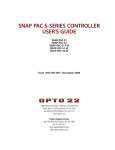
SNAP PAC S-SERIES CONTROLLER
USER’S GUIDE
Form 1592-070228—February 2007
43044 Business Park Drive • Temecula • CA 92590-3614
Phone: 800-321-OPTO (6786) or 951-695-3000
Fax: 800-832-OPTO (6786) or 951-695-2712
www.opto22.com
Product Support Services
800-TEK-OPTO (835-6786) or 951-695-3080
Fax: 951-695-3017
Email: [email protected]
Web: support.opto22.com
SNAP PAC S-Series User’s Guide
Form 1592-070228—February 2007
Copyright © 2005–2007 Opto 22.
All rights reserved.
Printed in the United States of America.
The information in this manual has been checked carefully and is believed to be accurate; however, Opto 22 assumes no
responsibility for possible inaccuracies or omissions. Specifications are subject to change without notice.
Opto 22 warrants all of its products to be free from defects in material or workmanship for 30 months from the
manufacturing date code. This warranty is limited to the original cost of the unit only and does not cover installation, labor, or
any other contingent costs. Opto 22 I/O modules and solid-state relays with date codes of 1/96 or later are guaranteed for life.
This lifetime warranty excludes reed relay, SNAP serial communication modules, SNAP PID modules, and modules that
contain mechanical contacts or switches. Opto 22 does not warrant any product, components, or parts not manufactured by
Opto 22; for these items, the warranty from the original manufacturer applies. These products include, but are not limited to,
OptoTerminal-G70, OptoTerminal-G75, and Sony Ericsson GT-48; see the product data sheet for specific warranty
information. Refer to Opto 22 form number 1042 for complete warranty information.
Cyrano, Opto 22 FactoryFloor, Optomux, and Pamux are registered trademarks of Opto 22. Generation 4, ioControl, ioDisplay,
ioManager, ioProject, ioUtilities, mistic, Nvio, Nvio.net Web Portal, OptoConnect, OptoControl, OptoDataLink, OptoDisplay,
OptoOPCServer, OptoScript, OptoServer, OptoTerminal, OptoUtilities, PAC Control, PAC Display, PAC Manager, PAC Project,
SNAP Ethernet I/O, SNAP I/O, SNAP OEM I/O, SNAP PAC System, SNAP Simple I/O, SNAP Ultimate I/O, and SNAP Wireless LAN
I/O are trademarks of Opto 22.
ActiveX, JScript, Microsoft, MS-DOS, VBScript, Visual Basic, Visual C++, and Windows are either registered trademarks or
trademarks of Microsoft Corporation in the United States and other countries. Linux is a registered trademark of Linus
Torvalds. Unicenter is a registered trademark of Computer Associates International, Inc. ARCNET is a registered trademark of
Datapoint Corporation. Modbus is a registered trademark of Schneider Electric. Wiegand is a registered trademark of Sensor
Engineering Corporation. Nokia, Nokia M2M Platform, Nokia M2M Gateway Software, and Nokia 31 GSM Connectivity
Terminal are trademarks or registered trademarks of Nokia Corporation. Sony is a trademark of Sony Corporation. Ericsson is a
trademark of Telefonaktiebolaget LM Ericsson.
All other brand or product names are trademarks or registered trademarks of their respective companies or organizations.
ii
SNAP PAC S-Series User’s Guide
Table of Contents
Chapter 1: Overview . . . . . . . . . . . . . . . . . . . . . . . . . . . . . . . . . . . . . . . . . . . . . . . . . . . . . 1
Introduction. . . . . . . . . . . . . . . . . . . . . . . . . . . . . . . . . . . . . . . . . . . . . . . . . . . . . . . . . . . . . . . . . . . . . . . . . . . . . . . . 1
Connectivity . . . . . . . . . . . . . . . . . . . . . . . . . . . . . . . . . . . . . . . . . . . . . . . . . . . . . . . . . . . . . . . . . . . . . . . . . . . 1
SNAP PAC S-Series Controller. . . . . . . . . . . . . . . . . . . . . . . . . . . . . . . . . . . . . . . . . . . . . . . . . . . . . . . . . . . . . . . . . 2
Serial Host Communication . . . . . . . . . . . . . . . . . . . . . . . . . . . . . . . . . . . . . . . . . . . . . . . . . . . . . . . . . . . . . . 2
Backward Compatibility . . . . . . . . . . . . . . . . . . . . . . . . . . . . . . . . . . . . . . . . . . . . . . . . . . . . . . . . . . . . . . . . . 2
Software. . . . . . . . . . . . . . . . . . . . . . . . . . . . . . . . . . . . . . . . . . . . . . . . . . . . . . . . . . . . . . . . . . . . . . . . . . . . . . . . . . . 2
Software Availability . . . . . . . . . . . . . . . . . . . . . . . . . . . . . . . . . . . . . . . . . . . . . . . . . . . . . . . . . . . . . . . . . . . . 3
Architectural Diagrams . . . . . . . . . . . . . . . . . . . . . . . . . . . . . . . . . . . . . . . . . . . . . . . . . . . . . . . . . . . . . . . . . . . . . . 4
Ethernet Connections to Host and I/O Units . . . . . . . . . . . . . . . . . . . . . . . . . . . . . . . . . . . . . . . . . . . . . . . . 4
Connections to Serial-based I/O Units . . . . . . . . . . . . . . . . . . . . . . . . . . . . . . . . . . . . . . . . . . . . . . . . . . . . . 6
Ethernet Link Redundancy . . . . . . . . . . . . . . . . . . . . . . . . . . . . . . . . . . . . . . . . . . . . . . . . . . . . . . . . . . . . . . . 7
Remote Host and I/O Unit Connections Using PPP . . . . . . . . . . . . . . . . . . . . . . . . . . . . . . . . . . . . . . . . . . 8
About This Guide . . . . . . . . . . . . . . . . . . . . . . . . . . . . . . . . . . . . . . . . . . . . . . . . . . . . . . . . . . . . . . . . . . . . . . . 9
Related Documentation . . . . . . . . . . . . . . . . . . . . . . . . . . . . . . . . . . . . . . . . . . . . . . . . . . . . . . . . . . . . . . . . . . . . . 9
For Help . . . . . . . . . . . . . . . . . . . . . . . . . . . . . . . . . . . . . . . . . . . . . . . . . . . . . . . . . . . . . . . . . . . . . . . . . . . . . . . . . . . 9
Chapter 2: Quick Start . . . . . . . . . . . . . . . . . . . . . . . . . . . . . . . . . . . . . . . . . . . . . . . . . .11
Installing and Configuring the Controller. . . . . . . . . . . . . . . . . . . . . . . . . . . . . . . . . . . . . . . . . . . . . . . . . . . . . 11
What You Will Need . . . . . . . . . . . . . . . . . . . . . . . . . . . . . . . . . . . . . . . . . . . . . . . . . . . . . . . . . . . . . . . . . . . 11
Installing Software . . . . . . . . . . . . . . . . . . . . . . . . . . . . . . . . . . . . . . . . . . . . . . . . . . . . . . . . . . . . . . . . . . . . . 11
Power Supply Recommendations . . . . . . . . . . . . . . . . . . . . . . . . . . . . . . . . . . . . . . . . . . . . . . . . . . . . . . . 12
Change to SNAP-PAC-S1 Power Input Range . . . . . . . . . . . . . . . . . . . . . . . . . . . . . . . . . . . . . . . . . . . . . 12
Installing Hardware . . . . . . . . . . . . . . . . . . . . . . . . . . . . . . . . . . . . . . . . . . . . . . . . . . . . . . . . . . . . . . . . . . . . 12
RS-232 and RS-485 Serial Networking . . . . . . . . . . . . . . . . . . . . . . . . . . . . . . . . . . . . . . . . . . . . . . . . . . . 13
RS-232 Connections . . . . . . . . . . . . . . . . . . . . . . . . . . . . . . . . . . . . . . . . . . . . . . . . . . . . . . . . . . . . . . . 13
Attaching the Modem to the Controller . . . . . . . . . . . . . . . . . . . . . . . . . . . . . . . . . . . . . . . . . . . . . . 14
SNAP PAC S-Series User’s Guide
iii
iii
RS-485 Connections . . . . . . . . . . . . . . . . . . . . . . . . . . . . . . . . . . . . . . . . . . . . . . . . . . . . . . . . . . . . . . .14
Wiring the 10-pin Serial Connector . . . . . . . . . . . . . . . . . . . . . . . . . . . . . . . . . . . . . . . . . . . . . . . . . .15
Assigning an IP Address . . . . . . . . . . . . . . . . . . . . . . . . . . . . . . . . . . . . . . . . . . . . . . . . . . . . . . . . . . . . . . . .16
Mounting the Controller . . . . . . . . . . . . . . . . . . . . . . . . . . . . . . . . . . . . . . . . . . . . . . . . . . . . . . . . . . . . . . . .16
Panel Mounting and Dimensions . . . . . . . . . . . . . . . . . . . . . . . . . . . . . . . . . . . . . . . . . . . . . . . . . . . .17
DIN-Rail Mounting and Dimensions . . . . . . . . . . . . . . . . . . . . . . . . . . . . . . . . . . . . . . . . . . . . . . . . .18
About the Controller’s Memory Map . . . . . . . . . . . . . . . . . . . . . . . . . . . . . . . . . . . . . . . . . . . . . . . . . . . . . . . . . 19
Using Data for Peer-to-Peer Communication . . . . . . . . . . . . . . . . . . . . . . . . . . . . . . . . . . . . . . . . . . . . . .19
What’s Next? . . . . . . . . . . . . . . . . . . . . . . . . . . . . . . . . . . . . . . . . . . . . . . . . . . . . . . . . . . . . . . . . . . . . . . . . . . . . . 19
Chapter 3: Maintenance and Troubleshooting . . . . . . . . . . . . . . . . . . . . . . . . . . . 21
Troubleshooting . . . . . . . . . . . . . . . . . . . . . . . . . . . . . . . . . . . . . . . . . . . . . . . . . . . . . . . . . . . . . . . . . . . . . . . . . . 21
Checking Power . . . . . . . . . . . . . . . . . . . . . . . . . . . . . . . . . . . . . . . . . . . . . . . . . . . . . . . . . . . . . . . . . . . . . . .21
Communicating on an Ethernet Network . . . . . . . . . . . . . . . . . . . . . . . . . . . . . . . . . . . . . . . . . . . . . . . . .22
Pinging the Controller . . . . . . . . . . . . . . . . . . . . . . . . . . . . . . . . . . . . . . . . . . . . . . . . . . . . . . . . . . . . . .22
Solving Network Problems . . . . . . . . . . . . . . . . . . . . . . . . . . . . . . . . . . . . . . . . . . . . . . . . . . . . . . . . . . . . . .23
Create a Network Diagram . . . . . . . . . . . . . . . . . . . . . . . . . . . . . . . . . . . . . . . . . . . . . . . . . . . . . . . . . .23
Check Ethernet Errors . . . . . . . . . . . . . . . . . . . . . . . . . . . . . . . . . . . . . . . . . . . . . . . . . . . . . . . . . . . . . .23
Analyze Communication Packets . . . . . . . . . . . . . . . . . . . . . . . . . . . . . . . . . . . . . . . . . . . . . . . . . . . .24
Have Your Network Certified . . . . . . . . . . . . . . . . . . . . . . . . . . . . . . . . . . . . . . . . . . . . . . . . . . . . . . . .24
TCP Settings . . . . . . . . . . . . . . . . . . . . . . . . . . . . . . . . . . . . . . . . . . . . . . . . . . . . . . . . . . . . . . . . . . . . . . . . . . .24
Communicating on a Serial Network . . . . . . . . . . . . . . . . . . . . . . . . . . . . . . . . . . . . . . . . . . . . . . . . . . . . .26
Maintaining the Controller . . . . . . . . . . . . . . . . . . . . . . . . . . . . . . . . . . . . . . . . . . . . . . . . . . . . . . . . . . . . . . . . . 26
Getting Device and Firmware Information . . . . . . . . . . . . . . . . . . . . . . . . . . . . . . . . . . . . . . . . . . . . . . . .26
Changing the Controller’s IP Address . . . . . . . . . . . . . . . . . . . . . . . . . . . . . . . . . . . . . . . . . . . . . . . . . . . . .27
Resetting the Controller . . . . . . . . . . . . . . . . . . . . . . . . . . . . . . . . . . . . . . . . . . . . . . . . . . . . . . . . . . . . . . . .28
Loading New Firmware . . . . . . . . . . . . . . . . . . . . . . . . . . . . . . . . . . . . . . . . . . . . . . . . . . . . . . . . . . . . . . . . .28
Setting Time and Date . . . . . . . . . . . . . . . . . . . . . . . . . . . . . . . . . . . . . . . . . . . . . . . . . . . . . . . . . . . . . . . . . .29
SNAP-PAC-S1 Controller STAT LED Blink Codes . . . . . . . . . . . . . . . . . . . . . . . . . . . . . . . . . . . . . . . . . . . .29
SNAP-PAC-S1 Controller Serial Port LEDs . . . . . . . . . . . . . . . . . . . . . . . . . . . . . . . . . . . . . . . . . . . . . . . . .30
Appendix A: Technical Specifications . . . . . . . . . . . . . . . . . . . . . . . . . . . . . . . . . . . 31
SNAP-PAC-S1 Specifications. . . . . . . . . . . . . . . . . . . . . . . . . . . . . . . . . . . . . . . . . . . . . . . . . . . . . . . . . . . . . . . . 31
Connectors, Indicators, and Pinouts. . . . . . . . . . . . . . . . . . . . . . . . . . . . . . . . . . . . . . . . . . . . . . . . . . . . . . . . . . 32
Dimensions. . . . . . . . . . . . . . . . . . . . . . . . . . . . . . . . . . . . . . . . . . . . . . . . . . . . . . . . . . . . . . . . . . . . . . . . . . . . . . . 33
Appendix B: PPP Support in Microsoft Windows . . . . . . . . . . . . . . . . . . . . . . . . 35
iv
SNAP PAC S-Series User’s Guide
Configuring PPP Support in Microsoft Windows . . . . . . . . . . . . . . . . . . . . . . . . . . . . . . . . . . . . . . . . . . . . . . 35
Configuring Microsoft Windows Dial-up Networking on Windows 95/98 . . . . . . . . . . . . . . . . . . . . . 35
Configuring Microsoft Windows Dial-up Networking on Windows NT . . . . . . . . . . . . . . . . . . . . . . . . 36
Configuring Microsoft Windows Dial-up Networking on Windows 2000 . . . . . . . . . . . . . . . . . . . . . 37
Configuring Microsoft Windows Dial-up Networking on Windows ME . . . . . . . . . . . . . . . . . . . . . . . 40
Setting Up a Remote Access Server on the PC (Windows 2000 Advanced Server) . . . . . . . . . . . . . . 46
Setting Up a Remote Access Server on the PC (Windows NT) . . . . . . . . . . . . . . . . . . . . . . . . . . . . . . . 49
SNAP PAC S-Series User’s Guide
vv
vi
SNAP PAC S-Series User’s Guide
Chapter 1
Overview
Introduction
SNAP PAC S-series programmable
automation controllers provide
powerful, real-time control and
communication to meet your industrial
control, monitoring, and data
acquisition needs. As part of an Opto 22
input/output (I/O) system, one of these
compact, industrially hardened
controllers can handle multiple control,
automation, and data acquisition tasks
involving digital and analog control,
serial string handling, PID, and
enterprise connectivity.
SNAP-PAC-S1
controller
Connecting to Opto 22 serial- and
Ethernet-based I/O systems, a SNAP
PAC S-series controller runs control
programs written in Opto 22’s PAC Control™ software to monitor and control a wide range of
devices and equipment. SNAP PAC S-series controllers are well-suited to original equipment
manufacturers (OEMs), system integrators, and end-users in process control, discrete manufacturing,
or hybrid industries and applications.
Connectivity
SNAP PAC S-series controllers communicate over standard 10/100 Mbps Ethernet networks and can
be attached to existing wired or wireless Ethernet networks. The controllers can also be used in an
independent control network built with standard, off-the-shelf Ethernet hardware.
SNAP PAC S-series controllers provide multiple serial interfaces for PPP-based host and serial I/O
system communication. Two RS-232 serial links (one with and one without handshaking) support
remote serial device communication as well as Point-to-Point Protocol (PPP) modem connections
for creating TCP/IP networks over serial or PSTN (Public Switched Telephone Network) lines. An
SNAP PAC S-Series User’s Guide
11
SNAP PAC S-SERIES CONTROLLER
RS-485 serial interface connects to legacy Opto 22 mistic™ I/O units, including the serial B3000 brain
and remote mistic bricks.
SNAP PAC S-Series Controller
The first controller in the SNAP PAC S-series is the SNAP-PAC-S1. This controller includes two
independent 10/100 Mbps Ethernet interfaces for networking through an Ethernet switch to
Ethernet hosts and to SNAP Simple and SNAP Ethernet I/O™ units, which provide the connections to
digital and analog sensors and actuators as well as serial devices. These independent Ethernet
interfaces have separate IP addresses that can be used with PAC Project™ Professional software to
set up redundant network links to safeguard the availability and reliability of an I/O system, or to
segment a control system’s network from the enterprise LAN.
The SNAP-PAC-S1 simultaneously runs up to 32 PAC Control flowcharts, although the PAC Control
strategy can actually contain a much larger number of flowcharts. The total number of flowcharts is
limited only by the controller memory available for strategy storage.
Serial Host Communication
Two RS-232 serial interfaces are available on SNAP PAC S-series controllers. One port supports a
modem connection using PPP, while both support general-purpose communication with serial
devices. You can send and receive data from one or two serial devices connected directly to the
controller. For additional serial host interfaces, you can add one or more SNAP serial communication
modules on attached SNAP Ethernet-based I/O units.
Backward Compatibility
The SNAP-PAC-S1 controller also has an RS-485 serial interface for connecting to Opto 22 mistic I/O
units. This enables you to use PAC Control Professional’s ability to import control programs (or
strategies) written in OptoControl™ software to integrate older Opto 22 I/O systems into modern
control hardware running on Ethernet networks. For detailed information on updating control
strategies and integrating legacy control hardware into modern systems, see the FactoryFloor to PAC
Project Migration Technical Note (Opto 22 form 1692).
Software
SNAP PAC controllers use Opto 22’s PAC Project Microsoft® Windows®-compatible automation
software for programming, human-machine-interface (HMI) development, and OPC connectivity.
Two versions of PAC Project are available:
•
2
PAC Project Basic includes PAC Control for developing control programs, PAC Display™ for
creating operator interfaces, and PAC Manager™ configuration software.
SNAP PAC S-Series User’s Guide
CHAPTER 1: OVERVIEW
•
PAC Project Professional adds expanded versions of PAC Control and PAC Display plus
OptoOPCServer™ software for exchanging data with OPC 2.0-compliant client software
applications.
The PAC Project software suite includes the following applications:
•
PAC Control Basic is a graphical, flowchart-based programming tool for machine control and
process applications. Using PAC Control, you create, download, and run strategies on a SNAP
PAC controller. In addition to flowchart programming with subroutine capability, PAC Control
includes a powerful, built-in scripting language based on C and other procedural languages.
PAC Control Professional adds the capability of importing OptoControl strategies, support for
mistic I/O units, and using a SNAP PAC controller’s independent Ethernet interfaces to segment
networks.
•
PAC Display Basic is an intuitive HMI package for building operator interfaces, or projects, for
communicating with a SNAP PAC controller. PAC Display offers a full-featured HMI including
alarming, trending, and a built-in library of 3,000 industrial automation graphics. PAC Display
Professional adds the capability of importing projects created in OptoDisplay and using
redundant Ethernet links on SNAP PAC controllers. PAC Display Professional can also connect to
Ethernet-based FactoryFloor controllers running OptoControl strategies.
•
OptoOPCServer™ (PAC Project Professional only) is a fast, efficient OPC 2.0-compliant server
for communicating with many Opto 22 products, including:
– SNAP PAC S-series controllers and other SNAP controller/brains running PAC Control
strategies
– SNAP Ethernet-based I/O units that use SNAP brains like the SNAP-B3000-ENET or
SNAP-ENET-M64
– Ethernet-based FactoryFloor controllers running OptoControl strategies
Using OptoOPCServer, you can consolidate data from all these Opto 22 systems into the OPC
client software of your choice, such as third-party HMI and data acquisition packages, and
custom software applications you create with tools such as Visual C++®.
•
OptoDataLink™ (PAC Project Professional only) is an easy-to-use database connectivity tool
that establishes links between Opto 22 controllers and various databases, including Microsoft
SQL Server®, Microsoft Access, and others.
•
PAC Manager™ is a utility application for assigning IP addresses to SNAP PAC controllers,
reading or changing basic controller configuration, downloading firmware upgrades, and more.
PAC Manager is also used to configure the I/O units that communicate with the controller.
Software Availability
PAC Project Basic is included with SNAP PAC controllers and is a free download from the Opto 22
Web site. PAC Project Professional is available for purchase on a CD with both Acrobat PDF format
and printed documentation. To get PAC Project Professional immediately, you can buy and
download the software from the Opto 22 Web site at www.opto22.com; the CD and printed
documentation will be shipped to you. You can also separately purchase PAC Control Professional,
SNAP PAC S-Series User’s Guide
33
ARCHITECTURAL DIAGRAMS
PAC Display Professional, OptoOPCServer, and OptoDataLink as needed. For additional information,
see the PAC Project data sheet, Opto 22 form #1699.
Architectural Diagrams
Because SNAP PAC S-series controllers have multiple Ethernet and serial interfaces, these controllers
are suitable for use in a variety of system layouts and architectures. Dual independent Ethernet
interfaces, for example, let you configure a network for link redundancy or segmented networking. A
PPP serial interface provides a dial-up modem link for remotely located control systems, while
two-wire RS-485 support integrates existing Opto 22 mistic serial-based I/O units into contemporary
Ethernet-based systems.
Ethernet Connections to Host and I/O Units
The following diagram shows multiple Ethernet-based Opto 22 I/O units connected together over
an Ethernet network and controlled by a SNAP PAC S-series controller running a control strategy. The
controller is also connected to a larger, separate enterprise Ethernet network to provide data to two
PCs running Opto 22’s PAC Display HMI software and OptoOPCServer. Sitting between the two
networks, the SNAP PAC S-series controller segments enterprise traffic from the control network.
4
SNAP PAC S-Series User’s Guide
CHAPTER 1: OVERVIEW
Enterprise Network
PC running PAC
Display Professional
PC running
OptoOPCServer
ENET 2
ENET 1
SNAP- PAC- S1
SNAP PAC S-series controller communicates
with host computers through one network
interface and controls I/O with other devices
through the other interface.
SNAP PAC
Ethernet switch,
network #1
Control Network
Ethernet switch,
network #2
I/O units are controlled by the
controller on an isolated network.
Sensors and actuators,
location #1
Sensors and actuators,
location #2
SNAP PAC S-Series User’s Guide
55
ARCHITECTURAL DIAGRAMS
Connections to Serial-based I/O Units
In the following diagram, a SNAP PAC S-series controller is connected to multiple Opto 22
serial-based I/O units over an RS-485 serial network. The controller is also connected to a larger,
separate enterprise Ethernet network to provide process data to a PC running Opto 22’s PAC Display
HMI software.
PC running PAC
Display Professional
PC running PAC
Control Professional
ENET 2
ENET 1
SNAP- PAC- S1
SNAP PAC
Ethernet
switch
RS-485 serial
network
Sensors and actuators,
location #1
SNAP PAC S-series controller
controls all I/O units.
I/O units are connected via a 2-wire RS-485 serial
network and are controlled by the SNAP PAC
S-series controller. Each I/O unit is connected to its
own group of sensors and actuators.
Sensors and actuators,
location #2
Sensors and actuators,
location #3
The diagram also shows a PC running PAC Control Professional, an application for developing control
programs (or strategies) to run on the SNAP controller. Once developed, the strategy is downloaded
to the controller and runs independently.
6
SNAP PAC S-Series User’s Guide
CHAPTER 1: OVERVIEW
Ethernet Link Redundancy
The following diagram shows a SNAP PAC S-series controller connected to two separate Ethernet
network links. This configuration addresses the concern that an Ethernet network may fail or need
maintenance, leaving the PC running OptoOPCServer, the PC running PAC Display, the controller, and
the I/O units unable to communicate. In this configuration, if one link goes down, devices can still
communicate on the other. Each PC has two network interface cards (NICs), and the SNAP PAC
S-series controller and the I/O units (SNAP-PAC-EB1 and -EB2 brains) have two network interfaces as
well.
Opto 22 Redundant Network
PC with two
NICs running
PAC Display
PC with two
NICs running
OptoOPCServer
ENET 2
Ethernet switch,
network #2
EN ET 1
SNAP- PAC- S1
SNAP PAC
Ethernet switch,
network #1
SNAP PAC S-series controller
controls all I/O units.
I/O units are all connected by the controller. Each I/O unit
is connected to its own group of sensors and actuators,
but all are connected to the same two networks.
SNAP PAC
brains
ETHERNET 0
A
C
T
L
N
K
STAT
SNAP PAC
brains
232
485
Tx
Rx
C
RTS
CTS
C
ETHERNET 0
A
C
T
L
N
K
232
485
Tx
Rx
C
RTS
CTS
C
T1
T2
A
C
T
STAT
T1
T2
BIAS
A
C
T
L
N
K
BIAS
L
N
K
ETHERNET 1
ETHERNET 1
Sensors and actuators,
location #1
Sensors and actuators,
location #2
SNAP PAC S-Series User’s Guide
77
ARCHITECTURAL DIAGRAMS
Remote Host and I/O Unit Connections Using PPP
For remote monitoring and control, you can use a SNAP PAC S-series controller to connect to a
remote host such as a PC or to a SNAP Ethernet-based I/O unit using a dial-up link. For this use, the
controller communicates using the Point-to-Point Protocol (PPP) over a modem.
Enterprise Network
PC running PAC
Display Professional
PC running
OptoOPCServer
ENET 2
ENET 1
SNAP- PAC- S1
SNAP PAC S-series controller uses
a PPP dial-up telephone
connection to communicate with
I/O units at a remote location.
SNAP PAC
Ethernet switch
Dial-up
modem
Dial-up modem at
remote location
SNAP I/O unit at remote
location is connected to
sensors and actuators.
Sensors and actuators
at remote location
8
SNAP PAC S-Series User’s Guide
CHAPTER 1: OVERVIEW
About This Guide
See the following sections for basic information on setting up and maintaining a SNAP PAC S-series
controller.
•
Chapter 2, “Quick Start”
•
Chapter 3, “Maintenance and Troubleshooting”
•
Appendix A, “Technical Specifications”
Related Documentation
You may also need the following documentation, depending on your application:
To use this
See this
Opto 22
form #
SNAP PAC S-series
controller and Opto 22
I/O units
PAC Manager User’s Guide
1704
SNAP Ultimate I/O
SNAP Ethernet I/O
SNAP Simple I/O
SNAP Ethernet-Based I/O Units User’s Guide
OptoMMP Protocol Guide
1460
1465
PAC Control strategies
PAC Control User’s Guide
PAC Control Command Reference
PAC Control Commands Quick Reference Card
1700
1701
1703
All of this documentation is on the CD that came with the controller; all forms are available on our
Web site (www.opto22.com) for downloading. The easiest way to find one is to search on the form
number.
For Help
If you have problems installing or using a SNAP PAC S-series controller and cannot find the help you
need in this guide, contact Opto 22 Product Support.
Phone:
800-TEK-OPTO (835-6786)
951-695-3080
(Hours are Monday through Friday,
7 a.m. to 5 p.m. Pacific Time)
Fax:
951-695-3017
Email:
[email protected]
Opto 22 website:
www.opto22.com
NOTE: Email messages and
phone calls to Opto 22
Product Support are
grouped together and
answered in the order
received.
SNAP PAC S-Series User’s Guide
99
FOR HELP
When calling for technical support, be prepared to provide the following information about your
system to the Product Support engineer:
•
Software and version being used
•
Controller firmware version
•
PC configuration
•
A complete description of your hardware and operating systems, including:
– switch configuration
– type of power supply
– types of I/O units installed
– third-party devices installed (for example, barcode readers)
•
10
Specific error messages seen.
SNAP PAC S-Series User’s Guide
Chapter 2
Quick Start
Installing and Configuring the Controller
What You Will Need
•
PC running Microsoft Windows 2000 or Windows XP workstation operating system, with a
10/100 MB Ethernet interface, the TCP/IP protocol installed, and a valid IP address, on the same
subnet as the controller
•
Crossover cable (for direct connection to the PC) or an available connection to a standard
10BASE-T or 100BASE-TX Ethernet network
•
SNAP PAC S-series controller
•
CD that came with the controller or PAC Project Professional CD (purchased separately)
•
8–32 VDC power supply (see “Power Supply Recommendations” on page 12 for specific
information and recommendations)
•
Small flathead screwdriver
•
One or both of the following, depending on your I/O system requirements:
– Opto 22 SNAP PAC Ethernet brain-based I/O units on the same Ethernet network as the
controller.
– Opto 22 legacy SNAP Ethernet-based I/O units—SNAP Simple I/O, SNAP Ethernet I/O, or
SNAP Ultimate I/O units—on the same Ethernet network as the controller.
– Opto 22 RS-485 serial-based I/O units—serial B3000, SNAP-BRS, B100/B200 brains, or
mistic remote bricks (G4D16R, G4D32RS, G4A8R)—on a two-wire RS-485 network.
Installing Software
In your CD-ROM drive, insert the CD that came with the SNAP PAC S-series controller. The installation
wizard should start automatically. If it doesn’t, use Windows Explorer to navigate to your CD-ROM
drive and then double-click setup.exe.
SNAP PAC S-Series User’s Guide
11
11
INSTALLING AND CONFIGURING THE CONTROLLER
Power Supply Recommendations
Opto 22 recommends that the SNAP PAC S-series controller be powered with an Opto 22 SNAP-PS24
or SNAP-PS24U power supply. In place of one of these power supplies, Opto 22 recommends an
8-32 VDC linear supply with adequate current ratings for the load. For more information on power
requirements, see “SNAP-PAC-S1 Specifications” on page 31.
Change to SNAP-PAC-S1 Power Input Range
Current SNAP-PAC-S1 controllers have an 8–32 VDC input range, but earlier SNAP-PAC-S1 controllers
use an 8–24 VDC input range. Before applying power to the controller, confirm that the
input voltage is within the voltage range shown on the faceplate.
The voltage input rating can also be determined based on the SNAP-PAC-S1’s serial number as
follows:
•
SNAP-PAC-S1 controllers with serial number 500000 and higher have an 8–32 VDC voltage input
rating.
•
SNAP-PAC-S1 controllers with serial numbers lower than 500000 have an 8–24 VDC input
rating. Using an input voltage above this range will cause damage that is not covered
by the warranty.
The SNAP-PAC-S1 serial number appears on the sticker on the side of the unit. The input voltage
rating is shown on the top cover of the controller.
IP Address
IP Address
MAC 1: 00-A0-3D-00-XX-XX
MAC 1: 00-A0-3D-00-XX-XX
CC
501023
SNAP-PAC-S1
input voltage
rating
SNAP-PAC-S1
serial number
Installing Hardware
1. Install Opto 22 I/O units according to instructions in form #1460, the SNAP Ethernet-Based I/O
Units User’s Guide.
This guide is on the CD that was shipped with the I/O unit’s brain; it is also available from our
website at www.opto22.com.
2. Choose a convenient mounting location for the SNAP PAC S-series controller and either
panel-mount or DIN-rail mount it according to the diagrams on page 17 and page 18.
3. Confirm that the power supply to be used with the controller is turned off or unplugged, and
discharge any residual charge that may remain in the power supply.
4. With the power supply off or unplugged, connect the power supply to the controller.
12
SNAP PAC S-Series User’s Guide
CHAPTER 2: QUICK START
CAUTION: Reversing wire polarity may cause damage to your controller. This damage is not covered
by Opto 22’s warranty. If you are not certain about the polarity of the wires on your power supply,
check with a meter.
a. With the power supply off or unplugged, connect the + (positive) lead from the power
supply (normally red) to the + (positive) terminal on the face of the controller.
b. Connect the COM wire from the power supply (normally black) to the – (negative) terminal
on the face of the controller.
c. Connect a lead from a known earth/chassis ground to the (ground) terminal on the face
of the controller.
IMPORTANT: Do not yet turn on power to the controller.
5. Using Category 5 or superior solid unshielded twisted-pair cable, connect the SNAP PAC
S-series controller using Ethernet port ENET 1 in one of the following ways:
– (Recommended for initial configuration) Connect to a PC directly, using an Ethernet
crossover cable.
– Connect to a standard 10BASE-T or 100BASE-TX Ethernet network that has a PC on the
same subnet as the controller and does NOT have a Dynamic Host Configuration Protocol
(DHCP) server.
Maximum cable or segment length is 100 meters; minimum cable length is one meter.
6. If the controller will connect to I/O units on an RS-485 serial network, connect the serial cable
following the instructions in “RS-232 and RS-485 Serial Networking” on page 13.
IMPORTANT: Do not yet turn on power to the controller.
7. Before turning on power to the controller, follow steps in Opto 22 form #1704, the PAC
Manager User’s Guide, to assign the controller an IP address.
This guide is in Adobe Acrobat PDF format on the CD that came with the controller and is also
available from our Web site, www.opto22.com. Note that you can use PAC Manager to assign IP
addresses to the controller and I/O units at the same time.
RS-232 and RS-485 Serial Networking
SNAP PAC S-series controllers provide both RS-232 and RS-485 serial communication interfaces.
Serial communication ports and their corresponding wiring pinouts are shown in “Connectors,
Indicators, and Pinouts” on page 32.
RS-232 Connections
You can use the RS-232 ports on a SNAP PAC S-series controller to:
•
Direct connect to a device that supports RS-232 communication.
•
Connect to a modem and make a serial Point-to-Point Protocol (PPP) connection to a remote
PC or other device that supports PPP.
SNAP PAC S-Series User’s Guide
13
13
INSTALLING AND CONFIGURING THE CONTROLLER
To configure RS-232 serial communication ports on a SNAP PAC S-series controller, see the
instructions in the PAC Manager User’s Guide. The controller cannot make a direct RS-232 serial
connection with an Opto 22 I/O unit; however, it is possible to connect to an Opto 22 I/O unit that
supports PPP communications.
Attaching the Modem to the Controller
To work properly with the SNAP PAC S-series controller, a modem must be able to store settings in
non-volatile RAM (NVRAM) and default to those settings on reset.
IMPORTANT: Any modem used with the controller must implement the Carrier Detect (CD) signal or use
a custom cable that connects CD to Data Terminal Ready (DTR).
1. Connect the modem to the controller using a modem cable with female DB-9 connector. If
necessary, see “Connectors, Indicators, and Pinouts” on page 32 for pinout details.
2. Store configuration settings to the modem’s NVRAM, following instructions in the user’s guide
for your modem.
NOTE: Configuration settings must be stored to the modem’s NVRAM so they will be loaded when the
controller sends a reset command to the modem.
3. If PCs will dial up the controller, set up Windows dial-up networking on the PCs that will call the
controller. See the section for your operating system in Appendix B, “PPP Support in Microsoft
Windows.”
4. If you want the controller to dial up a PC, set up a remote access server (RAS) on the PC. This is
also described in Appendix B, “PPP Support in Microsoft Windows.”
RS-485 Connections
You can use an RS-485 serial port on a SNAP PAC S-series controller to connect to Opto 22 I/O units
on a two-wire, RS-485 serial network. These I/O units include serial B3000 brains and mistic remote
bricks such as the G4D16R, G4D32RS, and the G4A8R.
NOTE: The controller’s RS-485 interface does not currently support mistic signal interrupts.
14
SNAP PAC S-Series User’s Guide
CHAPTER 2: QUICK START
RS-485 bias and termination settings are
configured using two DIP switches located on
the top of the SNAP PAC S-series controller.
Bias—. Only one device on an RS-485 network
should have bias turned on. If there are no other
devices with bias active, you can set the SNAP
PAC S-series controller to do so.
Termination—. Termination settings depend
on the controller’s location on the RS-485
network. Settings for different controller
locations are shown in the table below.
SNAP PAC S-series controller
location on RS-485 network
Switch
Position
Description
ON
Bias: active
OFF
Bias: inactive
ON
Termination: active
OFF
Termination: inactive
1
2
DIP switches
RS-485
termination
(Portion of top view)
Termination
Active
At the End
In the Middle
(floating)
Termination
Inactive
Wiring the 10-pin Serial Connector
Serial ports 1 and 2 share a 10-pin pluggable connector (Phoenix Contact, part number
FK-MC 0.5 - 2.5, supplied with the controller). When inserting and removing wire leads into this
connector, do the following:
1. Completely depress the small orange tab for the
Hole
appropriate opening with a small screwdriver.
2. While holding the tab down with the
screwdriver, insert or remove the wire as needed. Orange
tab
3. Release the orange tab.
SNAP PAC S-Series User’s Guide
15
15
INSTALLING AND CONFIGURING THE CONTROLLER
Assigning an IP Address
See instructions in Opto 22 form #1704, the PAC Manager User’s Guide, to assign an IP address to the
SNAP PAC S-series controller.
SNAP PAC controllers have two independent Ethernet network interfaces, labeled on the top of the
controller as ENET1 and ENET2. By assigning a different IP address to each interface you can connect
the controller to two different Ethernet networks. PAC Control Professional provides commands to
configure the IP addresses.
Mounting the Controller
The SNAP PAC S-series controller can be panel mounted or mounted on a DIN rail. DIN-rail mounting
requires an adapter clip, part number SNAP-PSDIN (not included). The controller is the same size and
shape as most SNAP power supplies.
16
SNAP PAC S-Series User’s Guide
CHAPTER 2: QUICK START
Panel Mounting and Dimensions
Use two screws on each side of the SNAP PAC S-series
controller to mount it to a panel.
SNAP PAC S-Series User’s Guide
17
17
INSTALLING AND CONFIGURING THE CONTROLLER
DIN-Rail Mounting and Dimensions
DIN-rail mounting requires an adapter clip, part number
SNAP-PSDIN (not included).
For DIN-rail mounting, remove the four screws that fasten
the panel mounting base plate to the controller. Save
screws. Remove the base plate.
Use the four screws to fasten the DIN-rail adapter clip to
the bottom of the controller, as shown.
Optional DIN-rail
adapter clip
18
SNAP PAC S-Series User’s Guide
CHAPTER 2: QUICK START
About the Controller’s Memory Map
Like SNAP Ethernet-based brains, a SNAP PAC S-series controller uses a memory mapped system for
storing data and making that data available to other devices on the Ethernet network. This data
includes configuration data, status information about the controller itself, and PAC Control strategy
variable data that may be needed by a peer on the network.
Although SNAP PAC S-series controllers are designed to run PAC Control strategies, you can also
write your own software applications to communicate with the controller’s memory map, either
instead of or in addition to using PAC Control. You can use the OptoMMP Communication Toolkit or
the IEEE 1394-based protocol for writing your applications. Both are explained in Opto 22 form
#1465, the OptoMMP Protocol Guide, which also includes complete details of the memory map.
Although this guide is written for I/O units, you can use the same information for a SNAP PAC
S-series controller. Just be aware that many sections do not apply, since the controller’s memory
map doesn’t include any I/O point or related information.
The SNAP PAC S-series controller’s memory map includes only the following areas:
Status Area Read
Communications Port Configuration
Date and Time Configuration
Status Area Write
Security Configuration
PPP Configuration
PPP Status
Scratch Pad
Using Data for Peer-to-Peer Communication
Scratch Pad areas within the SNAP PAC S-series controller’s memory map provide a way for other
devices on the Ethernet network to access data in the controller. For descriptions of the Scratch Pad
areas—bits, integers, floats, and strings—see the PAC Manager User’s Guide. For help in using PAC
Control commands to access Scratch Pad areas, see “I/O Unit—Scratch Pad Commands” in Chapter
10 of the PAC Control User’s Guide.
If you are not using PAC Control but writing your own software applications to access the Scratch Pad
areas, see the OptoMMP Protocol Guide. This guide is written for I/O units, but much of the same
information on programming applies to SNAP PAC S-series and other Ethernet-based Opto 22
controllers. The Scratch Pad areas of the memory map are described in the programming guide’s
appendix; the SNAP PAC S-series controller’s Scratch Pad areas are identical to the SNAP Ultimate
brain’s.
What’s Next?
Your controller is now ready for use.
•
To create PAC Control strategies to run on the controller, see the PAC Control User’s Guide and the
PAC Control Command Reference. Both are available in PDF format on the CD that came with the
controller.
SNAP PAC S-Series User’s Guide
19
19
WHAT’S NEXT?
•
To work with the following items on the controller, see instructions in the PAC Manager User’s
Guide:
– File system and FTP
– Security settings
– Port configuration
20
SNAP PAC S-Series User’s Guide
Chapter 3
Maintenance and
Troubleshooting
•
To troubleshoot problems that may have occurred, see the section “Troubleshooting”
starting below.
•
For maintenance information about the SNAP PAC S-series controller, see the section
“Maintaining the Controller” on page 26.
Troubleshooting
If you encounter a problem while installing or using the SNAP PAC S-series controller, check the
information in this section. If you need to contact Opto 22 Product Support, see “For Help” on
page 9.
Checking Power
When troubleshooting any problem with your controller, first check that the required power is
correctly supplied.
IMPORTANT: The SNAP PAC S-series standalone controller requires 8–32 VDC power, not the 5 VDC
power used by previous SNAP controllers and controller/brains. If you are replacing an older SNAP
controller or controller/brain with a SNAP PAC S-series controller, make sure that 8–32 VDC power is
supplied.
1. Review the information in “Power Supply Recommendations” on page 12 and the power
requirements listed in “SNAP-PAC-S1 Specifications” on page 31. Confirm that the power supply
used with the SNAP PAC S-series controller meets these requirements.
2. Confirm that all leads connected to the controller and the power supply are securely attached.
These connections are described in “Installing Hardware” on page 12.
3. Verify that the controller’s ground terminal is connected to a known earth/chassis ground as
described in “Installing Hardware” on page 12.
4. Confirm that two Phillips-head screws are installed on the wide sides of the case, one screw per
side. (These screws secure and ground the controller’s internal components.)
SNAP PAC S-Series User’s Guide
21
21
TROUBLESHOOTING
Communicating on an Ethernet Network
If you attempt to connect to the controller using its IP address and you cannot, first check the
following:
•
Make sure the controller has been turned on, the STAT LED is lit and not blinking, and the LNK
and LEDs for the connected Ethernet interfaces are lit. (See “Connectors, Indicators, and
Pinouts” on page 32.)
•
Verify that you typed in the correct address for the controller. Check the label on the side of the
controller, where the IP address should be written.
•
Make sure the controller has been assigned a valid IP address and subnet mask. SNAP PAC
S-series controllers come from the factory with a default IP address of 0.0.0.0, which is invalid.
The default subnet mask is 255.255.255.0. To assign IP address and subnet mask, see the PAC
Manager User’s Guide.
•
Make sure you have up-to-date drivers installed on your computer’s Network Interface Card
(NIC). Contact your system administrator or the manufacturer of the card for help.
•
Make sure any firewall in the computer (such as the built-in firewall in Windows XP) is
temporarily disabled before you try to assign or change IP addresses, load firmware using PAC
Manager’s Maintenance window, or work with files on the controller. BootP and FTP cannot
function through a firewall in the PC. Firewalls in a router are less likely to be a problem unless
certain ports (such as FTP client) have been blocked, either by default or on purpose.
Pinging the Controller
If you still cannot communicate with the controller after you have checked these items, try to reach it
using the PING application.
1. Choose Start➞Run and type cmd to open a command prompt.
2. At the prompt, type: ping [controller’s IP address]
For example, type:
ping 10.192.54.40
At this point be sure to check for other devices on the Ethernet network that may have the
same IP address.
If the controller responds, go to “Maintaining the Controller” on page 26.
If the PING command cannot be found, choose Start➞Control Panel➞Network. Make sure
TCP/IP is configured as a protocol and that an IP address and subnet mask are assigned.
If you see the message “Destination host route not defined,” the controller probably has an
inappropriate IP address and subnet mask. Make sure the IP address and subnet mask on the
controller are compatible with those on the computer. Follow directions in the PAC Manager User’s
Guide to check the IP address and subnet mask on the controller and change them if necessary.
If you see the message “No response from host,” check the following:
22
•
Are the computer and controller correctly connected? Is the controller turned on?
•
Are the IP address and subnet mask on the controller compatible with those on the computer?
SNAP PAC S-Series User’s Guide
CHAPTER 3: MAINTENANCE AND TROUBLESHOOTING
•
Is the controller in bootloader mode? (If the reset button is held down for too long, the
controller will enter bootloader mode, which is indicated by the STAT LED blinking seven times
quickly.)
If you still cannot ping the controller, contact Opto 22 Product Support. (See “For Help” on
page 9 for contact information.)
Solving Network Problems
If there are recurring problems in communicating with the controller, check your network. The wires,
switches, and other parts in your Ethernet network are not part of the Opto 22 hardware, but any
problems in your network may affect communication with Opto 22 products.
Create a Network Diagram
First, create a network diagram and verify the following:
•
Cable connectors are firmly inserted.
•
The switch has power. Switch LEDs indicate that the connection is up.
•
Neither the PC nor the controller unit uses the switch’s uplink port.
•
The controller’s LNK LED is lit.
Check Ethernet Errors
Next, use PAC Manager to check any Ethernet errors reported. These errors indicate network
problems. You will need to know the controller’s IP address.
1. Choose Start➞Programs➞Opto 22➞PAC Project Software➞PAC Manager.
2. In the PAC Manager main window, click the Inspect icon
.
3. In the IP Address field, type the IP address of the controllerI/O unit. Click Status Read.
4. Scroll down until you see the items Ethernet Errors: Late Collisions, Ethernet Errors: Excessive
Collisions, and Ethernet Errors: Others.
SNAP PAC S-Series User’s Guide
23
23
TROUBLESHOOTING
Ethernet Errors
All three of these items should have a value of zero. If any of these items has a value other than zero,
you may have a network problem.
Analyze Communication Packets
If it appears that you have network problems, Opto 22 recommends using the open-source network
protocol analyzer (or “packet sniffer”) WireShark (www.wireshark.org) to log and analyze network
communication packets on your network.
Have Your Network Certified
If you suspect network problems, you may need to have your network professionally certified.
Opto 22 does not offer network validation or certification services, but many network hardware
manufacturers do. Contact the manufacturer of your Ethernet network hardware to have them
diagnose, fix, and certify your network.
If you continue to have problems communicating with the controller or I/O units after your network
is certified, contact Opto 22 Product Support. (See “For Help” on page 9.)
TCP Settings
Retransmit timeout (RTO) refers to the length of time the controller waits while communicating
before timing out. The RTO is determined by the controller’s TCP/IP stack, and the stack continually
recalculates the RTO based on recent network traffic. If the network becomes busier, for example, the
stack automatically adjusts the RTO to a higher value.
24
SNAP PAC S-Series User’s Guide
CHAPTER 3: MAINTENANCE AND TROUBLESHOOTING
If the TCP/IP stack times out while trying to transmit data, it doubles the current RTO and tries again.
This process continues for five retries; after that, the controller stops trying and sends a timeout
message.
If you are receiving frequent timeout messages from the SNAP PAC S-series controller, you can
change the TCP parameters in PAC Manager.
1. Choose Start➞Programs➞Opto 22➞PAC Project Software➞PAC Manager.
2. In the PAC Manager main window, click the Inspect button
.
3. In the IP Address field, type the IP address of the controller. Click Status Write.
CAUTION: Note the following recommended settings:
TCP Minimum Retransmission Timeout (msec):
TCP Initial Retransmission Timeout (msec):
TCP Retransmission Attempts:
TCP Idle Session Timeout (msec):
250
3000
5
240,000
If you set these fields too low, you may not be able to communicate with the controller at all, even
through PAC Manager, to fix the settings. Then you would have to reset the controller to factory
defaults.
4. Change these four fields as necessary:
TCP Minimum Retransmission Timeout sets an absolute minimum value for the RTO. The
controller’s calculated RTO will never go below this value.
SNAP PAC S-Series User’s Guide
25
25
MAINTAINING THE CONTROLLER
TCP Initial Retransmission Timeout sets the RTO for the first communication try. Be careful:
since all future tries are based on this value, if you set it too low for network conditions, a
connection will never be made.
TCP Retransmission Attempts sets the number of times the controller retries
communication. Larger, busier networks need a higher number of retransmits than smaller
networks with less traffic.
TCP Idle Session Timeout sets how long (in milliseconds) the controller allows a session to
remain open without any activity. After this time, the controller closes the unused session. The
default is 240,000 milliseconds, or four minutes.
5. Click the Apply button to write your changes to the controller.
6. In the Operation Commands list, highlight Store configuration to flash. Click Send Command.
7. In the Operation Commands list, highlight Restart I/O Unit from powerup. Click Send
Command.
The new TCP parameters are set.
Communicating on a Serial Network
If a SNAP PAC S-series controller fails to connect using either an RS-232 serial interface for PPP host
communication or an RS-485 serial interface for I/O unit communication, check the following:
Indicators—Depending on the port(s) being used, LED S0, S1, or S2 should be red (for receive
data) and green (for transmit data).
Power—Make sure the SNAP PAC S-series controller and the device it is connected to have been
turned on.
Physical Connections—Check that the connectors on each end of the serial link are firmly
attached to the controller and the other connected device.
RS-232 Configuration—RS-232 PPP communication on a SNAP PAC S-series controller is
configured using PAC Manager software. See the PAC Manager User’s Guide for information on
configuring PPP and direct serial connections.
RS-485 Configuration—RS-485 serial network bias and termination is configured on a SNAP PAC
S-series controller using DIP switches on the top of the unit. Confirm that DIP switches are set to the
correct positions for the controller’s location in the RS-485 network. See “RS-485 Connections” on
page 14 for information.
Maintaining the Controller
Getting Device and Firmware Information
If you need to contact Opto 22 Product Support for assistance in using a controller, it is helpful to
have device and firmware information at hand before you call.
26
SNAP PAC S-Series User’s Guide
CHAPTER 3: MAINTENANCE AND TROUBLESHOOTING
1. Choose Start➞Programs➞Opto 22➞PAC Project Software➞PAC Manager.
2. In the PAC Manager main window, click the Inspect button
.
3. In the IP Address field, type the IP address of the device. Click Status Read.
This example shows a SNAP-PAC-S1; other devices are similar.
Keep this window open on your screen when you call Product Support.
NOTE: Because the Status Read area is used for both standalone controllers and Ethernet-based I/O
units, some items apply to some devices and not others. The following items do not apply to
standalone controllers:
Degrees F/C
Comm Watchdog Time (msec.)
Scanner Flags
Digital Scan Counter
Analog Scan Counter
PID Loops
Smart Modules Present
Arcnet data
Digital resets and failures since powerup
For detailed information about items in the Status Read area, see the PAC Manager User’s Guide.
Changing the Controller’s IP Address
If you know the SNAP PAC S-series controller’s IP address, see the PAC Manager User’s Guide
for instructions to change it.
SNAP PAC S-Series User’s Guide
27
27
MAINTAINING THE CONTROLLER
If you do not know the IP address, first check the label on the side of the controller in case the IP
address has been written there. If you still don’t know the controller’s IP address, reset the controller
to factory default settings following the instructions in “Resetting the Controller” on page 28 and
then set the IP address as described in the PAC Manager User’s Guide.
Resetting the Controller
1. Carefully insert a straightened paperclip or stiff wire into the small hole labeled RESET.
2. Press and hold down the RESET button as described below.
To perform this kind of reset...
...do this...
Result
Quickly press and release the
RESET button.
or
Simple reset
Cycle power to the controller.
or
Use PAC Manager to send the
controller the “Restart from Powerup” command.
The controller restarts.
Any files, strategy, and archived
strategy in RAM are erased. If
these items have been stored to
flash memory, they will not be
erased.
The controller restarts.
Restore the factory default settings.
Press and hold the RESET button
for approximately 1 sec until the
STAT LED turns solid green, and
then immediately release the button.
Any files, strategy, archived strategy, and persistent variables in
RAM and flash memory are
erased.
IP addresses are reset to 0.0.0.0
and subnet masks to
255.255.255.0.
CAUTION: If you hold down the RESET button longer than the time needed to restore the factory
default settings, the controller will restart in Failsafe Bootloader mode. This is a diagnostic mode that
you don’t need to access unless you are troubleshooting a problem with Opto 22 Product Support. If
your controller restarts in Failsafe Bootloader mode, simply cycle power to the device. This performs
the simple reset described above and leaves the controller ready to load a new strategy.
Loading New Firmware
Each SNAP PAC S-series controller contains firmware (sometimes referred to as the kernel), which is
similar to an operating system. If the firmware should become damaged, or if a new version of the
firmware is released, you can load new firmware to the controller following instructions in the PAC
Manager User’s Guide.
28
SNAP PAC S-Series User’s Guide
CHAPTER 3: MAINTENANCE AND TROUBLESHOOTING
Setting Time and Date
The SNAP PAC S-series controller’s built-in clock is set at the factory. To change the time and date, see
the instructions in the PAC Manager User’s Guide.
SNAP-PAC-S1 Controller STAT LED Blink Codes
The STAT LED on the top of the SNAP PAC S-series controller uses blink codes to indicate controller
operation and status conditions. The blink codes can be useful during operation and in
troubleshooting. When the STAT LED is on and remains green, it indicates that a flowchart is running
and a user task is being executed. When the STAT LED is on and remains orange, it indicates that the
controller is running, but no flowchart is running.
Different blink codes can occur in sequence. For example, two fast green blinks followed by three
slow red blinks show the firmware loading at startup followed by a firmware error.
If the STAT LED blinks green when the controller starts up, it indicates the following:
Number of
Blinks
Speed of
Blinks
Means
2
fast
Loading firmware (kernel) from Flash memory to SDRAM.
5
fast
Default settings have been successfully restored.
7
fast
Entering failsafe bootloader mode.
If the STAT LED is blinking orange, it indicates the following:
Number of
Blinks
Speed of
Blinks
Means
(continuous)
slow
There is a problem with the bootloader. Contact Product
Support.
(continuous)
fast
No IP address is assigned to the controller.
If the STAT LED is blinking red, it indicates the following:
Number of
Blinks
Speed of
Blinks
Means
Problem and Workaround
2
slow
Flash programming failure
Flash chips failed to erase properly or program properly. Contact Product Support.
3
slow
Firmware CRC check failed.
Contact Product Support.
4
slow
Invalid MAC address or
hardware revision.
Contact Product Support.
5
slow
Fatal error
Firmware or hardware problem. Check the power
supply and connections before restarting. Call Product Support if the error is repeated.
6
slow
RAM error
Contact Product Support.
SNAP PAC S-Series User’s Guide
29
29
MAINTAINING THE CONTROLLER
Number of
Blinks
Speed of
Blinks
Means
Problem and Workaround
7
slow
Loader problem
Firmware or hardware problem. Confirm Ethernet
cables are connected. Try turning off power to the
controller and turning it back on again. Call Product
Support if the error is repeated.
11
slow
Firmware failed to initialize
communications on
ENET 1.
Contact Product Support.
12
slow
Firmware failed to initialize
communications on
ENET 2.
Contact Product Support.
13
slow
Realtime clock failure
Contact Product Support.
SNAP-PAC-S1 Controller Serial Port LEDs
The S0, S1, and S2 LEDs on the SNAP-PAC-S1 indicate serial port operation as follows:
30
•
Green—Transmit
•
Red—Receive
•
Amber—Transmit and Receive (the LED is actually changing rapidly between green and red,
which appears amber)
SNAP PAC S-Series User’s Guide
Appendix A
Technical Specifications
SNAP-PAC-S1 Specifications
Processor
266 MHz 32-bit ColdFire® 5475 with integrated floating-point unit (FPU)
Memory
Total RAM
Battery-backed RAM
Flash
32 MB (16 MB available for ioControl strategy)
8 MB
16 MB (7.5 MB available for ioControl strategy; 4 MB available for file storage)
Backup battery
Communication
Ethernet (host and I/O)
RS-232 serial (host only)
RS-485 serial (I/O only)
I/O unit compatibility
Ethernet-based I/O units
Serial-based I/O units
Power requirements
Environmental
Operating temperature
Storage temperature
Humidity
Software
PAC Project Basic
PAC Project Professional
Other features
User-replaceable 3.6-volt TL 5242 /W lithium, 10-year minimum power-off data
retention
Two independent 10/100 Mbps Ethernet network interfaces (RJ-45 connectors). Each interface has a separate IP address.
Two RS-232 serial ports (one DB-9 and one pluggable connector); one port
has full handshaking.
One RS-485 serial port (pluggable connector); two-wire RS-485; no mistic signal interrupts
Opto 22 SNAP Simple I/O, SNAP Ethernet I/O, and SNAP Ultimate I/O units
Serial B3000, SNAP-BRS, B100/B200, mistic remote bricks (G4D16R,
G4D32RS, G4A8R)
8–32 VDC ±0.5, 10 VA maximum
(SNAP-PAC-S1 controllers with serial numbers below 500,000 use 8–24 VDC)
0 oC to 60 oC
-40 oC to 85 oC
0% to 95% relative humidity, non-condensing
Includes programming, HMI software, and configuration software; included
with purchase of controller.
PAC Project Basic plus OPC 2.0-compliant OPC server, OptoDataLink database connectivity tool, OptoControl strategy and OptoDisplay project importing, support for serial mistic I/O units, and Ethernet link redundancy support.
Multiple protocol support including TCP/IP, FTP, SNMP, SMTP and OptoMMP™.
Real-time clock
FTP server/client with file system
Ethernet link redundancy or network segmenting
SNAP PAC S-Series User’s Guide
31
31
CONNECTORS, INDICATORS, AND PINOUTS
Connectors, Indicators, and Pinouts
Activity LED (Yellow)
Controller reset button
Link LED (Green)
DIP switches for RS-485 serial
link bias and termination
Independent 10/100 Mbps Ethernet
interfaces (RJ-45 connectors)
Activity LED (Yellow)
Port 2 for RS-485 serial
communications (pins 1–5 of
pluggable 10-pin connector)
Link LED (Green)
Port 1 for RS-232 serial
communications (pins 6–10 of
pluggable 10-pin connector)
STAT LED
8–32 VDC input power
(pluggable 3-pin connector)
32
Port 0 for RS-232 serial
communications (DB-9 connector)
with handshaking
RS-485 and RS-232 Ports
Indicator
S1
RS-232 serial activity on
port 1
S2
RS-485 serial activity
STAT
32
Description
RS-232 serial activity on
port 0
S0
RS-232 DTE Port 0
(DB-9 connector)
Startup status and control
program operational status
Pin
Description
1
DCD
2
RX
3
TX
4
DTR
5
COM
ACT
Ethernet network activity
6
DSR
LINK
Link established with
Ethernet network
7
RTS
8
CTS
9
RI
SNAP PAC S-Series User’s Guide
RS-232 Port 1
Status and Activity LEDs
2-Wire RS-485 Port 2
Pin
Description
1
TX/RX+
2
TX/RX–
3
SIG COM
4
(not used)
5
(not used)
6
TX
7
RX
8
GND
9
RTS
10
CTS
* The RS-485 interface does not support mistic
signal interrupts. Contact Opto 22 Product
Support for current information on this topic.
APPENDIX A: TECHNICAL SPECIFICATIONS
Dimensions
Panel-Mounted SNAP
PAC S-Series Controller
DIN-Rail Mounted SNAP
PAC S-Series Controller
SNAP PAC S-Series User’s Guide
33
33
DIMENSIONS
34
SNAP PAC S-Series User’s Guide
Appendix B
PPP Support in Microsoft
Windows
Configuring PPP Support in Microsoft Windows
Configuring Microsoft Windows Dial-up Networking on
Windows 95/98
Use the following settings to configure Windows dial-up networking on any PC that will dial in to
the controller.
You may have to add dial-up networking under Windows Setup➞Communications. After you add
dial-up networking, it will appear under Start➞Programs➞Access➞Communications➞Dial-Up
Networking. Click Make a new connection and follow the wizard.
Phone Number—Enter the phone number for the modem attached to the controller. Some
cellular services have a recorded voice message prior to connecting; if so, try appending an @ to the
phone number. It should delay the modem modulation negotiation sequence long enough for the
remote controller to pick up the line.
Server Type—PPP:Windows 95, Windows NT 3.5, Internet
Advanced Options
•
Don't log on to network
•
Don't enable software compression
•
Don't require encrypted password
Allowed network protocols—TCP/IP only
TCP/IP settings
•
Server assigned IP address
•
Server assigned name server addresses
•
Don't use IP header compression
•
Use default gateway on remote network
SNAP PAC S-Series User’s Guide
35
35
CONFIGURING PPP SUPPORT IN MICROSOFT WINDOWS
Configuring Microsoft Windows Dial-up Networking on
Windows NT
Use the following settings to configure Windows dial-up networking on any PC that will dial in to
the controller.
Click Start and choose Programs➞Accessories➞Dial-Up Networking.
Basic Tab
Phone Number—Enter the phone number for the modem attached to the controller. Some cellular
services have a recorded voice message prior to connecting; if so, try appending an @ to the phone
number. It should delay the modem modulation negotiation sequence long enough for the remote
controller to pick up the line.
Server Tab
•
Dial-up server type: PPP: Windows NT, Windows 95 Plus, Internet
•
Network protocols: TCP/IP only
•
Don't enable software compression
•
Don't enable PPP LCP extensions
•
TCP/IP Settings
– Server assigned IP address
– Server assigned name server addresses
– Don't use header compression
– Do use default gateway on remote network
Script Tab—After dialing: None
Security Tab—Accept any authentication including clear text.
36
SNAP PAC S-Series User’s Guide
APPENDIX B: PPP SUPPORT IN MICROSOFT WINDOWS
Configuring Microsoft Windows Dial-up Networking on
Windows 2000
Use the following settings to configure Windows dial-up networking on any PC that will dial in to
the controller.
1. Click Start and choose Settings➞Control Panel. Double-click Network and Dial-Up
Connections.
2. Double-click Make New Connection. Follow directions in the wizard to create a new
connection.
3. When the new connection is created, double-click its name in the Network and Dial-Up
Connections window.
4. In the Properties dialog box, set each tab as shown in the following figures:
General Tab
SNAP PAC S-Series User’s Guide
37
37
CONFIGURING PPP SUPPORT IN MICROSOFT WINDOWS
Options Tab
Security Tab
38
SNAP PAC S-Series User’s Guide
APPENDIX B: PPP SUPPORT IN MICROSOFT WINDOWS
Networking Tab
Sharing Tab
SNAP PAC S-Series User’s Guide
39
39
CONFIGURING PPP SUPPORT IN MICROSOFT WINDOWS
Configuring Microsoft Windows Dial-up Networking on
Windows ME
Use the following settings to configure Windows dial-up networking on any PC that will dial in to
the controller.
1. Click Start and choose Settings➞Control Panel. Double-click Dial-Up Networking.
2. Double-click New Connection. Follow directions in the wizard to create a new connection.
3. When the new connection is created, double-click its name in the Dial-Up Networking window.
4. In the Properties dialog box, click the General tab.
5. Click the Configure button. To configure the modem, set each tab as shown in the following
figures:
40
SNAP PAC S-Series User’s Guide
APPENDIX B: PPP SUPPORT IN MICROSOFT WINDOWS
General Tab
SNAP PAC S-Series User’s Guide
41
41
CONFIGURING PPP SUPPORT IN MICROSOFT WINDOWS
Connection Tab
42
SNAP PAC S-Series User’s Guide
APPENDIX B: PPP SUPPORT IN MICROSOFT WINDOWS
Options Tab
6. Click OK when modem configuration is complete. When you return to the Properties dialog box
for the new connection, set additional tabs as follows:
Networking Tab
SNAP PAC S-Series User’s Guide
43
43
CONFIGURING PPP SUPPORT IN MICROSOFT WINDOWS
Security Tab
Scripting Tab
44
SNAP PAC S-Series User’s Guide
APPENDIX B: PPP SUPPORT IN MICROSOFT WINDOWS
Multilink Tab
Dialing Tab
SNAP PAC S-Series User’s Guide
45
45
CONFIGURING PPP SUPPORT IN MICROSOFT WINDOWS
Setting Up a Remote Access Server on the PC (Windows 2000
Advanced Server)
Use the following steps to set up a remote access server (RAS) on the PC so that the controller can
dial in to the PC. Be sure to work closely with your System Administrator.
NOTE: Windows 2000 Professional does not support RAS; you need to have Windows 2000 Advanced
Server.
1. In Windows 2000, choose Start➞Programs➞Administrative Tools➞Routing and Remote
Access.
2. In the Action pull-down menu, select Add Server. Keep the default to add This Computer as the
server. Click OK.
3. Right-click on the server you just added and choose Properties. Click the General tab and
choose the following settings:
4. Click the Security tab and set as shown below:
46
SNAP PAC S-Series User’s Guide
APPENDIX B: PPP SUPPORT IN MICROSOFT WINDOWS
5. Click the Authentication Methods button and set the following, and then click OK:
6. Set the IP tab to use either Static address pool or DHCP server. In this example, we used a Static
address pool:
7. Click the PPP tab and make sure nothing is checked.
SNAP PAC S-Series User’s Guide
47
47
CONFIGURING PPP SUPPORT IN MICROSOFT WINDOWS
The NetBEUI and Event Logging tabs are not relevant to the controller's access. You can set
them to any level you wish. Since event logging may be useful for troubleshooting the
connection, you may want to set it as follows; but it is not required.
To see the log, use the Event Viewer in Administrative tools.
8. Once all tabs are set, click OK. Then highlight the Remote Access Policies branch of the tree.
Double-click the only policy that appears in the window to the right. The following window
should appear. Make sure that it is set to Grant remote access permission, as shown.
9. Click Edit Profile and click the Authentication tab. Be sure to uncheck everything except
Unencrypted Authentication (PAP, SPAP).
10. Click the Encryption tab and set it to No Encryption.
48
SNAP PAC S-Series User’s Guide
APPENDIX B: PPP SUPPORT IN MICROSOFT WINDOWS
11. Leave the Advanced, IP, and Multilink tabs at their default, which is to default to the server
settings.
The Dial-in Constraints permit you to set the server-side idle session timeout and max connect
times. These settings are not required, but are useful in some cases.
12. Once all tabs are set, click OK, then click OK again.
The RAS is now ready for the controller to dial in. Have your Network Administrator assign the
controller a user name to use for dial-in permission.
Setting Up a Remote Access Server on the PC (Windows NT)
Use the following steps to set up a RAS on the PC so that the controller can dial in to the PC. Be sure
to work closely with your System Administrator.
1. Click Start and choose Settings➞Control Panel➞Network.
2. Click the Services Tab, then click Add. Scroll down and highlight Remote Access Server. Click OK.
Click Continue to copy necessary files.
3. In the Add RAS Device dialog box, choose your modem from the drop-down list or install it if it
is not there. Click OK.
4. In the Remote Access Setup dialog box, click Configure. In the Configure Port Usage dialog box,
choose either Receive calls only or Dial out and Receive calls. Click OK.
5. Back in the Remote Access Setup dialog box, click Network. Under Dial out and Server Settings,
leave only TCP/IP selected. Click Accept any configuration including clear text. Click Configure.
6. In the RAS Server TCP/IP Configuration dialog box, do the following:
– Check This computer only.
– If you are using a DHCP server on your network, talk to your System Administrator about
what addresses to assign. Otherwise, enter a Static PPP IP address pool for the controller (or
other incoming devices) to use.
– If you have configured the controller to Specify the local IP address when calling out, you
must also check the box to allow remote clients to request a predetermined IP address.
– Click OK and then click Continue.
7. (This step requires Administrator privileges on the PC.) Click Start and choose
Programs➞Administrative Tools➞User Manager. From the User menu, choose New User.
Create a new user and password that matches the login and password entered in PAC Manager
when configuring PPP.
8. Still in the New User dialog box, click the Dialin button. Click Grant dialin permission to use, and
leave No call back checked. Click OK.
9. When the new user and password are set, restart the PC.
The RAS must be started so that the PC will listen for the controller’s phone call. You can start it
manually or set it to start automatically.
SNAP PAC S-Series User’s Guide
49
49
CONFIGURING PPP SUPPORT IN MICROSOFT WINDOWS
10. Click Start and choose Settings➞Control Panel➞Services. In the dialog box, scroll down and
highlight Remote Access Server. To start the service manually, click Start. To set it to start
automatically, click Configure and click Automatic Start.
RAS is ready for use.
50
SNAP PAC S-Series User’s Guide


![[ANEXO N°1]](http://vs1.manualzilla.com/store/data/006302967_1-e9ecb6f804c11797b188b7143d3b1bbb-150x150.png)