1
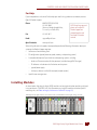
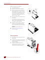
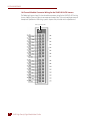
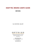
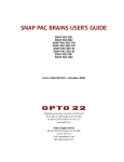
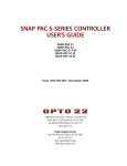
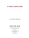
SNAP HIGH-DENSITY
DIGITAL MODULE
USER’S GUIDE
SNAP-IAC-16
SNAP-IAC-A-16
SNAP-IDC-16
SNAP-IDC-32
SNAP-ODC-32-SRC
SNAP-ODC-32-SNK
Form 1547-070720—July, 2007
43044 Business Park Drive • Temecula • CA 92590-3614
Phone: 800-321-OPTO (6786) or 951-695-3000
Fax: 800-832-OPTO (6786) or 951-695-2712
www.opto22.com
Product Support Services
800-TEK-OPTO (835-6786) or 951-695-3080
Fax: 951-695-3017
Email: [email protected]
Web: support.opto22.com
SNAP High-Density Digital Module User’s Guide
Form 1547-070720—July, 2007
Copyright © 2003–2007 Opto 22.
All rights reserved.
Printed in the United States of America.
The information in this manual has been checked carefully and is believed to be accurate; however, Opto 22 assumes no
responsibility for possible inaccuracies or omissions. Specifications are subject to change without notice.
Opto 22 warrants all of its products to be free from defects in material or workmanship for 30 months from the
manufacturing date code. This warranty is limited to the original cost of the unit only and does not cover installation, labor,
or any other contingent costs. Opto 22 I/O modules and solid-state relays with date codes of 1/96 or later are guaranteed for
life. This lifetime warranty excludes reed relay, SNAP serial communication modules, SNAP PID modules, and modules that
contain mechanical contacts or switches. Opto 22 does not warrant any product, components, or parts not manufactured by
Opto 22; for these items, the warranty from the original manufacturer applies. These products include, but are not limited to,
OptoTerminal-G70, OptoTerminal-G75, and Sony Ericsson GT-48; see the product data sheet for specific warranty
information. Refer to Opto 22 form number 1042 for complete warranty information.
Cyrano, Opto 22 FactoryFloor, Optomux, and Pamux are registered trademarks of Opto 22. Generation 4, ioControl, ioDisplay,
ioManager, ioProject, ioUtilities, mistic, Nvio, Nvio.net Web Portal, OptoConnect, OptoControl, OptoDataLink, OptoDisplay,
OptoOPCServer, OptoScript, OptoServer, OptoTerminal, OptoUtilities, PAC Control, PAC Display, PAC Manager, PAC Project,
SNAP Ethernet I/O, SNAP I/O, SNAP OEM I/O, SNAP PAC System, SNAP Simple I/O, SNAP Ultimate I/O, and SNAP Wireless
LAN I/O are trademarks of Opto 22.
ActiveX, JScript, Microsoft, MS-DOS, VBScript, Visual Basic, Visual C++, and Windows are either registered trademarks or
trademarks of Microsoft Corporation in the United States and other countries. Linux is a registered trademark of Linus
Torvalds. Unicenter is a registered trademark of Computer Associates International, Inc. ARCNET is a registered trademark of
Datapoint Corporation. Modbus is a registered trademark of Schneider Electric. Wiegand is a registered trademark of Sensor
Engineering Corporation. Nokia, Nokia M2M Platform, Nokia M2M Gateway Software, and Nokia 31 GSM Connectivity
Terminal are trademarks or registered trademarks of Nokia Corporation. Sony is a trademark of Sony Corporation. Ericsson is
a trademark of Telefonaktiebolaget LM Ericsson.
All other brand or product names are trademarks or registered trademarks of their respective companies or organizations.
ii
SNAP High-Density Digital Module User’s Guide
Table of Contents
Introduction. . . . . . . . . . . . . . . . . . . . . . . . . . . . . . . . . . . . . . . . . . . . . . . . . . . . . . . . . . . . . . . . . . . . . . . . . . . . . . . . 1
Hardware Compatibility . . . . . . . . . . . . . . . . . . . . . . . . . . . . . . . . . . . . . . . . . . . . . . . . . . . . . . . . . . . . . . . . . 2
Field Wiring . . . . . . . . . . . . . . . . . . . . . . . . . . . . . . . . . . . . . . . . . . . . . . . . . . . . . . . . . . . . . . . . . . . . . . . . . . . 2
Interface Terminal for HDD Modules . . . . . . . . . . . . . . . . . . . . . . . . . . . . . . . . . . . . . . . . . . . . . . . . . . . . . . 2
What’s in this Guide? . . . . . . . . . . . . . . . . . . . . . . . . . . . . . . . . . . . . . . . . . . . . . . . . . . . . . . . . . . . . . . . . . . . 2
For Help . . . . . . . . . . . . . . . . . . . . . . . . . . . . . . . . . . . . . . . . . . . . . . . . . . . . . . . . . . . . . . . . . . . . . . . . . . . . . . . 3
Installing Modules . . . . . . . . . . . . . . . . . . . . . . . . . . . . . . . . . . . . . . . . . . . . . . . . . . . . . . . . . . . . . . . . . . . . . . . . . . 3
Removing Modules . . . . . . . . . . . . . . . . . . . . . . . . . . . . . . . . . . . . . . . . . . . . . . . . . . . . . . . . . . . . . . . . 4
Attaching the Wiring Harness . . . . . . . . . . . . . . . . . . . . . . . . . . . . . . . . . . . . . . . . . . . . . . . . . . . . . . . . . . . . 5
Building Your Own Wiring Harness . . . . . . . . . . . . . . . . . . . . . . . . . . . . . . . . . . . . . . . . . . . . . . . . . . . 5
16-Channel Module Connector Wiring for the SNAP-HD-ACF6 harness . . . . . . . . . . . . . . . . . . . 6
32-Channel Module Connector Wiring for the SNAP-HD-CBF6 Harness . . . . . . . . . . . . . . . . . . . 7
Module Connector Pinouts . . . . . . . . . . . . . . . . . . . . . . . . . . . . . . . . . . . . . . . . . . . . . . . . . . . . . . . . . . . . . . 8
Pinouts—16-Channel Digital Input Modules . . . . . . . . . . . . . . . . . . . . . . . . . . . . . . . . . . . . . . . . . . 8
Pinouts—32-Channel Digital Input Modules . . . . . . . . . . . . . . . . . . . . . . . . . . . . . . . . . . . . . . . . . . 9
Pinouts—32-Channel Digital Output Modules . . . . . . . . . . . . . . . . . . . . . . . . . . . . . . . . . . . . . . . 10
Configuring Breakout Racks . . . . . . . . . . . . . . . . . . . . . . . . . . . . . . . . . . . . . . . . . . . . . . . . . . . . . . . . . . . . . . . . 11
Configuring a SNAP-IDC-HDB Input Breakout Rack . . . . . . . . . . . . . . . . . . . . . . . . . . . . . . . . . . . . . . . . 11
Setting the SNAP-IDC-HDB Jumpers . . . . . . . . . . . . . . . . . . . . . . . . . . . . . . . . . . . . . . . . . . . . . . . . . 11
Wiring the SNAP-IDC-HDB . . . . . . . . . . . . . . . . . . . . . . . . . . . . . . . . . . . . . . . . . . . . . . . . . . . . . . . . . 12
Configuring a SNAP-ODC-HDB Output Breakout Rack . . . . . . . . . . . . . . . . . . . . . . . . . . . . . . . . . . . . . . 12
Setting the SNAP-ODC-HDB Jumpers . . . . . . . . . . . . . . . . . . . . . . . . . . . . . . . . . . . . . . . . . . . . . . . . 13
Connecting Power to the SNAP-ODC-HDB . . . . . . . . . . . . . . . . . . . . . . . . . . . . . . . . . . . . . . . . . . . 13
Connecting Field Devices to the SNAP-ODC-HDB . . . . . . . . . . . . . . . . . . . . . . . . . . . . . . . . . . . . . . 14
Testing Field Connections . . . . . . . . . . . . . . . . . . . . . . . . . . . . . . . . . . . . . . . . . . . . . . . . . . . . . . . . . . . . . . 14
Reading Point States . . . . . . . . . . . . . . . . . . . . . . . . . . . . . . . . . . . . . . . . . . . . . . . . . . . . . . . . . . . . . . 14
Writing to Output Points . . . . . . . . . . . . . . . . . . . . . . . . . . . . . . . . . . . . . . . . . . . . . . . . . . . . . . . . . . . 16
What’s Next? . . . . . . . . . . . . . . . . . . . . . . . . . . . . . . . . . . . . . . . . . . . . . . . . . . . . . . . . . . . . . . . . . . . . . . . . . . . . . 18
SNAP High-Density Digital Module User’s Guide
iii
iii
Notes on Legacy Hardware and Software. . . . . . . . . . . . . . . . . . . . . . . . . . . . . . . . . . . . . . . . . . . . . . . . . . . . . 19
Using HDD Modules with Legacy Hardware . . . . . . . . . . . . . . . . . . . . . . . . . . . . . . . . . . . . . . . . . . . . . . .19
Using HDD Modules with Legacy Software . . . . . . . . . . . . . . . . . . . . . . . . . . . . . . . . . . . . . . . . . . . . . . . .19
Connecting to G4 Digital I/O . . . . . . . . . . . . . . . . . . . . . . . . . . . . . . . . . . . . . . . . . . . . . . . . . . . . . . . . . . . .20
Comparing High-Density and 4-Channel Digital Modules . . . . . . . . . . . . . . . . . . . . . . . . . . . . . . . . . . . . . . 20
Communication with the Processor . . . . . . . . . . . . . . . . . . . . . . . . . . . . . . . . . . . . . . . . . . . . . . . . . . . . . .20
Counting . . . . . . . . . . . . . . . . . . . . . . . . . . . . . . . . . . . . . . . . . . . . . . . . . . . . . . . . . . . . . . . . . . . . . . . . . . . . .21
Use in PAC Control . . . . . . . . . . . . . . . . . . . . . . . . . . . . . . . . . . . . . . . . . . . . . . . . . . . . . . . . . . . . . . . . . . . . .21
High-Density and 4-Channel Digital Module
Comparison Chart . . . . . . . . . . . . . . . . . . . . . . . . . . . . . . . . . . . . . . . . . . . . . . . . . . . . . . . . . . . . . . . . .22
Specifications . . . . . . . . . . . . . . . . . . . . . . . . . . . . . . . . . . . . . . . . . . . . . . . . . . . . . . . . . . . . . . . . . . . . . . . . . . . . . 23
Input Modules . . . . . . . . . . . . . . . . . . . . . . . . . . . . . . . . . . . . . . . . . . . . . . . . . . . . . . . . . . . . . . . . . . . . . . . . .23
Output Modules . . . . . . . . . . . . . . . . . . . . . . . . . . . . . . . . . . . . . . . . . . . . . . . . . . . . . . . . . . . . . . . . . . . . . . .24
Breakout Racks . . . . . . . . . . . . . . . . . . . . . . . . . . . . . . . . . . . . . . . . . . . . . . . . . . . . . . . . . . . . . . . . . . . . . . . .25
Wiring Harnesses and Cables . . . . . . . . . . . . . . . . . . . . . . . . . . . . . . . . . . . . . . . . . . . . . . . . . . . . . . . . . . . .25
Dimensional Drawings . . . . . . . . . . . . . . . . . . . . . . . . . . . . . . . . . . . . . . . . . . . . . . . . . . . . . . . . . . . . . . . . . . . . . 26
SNAP 16-Channel Digital Modules . . . . . . . . . . . . . . . . . . . . . . . . . . . . . . . . . . . . . . . . . . . . . . . . . . . . . . .26
SNAP 32-Channel Digital Modules . . . . . . . . . . . . . . . . . . . . . . . . . . . . . . . . . . . . . . . . . . . . . . . . . . . . . . .27
SNAP 32-Channel Digital Modules (continued) . . . . . . . . . . . . . . . . . . . . . . . . . . . . . . . . . . . . . . . . . . . .28
SNAP 32-Channel Digital Modules (continued) . . . . . . . . . . . . . . . . . . . . . . . . . . . . . . . . . . . . . . . . . . . .29
Breakout Racks for 32-Channel Digital Modules . . . . . . . . . . . . . . . . . . . . . . . . . . . . . . . . . . . . . . . . . . . .30
iv
SNAP High-Density Digital Module User’s Guide
Chapter 2
SNAP High-Density Digital
Module User’s Guide
Introduction
SNAP high-density digital modules from Opto 22 provide 16 or 32 channels (also referred to as
points) on one compact SNAP input or output module.
These modules are ideal for OEMs and others
who have applications with high point counts,
or for any application requiring a large number
of digital points on one SNAP I/O rack.
The following high-density digital modules are
available:
•
The SNAP-IDC-32 digital input module,
with 32 input points, can be used to sense
on/off status for 10–32 VDC inputs from
sources such as proximity switches, limit
switches, push buttons, and pilot switches.
•
The SNAP-IDC-16 digital input module
offers 16 points with channel-to-channel
isolation. It can sense on/off status
for10–32 VDC/VAC loads.
•
SNAP-IAC-16 and SNAP-IAC-A-16 digital
input modules each have 16 points with
channel-to-channel isolation. These
modules sense on/off status for
90–140 VAC (SNAP-IAC-16)
or180–280 VAC (SNAP-IAC-A-16).
•
SNAP-ODC-32-SRC and
SNAP-ODC-32-SNK digital output
modules have 32 points and can switch on
and off 5–60 VDC loads, either sourcing or
sinking.
SNAP-IDC-16
SNAP-ODC-32-SNK
SNAP High-Density Digital Module User’s Guide
11
INTRODUCTION
Hardware Compatibility
SNAP high-density digital (HDD) modules are part of the SNAP PAC System. They are designed to
mount on a SNAP PAC rack with a SNAP PAC brain or R-series controller. Analog, serial,
special-purpose, and 4-channel digital modules can be mounted on the same rack to provide the
mix of signals and density needed at any distributed location.
(For information on using HDD modules with older processors or racks, see “Notes on Legacy
Hardware and Software” on page 19.)
Field Wiring
Two options are available separately for connecting field wiring to the module:
•
Wiring harness assembly with flying leads (32- and 16-channel modules). Use the
SNAP-HD-CBF6 for 32-channel modules and the SNAP-HD-ACF6 for 16-channel modules.
The wiring harness plugs into connectors on the module’s top. Use one wiring harness per
module.
•
Breakout racks and cables (32-channel modules only). Fused breakout racks are also
available separately to make wiring easier. SNAP-IDC-HDB is for input modules, and
SNAP-ODC-HDB is for output modules. Use one rack per module. Connect the 32-channel
module to either breakout rack using the SNAP-HD-BF6 header cable.
Interface Terminal for HDD Modules
The optional OptoTerminal-G20 operator interface terminal (available separately) is
recommended for commissioning and troubleshooting. It plugs into a connector on the top of the
module. The OptoTerminal-G20 displays the status of a high-density digital module’s points on a
two-line LCD display and can also be used to turn output points on and off.
What’s in this Guide?
This guide includes the following sections:
2
•
Installation and testing
•
Comparison with 4-channel SNAP digital modules
•
Specifications and dimensions
SNAP High-Density Digital Module User’s Guide
CHAPTER 2: SNAP HIGH-DENSITY DIGITAL MODULE USER’S GUIDE
For Help
If you have problems and cannot find the help you need in this guide or on our website, contact
Opto 22 Product Support.
Phone:
800-TEK-OPTO (835-6786)
951-695-3080
(Hours are Monday through Friday,
7 a.m. to 5 p.m. Pacific Time)
Fax:
951-695-3017
Email:
[email protected]
Opto 22 website:
www.opto22.com
NOTE: Email messages and
phone calls to Opto 22
Product Support are
grouped together and
answered in the order
received.
When calling for technical support, be prepared to provide the following information about your
system to the Product Support engineer:
•
Software and version being used
•
PC configuration (type of processor, speed, memory, and operating system)
•
A complete description of your hardware and operating systems, including:
– loader and firmware versions for the processor (available through PAC Manager)
– IP addresses and subnet masks for devices on the system
– type of power supply
– third-party devices installed (for example, barcode readers)
•
Specific error messages seen
Installing Modules
As shown below, high-density digital (HDD) modules can be mixed with other modules and placed
in any position on a SNAP PAC rack. (For information on using HDD modules with other Opto 22
mounting racks, see “Notes on Legacy Hardware and Software” on page 19.)
SNAP high-density digital modules can be mixed on the rack with SNAP 4-channel digital, analog, and serial
SNAP High-Density Digital Module User’s Guide
33
INSTALLING MODULES
Follow these steps to install modules:
1. Turn off power to the rack.
2. Remove the module from its packaging.
3. Position the module over the connector on
the rack, aligning the small slot at the base
of the module with the retention bar on the
rack. If it is next to another module, make
sure the male and female module keys are
aligned, as shown at right.
4. Push straight down on the module to snap it
into position.
The module snaps securely into place and
requires a special tool (provided) to remove
it. To remove a module, see below.
5. (Optional) As shown at right, use standard
4-40 x 1/4 truss-head Phillips hold-down
screws to secure both sides of each module.
CAUTION: Do not over-tighten screws.
6. Continue with “Attaching the Wiring
Harness” on page 5.
Removing Modules
1. If the modules are held in place with screws,
remove them.
2. As shown in the illustration, insert the SNAP
module tool (provided) into the notch at the
base of the module.
3. Squeeze the module tool against the
module to open the release latch, and pull
straight up on the module to remove it.
4
SNAP High-Density Digital Module User’s Guide
CHAPTER 2: SNAP HIGH-DENSITY DIGITAL MODULE USER’S GUIDE
Attaching the Wiring Harness
A wiring harness assembly (SNAP-HD-ACF6 for 16-channel modules or SNAP-HD-CBF6 for
32-channel modules) is sold separately and used to wire field devices to the module. One wiring
harness assembly is needed per module.
NOTE: Opto 22 also offers SNAP-IDC-HDB and SNAP-ODC-HDB fused breakout racks for 32-channel
digital modules. If you are using a breakout rack, see “Configuring Breakout Racks” on page 11 for
installation instructions.
1. Plug the wiring harness into the wiring connector(s) on the top of the module. Secure the
harness cable so that its weight is supported. The connector plug is not designed to support
the weight of the cable.
2. (Recommended) Install a barrier strip in a convenient location for ease in wiring the connector
to field devices.
3. To wire field devices to the module, do the following:
– For 16-channel modules, follow “16-Channel Module Connector Wiring for the
SNAP-HD-ACF6 harness” on page 6 and “Pinouts—16-Channel Digital Input Modules” on
page 8.
– For 32-channel input modules, follow “32-Channel Module Connector Wiring for the
SNAP-HD-CBF6 Harness” on page 7 and “Pinouts—32-Channel Digital Input Modules” on
page 9.
– For 32-channel output modules, follow wiring and fusing diagrams in “32-Channel Module
Connector Wiring for the SNAP-HD-CBF6 Harness” on page 7 and “Pinouts—32-Channel
Digital Output Modules” on page 10.
CAUTION: For output modules, you must install fuses between the wiring harness and field
devices. If you use a fused breakout rack (part number SNAP-ODC-HDB), fusing is already done for
you. If not, follow the diagram on page 10 to either fuse the common for each set of wires or fuse
individual pinouts for each point.
Building Your Own Wiring Harness
If you want to build your own wiring harness you will need the parts listed below.
For SNAP-HD-ACF6:
Connector: Molex 39-01-2165
Pins: Molex 39-00-0214
Cable: Belden 8308 (22 AWG, 16 conductor, shielded) or equivalent (UL AWM style 2464)
For SNAP-HD-CBF6:
Connector: Molex 15-04-5401
Pin housing: Molex 50-57-9320
Pins: Molex p/n 16-02-0103
Cable: Alpha 5020/40c (24 AWG, 40 conductor) or equivalent (UL type CM)
SNAP High-Density Digital Module User’s Guide
55
INSTALLING MODULES
16-Channel Module Connector Wiring for the SNAP-HD-ACF6 harness
The following diagram shows16-channel module connector wiring for the SNAP-HD-ACF6 wiring
harness. Note that the small four-pin connector on the top of the 16-channel module connects to
the optional OptoTerminal-G20 using a special adapter cable, included with the OptoTerminal.
Port for OptoTerminal-G20
6
SNAP High-Density Digital Module User’s Guide
CHAPTER 2: SNAP HIGH-DENSITY DIGITAL MODULE USER’S GUIDE
32-Channel Module Connector Wiring for the SNAP-HD-CBF6 Harness
The following table shows 32-channel module connector wiring for the SNAP-HD-CBF6 wiring
harness. Wires from the wiring harness are grouped into four sets. Each set contains color-coded
wires.
Set A
Wires
Set B
Ch
Wires
A0
Gray
0
B0
Gray
A1
Blue
1
B1
A2
Yellow
2
B2
Yellow
A3
Red
3
B3
A4
White
4
A5
Violet
A6
A7
Set C
Point
8
Wires
Set D
Point
Wires
Ch
C0
Gray
16
D0
Gray
24
C1
Blue
17
D1
Blue
25
10
C2
Yellow
18
D2
Yellow
26
Red
11
C3
Red
19
D3
Red
27
B4
White
12
C4
White
20
D4
White
28
5
B5
Violet
13
C5
Violet
21
D5
Violet
29
Green
6
B6
Green
14
C6
Green
22
D6
Green
30
Orange
7
B7
Orange
15
C7
Orange
23
D7
Orange
31
Blue
9
The four sets relate to point numbers on the module as shown below. For a pinout diagram of the
input modules, see page 9. For output modules, see page 10.
Harness
Pin
Wire Color Number
Gray
40
Blue
38
Yellow
36
Red
34
Black
32
Gray
30
Blue
28
Yellow
26
Red
24
Black
22
Gray
20
Blue
18
Yellow
16
Red
14
Black
12
Gray
10
Blue
8
Yellow
6
Red
4
Black
2
Signal
A0
A1
A2
A3
ACOM
B0
B1
B2
B3
BCOM
C0
C1
C2
C3
CCOM
D0
D1
D2
D3
DCOM
Signal
A4
A5
A6
A7
ACOM
B4
B5
B6
B7
BCOM
C4
C5
C6
C7
CCOM
D4
D5
D6
D7
DCOM
Pin
Number
39
37
35
33
31
29
27
25
23
21
19
17
15
13
11
9
7
5
3
1
Harness
Wire Color
White
Violet
Green
Orange
Brown
White
Violet
Green
Orange
Brown
White
Violet
Green
Orange
Brown
White
Violet
Green
Orange
Brown
Connector wiring for SNAP-ODC-32-SNK, SNAP-ODC-32-SRC, and
SNAP-IDC-32 high-density digital modules (top view of module)
SNAP High-Density Digital Module User’s Guide
77
INSTALLING MODULES
Module Connector Pinouts
Pinouts—16-Channel Digital Input Modules
The following pintout diagram applies to the SNAP-IDC-16, SNAP-IAC-16 and SNAP-IAC-A-16
modules
NOTE: The connectors on these
modules are not polarity-specific. You
can connect the positive lead (+) for
each channel (or point) to either L1 or
L2, and this can vary from point to
point on the module.
8
SNAP High-Density Digital Module User’s Guide
CHAPTER 2: SNAP HIGH-DENSITY DIGITAL MODULE USER’S GUIDE
Pinouts—32-Channel Digital Input Modules
The following pintout diagram applies to the SNAP-IDC-32 module.
IMPORTANT: The SNAP-IDC-32
module is polarity-specific, and must
be wired in “source” configuration as
shown. Do not wire the SNAP-IDC-32
module in “sinking” configuration.
SNAP High-Density Digital Module User’s Guide
99
INSTALLING MODULES
Pinouts—32-Channel Digital Output Modules
The 32-channel digital output modules include the SNAP-ODC-32-SRC and SNAP-ODC-32-SNK.
All groups must be fused.
10
SNAP High-Density Digital Module User’s Guide
CHAPTER 2: SNAP HIGH-DENSITY DIGITAL MODULE USER’S GUIDE
Configuring Breakout Racks
This section describes how to configure a SNAP-IDC-HDB input breakout rack (below) or a
SNAP-ODC-HDB breakout rack (see page 12).
Configuring a SNAP-IDC-HDB Input Breakout Rack
To use a SNAP-IDC-HDB breakout rack with a SNAP-IDC-32 input module, connect the rack to the
module using the SNAP-HD-BF6 header cable. Set the jumpers, and wire the field devices and the
power supply, as described below.
There are four identical zones on the rack, labeled “A” through “D”.
Setting the SNAP-IDC-HDB Jumpers
Set the LED jumpers for the SNAP-IDC-HDB breakout rack to the X position when using the
SNAP-IDC-32 input module.
JP-D
JP-C
JP-B
JP-A
X
X
X
X
Z
Z
Z
Z
Set jumpers to the X position.
SNAP High-Density Digital Module User’s Guide
11
11
CONFIGURING BREAKOUT RACKS
Wiring the SNAP-IDC-HDB
Connect the field devices and power supply to the SNAP-IDC-HDB input breakout board as shown
here.
IMPORTANT: See module technical specifications for signal voltage range.
Configuring a SNAP-ODC-HDB Output Breakout Rack
To use a SNAP-ODC-HDB breakout rack with a SNAP-ODC-32-SRC or SNAP-ODC-32-SNK output
module, connect the rack to the module using the SNAP-HD-BF6 header cable. Set the jumpers, and
wire the power supply and the field devices, as described below.
There are four identical zones on the rack, labeled “A” through “D”.
12
SNAP High-Density Digital Module User’s Guide
CHAPTER 2: SNAP HIGH-DENSITY DIGITAL MODULE USER’S GUIDE
Setting the SNAP-ODC-HDB Jumpers
Set the LED jumpers for the SNAP-ODC-HDB breakout rack to the Z position when using either the
SNAP-ODC-32-SRC or SNAP-ODC-32-SNK output module.
JP-D
X
Z
JP-C
JP-B
JP-A
X
X
X
Z
Z
Z
Set jumpers to the Z position.
Connecting Power to the SNAP-ODC-HDB
Connect the power supply to the SNAP-ODC-HDB output breakout board as shown here.
SNAP-ODC-32-SRC
+
–
Connect the positive lead (+)
from the power supply to one
Module COM terminal. Connect
the negative lead (–) to one
Field COM terminal.
Module Field
COM
COM
SNAP-ODC-32-SNK
–
+
Connect the negative lead (–)
from the power supply to one
Module COM terminal. Connect
the positive lead (+) to one
Field COM terminal.
Module Field
COM
COM
SNAP High-Density Digital Module User’s Guide
13
13
CONFIGURING BREAKOUT RACKS
Connecting Field Devices to the SNAP-ODC-HDB
Connect the field devices to the SNAP-ODC-HDB output breakout board as shown here.
IMPORTANT: See module technical specifications for signal voltage range.
Testing Field Connections
The OptoTerminal-G20 (sold separately) is recommended for testing field wiring locally. For input
and output modules, you can use it to read point states; for output modules, you can also use it to
write to individual output points.
CAUTION: The OptoTerminal-G20 is for use with SNAP high-density modules only, and is the only display
device intended for use with these modules. Any use of the display device on other equipment, or the use
of another display device with a high-density digital module, may damage your equipment.
Reading Point States
1. Turn on power to the rack.
2. Use the correct cable to connect the OptoTerminal-G20 to the RJ-45 connector on a 32-channel
module or the 4-pin connector on a 16-channel module.
14
SNAP High-Density Digital Module User’s Guide
CHAPTER 2: SNAP HIGH-DENSITY DIGITAL MODULE USER’S GUIDE
As shown in the diagram below, the OptoTerminal-G20 displays the current state of all points
on the module.
Wiring harness not shown
Point states are displayed as a bitmask. Each binary digit represents the state of one point,
either on (1) or off (o). The top row shows points 31–16 and the bottom row shows points
15–0.
In the following example, points 0, 2, 4, 5, 9, 12, 13, 15, 17, 18, 19, 22, 23, 26, 28, and 30 are on,
and the remaining points are off. The terminal displays the bitmask in binary format; the
hexadecimal equivalent of the bitmask is shown for reference only.
SNAP High-Density Digital Module User’s Guide
15
15
CONFIGURING BREAKOUT RACKS
Writing to Output Points
1. Turn off power to the rack.
2. Remove the SNAP brain or controller from the rack to prevent it from overwriting commands
from the OptoTerminal-G20. (Commands from the display device have the lowest priority.)
3. Turn on power to the rack.
4. Plug the OptoTerminal-G20 into the RJ-45 connector on top of the output module.
The terminal shows the current state of output points. In this example, all points are off:
5. Press the arrow keys to select the point you want to turn on or off.
Up and down arrows move the cursor between rows.
Left and right arrows move the cursor to select a point.
6. When you have selected the point, press ENT.
7. To turn a point on, press the up or down arrow to select a 1. To turn a point off, press the up or
down arrow to select a 0.
NOTE: The OptoTerminal-G20 displays 1 and o for On and Off. A zero is displayed when the value of
zero is selected to be written to a point.
8. Press ENT to send the Turn On or Turn Off command.
If you don’t press ENT, the unfinished command is cancelled after 10 seconds, and the display is
reset.
16
SNAP High-Density Digital Module User’s Guide
CHAPTER 2: SNAP HIGH-DENSITY DIGITAL MODULE USER’S GUIDE
9. Watch the output device to make sure it responds.
After the command is sent, the display shows the changed value.
SNAP High-Density Digital Module User’s Guide
17
17
WHAT’S NEXT?
What’s Next?
Once you have installed and tested the high-density digital module, it is ready for use. Configuration,
reading, and writing using PAC Project are similar to 4-channel modules. For differences, see
“Comparing High-Density and 4-Channel Digital Modules” on page 20.
You’ll find the following guides useful for the information listed. All guides are available on the
Opto 22 website, www.opto22.com. The easiest way to locate one is to search on its form number.
For this information
Form #
SNAP PAC Brain User’s Guide
1590
SNAP PAC R-Series Controller User’s Guide
1595
PAC Control User’s Guide
1700
PAC Control Command Reference
1701
PAC Control Commands Quick Reference
1703
One-time reads and writes to high-density modules
PAC Manager User’s Guide
1704
Reading and writing to high-density modules using a
custom program you develop
OptoMMP Protocol Guide
1465
Installing and using the I/O processors (brains and
rack-mounted controllers) that support high-density
modules
Reading and writing to high-density modules using
PAC Control strategies
18
See this guide
SNAP High-Density Digital Module User’s Guide
CHAPTER 2: SNAP HIGH-DENSITY DIGITAL MODULE USER’S GUIDE
Notes on Legacy Hardware and Software
For important information on mixing current and legacy products, see Opto 22 form #1688, the
SNAP PAC System Migration Technical Note.
Using HDD Modules with Legacy Hardware
Most high-density digital modules can be used only with SNAP PAC brains and R-series controllers.
However, the following table lists some HDD modules that can be installed on I/O units using legacy
I/O processors and racks:
These HDD Modules...
SNAP-IDC-32
SNAP-ODC-32-SNK
SNAP-ODC-32-SRC
...can be used with these
legacy processors*
...on these racks
SNAP-UP1-M64
SNAP-ENET-S64
SNAP-M16
SNAP-M32
SNAP-M48
SNAP-M64
SNAP-UP1-ADS
SNAP-B3000-ENET
SNAP-ENET-RTC
SNAP-B4M
SNAP-B8M
SNAP-B8MC
SNAP-B8MC-P
SNAP-B12M
SNAP-B12MC
SNAP-B12MC-P
SNAP-B16M
SNAP-B16MC
SNAP-B16MC-P
*Processors must have firmware 6.1 or higher.
Support for these HDD modules on legacy hardware is limited. See form #1688, the SNAP PAC System
Migration Technical Note, for more information.
To check processor firmware and load new firmware if required, follow instructions in the PAC
Manager User’s Guide, Legacy Edition (form #1714).
Note that SNAP high-density modules cannot be used with digital-only processors, because
high-density modules communicate with the processor as an analog or special-purpose module
communicates.
HDD modules can be placed anywhere on B-series racks, even in slots marked “Analog Only.”
Using HDD Modules with Legacy Software
It is best to use PAC Control 8.0 or newer with HDD modules, because you can configure them as you
would other digital modules and read and write to them using standard digital point commands.
However, you can use ioControl version 6.1 or newer with the SNAP-IDC-32, SNAP-ODC-32-SNK, and
SNAP-ODC-32-SRC modules. Use the separate HDD commands for reading and writing.
Similarly, PAC Manager 8.0 is required for the best use of HDD modules, but you can also use
ioManager 6.1 or newer for one-time reads and writes to the same three modules.
If you must read and write to these three modules using ioDisplay 6.0 (not recommended; upgrade
to PAC Display or at least to ioDisplay 6.1), see Opto 22 form #1561, Using ioDisplay 6.0 with SNAP
32-channel Digital Modules Technical Note.
SNAP High-Density Digital Module User’s Guide
19
19
COMPARING HIGH-DENSITY AND 4-CHANNEL DIGITAL MODULES
Connecting to G4 Digital I/O
SNAP-HD-G4F6 header cable
SNAP 32-point
module
G4PB16 mounting racks
SNAP mounting rack
SNAP high-density digital output modules can connect to G4PB16 mounting racks using the
SNAP-HD-G4F6 header cable. This cable allows older G4 digital output I/O systems to take
advantage of modern Opto 22 products like SNAP PAC controllers, SNAP PAC brains, and PAC Project
software. The header cable connects two G4PB16, G4PB16H, or G4PB16HC mounting racks to one
high-density digital output module.
Comparing High-Density and 4-Channel Digital Modules
SNAP high-density digital modules differ in several ways from 4-channel SNAP digital modules. A
few important differences are discussed below; see the table on the next page for more.
Communication with the Processor
One of the main differences between 4-channel and high-density modules is in how the processor
(brain or on-the-rack controller) communicates with them on the mounting rack. Four-channel
SNAP digital modules communicate with the processor through direct wiring; but SNAP
high-density modules communicate as analog and serial modules do, over an internal bus built into
the rack and using the processor’s analog scanner.
This different communication method means that:
20
•
Communication with the processor (update time) is generally slower.
•
Communication speed is affected by how “busy” the processor is—that is, how many modules
it talks to and how many Ethernet communications the processor is handling at the same time.
SNAP High-Density Digital Module User’s Guide
CHAPTER 2: SNAP HIGH-DENSITY DIGITAL MODULE USER’S GUIDE
Counting
Another difference between 4-channel and high-density digital modules is in counting. For
4-channel SNAP digital input modules, counting is done on the processor. We refer to it as
“high-speed” counting because it can be up to 20 KHz, depending on the speed of the module.
For high-density SNAP digital modules, however, the module itself does the counting. The module
uses a 16-bit counter (which goes up to 65,535), but the processor used with the module
accumulates counts to 32 bits (4,294,967,295) by periodically getting and clearing the module’s
counts and adding each new count to what it already has for each point. Update time varies based
on the number of modules on the rack and Ethernet communication demands placed on the
processor.
Counting speed for high-density digital modules is up to 50 Hz at a 50% duty cycle. This rate is useful
for applications that require counting at lower speeds—for example, rotating shafts, flow meters
that generate pulses, and electrical meters tuned to slower speeds.
Because counting is done in the module rather than in the processor, you can get counts for HDD
modules used with SNAP-PAC-R2 controllers and SNAP-PAC-EB2 brains—processors that don’t have
high-speed counting capability.
Use in PAC Control
SNAP high-density modules are configured and used in PAC Control just like 4-channel digital
modules. (Exception: if you are using older hardware, see “Using HDD Modules with Legacy
Hardware” on page 19.)
If you want to use a point as a counter, configure it as a counter and use the standard PAC Control
commands for counters, such as Start Counter and Get and Clear Counter. However, because counting
is automatic and continuous on the high-density module, be sure you clear the counter each time
before starting to use it, so you know it’s starting from zero.
SNAP High-Density Digital Module User’s Guide
21
21
COMPARING HIGH-DENSITY AND 4-CHANNEL DIGITAL MODULES
High-Density and 4-Channel Digital Module
Comparison Chart
The following chart summarizes differences between high-density and 4-channel SNAP digital
modules.
Item
SNAP High-Density Digital Modules
4-Channel SNAP Digital Modules
Number of points on
module
16 or 32, depending on module
4
Isolation and fusing
16-point input modules: Each point is optically
isolated from other points on the module.
32-point input and output modules: The module
is divided into four groups of eight points. Groups
are isolated from each other, but points within a
group are not isolated from each other. Groups
must be externally fused.
Input modules: Each point is optically isolated from
other points on the module.
Most output modules: Points are not isolated from
each other. Points share a common fuse. See the
SNAP Digital Ouput Modules Data Sheet (form
#1144) for isolated modules.
Status LEDs
None; use the handheld OptoTerminal-G20 for
module diagnostics and commissioning, or for
32-point modules, connect to an optional breakout
rack.
One for each point, located on top of module.
2–30 ms typical2
0.5–2 ms typical2
16-point input modules: 15–20 ms
32-point input modules: 6 ms
Output modules: 100 microseconds
Varies by module. Examples:
• SNAP-IDC5-FAST: 25 microseconds
• SNAP-IDC5: 5 ms turn-on, 15 ms turn-off
Polling time from I/O
processor to module1
Module turn-on/off
time1
Latching
Yes
Counting on digital
input modules
Counting occurs on the module.3
Counting is available with any compatible I/O
processor (including SNAP-PAC-R2 and
SNAP-PAC-EB2).
Counting speeds:
On 32-point modules, 0–50 Hz @ 50% duty cycle
On 16-point modules, 0–25 Hz @ 50% duty cycle
Yes
High-speed counting occurs on the I/O processor
(brain or on-the-rack controller) and can be
configured for any point. (High-speed counting is
available on SNAP-PAC-R1 and SNAP-PAC-EB1
processors.)
Counting speed varies based on the processor and
the speed of the module. Example: SNAP-PAC-EB1
brain with SNAP-IDC5-FAST: up to 20 KHz
1 Actual turn-on and turn-off times equal the polling time plus the module time.
2 Polling time varies based on the SNAP I/O processor (brain or on-the-rack controller), processor configuration, and Ethernet host
communication activity.
3 The high-density digital module uses a 16-bit counter, but the processor used with the module accumulates counts to 32 bits by
periodically getting and clearing the module’s counts and adding to current values. Update time varies based on number of
modules and Ethernet communication demands.
22
SNAP High-Density Digital Module User’s Guide
CHAPTER 2: SNAP HIGH-DENSITY DIGITAL MODULE USER’S GUIDE
Specifications
Input Modules
SNAP-IDC-32
SNAP-IDC-16
SNAP-IAC-16
SNAP-IAC-A-16
Input Range
10–32 VDC
10–32 VDC/VAC
90–140 VAC/VDC
180–280 VAC/VDC
Input Resistance
20 K ohms
44 K ohms
300 K ohms
940 K ohms
Logic Voltage and
Current
5 VDC ± 0.1 @ 150 mA
5 VDC ± 0.1 @ 150 mA
5 VDC ± 0.1 @ 150 mA
5 VDC ± 0.1 @
150 mA
Input Arrangement
32 input channels; 4
groups of 8 inputs each
(Points in each group
share a common
negative connection.)
16 isolated input
channels
16 isolated input
channels
16 isolated input
channels
Channel-to-Channel
Isolation
No channel-to-channel
isolation; 100 V
group-to-group isolation
250 V working, 1500 V
transient
250 V working, 1500 V
transient
250 V working,
1500 V transient
Maximum Number of
HDD Modules on One
Mounting Rack
16
16
16
16
Indicators
None; use optional
OptoTerminal-G20
diagnostic display or
breakout rack.
None; use optional
OptoTerminal-G20
diagnostic display.
None; use optional
OptoTerminal-G20
diagnostic display.
None; use optional
OptoTerminal-G20
diagnostic display.
ON Voltage
10 VDC @ 0.5 mA
10 VDC @ 0.230 mA
90 VDC @ 0.3 mA
180 VDC @ 0.191 mA
OFF Voltage
3 VDC @ 0.1 mA
3 VDC @ 0.05 mA
40 VDC @ 0.135 mA
40 VDC @ 0.043 mA
2–30 ms typical2
2–30 ms typical2
2–30 ms typical2
2–30 ms typical2
Input Turn-On/Off Time
6 ms
15 ms turn-on time
20 ms turn-off time
15 ms turn-on time
20 ms turn-off time
15 ms turn-on time
20 ms turn-off time
Counting Frequency
(DC input)
0–50 Hz @ 50% duty
cycle
0–25 Hz @ 50% duty
cycle
0–25 Hz @ 50% duty
cycle
0–25 Hz @ 50% duty
cycle
Polling time from I/O
processor to module1
1 Affects turn-on and turn-off determination
2 Time varies based on the SNAP PAC I/O processor (brain or on-the-rack controller), processor configuration, and Ethernet host
communication activity.
SNAP High-Density Digital Module User’s Guide
23
23
SPECIFICATIONS
Output Modules
SNAP-ODC-32-SRC
SNAP-ODC-32-SNK
Line Voltage
4–24 VDC
4–24 VDC
Logic Voltage and Current
5 VDC ± 0.1 @ 150 mA
5 VDC ± 0.1 @ 150 mA
Output Arrangement
32 output channels; 4 groups of 8 outputs
each. Points in each group share a common
positive connection.
32 output channels; 4 groups of 8 outputs
each. Points in each group share a common
negative connection.
Maximum Number of HDD
Modules on One Mounting Rack
16
16
Indicators
None; use optional OptoTerminal-G20
diagnostic display or breakout rack.
None; use optional OptoTerminal-G20
diagnostic display or breakout rack.
2–30 ms typical2
2–30 ms typical2
Output Turn-On/Off Time
100 microseconds
100 microseconds
Maximum Load per Point
0.25 A
0.25 A
Forward Drop
0.15 VDC @ 0.25 A
0.15 VDC @ 0.25 A
Maximum Off State Voltage
60 VDC
60 VDC
Reverse Voltage
0.6 VDC
0.6 VDC
Surge (1 sec.)
1A
1A
Polling time from I/O processor to
module1
1 Affects turn-on and turn-off determination
2 Time varies based on the SNAP PAC I/O processor (brain or on-the-rack controller), processor configuration, and Ethernet host
communication activity.
24
SNAP High-Density Digital Module User’s Guide
CHAPTER 2: SNAP HIGH-DENSITY DIGITAL MODULE USER’S GUIDE
Breakout Racks
SNAP-IDC-HDB Breakout Rack for High-Density Digital Input Module
Used with
SNAP-IDC-32
Connectors
40-pin header connects to SNAP-IDC-32 module using SNAP-HD-BF6 header cable.
32 signal input connectors; each signal connector has a corresponding common connector.
For each zone of 8 signal inputs, 1 connection for either module common or field common.
Indicators
1 LED for each signal input (32 signal LEDs total)
1 power status LED for each zone of 8 signal inputs (4 power LEDs total)
Fusing
1 A fuses; 2 fuses for each zone of 8 signal inputs (8 fuses total)
Replace with Pudenz 1 A automobile mini-fuse or equivalent.
Jumpers
For each zone of 8 signal inputs, 1 jumper controls whether module common or field common
is used.
SNAP-ODC-HDB Breakout Rack for High-Density Digital Output Modules
Used with
SNAP-ODC-32-SRC
SNAP-ODC-32-SNK
Connectors
40-pin header; connects to SNAP-ODC-32-SRC or SNAP-ODC-32-SNK module using
SNAP-HD-BF6 header cable.
32 signal output connectors; each signal connector has a corresponding common connector.
For each zone of 8 signal outputs, 1 connection for either module common or field common.
Indicators
1 LED for each signal output (32 signal LEDs total)
1 power status LED for each zone of 8 signal outputs (4 power LEDs total)
Fusing
1 A fuses; 1 fuse for each signal output (32 signal fuses total)
Replace with Pudenz 1 A automobile mini-fuse or equivalent.
Jumpers
For each zone of 8 signal inputs, 1 jumper controls whether module common or field common
is used.
Wiring Harnesses and Cables
Part
Description
SNAP-HD-ACF6
6 ft. (1.8 m) wiring harness assembly for SNAP 16-point digital modules
SNAP-HD-CBF6
6 ft. (1.8 m) wiring harness for SNAP 32-point digital modules
SNAP-HD-BF6
6 ft. (1.8 m) header cable for SNAP 32-point digital modules and breakout racks
SNAP-HD-G4F6
6 ft. (1.8 m) header cable for SNAP 32-point digital modules and G4PB16 mounting
racks
SNAP High-Density Digital Module User’s Guide
25
25
DIMENSIONAL DRAWINGS
Dimensional Drawings
SNAP 16-Channel Digital Modules
26
SNAP High-Density Digital Module User’s Guide
CHAPTER 2: SNAP HIGH-DENSITY DIGITAL MODULE USER’S GUIDE
SNAP 32-Channel Digital Modules
SNAP High-Density Digital Module User’s Guide
27
27
DIMENSIONAL DRAWINGS
SNAP 32-Channel Digital Modules (continued)
IMPORTANT: The mounting rack connector has 24 pins; the
module connector has 20 pins. The extra pins on the mounting
rack connector prevent misalignment of the module during
installation.
28
SNAP High-Density Digital Module User’s Guide
CHAPTER 2: SNAP HIGH-DENSITY DIGITAL MODULE USER’S GUIDE
SNAP 32-Channel Digital Modules (continued)
SNAP High-Density Digital Module User’s Guide
29
29
DIMENSIONAL DRAWINGS
Breakout Racks for 32-Channel Digital Modules
X
Z
X
Z
X
Z
X
Z
SNAP-IDC-HDB breakout rack
X
Z
SNAP-ODC-HDB breakout rack
30
SNAP High-Density Digital Module User’s Guide