1
SNAP PAC R-SERIES CONTROLLER
USER’S GUIDE
SNAP-PAC-R1
SNAP-PAC-R2
SNAP-PAC-R1-FM
SNAP-PAC-R2-FM
SNAP-PAC-R1-W
SNAP-PAC-R2-W
Form 1595-091209—December 2009
43044 Business Park Drive • Temecula • CA 92590-3614
Phone: 800-321-OPTO (6786) or 951-695-3000
Fax: 800-832-OPTO (6786) or 951-695-2712
www.opto22.com
Product Support Services
800-TEK-OPTO (835-6786) or 951-695-3080
Fax: 951-695-3017
Email: [email protected]
Web: support.opto22.com
SNAP PAC R-Series Controller User’s Guide
Form 1595-091209—December 2009
Copyright © 2008–2009 Opto 22.
All rights reserved.
Printed in the United States of America.
The information in this manual has been checked carefully and is believed to be accurate; however, Opto 22 assumes no
responsibility for possible inaccuracies or omissions. Specifications are subject to change without notice.
Opto 22 warrants all of its products to be free from defects in material or workmanship for 30 months from the
manufacturing date code. This warranty is limited to the original cost of the unit only and does not cover installation, labor, or
any other contingent costs. Opto 22 I/O modules and solid-state relays with date codes of 1/96 or later are guaranteed for life.
This lifetime warranty excludes reed relay, SNAP serial communication modules, SNAP PID modules, and modules that
contain mechanical contacts or switches. Opto 22 does not warrant any product, components, or parts not manufactured by
Opto 22; for these items, the warranty from the original manufacturer applies. These products include, but are not limited to,
OptoTerminal-G70, OptoTerminal-G75, and Sony Ericsson GT-48; see the product data sheet for specific warranty
information. Refer to Opto 22 form number 1042 for complete warranty information.
Wired+Wireless controllers and brains and N-TRON wireless access points are licensed under one or more of the following
patents: U.S. Patent No(s). 5282222, RE37802, 6963617; Canadian Patent No. 2064975; European Patent No. 1142245; French
Patent No. 1142245; British Patent No. 1142245; Japanese Patent No. 2002535925A; German Patent No. 60011224.
Cyrano, Opto 22 FactoryFloor, Optomux, and Pamux are registered trademarks of Opto 22. Generation 4, ioControl, ioDisplay,
ioManager, ioProject, ioUtilities, mistic, Nvio, Nvio.net Web Portal, OptoConnect, OptoControl, OptoDataLink, OptoDisplay,
OptoOPCServer, OptoScript, OptoServer, OptoTerminal, OptoUtilities, PAC Control, PAC Display, PAC Manager, PAC Project,
SNAP Ethernet I/O, SNAP I/O, SNAP OEM I/O, SNAP PAC System, SNAP Simple I/O, SNAP Ultimate I/O, and Wired+Wireless
are trademarks of Opto 22.
ActiveX, JScript, Microsoft, MS-DOS, VBScript, Visual Basic, Visual C++, Windows, and Windows Vista are either registered
trademarks or trademarks of Microsoft Corporation in the United States and other countries. Linux is a registered trademark of
Linus Torvalds. Unicenter is a registered trademark of Computer Associates International, Inc. ARCNET is a registered
trademark of Datapoint Corporation. Modbus is a registered trademark of Schneider Electric. Wiegand is a registered
trademark of Sensor Engineering Corporation. Nokia, Nokia M2M Platform, Nokia M2M Gateway Software, and Nokia 31 GSM
Connectivity Terminal are trademarks or registered trademarks of Nokia Corporation. Sony is a trademark of Sony Corporation.
Ericsson is a trademark of Telefonaktiebolaget LM Ericsson. CompactLogix, and RSLogix are trademarks of Rockwell
Automation. Allen-Bradley and ControlLogix are a registered trademarks of Rockwell Automation. CIP and EtherNet/IP are
trademarks of ODVA.
All other brand or product names are trademarks or registered trademarks of their respective companies or organizations.
ii
SNAP PAC R-Series Controller User’s Guide
Table of Contents
Chapter 1: Overview . . . . . . . . . . . . . . . . . . . . . . . . . . . . . . . . . . . . . . . . . . . . . . . . . . . . 1
Introduction. . . . . . . . . . . . . . . . . . . . . . . . . . . . . . . . . . . . . . . . . . . . . . . . . . . . . . . . . . . . . . . . . . . . . . . . . . . . . . . . 1
Ethernet Communication . . . . . . . . . . . . . . . . . . . . . . . . . . . . . . . . . . . . . . . . . . . . . . . . . . . . . . . . . . . . . . . . 2
Wired+Wireless Communication . . . . . . . . . . . . . . . . . . . . . . . . . . . . . . . . . . . . . . . . . . . . . . . . . . . . . . . . . 2
Serial Communication . . . . . . . . . . . . . . . . . . . . . . . . . . . . . . . . . . . . . . . . . . . . . . . . . . . . . . . . . . . . . . . . . . 3
I/O Mounting Racks . . . . . . . . . . . . . . . . . . . . . . . . . . . . . . . . . . . . . . . . . . . . . . . . . . . . . . . . . . . . . . . . . . . . . 3
SNAP I/O . . . . . . . . . . . . . . . . . . . . . . . . . . . . . . . . . . . . . . . . . . . . . . . . . . . . . . . . . . . . . . . . . . . . . . . . . . . . . . 3
Software . . . . . . . . . . . . . . . . . . . . . . . . . . . . . . . . . . . . . . . . . . . . . . . . . . . . . . . . . . . . . . . . . . . . . . . . . . . . . . 3
Software Availability . . . . . . . . . . . . . . . . . . . . . . . . . . . . . . . . . . . . . . . . . . . . . . . . . . . . . . . . . . . . . . . . . . . . 4
About this Guide. . . . . . . . . . . . . . . . . . . . . . . . . . . . . . . . . . . . . . . . . . . . . . . . . . . . . . . . . . . . . . . . . . . . . . . . . . . . 4
Related Documentation . . . . . . . . . . . . . . . . . . . . . . . . . . . . . . . . . . . . . . . . . . . . . . . . . . . . . . . . . . . . . . . . . . . . . 5
For Help . . . . . . . . . . . . . . . . . . . . . . . . . . . . . . . . . . . . . . . . . . . . . . . . . . . . . . . . . . . . . . . . . . . . . . . . . . . . . . . . . . . 6
Chapter 2: Installation . . . . . . . . . . . . . . . . . . . . . . . . . . . . . . . . . . . . . . . . . . . . . . . . . . . 7
What You Will Need. . . . . . . . . . . . . . . . . . . . . . . . . . . . . . . . . . . . . . . . . . . . . . . . . . . . . . . . . . . . . . . . . . . . . . . . . 7
Installing Software . . . . . . . . . . . . . . . . . . . . . . . . . . . . . . . . . . . . . . . . . . . . . . . . . . . . . . . . . . . . . . . . . . . . . . . . . . 7
Installing Hardware . . . . . . . . . . . . . . . . . . . . . . . . . . . . . . . . . . . . . . . . . . . . . . . . . . . . . . . . . . . . . . . . . . . . . . . . . 8
Installing Modules on the Rack . . . . . . . . . . . . . . . . . . . . . . . . . . . . . . . . . . . . . . . . . . . . . . . . . . . . . . . . . . . 8
Removing a Module . . . . . . . . . . . . . . . . . . . . . . . . . . . . . . . . . . . . . . . . . . . . . . . . . . . . . . . . . . . . . . . . 9
Installing the Controller . . . . . . . . . . . . . . . . . . . . . . . . . . . . . . . . . . . . . . . . . . . . . . . . . . . . . . . . . . . . . . . . 10
What’s Next? . . . . . . . . . . . . . . . . . . . . . . . . . . . . . . . . . . . . . . . . . . . . . . . . . . . . . . . . . . . . . . . . . . . . . . . . . . . . . 11
Configuring I/O . . . . . . . . . . . . . . . . . . . . . . . . . . . . . . . . . . . . . . . . . . . . . . . . . . . . . . . . . . . . . . . . . . . . . . . 11
Using PPP Over a Modem . . . . . . . . . . . . . . . . . . . . . . . . . . . . . . . . . . . . . . . . . . . . . . . . . . . . . . . . . . . . . . . . . . 12
Configuring PPP on the Controller . . . . . . . . . . . . . . . . . . . . . . . . . . . . . . . . . . . . . . . . . . . . . . . . . . . . . . . 13
Attaching the Modem to a SNAP PAC R-Series Controller . . . . . . . . . . . . . . . . . . . . . . . . . . . . . . . . . . . 13
Configuring Microsoft Windows Dial-up Networking on Windows XP . . . . . . . . . . . . . . . . . . . . . . . . 14
SNAP PAC R-Series Controller User’s Guide
iii
iii
Chapter 3: System Information . . . . . . . . . . . . . . . . . . . . . . . . . . . . . . . . . . . . . . . . . 17
Communication Options . . . . . . . . . . . . . . . . . . . . . . . . . . . . . . . . . . . . . . . . . . . . . . . . . . . . . . . . . . . . . . . . . . . 17
Simultaneous Communication . . . . . . . . . . . . . . . . . . . . . . . . . . . . . . . . . . . . . . . . . . . . . . . . . . . . . . . . . .18
Accessing SNAP R-Series Controllers over the Internet . . . . . . . . . . . . . . . . . . . . . . . . . . . . . . . . . . . . . .19
Choosing Communication Methods . . . . . . . . . . . . . . . . . . . . . . . . . . . . . . . . . . . . . . . . . . . . . . . . . . . . . .19
System Architecture . . . . . . . . . . . . . . . . . . . . . . . . . . . . . . . . . . . . . . . . . . . . . . . . . . . . . . . . . . . . . . . . . . . . . . . 20
Understanding the SNAP PAC R-series Controller . . . . . . . . . . . . . . . . . . . . . . . . . . . . . . . . . . . . . . . . . .20
The I/O Side of the Controller . . . . . . . . . . . . . . . . . . . . . . . . . . . . . . . . . . . . . . . . . . . . . . . . . . . . . . .21
The Control Side of the Controller . . . . . . . . . . . . . . . . . . . . . . . . . . . . . . . . . . . . . . . . . . . . . . . . . . .21
Controlling the System . . . . . . . . . . . . . . . . . . . . . . . . . . . . . . . . . . . . . . . . . . . . . . . . . . . . . . . . . . . . . . . . .21
Using Data for Peer-to-Peer Communication . . . . . . . . . . . . . . . . . . . . . . . . . . . . . . . . . . . . . . . . . . . . . .22
Communicating with Enterprise Systems and Third-Party Software . . . . . . . . . . . . . . . . . . . . . . . . . .24
The Complete System . . . . . . . . . . . . . . . . . . . . . . . . . . . . . . . . . . . . . . . . . . . . . . . . . . . . . . . . . . . . . . . . . .25
Networking. . . . . . . . . . . . . . . . . . . . . . . . . . . . . . . . . . . . . . . . . . . . . . . . . . . . . . . . . . . . . . . . . . . . . . . . . . . . . . . 26
Connecting the Controller Directly to a PC or Master Controller . . . . . . . . . . . . . . . . . . . . . . . . . . . . . .26
Crossover Cables . . . . . . . . . . . . . . . . . . . . . . . . . . . . . . . . . . . . . . . . . . . . . . . . . . . . . . . . . . . . . . . . . .26
Attaching the Controller to an Existing Ethernet Network . . . . . . . . . . . . . . . . . . . . . . . . . . . . . . . . . . .27
Segmenting the Control Network . . . . . . . . . . . . . . . . . . . . . . . . . . . . . . . . . . . . . . . . . . . . . . . . . . . . . . . .27
Using the Controller in an Independent Network . . . . . . . . . . . . . . . . . . . . . . . . . . . . . . . . . . . . . . . . . . .28
Communicating with the System via Modem . . . . . . . . . . . . . . . . . . . . . . . . . . . . . . . . . . . . . . . . . . . . .28
Using the Controller in a Wireless LAN . . . . . . . . . . . . . . . . . . . . . . . . . . . . . . . . . . . . . . . . . . . . . . . . . . . .29
Network Architecture Diagrams . . . . . . . . . . . . . . . . . . . . . . . . . . . . . . . . . . . . . . . . . . . . . . . . . . . . . . . . .29
Basic Control Network . . . . . . . . . . . . . . . . . . . . . . . . . . . . . . . . . . . . . . . . . . . . . . . . . . . . . . . . . . . . .29
Network Segmenting: Wired and Wireless Networks . . . . . . . . . . . . . . . . . . . . . . . . . . . . . . . . . . .30
Network Segmenting: Ethernet Connections to Host and I/O Units . . . . . . . . . . . . . . . . . . . . . .31
Ethernet Link Redundancy . . . . . . . . . . . . . . . . . . . . . . . . . . . . . . . . . . . . . . . . . . . . . . . . . . . . . . . . . .32
Specifications, Connectors, and Dimensions . . . . . . . . . . . . . . . . . . . . . . . . . . . . . . . . . . . . . . . . . . . . . . . . . . 33
Specifications . . . . . . . . . . . . . . . . . . . . . . . . . . . . . . . . . . . . . . . . . . . . . . . . . . . . . . . . . . . . . . . . . . . . . . . . .33
Connectors and LEDs . . . . . . . . . . . . . . . . . . . . . . . . . . . . . . . . . . . . . . . . . . . . . . . . . . . . . . . . . . . . . . . . . . .35
Connectors and LEDs—Wired+Wireless Models . . . . . . . . . . . . . . . . . . . . . . . . . . . . . . . . . . . . . . . . . .36
Dimensions . . . . . . . . . . . . . . . . . . . . . . . . . . . . . . . . . . . . . . . . . . . . . . . . . . . . . . . . . . . . . . . . . . . . . . . . . . .37
Dimensions for Wired+Wireless Models . . . . . . . . . . . . . . . . . . . . . . . . . . . . . . . . . . . . . . . . . . . . .38
Information on Features. . . . . . . . . . . . . . . . . . . . . . . . . . . . . . . . . . . . . . . . . . . . . . . . . . . . . . . . . . . . . . . . . . . . 39
Digital Point Features . . . . . . . . . . . . . . . . . . . . . . . . . . . . . . . . . . . . . . . . . . . . . . . . . . . . . . . . . . . . . . . . . . .39
Analog Point Features . . . . . . . . . . . . . . . . . . . . . . . . . . . . . . . . . . . . . . . . . . . . . . . . . . . . . . . . . . . . . . . . . .40
Serial Communication . . . . . . . . . . . . . . . . . . . . . . . . . . . . . . . . . . . . . . . . . . . . . . . . . . . . . . . . . . . . . . . . . .41
PID Loops . . . . . . . . . . . . . . . . . . . . . . . . . . . . . . . . . . . . . . . . . . . . . . . . . . . . . . . . . . . . . . . . . . . . . . . . . . . . .41
iv
SNAP PAC R-Series Controller User’s Guide
Additional Features . . . . . . . . . . . . . . . . . . . . . . . . . . . . . . . . . . . . . . . . . . . . . . . . . . . . . . . . . . . . . . . . . . . . 41
SNAP-PAC-R1 and -R2 Comparison Chart . . . . . . . . . . . . . . . . . . . . . . . . . . . . . . . . . . . . . . . . . . . . . . . . . . . . 42
Chapter 4: Maintenance and Troubleshooting . . . . . . . . . . . . . . . . . . . . . . . . . . .45
Maintaining the SNAP PAC R-Series Controller. . . . . . . . . . . . . . . . . . . . . . . . . . . . . . . . . . . . . . . . . . . . . . . . 46
Backup Battery . . . . . . . . . . . . . . . . . . . . . . . . . . . . . . . . . . . . . . . . . . . . . . . . . . . . . . . . . . . . . . . . . . . . . . . . 46
Changing the Controller’s IP Address . . . . . . . . . . . . . . . . . . . . . . . . . . . . . . . . . . . . . . . . . . . . . . . . . . . . . 46
Loading New Firmware . . . . . . . . . . . . . . . . . . . . . . . . . . . . . . . . . . . . . . . . . . . . . . . . . . . . . . . . . . . . . . . . 46
Setting Time and Date . . . . . . . . . . . . . . . . . . . . . . . . . . . . . . . . . . . . . . . . . . . . . . . . . . . . . . . . . . . . . . . . . 46
Resetting the Controller . . . . . . . . . . . . . . . . . . . . . . . . . . . . . . . . . . . . . . . . . . . . . . . . . . . . . . . . . . . . . . . . 46
Using the MicroSD Card . . . . . . . . . . . . . . . . . . . . . . . . . . . . . . . . . . . . . . . . . . . . . . . . . . . . . . . . . . . . . . . . 47
Card Type and Format . . . . . . . . . . . . . . . . . . . . . . . . . . . . . . . . . . . . . . . . . . . . . . . . . . . . . . . . . . . . . 48
Storing and Accessing Data or Files . . . . . . . . . . . . . . . . . . . . . . . . . . . . . . . . . . . . . . . . . . . . . . . . . . 48
Displaying Free Space on the Card . . . . . . . . . . . . . . . . . . . . . . . . . . . . . . . . . . . . . . . . . . . . . . . . . . 49
Updating Firmware . . . . . . . . . . . . . . . . . . . . . . . . . . . . . . . . . . . . . . . . . . . . . . . . . . . . . . . . . . . . . . . 49
Booting from Firmware on the Card . . . . . . . . . . . . . . . . . . . . . . . . . . . . . . . . . . . . . . . . . . . . . . . . . 51
Updating, Running, or Testing a Strategy . . . . . . . . . . . . . . . . . . . . . . . . . . . . . . . . . . . . . . . . . . . . 52
Disabling or Enabling Firmware and Strategy Updates Via the Card . . . . . . . . . . . . . . . . . . . . . 54
Blink Codes . . . . . . . . . . . . . . . . . . . . . . . . . . . . . . . . . . . . . . . . . . . . . . . . . . . . . . . . . . . . . . . . . . . . . . . . . . . 55
STAT LED . . . . . . . . . . . . . . . . . . . . . . . . . . . . . . . . . . . . . . . . . . . . . . . . . . . . . . . . . . . . . . . . . . . . . . . . 55
PPP LED . . . . . . . . . . . . . . . . . . . . . . . . . . . . . . . . . . . . . . . . . . . . . . . . . . . . . . . . . . . . . . . . . . . . . . . . . 56
232 LED . . . . . . . . . . . . . . . . . . . . . . . . . . . . . . . . . . . . . . . . . . . . . . . . . . . . . . . . . . . . . . . . . . . . . . . . . . 57
WLAN LED . . . . . . . . . . . . . . . . . . . . . . . . . . . . . . . . . . . . . . . . . . . . . . . . . . . . . . . . . . . . . . . . . . . . . . . 57
Troubleshooting the SNAP PAC R-Series Controller. . . . . . . . . . . . . . . . . . . . . . . . . . . . . . . . . . . . . . . . . . . . 57
Getting Device and Firmware Information . . . . . . . . . . . . . . . . . . . . . . . . . . . . . . . . . . . . . . . . . . . . . . . . 57
Communicating with the Controller . . . . . . . . . . . . . . . . . . . . . . . . . . . . . . . . . . . . . . . . . . . . . . . . . . . . . 58
Pinging the Controller . . . . . . . . . . . . . . . . . . . . . . . . . . . . . . . . . . . . . . . . . . . . . . . . . . . . . . . . . . . . . 59
Accessing the Controller with PAC Manager . . . . . . . . . . . . . . . . . . . . . . . . . . . . . . . . . . . . . . . . . . 59
Solving Network Problems . . . . . . . . . . . . . . . . . . . . . . . . . . . . . . . . . . . . . . . . . . . . . . . . . . . . . . . . . 61
Additional Troubleshooting Tools . . . . . . . . . . . . . . . . . . . . . . . . . . . . . . . . . . . . . . . . . . . . . . . . . . . . . . . 62
Making Sure the Controller is in Normal Mode . . . . . . . . . . . . . . . . . . . . . . . . . . . . . . . . . . . . . . . . 62
TCP Settings . . . . . . . . . . . . . . . . . . . . . . . . . . . . . . . . . . . . . . . . . . . . . . . . . . . . . . . . . . . . . . . . . . . . . . 62
Troubleshooting I/O Modules: Frequently Asked Questions . . . . . . . . . . . . . . . . . . . . . . . . . . . . . . . . . . . . 64
SNAP Digital Troubleshooting . . . . . . . . . . . . . . . . . . . . . . . . . . . . . . . . . . . . . . . . . . . . . . . . . . . . . . . . . . . 64
SNAP Analog Troubleshooting . . . . . . . . . . . . . . . . . . . . . . . . . . . . . . . . . . . . . . . . . . . . . . . . . . . . . . . . . . 66
SNAP PAC R-Series Controller User’s Guide
vv
Appendix: SNAP Mounting Racks and Power Supplies . . . . . . . . . . . . . . . . . . . 67
Introduction . . . . . . . . . . . . . . . . . . . . . . . . . . . . . . . . . . . . . . . . . . . . . . . . . . . . . . . . . . . . . . . . . . . . . . . . . . . . . . 67
SNAP PAC Mounting Racks . . . . . . . . . . . . . . . . . . . . . . . . . . . . . . . . . . . . . . . . . . . . . . . . . . . . . . . . . . . . . . . . . 68
SNAP Power Supplies . . . . . . . . . . . . . . . . . . . . . . . . . . . . . . . . . . . . . . . . . . . . . . . . . . . . . . . . . . . . . . . . . . . . . . 68
Primary Power Supply . . . . . . . . . . . . . . . . . . . . . . . . . . . . . . . . . . . . . . . . . . . . . . . . . . . . . . . . . . . . . . . . . .68
Determining Power Requirements . . . . . . . . . . . . . . . . . . . . . . . . . . . . . . . . . . . . . . . . . . . . . . . . . . .69
Wiring the Primary Power Supply . . . . . . . . . . . . . . . . . . . . . . . . . . . . . . . . . . . . . . . . . . . . . . . . . . .70
Loop Power Supply . . . . . . . . . . . . . . . . . . . . . . . . . . . . . . . . . . . . . . . . . . . . . . . . . . . . . . . . . . . . . . . . . . . .70
Index . . . . . . . . . . . . . . . . . . . . . . . . . . . . . . . . . . . . . . . . . . . . . . . . . . . . . . . . . . . . . . . . . 73
vi
SNAP PAC R-Series Controller User’s Guide
Chapter 1
1: Overview
Introduction
The affordable and compact SNAP PAC R-series
programmable automation controllers provide
powerful, real-time control and communication to
meet your industrial control, monitoring, and data
acquisition needs. Part of the Opto 22 SNAP PAC
System™, the R-series PAC is a rack-mounted,
industrially hardened unit that can handle multiple
tasks involving digital and analog control, serial string
handling, communication, and enterprise connectivity.
Used with the included PAC Project Basic software suite
SNAP-PAC-R1 controller
(or PAC Project Professional, purchased separately), the
Ethernet-based SNAP PAC R-series controller runs
control programs written in Opto 22’s PAC Control™ software. It can monitor and control a wide
range of devices and equipment wired to the I/O on its own rack and to I/O on distributed racks
equipped with SNAP PAC EB-series brains. Alternatively, the R-series controller can be used as a slave
to a larger, SNAP PAC S-series standalone industrial controller.
SNAP PAC R-series controllers are well suited to original equipment manufacturers (OEMs), system
integrators, and end-users in process control, discrete manufacturing, or hybrid industries and
applications.
Six models of the SNAP PAC R-series controller are available:
•
SNAP-PAC-R1, SNAP-PAC-R1-FM, and SNAP-PAC-R1-W each control a mix of SNAP analog,
digital (both standard and high-density), and serial modules. Full digital functions include
high-speed counting, quadrature counting, pulse measurement, and period and frequency
measurement. The -FM model is Factory Mutual approved. The -W model adds wireless LAN
capability (see “Wired+Wireless Communication” on page 2 for more information).
•
SNAP-PAC-R2, SNAP-PAC-R2-FM, and SNAP-PAC-R2-W also control a mix of SNAP analog,
standard and high-density digital, and serial modules. High-speed digital functions are not
included. The -FM model is Factory Mutual approved. The -W model adds wireless LAN
capability (see page 2 for more information).
SNAP PAC R-Series Controller User’s Guide
11
INTRODUCTION
Built-in functions and comparisons of the SNAP-PAC-R1 and SNAP-PAC-R2 are shown in the table on
page 42.
Ethernet Communication
All SNAP PAC R-series controllers communicate over standard 10/100 Mbps Ethernet networks and
can be attached to an existing network. The controllers can also be used in an independent control
network built with standard, off-the-shelf Ethernet hardware.
SNAP PAC R-series controllers include two 10/100 Mbps Ethernet interfaces for networking to
Ethernet hosts and to other I/O units. These independent Ethernet ports have separate IP addresses
that can be used with PAC Project™ Professional software to set up redundant network links to
safeguard the availability and reliability of an I/O system, or to segment a control system’s network
from the enterprise LAN.
Supported protocols over Ethernet include EtherNet™/IP, Modbus®/TCP, SMTP, SNMP, FTP, and
OptoMMP.
Wired+Wireless Communication
SNAP-PAC-R1-W and SNAP-PAC-R2-W controllers add wireless capability to communications. In
addition to the two wired network interfaces, these models have a wireless network interface as
well, so each PAC has a total of three separate IP addresses—two wired and one wireless.
Wired+Wireless PAC can be used wirelessly or on a wired network, or both at once.
For flexibility in designing your wireless network, wireless communication
includes support for 802.11a, b, and g standards. Wired+Wireless PACs can
be used with a variety of wireless switches and other infrastructure
hardware. For the best security, the 802.11i WPA2/AES standard is
supported, while older WPA and WEP security standards are included for
backwards compatibility.
Because wireless functionality is in the PAC itself, no additional parts are
required within the control system for wireless use. All SNAP PAC racks and
SNAP I/O modules can be used either wired or wirelessly. You can switch
from one network to the other without reconfiguring I/O or changing
field wiring.
Just like a laptop computer with a wireless connection, all
functionality remains the same whether the Wired+Wireless
PAC is used wirelessly or as part of a wired network. Supported
protocols remain the same. And control programs run the same
on both networks without reprogramming.
2
SNAP PAC R-Series Controller User’s Guide
CHAPTER 1: OVERVIEW
Serial Communication
SNAP PAC R-series controllers provide an RS-232 serial link to support Point-to-Point Protocol (PPP)
modem connections—for creating TCP/IP networks over serial or PSTN (Public Switched Telephone
Network) lines—as well as remote serial device communication.
The RS-232 serial interface supports either a modem connection using PPP or general-purpose
communication with serial devices, allowing you to send and receive data from a serial device
connected directly to the controller. For additional serial interfaces, you can add one or more SNAP
serial communication modules on the rack.
NOTE: The R-series controller does not include an RS-485 port and cannot be used to control Opto 22 serial
I/O processors, such as the SNAP PAC SB-series brains. Use an S-series controller for serial brains.
I/O Mounting Racks
SNAP PAC R-series controllers must be connected to the appropriate rack to avoid damage to the
controller. Both the SNAP-PAC-R1 and R2 are designed to work with SNAP PAC mounting racks,
which are available with 4, 8, 12, or 16 positions for Opto 22 SNAP I/O modules. Part numbers are
SNAP-PAC-RCK4, SNAP-PAC-RCK8, SNAP-PAC-RCK12, and SNAP-PAC-RCK16. Factory
Mutual-approved versions of these racks, with part numbers ending in -FM, are also available.
SNAP I/O
The SNAP PAC R-series controllers support all SNAP I/O modules available on our website. SNAP
digital I/O modules contain four input or output points, and SNAP high-density digital modules
contain 16 or 32 input or output points. SNAP analog modules contain 2 to 32 points, depending on
the module.
Software
SNAP PAC controllers use Opto 22’s PAC Project Microsoft® Windows®-compatible automation
software for programming, human-machine-interface (HMI) development, and OPC connectivity.
Two versions of PAC Project are available:
•
PAC Project Basic includes PAC Control™ for developing control programs, PAC Display™ for
creating operator interfaces, and PAC Manager™ configuration software.
•
PAC Project Professional adds expanded versions of PAC Control and PAC Display plus
OptoOPCServer™ software for exchanging data with OPC 2.0-compliant client software
applications and OptoDataLink™ for exchanging SNAP PAC System data with databases
(including Microsoft SQL Server, Microsoft Access, and MySQL), text files, and email systems).
PAC Control Basic is a graphical, flowchart-based programming tool for machine control and
process applications. Using PAC Control, you create, download, and run strategies on a SNAP PAC
controller. In addition to flowchart programming with subroutine capability, PAC Control includes a
powerful, built-in scripting language based on C and other procedural languages. PAC Control
SNAP PAC R-Series Controller User’s Guide
33
ABOUT THIS GUIDE
Professional adds the ability to import legacy OptoControl strategies, support for older mistic™
serial I/O units, and support for the dual independent Ethernet ports on a SNAP PAC controller. A
SNAP R-series controller simultaneously runs up to 16 PAC Control flowcharts, although the
PAC Control strategy can actually contain a much larger number of flowcharts. The total number of
flowcharts is limited only by the memory available for strategy storage.
PAC Display Basic is an intuitive HMI package for building operator interfaces, or projects, for
communicating with a SNAP PAC controller. PAC Display offers a full-featured HMI including
alarming, trending, and a built-in library of 3,000 industrial automation graphics. PAC Display
Professional adds the ability to import projects created in OptoDisplay, part of the legacy Opto 22
FactoryFloor® software suite, and using redundant Ethernet communication links on SNAP PAC
controllers. PAC Display Professional can also connect to Ethernet-based FactoryFloor controllers
running OptoControl strategies.
OptoOPCServer is a fast, efficient OPC 2.0-compliant server for communicating with many Opto 22
products, including SNAP PAC controllers and I/O units, plus legacy Opto 22 Ethernet-based
controllers and I/O. Using OptoOPCServer, you can consolidate data from all these Opto 22 systems
into the OPC client software of your choice, such as third-party HMI and data acquisition packages,
and custom software applications you create with tools such as Visual C++®.
OptoDataLink is a software application that makes it easy to share data from the SNAP PAC System
with commonly used databases, including Microsoft SQL Server, Microsoft Access, and MySQL, as
well as text files. The I/O points and strategy variables already created in your PAC Control strategy
are automatically available for OptoDataLink to use for data exchange.
PAC Manager is a utility application for assigning IP addresses to SNAP PAC controllers and brains,
reading or changing basic controller configuration, and configuring and testing I/O.
Software Availability
PAC Project Basic is included with SNAP PAC controllers and is a free download from the Opto 22
website.
PAC Project Professional is available for purchase on our website. To get it immediately, you can buy
and download the software from the Opto 22 website at www.opto22.com; the CD and printed
documentation will be shipped to you. You can also separately purchase PAC Control Professional,
PAC Display Professional, OptoOPCServer, and OptoDataLink as needed. For additional information,
see the PAC Project data sheet, Opto 22 form #1699.
About this Guide
This guide shows you how to install and use SNAP PAC R-series controllers. This guide assumes that
you have some familiarity with TCP/IP and Ethernet networking, and also with wireless networking if
you are using wired+wireless models. If you are not familiar with these subjects, we strongly suggest
you consult commercially available resources to learn about them before attempting to install or use
SNAP PAC R-series controllers.
4
SNAP PAC R-Series Controller User’s Guide
CHAPTER 1: OVERVIEW
If you are using Modbus/TCP for communicating with SNAP PAC R-series controllers, this guide
assumes that you are already familiar with Modbus/TCP. See the Modbus/TCP Protocol Guide, form
#1678, for additional information.
If you are using EtherNet/IP for communication, you should already be familiar with EtherNet/IP. See
the EtherNet/IP for SNAP PAC Protocol Guide, form #1770.
The following sections are included in this user’s guide:
Chapter 1: Overview—information about the guide and how to reach Opto 22 Product Support.
Chapter 2: Installation—quick-start steps to get SNAP PAC R-series controllers up and running
quickly.
Chapter 3: System Information—conceptual information on networking and communicating
with SNAP PAC R-series controllers; descriptions of features, capabilities, and specifications for SNAP
PAC R-series controllers.
Chapter 4: Maintenance and Troubleshooting—assigning and changing IP addresses,
resetting the controller to factory defaults, upgrading firmware, and tips for resolving difficulties you
may encounter while working with SNAP PAC R-series controllers.
Appendix: SNAP Mounting Racks and Power Supplies— wiring diagram examples for
assembling your SNAP PAC R-series controller, SNAP PAC rack, and power supply.
Related Documentation
See the following documents for additional information:
For this information
See this guide
Configuring I/O points and system functions
Form #
PAC Manager User’s Guide
1704
PAC Control User’s Guide
1700
PAC Control Command Reference
1701
PAC Control Commands Quick Reference
Card
1703
Communicating with I/O units using OPC
OptoOPCServer User’s Guide
1439
Communicating with I/O units using Modbus/TCP
Modbus/TCP Protocol Guide
1678
Communicating with I/O units using EtherNet/IP
EtherNet/IP for SNAP PAC Protocol Guide
1770
Programming your own applications for R-series PACs
using the OptoMMP Communication Toolkit (previously
called the SNAP Ethernet I/O Driver Toolkit) or the
OptoMMP memory-mapped protocol
OptoMMP Protocol Guide
1465
Designing flowchart-based control programs for the
system
All of this documentation is on the CD that came with the controller; all forms are also available on
our website (www.opto22.com) for downloading. The easiest way to find one is to search on the
form number.
SNAP PAC R-Series Controller User’s Guide
55
FOR HELP
For Help
If you have problems installing or using SNAP PAC R-series controllers and cannot find the help you
need in this guide or on our website, contact Opto 22 Product Support.
Phone:
800-TEK-OPTO (835-6786)
951-695-3080
(Hours are Monday through Friday,
7 a.m. to 5 p.m. Pacific Time)
Fax:
951-695-3017
Email:
[email protected]
Opto 22 website:
www.opto22.com
NOTE: Email messages and
phone calls to Opto 22
Product Support are
grouped together and
answered in the order
received.
When calling for technical support, be prepared to provide the following information about your
system to the Product Support engineer:
•
Software and version being used
•
Controller firmware version
•
PC configuration (type of processor, speed, memory, and operating system)
•
A complete description of your hardware and operating systems, including:
– loader and kernel versions for the controller, and date codes of controllers (available
through PAC Manager). See page 57.
– IP addresses and net masks for devices on the system
– type of power supply
– third-party devices installed (for example, barcode readers)
•
6
Specific error messages seen.
SNAP PAC R-Series Controller User’s Guide
Chapter 2
2: Installation
If you already know how you will use the SNAP PAC R-series controller and want to get it running
quickly, follow the sections in this chapter.
To learn about communication options and networking, start on page 17. Specifications are listed on
page 33.
What You Will Need
You’ll need the following items to install a SNAP PAC R-series controller:
•
PC running Microsoft® Windows® 2000 or higher, with a 10/100 MB Ethernet adapter card, the
TCP/IP protocol installed, and a valid IP address, on the same subnet as the controller. (For more
information, see “Networking” on page 26.)
•
Crossover cable (for direct connection to the PC), or an available connection to a standard
10BASE-T or 100BASE-TX Ethernet network. (NOTE: Wired+wireless models must be
configured on a wired network before being used on a wireless network.)
•
SNAP PAC R-series controller
•
SNAP PAC mounting rack and SNAP I/O modules. Choose rack and modules based on your
needs.
•
A SNAP-PS5 or SNAP-PS5U power supply or other 5 VDC power supply (5.0 to 5.2 VDC at 4.0 A)
applied to the rack. Additional power may be required for SNAP I/O modules and depends on
the number and type of modules used. For more information, see “Determining Power
Requirements” on page 69.
Installing Software
In your CD-ROM drive, insert the CD that came with the controller. The installation wizard should
start automatically. If it doesn’t, use Windows Explorer to navigate to your CD-ROM drive and then
double-click setup.exe. Follow directions to install the software.
SNAP PAC R-Series Controller User’s Guide
77
INSTALLING HARDWARE
NOTE: If you run PAC Project applications in Microsoft Windows XP, make sure you have Service Pack 3
installed. Otherwise, a Microsoft bug may cause the system to crash. See OptoKB article #KB49838 for
details.
Installing Hardware
Assemble the rack and power supply according to the directions that came with them. For help with
wiring, see the product data sheets, which are available on our website at www.opto22.com.
Installing Modules on the Rack
CAUTION: Make sure you are using a SNAP PAC rack for your SNAP PAC R-series controller. Using the
wrong rack will severely damage the controller.
Modules snap into any position in the row of connectors on the SNAP PAC rack. Each module
connector has a number.
NOTE: R-series controllers with serial numbers lower than 600,000 are limited to eight 4-channel digital
modules per rack, located in the first eight positions.
1. Place the rack so that the module connector numbers are right-side up, with zero on the left.
Controller
connector
Module
position zero
Retention bar
Module connectors
2. Position the module over the module connector, aligning the small slot at the base of the
module with the retention bar on the rack.
8
SNAP PAC R-Series Controller User’s Guide
CHAPTER 2: INSTALLATION
3. With the module correctly aligned
over the connector, push on the
module to snap it into place.
Module keys
When positioning modules next to
each other, be sure to align the male
and female module keys (shown in
the detailed view in the illustration at
right) before snapping a module into
position.
Modules snap securely into place and
require a special tool (provided) to
remove them. To remove a module,
see the next section.
Optional hold-
4. (Optional) Use standard 4-40 x 1/4
down screws
truss-head Phillips hold-down screws
to secure both sides of each module.
Do not over-tighten screws.
5. Plug the wiring connector into each module to attach modules to the devices they monitor.
See the wiring diagrams in the module’s data sheet.
6. Continue with “Installing the Controller” on page 10.
Removing a Module
1. If the modules are held in place with
screws, remove them.
2. Holding the SNAP module tool
(provided) as shown in the illustration at
right, insert it into the notch at the base
of the module.
3. Squeeze the module tool against the
module to open the release latch, and
pull straight up on the module to remove
it.
SNAP PAC R-Series Controller User’s Guide
99
INSTALLING HARDWARE
Installing the Controller
CAUTION: Make sure you are using a SNAP PAC rack for your SNAP PAC R-series controller. (Legacy SNAP
M-series racks can also be used.) Using the wrong rack will severely damage the controller.
1. Remove the controller from its packaging.
2. Turn off power to the rack assembly.
3. Align the controller connector with the
mating connector on the mounting rack.
4. Seat the controller onto the connector and
use the hold-down screw to secure the
controller in position. Do not overtighten.
5. Using Category 5 or superior solid
unshielded twisted-pair cable, connect the
controller in one of the following ways:
– (Recommended for initial
configuration) Connect to a PC directly, using an Ethernet crossover cable.
NOTE: Wired+wireless models must be configured using a wired network before they can be used on
a wireless network.
NOTE: If you use a crossover cable, make sure to assign a fixed IP address to the network card (NIC)on
your computer. Otherwise, if your network card is configured to get its IP address via DHCP, when you
unplug the computer from the network, the computer will no longer have an IP address. When you
are finished using the crossover cable, you can change the setting back to DHCP.
– Connect to a standard 10BASE-T or 100BASE-TX Ethernet network that has a PC on the
same subnet as the controller and does NOT have a Dynamic Host Configuration Protocol
(DHCP) server.
NOTE: When connecting the contoller to a managed switch, make sure the managed switch's port
configuration is set to Auto for the Duplex setting and Auto for the Speed setting.
Maximum cable or segment length is 100 meters; minimum cable length is one meter. For
more information on cables, see page 26.
6. For controllers used with a modem: Follow the steps in “Using PPP Over a Modem” on
page 12.
7. See the Appendix (page 67) for information on power supplies and wiring.
8. Before turning on power to the rack, follow instructions in Opto 22 form #1704, the PAC
Manager User’s Guide, to assign an IP address to the controller (required for both standard and
wired+wireless models). The PAC Manager Guide is in Adobe Acrobat PDF format on the CD
that came with the controller and is also available from our website, www.opto22.com.
10
SNAP PAC R-Series Controller User’s Guide
CHAPTER 2: INSTALLATION
What’s Next?
To start configuring controllers and I/O points, see “Configuring I/O,” below.
To learn more about SNAP PAC R-series controller capabilities and network options, see
Chapter 3: System Information.
To create PAC Control strategies to run on the controller, see the PAC Control User’s Guide and the PAC
Control Command Reference. Both are available in PDF format on the CD that came with the controller
and on our website, www.opto22.com.
To work with the following items on the controller, see instructions in the PAC Manager User’s Guide:
•
File system and FTP
•
Security settings
•
Port and interface configuration, including wireless communication for a wired+wireless model
To use OLE for process control (OPC) with SNAP PAC R-series controllers, purchase OptoOPCServer
and see Opto 22 form #1439, the OptoOPCServer User’s Guide.
To communicate with controllers using Modbus/TCP, see the Modbus/TCP Protocol Guide, form
#1678.
To communicate with an Allen-Bradley Logix PLC or other system using EtherNet/IP, see the
EtherNet/IP for SNAP PAC Protocol Guide, form #1770.
To program your own applications, see Opto 22 form #1465, the OptoMMP Protocol Guide.
Configuring I/O
No matter how you communicate with SNAP PAC R-series controllers, you will need to configure I/O
points and controller features.
If you are not using PAC Control (Opto 22’s flowchart-based control software), follow instructions
in the PAC Manager User’s Guide (Opto 22 form #1704).
If you are using PAC Control, I/O units and points must be configured to match the PAC Control
strategy you will run. You can configure most controller features and point functions either in PAC
Control or in PAC Manager.
In most cases, if you are already in PAC Control, configuration is easier there and you can use the
loopback IP address for SNAP PAC R-series controllers controlling themselves. However, some
functions cannot be configured in PAC Control.
If you use PAC Manager, you can save your configuration to a file, load it to multiple I/O units at once,
and use it for referencing points in OPC. You can also configure some controller features that are not
available in PAC Control. However, you cannot use the loopback address in PAC Manager.
SNAP PAC R-Series Controller User’s Guide
11
11
USING PPP OVER A MODEM
Choose your configuration tool based on what you need to do:
Use PAC Control for I/O configuration if…
•
•
•
•
You have only one I/O unit or I/O unit
configurations are different.
The strategy will run on I/O units that are
controlling themselves using the loopback IP
address (127.0.0.1).
You are using a wired Ethernet network for
communications.
The strategy handles all logic; you are not also
configuring events and reactions on I/O units.
Use PAC Manager for I/O configuration if…
•
•
•
•
•
•
You have multiple I/O units whose configurations
are exactly the same or similar.
You are using a wireless LAN, a modem
connection (PPP), or SNMP.
You are using event messages or email.
You are configuring events and reactions on the
I/O unit in addition to strategy logic.
You are using OPC to communicate with I/O units.
You are not using PAC Control.
Whichever tool you use for configuring I/O, be aware of the impact if you later change configuration.
For example, if you configure I/O in PAC Manager, download the configuration file to I/O units, and
then later add a point in PAC Control, remember that your configuration file doesn’t contain that
point.
Using PPP Over a Modem
Use the rest of this chapter only if you have SNAP PAC R-series controllers installed at remote
locations or in other places where an Ethernet network is not available, and you are using modems
to communicate between the controller and a PC. The modems use the point-to-point protocol
(PPP) to communicate. You can set up communication so that the controller can dial in to a PC, so
that PCs can dial into the controller, or both.
PC dials in to controller
Modem
SNAP PAC R-series Modem
controller
PC with dial-up
networking
Modem
NOTE: You can communicate with a SNAP PAC R-series controller using a modem and PPP at the same
time you are communicating with the controller over an Ethernet network.
12
SNAP PAC R-Series Controller User’s Guide
CHAPTER 2: INSTALLATION
Here’s how to set up PPP:
1. Use PAC Manager to assign an IP address to the SNAP SNAP PAC R-series controller, following
the instructions in the PAC Manager User’s Guide.
2. Follow steps in the next section to configure PPP.
3. Attach the modem to the system, following the steps below.
4. Set up Windows dial-up networking (page 14) on the PC.
Configuring PPP on the Controller
To configure PPP on the SNAP PAC R-series controller, see instructions in Opto 22 form #1704, the
PAC Manager User’s Guide. Also use this guide to assign an IP address to the Ethernet ports, configure
points, and store configuration to flash.
Attaching the Modem to a SNAP PAC R-Series Controller
Once the controller and I/O points are configured and communication has been tested, follow these
steps to attach the modem to the controller. To work properly with the controller, a modem must be
able to store settings in non-volatile RAM (NVRAM) and default to those settings on reset.
IMPORTANT: Any modem used with the controller must implement the Carrier Detect (CD) signal or use
a custom cable that connects CD to Data Terminal Ready (DTR) on the controller side.
1. Use the following diagram to attach the modem to the controller using the serial connector. As
shown here, you can use either a DB9 or a DB25 connection.
Modem
Controller
Modem
Controller
DB25
DB9
DCD
1
8
DCD
TD
2
1
TX
RX
2
2
RX
RD
3
2
RX
TX
3
1
TX
RTS
4
4
RTS
DTR
4
7
DTR
CTS
5
5
CTS
RTS
7
4
RTS
SG
7
3 or 6
COM
CTS
8
5
CTS
CD
8
8
DCD
SG
5
3 or 6
COM
DTR
20
7
DTR
NOTE: Pins 3 and 6 are tied together within the SNAP PAC R-series controller, so no external jumper is
required.
2. Store configuration settings to the modem’s NVRAM, following instructions in the user’s guide
for your modem.
SNAP PAC R-Series Controller User’s Guide
13
13
USING PPP OVER A MODEM
NOTE: Configuration settings must be stored to the modem’s NVRAM so they will be loaded when the
SNAP PAC R-series controller sends a reset command to the modem.
3. If PCs will dial up the controller, set up Windows dial-up networking on the PCs that will call the
controller.
Configuring Microsoft Windows Dial-up Networking on
Windows XP
Use the following settings to configure Windows dial-up networking on any PC that will dial in to
the controller.
1. Click Start→Control Panel.
2. Double-click Network Connections.
3. Under Network Tasks, click Create a new connection to display the New Connection Wizard.
4. Follow the directions in the wizard to create a new dial-up connection.
5. When the new connection is created, right-click its name in the Network Connections window
and select Properties.
6. In the Properties dialog box, set each tab as shown in the following figures:
General Tab
14
SNAP PAC R-Series Controller User’s Guide
CHAPTER 2: INSTALLATION
Options Tab
Security Tab
SNAP PAC R-Series Controller User’s Guide
15
15
USING PPP OVER A MODEM
Networking Tab
Advanced Tab
16
SNAP PAC R-Series Controller User’s Guide
Chapter 3
3: System Information
This chapter explains how to use SNAP PAC R-series controllers in an Ethernet network and how to
communicate with them. It also provides information on system architecture, specifications, and
features.
In This Chapter
Communication Options ............................................. 17
System Architecture...................................................... 20
Networking...................................................................... 26
Specifications, Connectors, and Dimensions ......... 33
Information on Features .............................................. 39
SNAP-PAC-R1 and -R2 Comparison Chart .............. 42
Communication Options
SNAP PAC R-series controllers communicate using TCP/IP or UDP/IP over a wired or wireless
network.
Physical Layer—All SNAP PAC R-series controllers communicate over a 10- or 100-Mbps wired
Ethernet link. SNAP PAC R-series controllers can also communicate using a modem over PPP. In
addition, wired+wireless R-series PACs can communicate over a wireless LAN.
Transport Layer—The key to SNAP PAC R-series controller communication flexibility is the
transport layer, Internet Protocol (IP). Both the Transmission Control Protocol (TCP) and the User
Datagram Protocol (UDP) are used with IP.
Application Layer—Because SNAP PAC R-series controllers use standard IP for the transport layer,
many communication options are possible in the application layer. After the controller is installed
and has an IP address assigned (see page 10), you can communicate with it using the following
methods:
•
PAC Manager software utility is used for assigning IP addresses, configuring I/O points and
features, and performing onetime reads and writes.
•
PAC Control strategies running on a SNAP PAC R-series I/O system industrial controller can
configure, read, and write to I/O points controlled by controllers.
SNAP PAC R-Series Controller User’s Guide
17
17
COMMUNICATION OPTIONS
•
Custom software applications are easy to develop using our OptoMMP Communication
Toolkit with ActiveX components and C++ classes. They use an IEEE 1394-based protocol to
read and write to SNAP PAC R-series controllers. For developers not using Microsoft Windows,
our IEEE 1394-based protocol is open and documented.
•
EtherNet/IP provides communication with Allen-Bradley ControlLogix® and CompactLogix™
PLC systems and other systems using the EtherNet/IP protocol. Both implicit and explicit
messaging are supported.
•
Modbus/TCP provides a direct connection with Modbus/TCP hardware or software or
third-party software applications, which can read or write to I/O points on SNAP PAC R-series
controllers.
•
OPC (OLE for Process Control) uses OptoOPCServer to serve controller data to any OPC
2.0-compliant application, such as an HMI, which can also read or write to I/O points.
OptoOPCServer can be purchased separately or as part of the PAC Project Professional software
suite.
•
SMTP (Simple Mail Transfer Protocol) connects a SNAP PAC R-series controller with corporate
email servers, so employees can be emailed or paged if there’s a problem on devices attached
to the controller.
•
SNMP (Simple Network Management Protocol) makes it possible to monitor devices attached
to SNAP PAC R-series controllers just as you would any computer or server on the Ethernet
network, using an SNMP-based enterprise management system such as Computer Associates’
Unicenter®, Hewlett-Packard’s OpenView®, or IBM’s Tivoli®. When a monitored event occurs,
such as a door left open or a pressure level too high, the controller sends an SNMP trap to the
management system.
•
FTP (File Transfer Protocol) can be used to transfer files and data to and from the SNAP PAC
R-series controller, whether to custom applications, enterprise databases, or any file system.
R-series controllers manufactured after November 2008 include removable storage capability: a
MicroSD card slot that accommodates cards up to 2 GB. See page 47 for information on using
the card for storage and for loading firmware or PAC Control strategies to the controller.
Simultaneous Communication
In addition to communicating using all the methods listed above, each SNAP PAC R-series controller
can also communicate simultaneously using all applicable methods.
The reason lies in the nature of IP. In serial communication, a single data request is sent by one device
to another. The first device must wait for a response before any additional communication can be
carried out. IP, however, can establish multiple simultaneous sessions, so many data requests can be
sent at once without waiting for any individual response. Each request gets a response, but the link
isn’t idle while waiting for responses.
In addition, IP can simultaneously handle multiple requests from multiple devices. A PC can
communicate with all SNAP PAC R-series controllers on the same network—all at the same
time—and multiple PCs can communicate with one controller at the same time.
18
SNAP PAC R-Series Controller User’s Guide
CHAPTER 3: SYSTEM INFORMATION
So, for example, a SNAP PAC R-series controller can respond to directions from a Modbus master,
give analog point data to a technician using PAC Manager, and carry out instructions from a custom
C++ application—all at once.
Accessing SNAP R-Series Controllers over the Internet
Since SNAP PAC R-series controllers are just like any other hardware on the Ethernet network, you
can access them over the Internet in exactly the same way you would access a computer. The details
depend on your network and Internet connection. Consult your system or network administrator or
your Internet Service Provider (ISP) for more information.
Choosing Communication Methods
How do you need to communicate with SNAP PAC R-series controllers to match the tasks your
application requires? Check the following table for help in choosing communication methods and
finding out where to look for more information on them.
Can be done using these methods
This task
Details and references for information
Recommended
Alternate
Configure controllers.
PAC Manager (I/O
points and other
functions) or PAC
Control (I/O points
only)
For A-B systems,
use EtherNet/IP
Configurator.
OptoMMP Communication Toolkit or
IEEE 1394-based
protocol.
If you are using PAC Control, configure the system in
PAC Control configure mode. See the PAC Control User’s
Guide.
For A-B systems, see EtherNet/IP for SNAP PAC Protocol Guide.
For the Communication Toolkit or IEEE 1394-based protocol, see OptoMMP Protocol Guide.
Monitor and control processes.
PAC Control flowchart logic
PAC Manager
Inspect window or
OptoMMP Communication Toolkit or
IEEE 1394-based
protocol
See PAC Control User’s Guide & Command Reference.
CAUTION! Events and reactions set up using alternate
methods are faster than flowchart logic, but be careful if
you use them. They can conflict with PAC Control logic,
because both write to the controller’s memory map. For
Communication Toolkit or IEEE 1394-based protocol, see
OptoMMP Protocol Guide.
Send email to or page someone. PAC Manager (for
configuration),
Send SNMP trap.
PAC Control
Monitor devices through an
enterprise management system.
OptoMMP Communication Toolkit or
IEEE 1394-based
protocol
If you are using PAC Control, configure email using PAC
Manager. See the PAC Manager User’s Guide.
For Communication Toolkit or IEEE 1394-based protocol,
see OptoMMP Protocol Guide.
Give technicians an Opto 22
HMI with alarming and trending.
PAC Display
See PAC Display User’s Guide.
Monitor and control SNAP PAC
R-series controllers on the network.
PAC Control
PAC Control with a SNAP PAC R-series or SNAP PAC
S-series controller (see PAC Control User’s Guide &
Command Reference)
Share strategy variable data with
Opto 22 controllers and other
SNAP PAC R-series controllers
(peer-to-peer communication).
PAC Control
(writes to memory
map Scratch Pad
areas)
Memory map
Scratch Pad areas
PAC Control does not write directly to peers, but places
data in the memory map so peers can retrieve it by reading memory map addresses.
See PAC Control User’s Guide & Command Reference.
Also see controller’s memory map in OptoMMP Protocol
Guide.
SNAP PAC R-Series Controller User’s Guide
19
19
SYSTEM ARCHITECTURE
Can be done using these methods
This task
Details and references for information
Recommended
Alternate
Communicate with Modbus/TCP hardware or software.
Modbus/TCP
See the Modbus/TCP Protocol Guide, form #1678.
Communicate with Allen-Bradley
Logix PLC systems
EtherNet/IP
See the EtherNet/IP for SNAP PAC Protocol Guide, form
#1770.
Exchange I/O point data with
third-party software such as
HMIs.
OptoOPCServer
and controller’s
memory map
Purchase OptoOPCServer separately. See OptoOPCServer User’s Guide and the memory map in OptoMMP
Protocol Guide.
Exchange PAC Control strategy
variable data with third-party
software such as HMIs.
FTP and controller’s file system
OptoOPCServer
Purchase OptoOPCServer separately. See PAC Control
User’s Guide and OptoOPCServer User’s Guide.
Write your own software application to communicate with the
system.
C++ or Active X:
OptoMMP Communication Toolkit
and controller’s
memory map.
Opto 22’s IEEE
1394-based protocol and controller’s
memory map.
See OptoMMP Protocol Guide.
System Architecture
Because SNAP PAC R-series controllers are a combination of controller and I/O processor, their
architecture is more complex than that of devices such as the SNAP EB-series brains, which are I/O
processors only. The next few pages show the capabilities of this versatile system, starting with the
simplest and moving to the more complex. Your application may require only some of these
capabilities, but as your needs expand, remember that SNAP PAC R-series I/O can be used in all the
ways shown, simultaneously.
Understanding the SNAP PAC R-series Controller
The SNAP PAC R-series controller merges two functions that are usually located in separate pieces of
hardware: input/output processing and flowchart-based control. These two functions are handled
by two “sides” of the controller, as illustrated below.
20
SNAP PAC R-Series Controller User’s Guide
CHAPTER 3: SYSTEM INFORMATION
I/O modules
Controller
The rack is shown with the SNAP
PAC R-series controller on the left
and the input/output modules on
the right.
Rack
Control Side
Run PAC Control flowcharts
I/O Side
Read/write to points
using Memory Map
The modules on the rack connect
with devices in the real world, such
as the light bulb, to monitor or
control them.
Memory
Map
The I/O Side of the Controller
The controller reads and writes to the I/O points using its I/O side memory map. This side of the
SNAP PAC R-series controller is like SNAP EB-series brains.
You can think of the controller’s memory map as a grid of mailboxes, with each mailbox having its
own memory address. Each mailbox address has a specific purpose. For example, one address holds
the state of a single digital point; another address holds counter data for the same point. There’s an
address that stores the controller’s firmware version, one that contains the minimum value of a
specific analog point, and many more. If you are familiar with programmable logic controllers (PLCs),
you’ll see that the memory map is similar to a register.
Most SNAP PAC R-series controllers run PAC Control flowcharts that automatically manipulate the
memory map, so you probably won’t need to understand it in detail. If you do need to refer to it,
however, the complete list of memory map addresses is in Opto 22 form 1465, the OptoMMP
Protocol Guide.
The Control Side of the Controller
The control side of the controller is like a traditional Opto 22 industrial controller. In the control side,
the controller runs PAC Control flowcharts. These flowcharts provide the logic that controls processes
through the system. Commands within the flowchart read from and write to the memory map in the
I/O side of the controller in order to monitor and control the I/O points.
Controlling the System
The flowcharts that run in the control side of the controller are created in PAC Control, a software
application included with the SNAP PAC R-series controller. You create these flowcharts as part of a
control strategy and download the strategy to the controller, and the controller runs it independently.
SNAP PAC R-Series Controller User’s Guide
21
21
SYSTEM ARCHITECTURE
(For information on using PAC Control, see form #1700, the PAC Control User’s Guide, and form #1701,
the PAC Control Command Reference.)
You use PAC Control on a PC connected to the network, so you can create your control strategy and
download it to the controller. Also included with the SNAP PAC R-series controller is PAC Display, a
full-featured human-machine interface (HMI). PAC Display uses the same tag database as PAC
Control, so points and variables are already defined. Operators, technicians, and engineers running
PAC Display on a Microsoft Windows-based PC on the Ethernet network can see the information
they need, as well as plot trends and respond to alarms.
For applications that require more than one I/O unit, the SNAP PAC R-series controller can control
multiple I/O units through the flowcharts on its control side. These I/O units can be located where
needed on the Ethernet network for distributed control.
The following diagram shows the control side of the controller:
SNAP PAC R-series
I/O Unit
Control Side
Run PAC Control flowcharts
PAC Control
Use to create flowcharts
and download strategy
to SNAP PAC R-series.
I/O Side
Read/write to points
using Memory Map
Memory
Map
Shared tag
database
PAC Display
Uses the same
tag database
as PAC Control.
Other Ethernet-based
I/O units
Using Data for Peer-to-Peer Communication
What if you have multiple SNAP PAC controllers? What if each one is running a different PAC Control
strategy, and they need to share variable data? Or what if you need to share data between a SNAP
PAC System and an Allen-Bradley Logix-based PLC?
22
SNAP PAC R-Series Controller User’s Guide
CHAPTER 3: SYSTEM INFORMATION
Scratch Pad areas within the SNAP PAC R-series controller’s memory map provide a way for other
devices on the Ethernet network to access data in the controller. For descriptions of the Scratch Pad
areas—bits, integers, floats, and strings—see the PAC Manager User’s Guide. For help in using PAC
Control commands to access Scratch Pad areas, see “I/O Unit—Scratch Pad Commands” in Chapter
10 of the PAC Control User’s Guide. For information on communicating with an A-B Logix PLC, see the
EtherNet/IP for SNAP PAC Protocol Guide.
The following illustration shows how this type of peer-to-peer communication can be done using
PAC Control.
The memory map in the
controller’s I/O side has two
parts: the fixed area and the
Scratch Pad area.
SNAP PAC R-series
I/O Unit
The fixed memory area is
used automatically by the
controller to read and write
data to I/O points; each
address has a fixed purpose.
Control Side
Run PAC Control flowcharts
I/O Side
Read/write to points
using Memory Map
Fixed memory area
(I/O point data)
Scratch pad area
(strategy variable data)
Shared tag
database
The Scratch Pad area,
however, is user-defined; it is
available for you to define
and use as needed in order to
exchange data among peers.
The Scratch Pad area includes
five sections so you can use
different types of data: bits,
32-bit and 64-bit integers,
floats, and strings.
Using PAC Control
commands in its flowcharts,
the first SNAP PAC R-series
controller can write strategy
variable data to its Scratch Pad area. Other SNAP PAC controllers can use similar commands in their
own flowcharts to read the data from the Scratch Pad area of the first controller. Similarly, another
unit or controller can write to the Scratch Pad area of the first controller, which can then read the
data deposited in its own Scratch Pad area by the peer. The reading and writing of data by peers to
the Scratch Pad area must be very carefully coordinated in order to avoid conflicts.
For more information on using PAC Control commands for peer-to-peer communication, see
“Communication Commands” in Chapter 10 of the PAC Control User’s Guide and individual
commands in the PAC Control Command Reference.
If you are not using PAC Control but writing your own software applications to access the Scratch Pad
areas, see the OptoMMP Protocol Guide. This guide is written for I/O units, but much of the same
information on programming applies to SNAP PAC controllers. The Scratch Pad areas of the memory
map are described in the programming guide’s appendix.
SNAP PAC R-Series Controller User’s Guide
23
23
SYSTEM ARCHITECTURE
Communicating with Enterprise Systems and Third-Party
Software
In addition to its capabilities in I/O, control, and peer-to-peer communication, the SNAP PAC R-series
I/O system can also interface directly with enterprise systems and third-party software that need to
use its data. The following graphic shows how these software applications (and some hardware, too)
can directly access the memory map in the controller’s I/O side for both I/O point data and strategy
variable data.
Email
paging
Enterprise
management
system
SNAP PAC R-series
controller
Modbus/TCP
hardware
and software
All protocols except
FTP can read or
write to I/O points
directly through the
Memory Map.
Control Side
Run PAC Control flowcharts
I/O Side
Read/write to points
using Memory Map
Fixed memory area
(I/O point data)
Scratch pad area
(strategy variable data)
3rd-party
software
• Intellution
• Wonderware
SMTP
SNMP
Modbus/TCP
1394-based
ActiveX custom
application
(VB, C, C++,
database)
Enterprise
database
OPC
FTP
All protocols except FTP
can also read strategy
variable data from the
Scratch Pad area of the
Memory Map.
Any OPC
client software
File system
All of the protocols shown in the diagram, except FTP, can be used to communicate with both the
fixed memory map area and the Scratch Pad area, so you can access both I/O point data in the fixed
area and strategy variable data placed in the Scratch Pad area. In addition, strategy variable data
from the PAC Control database can be directly used by OPC clients.
FTP can be used to access files on the SNAP PAC R-series controller, which are on the control side but
can contain data from the I/O side (or any other data). For more information on the controller’s file
system and FTP, see the PAC Control User’s Guide and the PAC Manager User’s Guide.
24
SNAP PAC R-Series Controller User’s Guide
SNAP-PAC-S1
FTP
OPC
SMTP
SNMP
Modbus/TCP
1394-based
All protocols except FTP
can also read strategy
variable data from the
Scratch Pad area of the
Memory Map.
PAC Control
Database
Scratch pad area
(strategy variable data)
Fixed memory area
(I/O point data)
I/O Side
Read/write to points
using Memory Map
Other Opto 22 controllers can read strategy variable data
from the Scratch Pad area.
SNAP-PAC-R-series
Control Side
Run PAC Control flowcharts
All protocols except
FTP can read or
write to I/O points
directly through the
Memory Map.
Since all protocols can be used simultaneously, while the strategy is running on the control side of the
controller and peer-to-peer communication is going on, coordination in reading and writing to memory map
areas is critical to avoid conflicts. The more capabilities of the system you use, the more careful you must be in
planning.
SNAP PAC
EB-series I/O
PAC Display (HMI)
Uses the same
tag database as
PAC Control
PAC Control
Use to create flowcharts
and download strategy
to SNAP PAC I/O
SNAP PAC R-series
controller
File system
Any OPC
client software
Enterprise
database
ActiveX custom
application
(VB, C, C++,
database)
3rd-party
software
• Intellution
• Wonderware
Modbus/TCP
hardware
and software
Enterprise
management
system
Email
paging
CHAPTER 3: SYSTEM INFORMATION
The Complete System
When all these capabilities we’ve discussed are put together, you can see the versatility—and the
wealth of applications—of the SNAP PAC R-series I/O system, shown below.
SNAP PAC R-Series Controller User’s Guide
25
25
NETWORKING
Networking
From a physical standpoint, SNAP PAC R-series controllers can be networked in several ways:
•
Connected directly to a PC or controller using a crossover cable
•
Attached to an existing TCP/IP Ethernet network
•
As part of an independent network built with standard Ethernet hardware
•
Over a modem connection
•
(Wired+wireless models only) In a wireless LAN
The networking method you use depends on several things, including whether you need control or
data acquisition, the number of PCs, controllers, and I/O units you are using, the speed and volume
of communication, security requirements, and the availability of an existing network.
Connecting the Controller Directly to a PC or Master
Controller
A direct connection using a crossover cable connects just one SNAP PAC R-series controller with one
host. A direct connection is useful for assigning an IP address, configuring I/O points, and testing
applications on I/O units that will be used later on a network.
A direct connection is quick, easy to do, and provides high speed and high security for a small
system. The direct connection eliminates other variables that could interfere with communication,
so you can focus on maintenance and troubleshooting.
Crossover Cables
Use an Ethernet crossover cable for direct connections. The crossover cable must be a minimum of
one meter long. (Maximum length is 100 meters.) For reliability, we recommend you purchase the
cable, rather than build it.
If you build your own crossover cable, you’ll need an RJ-45 male connector at each end. The cable
includes four twisted pairs. Follow the illustration on the next page for wiring the connectors.
NOTE: The illustration on the next page shows both a straight-through cable and a crossover cable. The
straight-through cable is used for connecting the controller to a hub or switch on a standard Ethernet
network. The crossover cable is used for direct connection to a PC or other host.
If you’re not sure which cable you have, hold up both ends so the connector tab is at the back of each end.
Compare the color sequence of the wires in the connectors. If the sequence is identical for both connectors,
it’s a straight-through cable. If the sequence is different, it’s a crossover cable.
26
SNAP PAC R-Series Controller User’s Guide
CHAPTER 3: SYSTEM INFORMATION
NOTE: Make sure you put 3 and 6 on the same pair, or you may experience noise and distance limitations.
Also, make sure to include all pairs, since they are required for 100 Mbps.
Attaching the Controller to an Existing Ethernet Network
The first rule in attaching SNAP PAC R-series controllers to an existing network is to work closely with
your system administrator, who must determine network topology and hardware. Be sure to
consider the impact on your existing network of adding the controllers.
In addition, make sure the system administrator understands that each controller must have a fixed
(static) IP address, whether or not a Dynamic Host Configuration Protocol (DHCP) server is used on
the network. For more information on IP addresses, see the PAC Manager User’s Guide.
If you are using SNAP PAC R-series controllers for data acquisition, you can place the controller
anywhere on an existing Ethernet network. If you are using the controller with control applications,
however, the network segment design will depend on the number of hosts, the number of data
transactions, and issues of data security. With fewer hosts and fewer data transactions, data packet
collisions are less likely and system performance improves. If collisions are a problem, and especially
if you need high throughput and predictable response times, it’s best to put the controller on a
separate switched network segment. We recommend switches, not hubs. For best performance, use
a 100 Mbps network.
Segmenting the Control Network
If you need to segment the control system network from the main network backbone, you can use
the two Ethernet interfaces on either the SNAP PAC R-series or an S-series controller. One interface
can be connected to the enterprise network, and the other used for the control system. See the
SNAP PAC R-Series Controller User’s Guide
27
27
NETWORKING
diagram on page 31. (This implementation requires PAC Project Professional. For more information,
see the SNAP PAC R-series data sheet, form #1594 and the SNAP PAC S-series data sheet, form #1584.)
Or you might consider using a router, network switch, or other gateway device.
NOTE: If you are using wired+wireless models, one of the segmented networks can be a wireless LAN.
Using the Controller in an Independent Network
The third way SNAP PAC R-series controllers can be used is by developing an independent network.
An independent network gives a high level of communication speed and volume, as well as high
security. If you have no existing Ethernet network, you can use off-the-shelf Ethernet components to
build one. Consider using industrial-grade Ethernet components for harsh and challenging
environments.
You may also need a separate network for critical control applications. Again, the choice depends on
your requirements for data transactions, data security, and whether a near-deterministic system is
necessary.
If you are building your own network, remember that each controller must have a fixed IP address.
See the PAC Manager User’s Guide for more information on IP addresses.
Since Ethernet and TCP/IP are worldwide standards, there are a number of commercially available
resources for learning about building and maintaining such a network. One excellent resource is the
MCSE Training Guide: TCP/IP by New Riders Publishing; many others are also available. We strongly
suggest you learn as much as possible about the subject and plan your network carefully before
beginning, in order to get the best performance from your system.
Communicating with the System via Modem
A fourth way to use a SNAP PAC R-series controller is with a modem connection. This use is ideal for
remote installations (for example, a communication tower or a pipeline) or in other places where a
wired Ethernet network is not practical. Communication via modem uses the Point-to-Point Protocol
(PPP) over an RS-232 link instead of an Ethernet link.
Modem
Computer
Modem
Telephone lines
SNAP PAC R-series
controller
and I/O on rack
The system can dial out to a PC connected to a modem, or the PC can dial into the system, or both. If
the system is also communicating via Ethernet, the network ID for the PPP interface on the controller
must be different from the controller’s Ethernet IP network ID.
For more details on configuring the controller for use with a modem, see “Using PPP Over a Modem”
on page 12.
28
SNAP PAC R-Series Controller User’s Guide
CHAPTER 3: SYSTEM INFORMATION
Using the Controller in a Wireless LAN
A Wired+Wireless PAC-R (SNAP-PAC-R1-W or SNAP-PAC-R2-W) can also be used in a wireless local
area network (LAN) built with components that meet 802.11a, b, or g standards, depending on
which works best for your environment. Both ad-hoc and infrastructure modes are supported. The
best security, however, is available only in infrastructure mode.
Remember that you must use PAC Manager on a wired network to configure wireless
communication parameters, before you can use the PAC wirelessly.
Network Architecture Diagrams
Because SNAP PAC R-series controllers have two Ethernet interfaces and an RS-232 serial
interface—and Wired+WIreless PACs add a wireless LAN interface—these controllers are suitable
for use in a variety of system layouts and architectures. For example, the independent Ethernet
interfaces let you configure a network for link redundancy or segmented networking. As described in
the previous section, the PPP serial interface provides a dial-up modem link for remotely located
control systems. The serial interface can also be used to connect a serial device such as a barcode
scanner.
Basic Control Network
The following diagram shows a SNAP PAC R-series controller that uses one network interface to
communicate with host computers and control I/O. The controller controls I/O on its own rack and
on other SNAP PAC I/O units.
Basic Control Network
PC running
PAC Display Basic
Ethernet switch
Additional I/O units are
controlled by the R-series
controller on the network.
SNAP PAC R-series
Field devices
location #1
Field devices
location #2
.
SNAP PAC R-Series Controller User’s Guide
29
29
NETWORKING
Network Segmenting: Wired and Wireless Networks
The network shown in this diagram requires a Wired+Wireless R-series controller (SNAP-PAC-R1-W
or SNAP-PAC-R2-W). The PAC runs a PAC Control strategy and controls one or more remote I/O units
via a wireless access point. The controller is also connected to a separate, wired enterprise network
through one of its wired Ethernet network interfaces. The controller could just as easily talk to the I/O
units through a wired network and segment the enterprise PCs on a wireless LAN.
In addition, because the Wired+Wireless PAC has two wired interfaces plus the wireless one, it could
segment three networks—for example, a wired control network, a wired enterprise network, and a
wireless connection with a laptop for maintenance or testing purposes.
Control Network
SNAP-PAC-R1-W
Wireless
access point
Remote I/O unit controlled by the
R1-W on an isolated network
Field devices,
location #2
Field devices,
location #1
SNAP-PAC-R1-W wired+wireless controller communicates with host computers through a wired network interface,
controls I/O directly on its own rack, and controls one or more remote I/O units on an isolated wireless network.
Enterprise Network
PC running
PAC Control
PC running
PAC Display
Ethernet switch for
wired network
30
SNAP PAC R-Series Controller User’s Guide
CHAPTER 3: SYSTEM INFORMATION
Network Segmenting: Ethernet Connections to Host and I/O Units
The following diagram shows two Opto 22 I/O units connected together over an Ethernet network
and controlled by a SNAP PAC R-series controller running a PAC Control strategy. The network shown
in this diagram requires PAC Project Professional.
Control Network
Additional I/O units are controlled
by the R- series controller on an
isolated network.
Ethernet switch
SNAP PAC R-series
Field devices
location #1
Field devices
location #2
SNAP PAC R-series controller communicates with host computers through one network interface and
controls I/O both directly on the rack and through the other Ethernet interface.
Enterprise Network
PC running PAC
Display
Professional
PC running
OptoOPCServer and
OptoDataLink
Ethernet switch,
network #1
The controller is also connected to a larger, separate enterprise Ethernet network to provide data to
PCs running Opto 22’s PAC Display HMI software, OptoOPCServer, and OptoDataLink. Sitting
between the two networks, the SNAP PAC R-series controller segments enterprise traffic from the
control network.
SNAP PAC R-Series Controller User’s Guide
31
31
NETWORKING
Ethernet Link Redundancy
The following diagram shows two SNAP PAC R-series controllers functioning as I/O unit brains
connected to two separate Ethernet networks. This configuration addresses the concern that an
Ethernet network may fail or need maintenance, leaving the PC running OptoOPCServer, the PC
running PAC Display, the controller, and the I/O units unable to communicate. The network shown in
this diagram requires PAC Control Professional, PAC Display Professional, and OptoDataLink.
Opto 22 Redundant Network
PC with two NICs running PAC
Display Professional
PC with two NICs running
OptoOPCServer
Ethernet switch,
network #1
SNAP PAC S-series
controller controls
all I/O units.
Ethernet switch,
network #2
SNAP PAC R-series
controller
Sensors and actuators,
location #1
SNAP PAC R-series
controller
I/O units are all connected by the controller. Each
I/O unit is connected to its own group of sensors
and actuators, but all are connected to the same
two networks.
Sensors and actuators,
location #2
In this configuration, if one network goes down, devices can still communicate because the SNAP
PAC S-series controller and the SNAP PAC R-series controllers both have two network interfaces, and
each PC in this system has two network interface cards.
32
SNAP PAC R-Series Controller User’s Guide
CHAPTER 3: SYSTEM INFORMATION
Specifications, Connectors, and Dimensions
Specifications
The following table shows specifications for the SNAP-PAC-R1 and -R2 controllers.
Processor
200 MHz 32-bit ColdFire® 5475 with integrated floating-point unit (FPU)
Memory
Total RAM
Battery-backed RAM
Flash
(Models manufactured November 2008 and later)1
32 MB (5 MB available for PAC Control strategy; 2 MB for file storage)
2 MB (1 MB available for PAC Control strategy)
8 MB (3.25 MB available for PAC Control strategy; 384 KB available for file storage)
Removable storage
(Models manufactured November 2008 and later; requires firmware R8.4 or
higher) MicroSD card slot: supports MicroSD card up to 2 GB maximum
Backup battery
Rechargeable (recharges whenever the brain has power), 3-year power-off data
retention2
Communication (wired)
Ethernet
RS-232 serial
Communication (wireless)4
Topologies
Security
Frequency 802.11a
Frequency 802.11b/g
Transmit Power
Antenna Connector
Roaming
Two independent 10/100 Mbps Ethernet network interfaces (RJ-45 connectors)
Each interface has a separate IP address. Connects to host and I/O.
One RS-232 serial port3 with hardware handshaking. Connects to host (via
modem and PPP) or serial device. Cannot connect to serial I/O.
Wireless LAN interface with separate IP address.
Infrastructure, Ad-Hoc
802.11i: AES - Compatible with WPA2 Personal, TKIP - Compatible with WPA
Personal, WEP. Note: TKIP/AES security is not supported in Ad-Hoc mode.
5.180–5.240 GHz, 5.745–5.825 GHz
2.412–2.472 GHz, 2.484 GHz
15 dBm maximum
Reverse polarity SMA (RP-SMA or RSMA)
Supported within an SSID (Service Set Identifier) only
I/O unit compatibility
SNAP PAC I/O units: SNAP PAC R-series and EB-series I/O units
Power requirements
5.0–5.2 VDC @ 1.5 A
Environmental
Operating temperature
Storage temperature
Humidity
0 °C to 60 °C
-40 °C to 85 °C
0% to 95% relative humidity, non-condensing
Software
PAC Project Basic
PAC Project Professional
Agency certifications
Includes programming, HMI software, and configuration software; included with
purchase of controller.
PAC Project Basic plus OPC 2.0-compliant OPC server, database connectivity,OptoControl strategy and OptoDisplay project importing, and support for
Ethernet link redundancy or network segmenting.
(-W models only) U.S., FCC Part 15 Subpart C; Canada, IC RSS-210
(-FM models only) Factory Mutual approved
SNAP PAC R-Series Controller User’s Guide
33
33
SPECIFICATIONS, CONNECTORS, AND DIMENSIONS
Other features
• Multiple protocol support including TCP/IP, FTP, EtherNet/IP, Modbus/TCP,
SNMP v2.0c, OptoMMP™, and SMTP
• Built-in I/O processor handles up to 16 digital, analog, and serial I/O modules
on the same rack5
• Real-time clock
• FTP server/client with file system (in RAM and in removable storage)
• Scratch Pad area for peer-to-peer communication
• Configurable link redundancy or segmented networking
for I/O-controller subnetting (when using PAC Project Professional)
1
Models manufactured before November 2008 have 16 MB RAM (4 MB for strategy; 2 MB for file storage).
2
Models manufactured before July 1, 2007 have a user-replaceable 3-volt CR2032 Lithium battery (typical service life with power off: 5 years).
3
Connecting to a serial device requires configuration in PAC Manager; PAC Control handles communication.
4
Requires a Wired+Wireless model (SNAP-PAC-R1-W or SNAP-PAC-R2-W).
5
SNAP-PAC-R1s with serial numbers lower than 600,000 are limited to eight 4-channel digital modules per
rack; remaining eight can be analog, serial, and high-density digital modules.
34
SNAP PAC R-Series Controller User’s Guide
CHAPTER 3: SYSTEM INFORMATION
Connectors and LEDs
The following information applies to all SNAP PAC R-series controllers except Wired+Wireless
models. For details on LED blink codes, see page 55.
Independent 10/100 Mbps
Ethernet interfaces
(RJ-45 connectors)
RS-232 Port (Port 0)
Ethernet LEDs
MicroSD
card slot
Controller reset
button
Status and
activity LEDs
RS-232 serial
communications
Description
1
TX
2
RX
3
COM
4
RTS
5
CTS
6
COM
7
DTR
8
DCD
RS-232 Serial Cable Wiring*
Status and Activity LEDs
Indicator
Pin
Description
PC
ACT
Ethernet network activity
LNK
Link established with Ethernet network
STAT
Startup status, control program operational status, MicroSD card access
232
RS-232 serial activity
PPP
PPP status
Controller
DB9
RX
2
1
TX
TX
3
2
RX
SIGNAL
GROUND
5
3
COM
6
COM
* Minimum requirements for wiring an RS-232 serial cable to connect to a PC. If you want to connect the controller to a
modem, see page 13 for all eight pin connections.
SNAP PAC R-Series Controller User’s Guide
35
35
SPECIFICATIONS, CONNECTORS, AND DIMENSIONS
Connectors and LEDs—Wired+Wireless Models
The following information applies to Wired+Wireless models (SNAP-PAC-R1-W and
SNAP-PAC-R2-W). For details on LED blink codes, see page 55.
Independent 10/100 Mbps
Ethernet interfaces
(RJ-45 connectors)
Wireless LAN antenna
Ethernet LEDs
MicroSD
card slot
Controller reset
button
RS-232 Port (Port 0)
Status and
activity LEDs
RS-232 serial
communications
LEDs*
Indicator
ACT
Description
Ethernet network activity
LNK
Link established with Ethernet network
STAT
Startup status, control program operational status, MicroSD card access
Description
1
TX
2
RX
3
COM
4
RTS
5
CTS
6
COM
7
DTR
8
DCD
RS-232 Serial Cable Wiring**
232
RS-232 serial activity
PC
WLAN
Wireless LAN status
DB9
* The WLAN LED replaces the PPP LED on -W
models. These models can still communicate using
PPP even though they do not have the indicator.
Pin
Controller
RX
2
1
TX
TX
3
2
RX
SIGNAL
GROUND
5
3
COM
6
COM
** Minimum requirements for wiring an RS-232 serial cable to connect to a PC. If you want to connect the controller to a
modem, see page 13 for all eight pin connections.
36
SNAP PAC R-Series Controller User’s Guide
CHAPTER 3: SYSTEM INFORMATION
Dimensions
The basic dimensions are the same for all SNAP PAC R-series controllers. See the following page for
antenna dimensions on Wired+Wireless models.
SNAP PAC R-Series Controller User’s Guide
37
37
SPECIFICATIONS, CONNECTORS, AND DIMENSIONS
Dimensions for Wired+Wireless Models
This diagram applies to Wired+Wireless R-series PACs (SNAP-PAC-R1-W and SNAP-PAC-R2-W).
38
SNAP PAC R-Series Controller User’s Guide
CHAPTER 3: SYSTEM INFORMATION
Information on Features
All SNAP PAC R-series controllers offer many features, described in the following sections and
summarized in the table on page 42.
Digital Point Features
For information on configuring digital point features, see the PAC Control User’s Guide. (If you are not
using PAC Control, see the PAC Manager User’s Guide. Please note that some features, noted below,
are available only in PAC Control Professional.)
Latches—When the value of a digital input point changes from off to on, an on-latch is
automatically set. While the value of the point may return to off, the on-latch remains set until
cleared, as a record of the change. Similarly, an off-latch is set when the value of a digital point
changes from on to off, and it remains set until cleared. Latching is automatic and needs no
configuration.
Watchdogs—You can set a watchdog to monitor communication with the PC or other host device.
If the host does not write data to the controller for the length of time set in the watchdog, the
controller automatically sets designated digital and analog I/O points to the values you have
determined. This action makes sure the process is brought to a safe state if communication fails.
High-speed counters—(R1 only) Any standard or high-density digital input can be used as a
counter, counting the number of times the input changes from off to on. High-density digital points
always act as counters without needing configuration. Standard digital points must be configured as
counters; as soon as it is configured, the counter is automatically activated. The speed of the counter
depends on the speed of the module.
Quadrature counters—(R1 only) When you configure points on a quadrature input module
(SNAP-IDC5Q), the quadrature counter feature is automatically included. You can read the
quadrature count from either point by reading the point’s counter data.
Additional digital features—The following digital features are available when a SNAP PAC
R-series controller is used with PAC Control Professional. These features are not currently available
through PAC Manager or the memory map. Use PAC Control commands to configure and access
them. See the PAC Control User’s Guide for more information.
•
TPO (time-proportional output)—Time-proportional output varies the duty cycle and the
percentage of on time within that cycle. TPO is often combined with a PID loop and used to
control the output, for example in a heater or oven.
•
Pulse generation—Includes continuous square waves, on-pulses, off-pulses, and N pulses. A
pulse turns a digital output on (or off) briefly, either once or for a specified number of times at a
specified interval. A digital square wave is a specific pattern of on and off states, repeated
continuously.
•
Digital totalizing—Tracks the total amount of time that a digital input point is on or the total
amount of time it is off. Totalizing is helpful for determining maintenance or use cycles.
SNAP PAC R-Series Controller User’s Guide
39
39
INFORMATION ON FEATURES
•
On-pulse and off-pulse measurement—(R1 only) A pulse is a brief on (or off) state, usually
repeated at a specific interval. The controller can measure the first pulse, that is, the amount of
time the input stays on (or stays off).
•
Frequency Measurement—(R1 only) Frequency is the speed with which a digital point changes
state. It’s usually measured in counts per second. For example, reading the frequency can help
you determine the speed of rotating machinery.
•
Period Measurement—(R1 only) Period refers to the elapsed time for a complete on-off-on
transition on a digital point. Measurement starts on the first transition (either off-to-on or
on-to-off) and stops on the next transition of the same type.
Analog Point Features
For information on configuring analog features, see the PAC Control User’s Guide or, if you are not
using PAC Control, the PAC Manager User’s Guide.
Watchdogs—You can set a watchdog to monitor communication with the PC or other host device.
If the host does not write data to the controller for the length of time set in the watchdog, the
controller automatically sets designated I/O points to the values you have determined. This action
makes sure the process is brought to a safe state if communication fails.
Scaling—You can scale analog input or output points so that the values make sense for your
situation. For example, you can scale a -5 V to +5 V input point to show 0% to 100%.
Minimum and maximum values—The controller automatically keeps track of minimum and
maximum values. You can read these values at any time, for example, to record minimum and
maximum temperatures. You can also reset min/max values. For example, if you want to record the
maximum temperature at point 2 in each 24-hour period, you must reset the values after they are
read each day.
Offset and gain—The controller can calculate offset and gain for analog input points. If a
-50 mV to +50 mV input receives signals that are slightly off (not exactly -50 mV at the lowest point,
for example), the offset and gain can be calculated so that values will appear accurately when read.
NOTE: If you are using Modbus/TCP or EtherNet/IP, you will need to calculate the offset and gain yourself.
Then you can write offset and gain values to the controller.
Output clamping—The controller can clamp values sent to analog output points so they do not
go above or below a specific limit. For example, if you are using a 0–10 VDC output module, but the
device attached to one of its points can only handle a maximum of 5 VDC, you can set an upper
clamp of 5 VDC for that point. The values for upper and lower clamp are set in engineering units.
Average filter weight—The controller can use a filter weight to smooth analog input signals that
are erratic or change suddenly. See details in the PAC Manager User’s Guide.
Additional analog features—The following analog features are available when a SNAP PAC
R-series controller is used with PAC Control Professional. These features are not currently available
through PAC Manager or the memory map. Use PAC Control commands to configure and access
them. See the PAC Control User’s Guide for more information.
40
SNAP PAC R-Series Controller User’s Guide
CHAPTER 3: SYSTEM INFORMATION
•
Ramping—Some devices attached to analog outputs should not be abruptly stepped up or
down, because a sudden change might damage the equipment or cause other problems.
Instead, you can gradually ramp the device up or down to the desired value.
•
Analog totalizing—For an analog input, a totalizer accumulates readings by sampling the input
point at set intervals and storing the total value, for example to determine total flow based on a
varying flow rate signal.
Serial Communication
R-series PACs can communicate with serial devices either through the RS-232 connector on top of
the controller (Port 0) or though SNAP serial communication modules on the rack.
The default configuration for Port 0 is communication with a host PC using a modem and PPP. To
communicate with a serial device, first change Port 0’s configuration in PAC Manager. Here are brief
instructions; for more details, see “Configuring Direct Communication to Serial Devices” in the PAC
Manager User’s Guide, form 1704.
1. In PAC Manager’s Inspect window, click Communications and choose Communication Port
Control from the pop-up menu.
2. For Com Port 0, click PPP in the Control Function field and choose None from the dropdown list.
Click Apply.
3. Save the configuration to flash memory.
Communication through the RS-232 port is handled through PAC Control commands. See
“Communication Commands” in Chapter 10 of the PAC Control User’s Guide.
For additional serial connections, use SNAP serial communication modules. Most serial modules
provide two channels of serial data, typically to interface with printers, scales, chart recorders, RFID
readers, or Wiegand® security devices. A Profibus® module provides one channel of data from
Profibus DP devices. See the serial module’s user’s guide for details.
PID Loops
Proportional integral derivative (PID) loops are used to drive a variable, often from an analog input,
toward a desired value. The PID monitors the variable, compares it to the setpoint (the desired value)
and calculates an output that will push the variable very close to the setpoint. Temperature control is
a typical application for a PID.
Each SNAP PAC R-series controller can run up to 96 PID loops. PID loops run on the I/O side,
independently from a PAC Control strategy. To use PID loops, configure them in PAC Control or PAC
Manager, and use PAC Control tuning tools for ease in debugging. See Opto 22 form #1700, the PAC
Control User’s Guide, for more information.
Additional Features
For information on configuring additional features available in the SNAP PAC R-series controller,
including security, wireless LAN communication, and the use of protocols such as SNMP, SMTP, and
FTP, see the PAC Manager User’s Guide.
SNAP PAC R-Series Controller User’s Guide
41
41
SNAP-PAC-R1 AND -R2 COMPARISON CHART
SNAP-PAC-R1 and -R2 Comparison Chart
n
Factory Mutual approval
SNAP-PAC-R2-W
SNAP-PAC-R2-FM
SNAP-PAC-R2
SNAP-PAC-R1-W
SNAP-PAC-R1-FM
FEATURE
SNAP-PAC-R1
The following table compares SNAP PAC R-series controllers with firmware version 8.5.
n
Input latching
n
n
n
n
n
n
On/off status
n
n
n
n
n
n
Watchdog timer
n
n
n
n
n
n
High-speed counting (up to 20 kHz)1
n
n
n
Quadrature counting2
n
n
n
On-pulse and off-pulse measurement1,3
n
n
n
Frequency and Period measurement1,3
n
n
n
TPO (time-proportional output)3
n
n
n
n
n
n
Digital totalizing1,3
n
n
n
n
n
n
Pulse generation (N pulses, continuous square wave,
n
n
n
n
n
n
Thermocouple linearization (32-bit floating point for
linearized values)
n
n
n
n
n
n
Minimum/maximum values
n
n
n
n
n
n
Offset and gain
n
n
n
n
n
n
Scaling
n
n
n
n
n
n
TPO (time-proportional output)4
n
n
n
n
n
n
Output clamping
n
n
n
n
n
n
Filter weight
n
n
n
n
n
n
Watchdog timer
n
n
n
n
n
n
Analog totalizing3
n
n
n
n
n
n
Ramping3
n
n
n
n
n
n
High-density digital modules (inputs and outputs)
n
n
n
n
n
n
Serial communication modules
n
n
n
n
n
n
PID logic (maximum 96 PID loops per controller)
n
n
n
n
n
n
Works with PAC Project software
n
n
n
n
n
n
Runs PAC Control strategies
n
n
n
n
n
n
Digital I/O
point features
on-pulse, and off-pulse)3
Analog I/O
point features
42
SNAP PAC R-Series Controller User’s Guide
SNAP-PAC-R1
SNAP-PAC-R1-FM
SNAP-PAC-R1-W
SNAP-PAC-R2
SNAP-PAC-R2-FM
SNAP-PAC-R2-W
CHAPTER 3: SYSTEM INFORMATION
Wired Ethernet network (two independent network interfaces)
n
n
n
n
n
n
Security for wired network (IP filtering, port access)
n
n
n
n
n
n
FEATURE
Wireless LAN interface (802.11a, b, or g)
n
n
Security for wireless network (WPA2-AES, WPA-TKIP, WEP)
n
n
OPC driver support
n
n
n
n
n
n
Modbus/TCP (slave)
n
n
n
n
n
n
EtherNet/IP for communication with Allen-Bradley RSLogix PLCs
n
n
n
n
n
n
OptoMMP memory-mapped protocol
n
n
n
n
n
n
SNMP (network management of I/O & variables)
n
n
n
n
n
n
PPP (dial-up and radio modems)
n
n
n
n
n
n
FTP server and client
n
n
n
n
n
n
Email (SMTP client)
n
n
n
n
n
n
UDP Streaming of I/O data to host
n
n
n
n
n
n
Serial port (RS-232)
n
n
n
n
n
n
Scratch Pad area—bits, floats, integers, strings
n
n
n
n
n
n
Digital events, alarm events, serial events
n
n
n
n
n
n
Event messages
n
n
n
n
n
n
Data logging in the controller
n
n
n
n
n
n
I/O point data mirroring and memory map copying
n
n
n
n
n
n
Realtime clock (RTC)
n
n
n
n
n
n
Mounting rack
Number of modules per mounting rack
Module types and maximum numbers allowed
per I/O unit (with largest rack)
SNAP PAC racks
4, 8, 12, or 16
16 digital (any type)
16 analog
8 serial
1 4-channel digital modules only; not available on high-density digital modules
2 Requires a SNAP quadrature input module (SNAP-IDC5Q)
3 Available when used with PAC Project Professional (version 8.2 or higher)
4 Requires a SNAP analog TPO module (SNAP-AOD-29)
SNAP PAC R-Series Controller User’s Guide
43
43
SNAP-PAC-R1 AND -R2 COMPARISON CHART
44
SNAP PAC R-Series Controller User’s Guide
Chapter 4
4: Maintenance and
Troubleshooting
This chapter includes maintenance and troubleshooting information for SNAP PAC R-series
controllers.
In This Chapter
Maintaining the SNAP PAC R-Series Controller:
Backup Battery....................................................................................46
Changing the Controller’s IP Address...........................................46
Loading New Firmware....................................................................46
Setting Time and Date......................................................................46
Resetting the Controller...................................................................46
Using the MicroSD Card...................................................................47
Blink Codes ..........................................................................................55
Troubleshooting the SNAP PAC R-Series Controller:
Getting Device and Firmware Information.................................57
Communicating with the Controller ............................................58
Additional Troubleshooting Tools .................................................62
Troubleshooting I/O Modules: Frequently Asked Questions.64
SNAP Analog Troubleshooting.......................................................66
SNAP PAC R-Series Controller User’s Guide
45
45
MAINTAINING THE SNAP PAC R-SERIES CONTROLLER
Maintaining the SNAP PAC R-Series Controller
Backup Battery
The SNAP PAC R-series controller has a rechargeable battery that receives charging current whenever
the controller has power. It will retain data for up to three years with the power off.
NOTE: Models manufactured before July 1, 2007 have a user-replaceable 3-volt CR2032 Lithium battery
(typical service life with power off: 5 years).
Changing the Controller’s IP Address
If you know the SNAP PAC R-series controller’s IP address, see the PAC Manager User’s Guide
for instructions to change it.
If you do not know the IP address, first check the label on the side of the controller. There are
multiple labels, one for each Ethernet interface; the primary interface is labeled Ethernet 1. If you still
don’t know the controller’s IP address, reset the controller to factory default settings following the
instructions in “Resetting the Controller,” below, and then set the IP address as described in the PAC
Manager User’s Guide.
Loading New Firmware
Each SNAP PAC R-series controller contains firmware (sometimes referred to as the kernel), which is
similar to an operating system. If the firmware should become damaged, or if a new version of the
firmware is released, you can load new firmware to the controller following instructions in the PAC
Manager User’s Guide.
You can also load firmware using a microSD card (on R-series PACs that have a microSD card slot).
See “Using the MicroSD Card” on page 47 for details.
Setting Time and Date
The SNAP PAC R-series controller’s built-in clock is set at the factory. To change the time and date,
see the instructions in the PAC Manager User’s Guide.
Resetting the Controller
1. Carefully insert a straightened paperclip or stiff wire into the small hole labeled RESET.
46
SNAP PAC R-Series Controller User’s Guide
CHAPTER 4: MAINTENANCE AND TROUBLESHOOTING
2. Press and hold down the RESET button as described below (table continutes on next page).
To perform this kind of reset...
Simple reset
...do this...
Result
Quickly press and release the
RESET button.
The controller restarts.
OR
Cycle power to the controller.
OR
Use PAC Manager to send
the controller the “Restart
from Powerup” command.
Any files, strategy, and archived
strategy in RAM are erased. If
these items have been stored to
flash memory, they will not be
erased.
The controller restarts.
Restore the factory default
settings.
Press and hold the RESET
button until the STAT LED
turns solid green, and then
immediately release the button.
Any files, strategy, archived strategy, and persistent variables in
RAM and flash memory are
erased.
IP addresses are reset to 0.0.0.0
and subnet masks to
255.255.255.0.
CAUTION: Do not hold the RESET button too long. If you hold it down longer than five seconds, the
controller will enter hardware test mode, which is indicated by the STAT LED blinking orange, rapidly and
continuously. Hardware test mode erases all files in RAM and flash memory and resets the IP address. If
your controller restarts in hardware test mode, cycle power to restore the factory default settings. The result
will be same as using the RESET button to restore the factory default settings (see table above).
If you hold down the RESET button less than five seconds but longer than the time needed to restore the
factory default settings, the controller will restart in failsafe bootloader mode. This mode is indicated by
the STAT LED: in loader versions older than 5.1c, it blinks green 7 times quickly; in loader 5.1c and newer,
it blinks red/green continuously. Failsafe bootloader mode is a diagnostic mode that you don’t need to
access unless you are troubleshooting a problem with Opto 22 Product Support. If your controller restarts
in failsafe bootloader mode, simply cycle power to the device. This performs the simple reset described
above and leaves the controller ready to load a new strategy.
Using the MicroSD Card
SNAP PAC controllers manufactured in November 2008 and later have a microSD card
slot in the top of the controller’s case. Cards up to 2 GB capacity with the microSD logo
(shown at right) can be used in this slot. Cards with more than 2 GB capacity may fit in
the slot, but the controller will not recognize them.
Do not use microSD-HD cards.
Using the microSD card with FTP, you can read the card at 380 kB/s and write to it at 231 kB/s.
The microSD card can be used for several purposes:
•
To store data or files, which you can access using PAC Control commands or an FTP client. (PAC
Manager cannot be used to access data, because it cannot see the card’s directory.)
SNAP PAC R-Series Controller User’s Guide
47
47
MAINTAINING THE SNAP PAC R-SERIES CONTROLLER
•
To update firmware on the controller or on a serial communication module on the controller’s
rack. The card provides a convenient way to update firmware on non-networked controllers. It’s
also useful if PAC Manager is not available to update firmware.
•
To boot the controller from firmware on the microSD card rather than from the firmware in the
controller, for example to test new firmware.
•
To update, run, or test new PAC Control strategies if the controller is not on the network, if PAC
Control isn’t available, or if you want to test a new strategy without erasing the existing one.
Card Type and Format
Use only cards with the microSD logo (shown above right) with 2 GB or smaller capacity. Cards come
properly formatted with FAT16 from the factory. If you ever need to reformat a card, make sure to use
a utility specifically designed to format SD cards, and use FAT16.
Since long filenames are not supported, all files you store on the card must be named with a
maximum of eight characters in the name plus three characters in the extension (8 dot 3 format), for
example: datafile.txt
Storing and Accessing Data or Files
When inserted into the controller and accessed via FTP or PAC Control, the card appears as a
directory in the controller’s file system named: sdcard0
IMPORTANT: Do NOT create this directory. When you look at the card in the controller, the directory
automatically appears. When you look at the card in a card reader attached to your PC, the directory does
not appear, but it is still there.
For example, suppose you are looking at a microSD card in a SNAP PAC controller with IP address
10.192.54.241. You can see that this controller has three files in its regular file system, plus the
microSD card:
Files in PAC’s file system
48
SNAP PAC R-Series Controller User’s Guide
microSD card
CHAPTER 4: MAINTENANCE AND TROUBLESHOOTING
Within the sdcard0 directory, you can create other directories and files as needed, up to a
maximum of 512 in the sdcard0 directory. In subdirectories of sdcard0, however, you can include
many more files. The total number of files and directories on the micoSD card cannot exceed 65,500.
When the card is in the controller, you can access files on the card through PAC Control commands
and from a PC using FTP.
Use PAC Control commands just as you would with any other file in the controller’s file system.
See the section “Using the Control Engine’s File System” in Chapter 10 of the PAC Control User’s Guide
(form #1700) for help. Remember to include the card’s directory name in the path in the file
communication handle, for example: file:a,/sdcard0/VoltLog.txt
You can also use the FTP communication handle in PAC Control to manipulate files. See the section
“Moving Files via FTP,” also in Chapter 10 of the PAC Control User’s Guide.
To move files to or from a PC, use any standard FTP software. (Don’t use PAC Manager as the FTP
client, as it cannot see directories within the controller’s file system). Remember to include the card’s
directory name, for example: ftp://192.168.1.1/sdcard0/
When the microSD card is in the controller, the STAT LED blinks briefly about once every five seconds,
indicating that the controller has scanned it and knows it is there.
NOTE: If you access the card when it is not in the controller (for example, if it is in a card reader), the sdcard0
directory does not appear. Do NOT create it. It automatically appears when the card is in the controller.
Displaying Free Space on the Card
(Requires firmware 8.5a or newer.) If you need to know how many free bytes are left on a microSD
card, you can use PAC Control or PAC Manager to read this data from an address in the controller’s
memory map. In a PAC Control strategy, for example, you could notify an operator if the card needs
replacing, based on the number of bytes still unused.
1. Make sure the card is in the controller.
2. In PAC Control, use the command Read Number from I/O Unit Memory Map to read memory
map address FFFFF7002204. Use Integer 32 Variable in Argument 2.
For more information, see “I/O Unit—Memory Map Commands” in Chapter 10 of the PAC
Control User’s Guide, and see “Read Number from I/O Unit Memory Map” in the Command
Reference or Help.)
3. In PAC Manager, open the Inspect window for the controller. Click Other and choose Generic
Read/Write from the popup menu. In the Address field, type F7002204. From the Type
dropdown list, choose 32-bit Integer. Leave the Length as 1. Click Refresh.
The number of bytes appears in the Value column.
Updating Firmware
The card can also be used to update firmware if the controller is not on the network, or if PAC
Manager isn’t available. The card can update both controller firmware and serial communication
module firmware.
SNAP PAC R-Series Controller User’s Guide
49
49
MAINTAINING THE SNAP PAC R-SERIES CONTROLLER
NOTE: The controller must have firmware version R8.4a or higher and loader version 5.1b or higher to use
the microSD card in this way.
1. Obtain the correct firmware file from our website, www.opto22.com. If you are using Secure
Strategy Distribution (SSD), the firmware must have the correct signature.
2. Rename the firmware file to fit the 8 dot 3 filename format (see “Card Type and Format” on
page 48).
The original file extension does not have to be retained. To make sure the file is clearly
identified, we recommend a name such as the following: PPP-TMM.mmb where:
PPP
T
MM
mm
b
= controller type (R1, R2)
= R for release (or B for beta)
= major revision number
= minor revision number
= build letter
Example of a recommended firmware filename:
R2-R8.4a
3. Copy the renamed firmware files to the card.
You can write to the card in one of two ways: either use your PC to FTP files to the card in the
controller, or use a card reader with your PC and simply copy files with Windows Explorer.
4. In the root directory of the card, create a command file named command (If you are looking at
the card in a card reader, you are in the root directory. If you are looking at the card in the
controller, the root directory is sdcard0 )
5. In the command file, include the following commands as needed, all in the same file. All
commands are CASE SENSITIVE.
To do this
Install controller
firmware
Install serial communication module firmware
Use command
Details
Krn <file>
<file> is the firmware path and filename as the microSD
card sees it, so do not include sdcard0 directory in the
path. The firmware file can be compressed in gzip format
or uncompressed.* If you’re using Secure Strategy Distribution, <file> must include a valid signature.
NOTE: If installing both module and controller firmware,
make sure the ModKrn command comes before the Krn
command, as Krn resets the controller.
NOTE: Controller firmware will be installed only if it differs
from the current firmware.
ModKrn <file>,
<modpos>
<file> is the firmware path and file as the microSD card
sees it, so do not include sdcard0 directory in the path.
The firmware file can be compressed in gzip format or
uncompressed. *
<modpos> is the position of the module on the rack.
NOTE: If this file exists, it will be installed. Firmware checking is impossible on serial modules.
CAUTION: Installing the wrong firmware on a serial module will make the module unusable. Make sure you have
the correct firmware!
* To gzip a file on Windows, use the utility at http://gnuwin32.sourceforge.net/packages/gzip.htm.
SNAP PAC cannot decompress files that were compressed with WinZip
50
SNAP PAC R-Series Controller User’s Guide
CHAPTER 4: MAINTENANCE AND TROUBLESHOOTING
The following sample command file updates firmware on the controller.
Krn R1-R8.4a
The following sample command file updates firmware on both the controller and on two serial
modules. The update commands for the serial modules must be listed first. This file updates
version R2.0a on a serial module in slot 3, firmware version R1.3c on a motion control module in
slot 6, and firmware version R8.4a on a SNAP-PAC-R1 controller. Note that the motion control
firmware is located in a directory named motion. It doesn’t have to be in its own directory;
module and controller firmware files can be in the same directory or in separate directories, as
you choose.
ModKrn SCM-R2.0a, 3
ModKrn motion/MOT-R1.3c, 6
Krn R1-R8.4a
6. To update firmware, insert the card in the controller’s card slot.
The controller reads the command file, updates firmware, and saves controller firmware to flash
memory. When finished, it places a file named response in the root directory of the card; this
file indicates the success or failure of each command. Then the controller restarts.
7. After the controller restarts, remove the card.
Booting from Firmware on the Card
You can also boot the controller from firmware on the card, rather than from the firmware in flash
memory, for example to test new firmware before updating it.
You can write to the card in one of two ways: either use your PC to FTP files to the card in the
controller, or use a card reader with your PC and simply copy files with Windows Explorer.
NOTE: The controller must have loader version 5.1b or higher. Controllers configured for Secure Strategy
Distribution (SSD) cannot boot from the card.
1. Locate the firmware file you wish to boot from and rename it to fit the 8 dot 3 filename format
(see “Card Type and Format” on page 48).
Recommended naming scheme:
PPP
T
MM
mm
b
PPP-TMM.mmb
where:
= controller type (R1, R2)
= R for release (or B for beta)
= major revision number
= minor revision number
= build letter
Example of a recommended firmware filename:
R2-R8.4a
2. Create a directory on the card in the root and name it:
boot
SNAP PAC R-Series Controller User’s Guide
51
51
MAINTAINING THE SNAP PAC R-SERIES CONTROLLER
Remember, if you are looking at the card in the controller, you create the boot directory in the
sdcard0 directory. If you are looking at the card in a card reader, create the boot directory at
the top level. You can’t see the sdcard0 directory, but it is still there.
3. Copy the renamed firmware file to the
following graphic).
sdcard0/boot
directory on the microSD card (see the
IMPORTANT: The boot directory must contain only one firmware file. If it contains more than one,
the wrong firmware may be loaded.
4. To boot the controller from firmware on the card, turn the controller off and insert the card in
the controller’s card slot. Turn the controller back on. (Or insert the card and immediately reset
the controller.)
If the boot directory exists on the card, the STAT LED blinks green three times, quickly. Firmware
is loaded. If the STAT LED blinks red, see “Blink Codes” in this chapter to determine the problem.
If the STAT LED blinks green two times, either the boot directory is not present, the firmware file
is invalid or does not match the controller, or the controller is an SSD controller.
5. When the STAT LED no longer blinks steadily, but blinks only once every five seconds, remove
the card.
When the card is removed, the controller continues running the firmware on the card until
power is cycled or the controller is reset. If you need to know whether the controller booted
from the card or from Flash memory, use PAC Manager’s Inspect window to check the Status
Read area. See the PAC Manager User’s Guide for instructions.
Updating, Running, or Testing a Strategy
The card can also be used to update, run, or test a PAC Control strategy. This ability is useful when the
controller is not on the network or PAC Control isn’t available. Both regular strategies and Secure
Strategy Distribution (SSD) strategies can be used.
You can write to the card in one of two ways: either use your PC to FTP files to the card in the
controller, or use a card reader with your PC and simply copy files with Windows Explorer.
52
SNAP PAC R-Series Controller User’s Guide
CHAPTER 4: MAINTENANCE AND TROUBLESHOOTING
NOTE: The controller must have firmware version R8.4a or higher and loader version 5.1b or higher.
1. In PAC Control Configure mode, double-click the name of the control engine in the Strategy
Tree (or choose File→Strategy Options). Click the Download tab.
2. Check the boxes if you want to save the strategy to flash memory and/or autorun it. If you are
just testing the strategy, don’t save it to flash.
Autorun works if you insert the card and then turn on the controller; it has no effect if you insert
the card when the controller is already turned on. (If the controller is already turned on, the new
strategy follows the status of the existing strategy: if the existing strategy was running when
the card was inserted, the new strategy will run; otherwise, it will not.)
If you use background downloading, the controller will switch to the new strategy when the
card is inserted.
3. Choose one of the following:
a. If you’re using Secure Strategy Distribution, follow steps in form #1762, the PAC Terminal
SSD Technical Note, to create a download file with the file extension .ssd.
b. Otherwise, compile the strategy as a Control Engine Download file (.cdf) by right-clicking
the name of the control engine in the Strategy Tree and choosing Compile Control Engine
Download File from the pop-up menu.
The file is created in the same folder as the strategy, with a .cdf extension and a filename
consisting of the strategy’s name and the control engine’s name (for example,
MyStrategy.MyEngine.cdf ).
4. Rename the .cdf or .ssd strategy file to fit the 8 dot 3 filename format for the microSD card (see
“Card Type and Format” on page 48).
IMPORTANT: You must retain the correct file extension (.cdf or .ssd).
5. Create a directory on the card in the root and name it:
strategy
SNAP PAC R-Series Controller User’s Guide
53
53
MAINTAINING THE SNAP PAC R-SERIES CONTROLLER
Remember, if you are looking at the card in the controller, you create the strategy directory
in the sdcard0 directory. If you are looking at the card in a card reader, create the strategy
directory at the top level. You can’t see the sdcard0 directory, but it is still there.
6. Copy the renamed strategy file to the
sdcard0/strategy
directory on the microSD card.
Here’s an example of a strategy file in the strategy directory:
Strategy file
7. Choose how you want to use the card with the controller:
a. Turn off the controller, put the card in, and turn the controller back on. The
controller will load the strategy from the card (verifying the signature if it is an .ssd file),
burn the strategy to flash if you told it to do so, switch to the new strategy if you’re using
background downloading, and run the new strategy if you set it to autorun. If it’s not set to
autorun, you can start the strategy manually.
b. Put the card in while the controller is running. The controller will check that the
stratregy differs from the existing one, verify signature on an .ssd file, load the strategy, burn
it to flash if you told it to, switch to the new strategy if you’re using background
downloading, and then run the strategy only if the existing strategy was running when you
put the card in. If the existing strategy was stopped, the new one will not run; you can start
it manually.
In either case, the STAT LED will blink steadily while the strategy is loading and then blink three
times—green to indicate success, or red to indicate failure.
8. When the STAT LED no longer blinks steadily, but blinks only once every five seconds, remove
the card.
Disabling or Enabling Firmware and Strategy Updates Via the Card
If you do not want anyone to be able to update firmware or strategies using a microSD card, you can
disable this feature in the controller.
1. In PAC Manager, open the Inspect window for the controller.
54
SNAP PAC R-Series Controller User’s Guide
CHAPTER 4: MAINTENANCE AND TROUBLESHOOTING
2. Click Other and choose Generic Read/Write from the popup menu.
3. In the Address field, type F7002200. Choose 32-bit Integer as the Type.
4. To disable firmware/strategy updates: In the Value column next to the address, type 0 (zero).
Click Refresh.
5. To enable firmware/strategy updates: In the Value column, type any value other than zero.
Blink Codes
See “Connectors and LEDs” on page 35 for the location of LEDs.
STAT LED
The STAT LED on the top of a SNAP PAC R-series controller uses blink codes to indicate status
conditions. The blink codes can be useful during operation and in troubleshooting.
If the STAT LED is on and remains green, it indicates that a flowchart is running and a user task is
being executed.
If the STAT LED is on and remains orange, it indicates that the controller is running, but no
flowchart is running.
If the STAT LED blinks green when the controller starts up, it indicates the following:
Number of
Blinks
Speed of
Blinks
Means
2
fast
Loading firmware from Flash memory to SDRAM.
5
fast
Default settings have been successfully restored.
7
fast
(Loader versions 5.1b and older} Entering fail-safe bootloader mode. (See “Resetting the Controller” on page 46.)
If the STAT LED is blinking orange, it indicates the following:
Number of
Blinks
Speed of
Blinks
Means
(continuous)
slow
There is a problem with the bootloader. Contact Product
Support.
(continuous)
fast
No IP address is assigned to the controller. This may also
indicate that the controller is in hardware test mode.
If the STAT LED blinks red and green alternately, it indicates the following:
Number of
Blinks
Speed of
Blinks
(continuous)
fast
Means
(Loader versions 5.1c and newer) Entering fail-safe bootloader mode. (See “Resetting the Controller” on page 46.)
SNAP PAC R-Series Controller User’s Guide
55
55
MAINTAINING THE SNAP PAC R-SERIES CONTROLLER
If the STAT LED is blinking red, it indicates the following:
Number of
Blinks
Speed of
Blinks
Means
Problem and Workaround
2
slow
Flash programming failure
Flash chips were not erased properly or programmed
properly. Contact Product Support.
3
slow
Firmware CRC check failed.
The firmware in the device is damaged. See Replacing Damaged Firmware in chapter 6 of the PAC Manager User’s Guide, form 1704.
4
slow
Invalid MAC address or
hardware revision
Contact Product Support.
5
slow
Fatal error
Firmware or hardware problem. Check the power
supply and connections before restarting. Call Product Support if the error is repeated.
6
slow
RAM error
Contact Product Support.
7
slow
Loader problem
Firmware or hardware problem. Confirm Ethernet
cables are connected. Try turning off power to the
controller and turning it back on again. Call Product
Support if the error is repeated.
11
slow
Firmware failed to initialize
communications on
ETHERNET 1.
Contact Product Support.
12
slow
Firmware failed to initialize
communications on
ETHERNET 2.
Contact Product Support.
13
slow
Real-time clock failure
Contact Product Support.
PPP LED
The programmable PPP LED must be set to PPP (the default) in order to indicate the current state of
a PPP connection. For more information on programming the PPP LED, see the PAC Manager User’s
Guide (form #1704), or the OptoMMP Protocol Guide (form #1465).
On Wired+Wireless models, the PPP LED is replaced by the WLAN LED. These models can still
communicate using PPP even though they do not have the indicator.
The PPP LED blink codes are as follows:
56
Color of
LED
Speed of
Blinks
Means
Green
Solid
There is a PPP connection.
Green
Slow
A PPP connection is being established.
Orange
Solid
The controller is listening on its PPP port.
Orange
Slow
PPP is disconnecting. After disconnecting, if Incoming PPP is enabled in PAC Manager, PPP listens for incoming calls. Otherwise, PPP enters Idle state (from which it
can initiate an outgoing call). To configure PPP, see the PAC Manager User’s Guide.
Red
Slow
The PPP service has been instructed to stop and is shutting down.
Off
n/a
The PPP connection is idle or disabled.
SNAP PAC R-Series Controller User’s Guide
CHAPTER 4: MAINTENANCE AND TROUBLESHOOTING
232 LED
The 232 LED indicates the following:
Color of
LED
Green
Red
Orange
Means
The controller is transmitting data.
The controller is receiving data.
The controller is transmitting and receiving data simultaneously.
WLAN LED
The WLAN LED indicates the following:
Color of
LED
Red
Means
The controller is disconnected from the wireless LAN.
Orange
The wireless LAN interface is scanning, associating, and
authenticating the wireless network.
Green
The controller is connected to the wireless network.
Blinking green
Wireless LAN activity
Troubleshooting the SNAP PAC R-Series Controller
If you encounter a problem while installing or using the SNAP PAC R-series controller, check the
information in this section. If you need to contact Opto 22 Product Support, see “For Help” on
page 6.
Getting Device and Firmware Information
If you need to contact Opto 22 Product Support for assistance in using an I/O unit or controller, it is
helpful to have device and firmware information at hand before you call us.
1. Choose Start→Programs→Opto 22→PAC Project→PAC Manager.
2. In the PAC Manager main window, click the Inspect button
.
3. In the Device Name field, type the controller’s name (normally the I/O unit name you defined in
PAC Control; or you can type the controller’s IP address). Click Status Read.
SNAP PAC R-Series Controller User’s Guide
57
57
TROUBLESHOOTING THE SNAP PAC R-SERIES CONTROLLER
Keep this window open on your screen when you call Product Support.
Communicating with the Controller
If you attempt to connect to the controller using its IP address and you cannot, first check the
following:
58
•
Make sure the controller has been turned on and the LNK and STAT LEDs for the connected
Ethernet interfaces are lit (see “Connectors and LEDs” on page 35.)
•
Make sure the controller is mounted on a SNAP PAC rack.
•
Make sure the controller’s hold-down screw has been tightened so that it is firmly attached to
the rack.
•
Verify that you typed in the correct address for the controller. Check the label on the side of the
controller, where the IP address should be written. There are two labels, one for each Ethernet
port, so make sure to look at the right one.
•
Make sure the controller has been assigned a valid IP address and subnet mask. SNAP PAC
R-series controllers come from the factory with a default IP address of 0.0.0.0, which is invalid.
The default subnet mask is 255.255.255.0. To assign an IP address and subnet mask, see the PAC
Manager User’s Guide.
•
Make sure that no red LEDs on the controller are lit. A red LED could indicate a voltage supply
problem. Each controller should have its own power supply. The controller needs a minimum of
5.0 VDC, measured at the rack.
SNAP PAC R-Series Controller User’s Guide
CHAPTER 4: MAINTENANCE AND TROUBLESHOOTING
•
Make sure you have up-to-date drivers installed on your computer’s Network Interface Card
(NIC). Contact your system administrator or the manufacturer of the card for help.
•
Make sure you have Administrator privileges on your computer and that any firewall in the
computer (such as the built-in firewall in Windows XP) is temporarily disabled before you try to
assign or change IP addresses, load firmware using PAC Manager’s Maintenance window, or
work with files on the controller. BootP and FTP cannot function through a firewall in the PC.
Firewalls in a router are less likely to be a problem unless certain ports (such as FTP client) have
been blocked, either by default or on purpose.
Pinging the Controller
If you still cannot communicate with the controller after you have checked these items, try to reach it
using the PING protocol.
1. Choose Start→Programs→Accessories and open a command prompt.
2. At the prompt, type: ping [controller’s IP address]
For example, type:
ping 10.192.54.40
If the controller responds, go to “Accessing the Controller with PAC Manager” on page 59.
If the PING command cannot be found, choose Start→Control Panel→Network. Make sure
TCP/IP is configured as a protocol and that an IP address and subnet mask are assigned.
If you see the message “Destination host route not defined,” the controller probably has an
inappropriate IP address and subnet mask. Make sure the IP address and subnet mask on the
controller are compatible with those on the computer. Follow the directions beginning on page 46
to check the IP address and subnet mask on the controller, and change them if necessary.
If you see the message “No response from host,” check the following:
•
Are the computer and controller correctly connected? Is the controller turned on?
•
Are the IP address and subnet mask on the controller compatible with those on the computer?
•
Is the controller in reset mode? (Check for a blinking STAT LED. STAT blink codes are shown on
page 55.)
If you still cannot ping the controller, contact Opto 22 Product Support. (See page 6.)
Accessing the Controller with PAC Manager
Once you know you can ping the controller, try to access it using PAC Manager. You will need to
know the controller’s IP address.
1. If PAC Manager is not already open, choose Start→Programs→Opto 22→PAC Project→PAC
Manager.
The PAC Manager main window opens:
SNAP PAC R-Series Controller User’s Guide
59
59
TROUBLESHOOTING THE SNAP PAC R-SERIES CONTROLLER
2. In the PAC Manager main window, click the Inspect button
.
3. In the Device Name field, type the name (or IP address) of the controller (or choose it from the
drop-down list). Press Enter or click Status Read.
Information from the controller is displayed in the window:
Date and
time data
was last
read
Click to
update
data
If information does not appear, contact Product Support. (See page 6.)
60
SNAP PAC R-Series Controller User’s Guide
CHAPTER 4: MAINTENANCE AND TROUBLESHOOTING
Solving Network Problems
If there are recurring problems in communicating with the controller, check your network. The wires,
switches, and so on in your Ethernet network are not part of the Opto 22 hardware, but any
problems in your network may affect communication with Opto 22 products.
Create a Network Diagram. —First, create a network diagram and verify the following:
•
Cable connectors are firmly inserted.
•
The switch has power. Switch LEDs indicate that the connection is up.
•
Neither the PC nor the controller uses the switch’s uplink port.
•
The SNAP PAC R-series controller’s LNK LED is lit.
Check Ethernet Errors. —Next, use PAC Manager to check Ethernet errors reported by the
controller. These errors indicate network problems. You will need to know the controller’s IP address.
1. Choose Start→Programs→Opto 22→PAC Project→PAC Manager.
2. In the PAC Manager main window, click the Inspect icon
.
3. In the IP Address field, type the IP address of the controller. Click Status Read.
4. Scroll down until you see the items Ethernet Errors: Late Collisions, Ethernet Errors: Excessive
Collisions, and Ethernet Errors: Others.
Ethernet Errors
All three of these items should have a value of zero. If any of these items has a value other than zero,
you may have a network problem.
SNAP PAC R-Series Controller User’s Guide
61
61
TROUBLESHOOTING THE SNAP PAC R-SERIES CONTROLLER
Analyze Communication Packets. If it appears that you have network problems, you can use the
OptoEnetSniff™ utility to log and analyze network communication packets. The utility is included
with PAC Project Basic and PAC Project Professional software suites, and is available on our website,
www.opto22.com. For help using the utility, see its online help file (choose Help→Contents).
Have Your Network Certified. If you suspect network problems, you may need to have your
network professionally certified. Opto 22 does not offer network validation or certification services,
but many network hardware manufacturers do. Contact the manufacturer of your Ethernet network
hardware to have them diagnose, fix, and certify your network.
If you continue to have problems communicating with the SNAP PAC R-series controller after your
network is certified, contact Opto 22 Product Support. (See page 6.)
Additional Troubleshooting Tools
Making Sure the Controller is in Normal Mode
If you are having trouble communicating with the controller, it might be in fail-safe bootloader mode
or hardware test mode. The controller restarts in one of these modes if you hold down the RESET
button longer than the time needed to restore the default settings. For more information, see
“Resetting the Controller” on page 46.
TCP Settings
Retransmit timeout (RTO) refers to the length of time the controller waits while communicating
before timing out. The RTO is determined by the controller’s TCP/IP stack, and the stack continually
recalculates the RTO based on recent network traffic. If the network becomes busier, for example, the
stack automatically adjusts the RTO to a higher value.
If the TCP/IP stack times out while trying to transmit data, it doubles the current RTO and tries again.
This process continues for five retries; after that, the controller stops trying and sends a timeout
message.
If you are receiving frequent timeout messages from the I/O unit, you can change the TCP
parameters in PAC Manager.
1. Choose Start > Programs > Opto 22 > PAC Project Software > PAC Manager.
2. In the PAC Manager main window, click the Inspect icon
.
3. In the Device Name field, type the name (or IP address) of the controller. Click Status Write.
62
SNAP PAC R-Series Controller User’s Guide
CHAPTER 4: MAINTENANCE AND TROUBLESHOOTING
CAUTION: Note the following recommended settings:
TCP Minimum Retransmission Timeout (msec):
250
TCP Initial Retransmission Timeout (msec):
3000
TCP Retransmission Attempts:
5
TCP Idle Session Timeout (msec):
240,000
If you set these fields too low, you may not be able to communicate with the device at all, even
through PAC Manager, to fix the settings. Then you would have to reset the controller to factory
defaults (see page 46).
4. Change these four fields as necessary:
Minimum RTO sets an absolute minimum value for the RTO. The device’s calculated RTO will
never go below this value.
Initial RTO sets the RTO for the first communication try. Be careful: since all future tries are
based on this value, if you set it too low for network conditions, a connection will never be
made.
TCP Retransmits sets the number of times the device retries communication. Larger, busier
networks need a higher number of retransmits than smaller networks with less traffic.
TCP idle session timeout sets how long (in milliseconds) the device allows a session to
remain open without any activity. After this time, the device checks the session to make sure it
is still good, and closes it if it is not. The default is 240,000 milliseconds, or four minutes.
SNAP PAC R-Series Controller User’s Guide
63
63
TROUBLESHOOTING I/O MODULES: FREQUENTLY ASKED QUESTIONS
5. Click the Apply button to write your changes to the controller.
6. In the Operation Commands list, highlight Store configuration to flash. Click Send Command.
7. In the Operation Commands list, highlight Restart brain from powerup. Click Send Command.
The new TCP parameters are set.
Troubleshooting I/O Modules: Frequently Asked Questions
SNAP Digital Troubleshooting
Q: I have a SNAP digital module that has ceased to function. What may have caused this?
A: Loss of function in a SNAP digital module is normally caused by misapplication. As with Opto 22’s
other digital I/O module families, there is no one way in which SNAP I/O modules fail. Output
modules normally fail in a different way than inputs.
Output modules usually fail open, or half-wave for AC, and the failure is normally caused by the
application of too much current or by degradation of the semiconductor switch by overvoltage.
Because the module is separated into two parts by the optical isolator, it is possible to have an
output module that behaves properly on the logic side but is broken on the field side. The LED will in
most cases continue to turn on and off as commanded by the driving logic device, even though the
module has failed.
The first step to troubleshooting a failed module is to check the fuse. If it is blown, simply replacing it
should get the module working again. If the module continues to blow fuses, analyze the load to see
if the module is really suitable to the application.
When input modules fail, they usually do so on the field side, typically from overvoltage or
overcurrent resulting from overvoltage. Opto 22’s SNAP AC and DC input modules contain a
full-wave rectifier (as opposed to the G1 and G4 modules, which contain a bridge rectifier), allowing
hookup without regard to polarity. Unlike output modules, an input module’s LED normally will not
function as expected when the module has failed.
Failures on the field side of all types of Opto 22 digital I/O modules occur extremely rarely and are
typically the result of misapplication. The logic-side failures of Opto 22’s I/O modules are also
extremely rare. Usually, a failure of the logic side is attributable to using the module at the wrong
logic voltage or to miswiring.
Q: I have an input module that seems to “flicker” when a voltage is applied to it. What is
happening here?
A: Opto 22’s basic input modules contain full-wave rectifiers. In an AC application it is possible to
destroy one-half of the rectifier and still have the module function after a fashion. The full-wave
rectifier turns into a half-wave rectifier, causing the module to turn on and off at the line frequency
when an input is applied. This may be seen visibly as “flicker” on the channel status LED.
64
SNAP PAC R-Series Controller User’s Guide
CHAPTER 4: MAINTENANCE AND TROUBLESHOOTING
Digital logic devices, having much faster detection times than the human eye, can have serious
problems with this failure mode. For example, a digital counter attached to a failed module will
count at the input frequency.
This failure occurs most commonly in applications where the input module is placed in parallel with
an inductive load. When the load turns off, the back-EMF goes right through the module, destroying
one-half of the bridge.
Placing a transorb or large R-C snubber in parallel with both the load and input module will
significantly reduce the frequency of, or eliminate entirely, this type of failure.
Q: I have an output module driving a load. The load turns on okay but never seems to turn
off, unless I remove power from the relay entirely. What might be happening?
A: This problem may occur when using an output module with a high-impedance load, such as a
neon lamp or a small solenoid. Loads like these often have relatively large initial currents but
relatively small “hold-in” currents. The result is that the off-state leakage current through the module
is insufficient to cause the load to turn on to start with, but sufficient to keep it on once started.
The solution to this problem is to place a power resistor, sized for 8–10 times the rated maximum
leakage current for the module, in parallel with the load. Make sure that this resistor has a high
enough power rating for the application.
Q: I have a new AC output driving a solenoid. It turns on okay once, but will not turn on
again. What is going on?
A: Some solenoids and some types of halogen lights incorporate a diode in series with the coil or
filament. This causes the light to behave as a half-wave rectifier. Opto 22 output modules have a
built-in R-C snubber circuit in parallel with the output. The capacitor in this circuit charges up but
cannot discharge through the series diode, causing a voltage to appear across the output terminals.
Because the module must see a zero voltage across the terminals to come on, it can’t turn on again
in this situation.
The solution is to find a lamp or solenoid that does not have an internal diode; a potential
work-around would be to put a high-value resistor (several tens of KOhms) across the output
terminals of the module, to allow the capacitor to drain its charge.
Q: I have an AC output module in a circuit, wired in series (ANDed) with another contact.
When that other contact closes, my load turns on momentarily, even though my output
module is off. Is my module broken?
A: This situation arises when the output module does not see a voltage across its terminals. This
occurs when another contact is wired in series with the module, between the module and the “hot”
side of the supply. Because the module is totally isolated from field to logic, the field (or contact) side
of the module must power itself from the attached line. By nature of the pilot circuit in the module,
the switching semiconductor is in an indeterminate state when there is no voltage across the
module. It may turn on for up to a half cycle if it is suddenly “wet.” The pilot circuit will realize that
the module is on, but it cannot turn it off until the voltage crosses zero again.
SNAP PAC R-Series Controller User’s Guide
65
65
TROUBLESHOOTING I/O MODULES: FREQUENTLY ASKED QUESTIONS
There is no easy solution to this problem. Typically a solution will involve either maintaining a
minimal voltage across the module, pre-wetting it with a low voltage, or absorbing the energy from
the half-cycle turn-on with an R-C network in parallel with the load.
Q: Why are all four loads connected to my SNAP output module coming on when I’m
activating only one of the channels?
A: The SNAP digital output is likely connected on the wrong side of the loads. Remember that all four
channels share one fuse; thus one side of each output is common with one side of all the others. If
the module is on the wrong side of the load, any one channel is effectively connected to all four. If
the output is a SNK type, try switching to a SRC type. In AC applications, reverse the module wiring.
Q: I keep having failures on one channel of my SNAP output module. Why might this be
happening?
A: Failures of only one of the four output channels would indicate a problem with the load being
driven by that channel. Make sure that the load characteristics, including transient characteristics, do
not exceed the capabilities of the module. Also be sure that the module is properly transient
protected, using either an R-C snubber (AC) or a commutating diode (DC) across the load. Modules
may also be protected through the use of transient voltage suppressors across the module itself.
SNAP Analog Troubleshooting
SNAP analog modules require a fairly substantial amount of current due to their on-board isolation
power inverters. Because of this, it is important to make certain that the entire SNAP installation is
supplied with 5.0 to 5.2 V, even while under full load.
Insufficient power supply could cause symptoms ranging from module “drift” to random resets and
communication problems on the brain. The SNAP equipment is designed with a fail-safe voltage
watchdog feature that inhibits operation when power supply voltage levels get too low, thus
eliminating the possibility of unintentional output or input. Opto 22 offers DIN-rail-mountable
power supplies for use with SNAP I/O systems.
Keep in mind that unless you purchase an isolated module, the channels on a SNAP input or output
module are not isolated from one another. Make certain that any transducers or equipment that
these modules are used with are floating, isolated from local earth ground. If the equipment is not
floating, make certain that the two pieces of equipment being connected are at the same ground
potential in order to eliminate the possibility of a ground loop through the module. A ground loop
through the module could result in almost anything, from inaccurate readings to catastrophic failure
of the module.
SNAP analog modules, like any high-level electronics, require protection from electrical noise in
high-noise environments, such as installations near arc or plasma equipment or AC inverters. If the
SNAP analog system is to be installed in such an environment, be certain that the system is enclosed
in an appropriate enclosure.
66
SNAP PAC R-Series Controller User’s Guide
Appendix A
Appendix: SNAP Mounting
Racks and Power Supplies
Introduction
As shown in the illustration below, a SNAP PAC R-series I/O system has a SNAP PAC R-series
controller, SNAP PAC rack, power supply, and modules. This appendix includes wiring diagram
examples for assembling your SNAP PAC R-series controller, SNAP PAC rack, and power supply. For
more information, especially for wiring information on modules, see the data sheet and the
installation or user’s guide for your specific products.
Rack
Power supply
Controller
Modules
In This Appendix
SNAP PAC Mounting Racks ......................................... 68
SNAP Power Supplies ................................................... 68
SNAP PAC R-Series Controller User’s Guide
67
67
SNAP PAC MOUNTING RACKS
SNAP PAC Mounting Racks
SNAP PAC mounting racks can hold an I/O processor (brain or rack-mounted controller) and up to 4,
8, 12, or 16 SNAP modules. A SNAP PAC rack is shown below with a SNAP PAC R-series controller
installed, but no modules. All wiring connections are made to the field connectors on the top of each
module.
SNAP Power Supplies
Primary Power Supply
NOTE: For a more general discussion of using power supplies with Opto 22 systems, see Opto 22 form
#1271, a technical note available on our website at www.opto22.com.
SNAP PAC racks use a 5 VDC power source (5 VDC [-0.0, +0.1] at minimum 4.0 amps recommended).
For systems using AC source voltage, the SNAP-PS5 or SNAP-PS5U power supply is recommended.
For DC systems, such as those using DC backup power, the SNAP-PS5-24DC offers DC-to-DC power.
In general, we recommend you use an independent, isolated, regulated power supply locally
with each rack. Local isolated supplies offer these advantages:
•
Short supply conductors, which minimize losses
•
Power redundancy, so the failure of a single supply causes only a single rack failure, not a total
system failure
•
Fewer voltage drops and ground loops. (Voltage drops and subsequent ground loops may
occur when power is distributed over a large system.)
Always use a separate power supply for the field side of the I/O. Using the rack supply for field
actuation and monitoring defeats the isolation the I/O module offers and therefore increases the
chance of a ground loop within the control system. Additionally, a sudden change of current on the
field side can cause undesirable voltage fluctuations that may interfere with the computer’s
operation.
68
SNAP PAC R-Series Controller User’s Guide
APPENDIX: SNAP MOUNTING RACKS AND POWER SUPPLIES
Determining Power Requirements
Both the SNAP-PS5 and the SNAP-PS5-24DC power supplies provide 5 VDC power for loads up to
4 amps. The SNAP-PS5U provides 5 VDC for loads up to 5 amps. In most cases this power is sufficient
for a SNAP processor, a rack, and the associated I/O modules. However, some combinations of
modules, especially special-purpose modules, may require additional power. You can use the
following table to help determine power needs for your I/O units.
Item
SNAP PAC R-series controller (except wired+wireless)
Wired+Wireless SNAP PAC R-series
Quantity
X Power
Req. (Amps)
Total Power
Required (Amps)1
1
1
1.200
1.500
1.200 or
1.500
SNAP-IDC5-SW digital input module
SNAP-IDC5-SW-NC digital input module
SNAP-AITM-8 analog input module
Isolated analog input and output modules (part numbers
ending in -i or iSRC)
All other 4-channel digital input and output modules (not
high-density digital modules)
0.200
0.050
SNAP-AICTD, AICTD-4, analog input modules
High-density digital input and output modules
0.150
SNAP-AIMA-32, SNAP-AIV-32 analog input modules
All analog output modules except SNAP-AOA-iSRC
SNAP-AIARMS analog input module
SNAP-AIVRMS analog input module
SNAP-AICTD-8 analog input module
SNAP-AIMA, AIMA-4, and AIMA-8 analog input modules
SNAP-AITM and AITM-2 analog input modules
SNAP-AIMV-4 and AIMV2-4 analog input modules
SNAP-AIV, AIV-4, and AIV-8 analog input modules
0.170
SNAP-AIRTD analog input module
SNAP-AIR40K-4 analog input module
SNAP-AIRATE analog input module
0.190
SNAP-AIPM power monitoring module
SNAP-AIPM-3 power monitoring module
SNAP-AILC and AILC-2 load cell modules
Serial communication and Profibus modules
Motion control module not powering a breakout board
Motion control module powering a breakout board
0.100
0.120
0.250
0.700
Total
1 Current from 5-volt supply
IMPORTANT: For a SNAP-PS5 or a SNAP-PS5-24DC power supply, the total power required must
not exceed 4 amps. For a SNAP-PS5U, the total power required must not exceed 5 amps.
SNAP PAC R-Series Controller User’s Guide
69
69
SNAP POWER SUPPLIES
Wiring the Primary Power Supply
Use one power supply per I/O unit. Use 14 AWG wire.
1. Mount the SNAP-PS5 or SNAP-PS5-24DC power supply so that the attached red and black
power wires will reach the + and – power terminals on the SNAP mounting rack.
2. Using the power terminals on the SNAP mounting rack, attach the red wire to the + terminal
and the black wire to the – terminal. Connect the ground terminal on the SNAP rack to ground.
3. For the SNAP-PS5 (not illustrated): Using the removable input power connector on top of the
power supply, apply 120 volts AC power between the two terminals marked “AC.” Connect the
ground terminal to ground.
4. For the SNAP-PS5U (not illustrated): Using the removable input power connector on top of the
power supply, apply 240 or 120 volts AC power between the two terminals marked “AC.”
Connect the ground terminal to ground.
5. For the SNAP-PS5-24DC (illustrated below): Using the removable input power connector on top
of the power supply, apply 24 volts DC power between the two terminals marked “±DC.”
Connect the ground terminal to ground.
Loop Power Supply
Some analog modules (SNAP-AIMA, SNAP-AIMA-4, SNAP-AIMA-i, SNAP-AIMA2-i) also require a
current loop supply, which can be provided by the SNAP-PS24 or the SNAP-PS24U. Both offer 24
volts of DC power, the SNAP-PS24 at .75 A and the SNAP-PS24U at 1.25 A. Follow these steps to wire
these power supplies.
70
SNAP PAC R-Series Controller User’s Guide
APPENDIX: SNAP MOUNTING RACKS AND POWER SUPPLIES
1. Mount the SNAP-PS24 or SNAP-PS24U power supply in a location where the attached output
power wires will reach the field connector for SNAP analog modules.
The white and red wire is the positive wire (24 VDC). The white and black wire is the negative
wire (24 VDC return).
2. If you are wiring directly to the module, see the wiring diagram for the specific module you are
using.
Examples for an input module are shown in the following diagrams.
SNAP-PS24
In this diagram, the SNAP-PS24 power supply supplies power directly to the input module. The
SNAP-PS5 supplies power to the rack.
SNAP-PS24U
Here, the SNAP-PS24U power supply supplies power directly to the input module. The
SNAP-PS5U supplies power to the rack.
SNAP PAC R-Series Controller User’s Guide
71
71
SNAP POWER SUPPLIES
72
SNAP PAC R-Series Controller User’s Guide
Index
Numerics
232 LED, 57
A
accessing controller over the Internet, 19
analog input modules
troubleshooting, 66
analog output modules
troubleshooting, 66
analog point features, 40
architecture
network diagrams, 29
average filter weight, 40
B
battery, 46
blink codes, 55
C
cable
crossover, 26
straight-through, 26
clamping, 40
communicating with controller
peer-to-peer, 22
pinging the controller, 59
problems with, 58
via modem, 13
communication
choosing methods, 19
Ethernet, 2
serial, 3, 41
simultaneous, 18
wireless LAN, 2
with controller, 17
with enterprise systems, 24
computer, connecting directly to controller, 26
configuring
I/O points, 11
modem communication, 12
PPP, 12
connecting
to controller, troubleshooting, 58
to modem, 13
to the enterprise, 24
control strategy, 21
controller
installing, 10
Scratch Pad, 23
specifications, 33
controlling multiple I/O units, 22
counter
high-speed, 39
quadrature, 39
crossover cable, 26
current loop power supply, wiring, 70
D
data
delivering to databases, 24
microSD card, 47
dial-up networking
configuring, 12
on Windows 2000, 14
SNAP PAC Brains User’s Guide
73
73
digital input modules
troubleshooting, 64
digital output modules
troubleshooting, 64
digital point features, 39
direct connection, 26
help
blink codes, 55
LED descriptions, 35
network problems, 61
Product Support, 6
high-speed counters, 39
E
I
email, 24
enterprise connectivity, 24
enterprise management system, 24
error codes
blink codes, 55
Ethernet interface, 35
Ethernet network
accessing controller over the Internet, 19
certification, 62
connecting controller to, 27
errors, 61
independent control network, 28
troubleshooting, 61
I/O, 3
I/O modules
installing, 8
removing, 9
I/O point
features, 39
installing
controller (quick start), 7
controller on rack, 10
I/O modules, 8
modem, 13
mounting rack, 8
power supplies, 68
Internet, accessing controller over, 19
F
failsafe bootloader mode, 46, 62
features, description of, 39
files, in removable storage, 48
filter weight, 40
firmware
booting from microSD card, 51
disabling/enabling microSD updates, 54
updating from microSD card, 49
firmware, loading, 46
flowcharts, 21
G
gain, 40
H
hardware
getting data about, 57
installing, 8
hardware test mode, 47
74
SNAP PAC Brains User’s Guide
L
latches, 39
LED
WLAN, 57
LEDs
232, 57
blink codes, 55
description, 35
PPP, 56
red, 58
STAT, 55
loop power supply, 70
M
maximum value, 40
memory map, 21, 23
microSD card, 47
booting from card, 51
card type and format, 48
disabling/enabling updates via card, 54
storing data, 48
updating firmware from card, 49
updating strategy, 52
minimum value, 40
Modbus/TCP, 24
modem, 12
connecting to controller, 13
using PPP, 12
mounting rack
installing, 8
mounting racks, 3
N
network
architecture, 26
architecture diagrams, 29
certification, 62
Ethernet errors, 61
independent, 28
modem communication, 28
OptoEnetSniff, 62
segmented, 27
troubleshooting, 61
wireless LAN, 29
NVRAM, 13
power supply
current loop, 70
determining requirements, 69
wiring, 68
PPP, 28
configuring, 12
LED, 56, 57
PPP LED, 56
Product Support, 6
programming, 3
Q
quadrature counters, 39
quick start, 7
R
rack for I/O modules
installing, 8
removable storage, 47
removing I/O modules, 9
RESET button, 46, 62
restore default settings, 46
retransmit timeout (RTO), 62
RS-232 port, 35
O
S
offset, 40
OPC, 5, 24
Opto 22 Product Support, 6
OptoEnetSniff, 62
output clamping, 40
scaling, 40
Scratch Pad areas, 23
sdcard0, 48
serial communication, 41
serial port, 35
SMTP, 24
SNMP, 24
software, 3
software, installing, 7
specifications, 33
STAT LED, 55
status conditions (blink codes), 55
straight-through cable, 26
strategy, 21, 52
disabling/enabling microSD updates, 54
system architecture, 26
P
PAC Control, 21, 52
PAC Display, 22
PAC Manager, 5
peer-to-peer communication, 22
PID loops, 41
ping, 59
point-to-point protocol, 28
SNAP PAC Brains User’s Guide
75
75
T
TCP/IP
multiple sessions, 18
settings, 62
stack, 62
technical support, 6
third-party software, 24
timeout, 62
troubleshooting
analog I/O modules, 66
blink codes, 55
digital I/O modules, 64
LED descriptions, 35
network, 61
76
SNAP PAC Brains User’s Guide
Product Support, 6
U
utilities
OptoEnetSniff, 62
W
watchdog, 39, 40
wireless LAN, 29
communication, 2
network diagram, 30
WLAN LED, 57
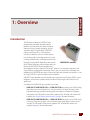
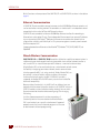
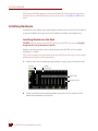
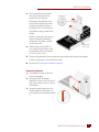
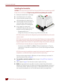
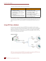
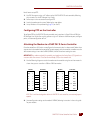
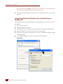
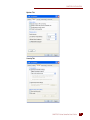
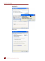
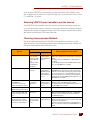
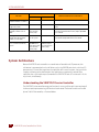
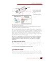
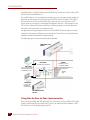
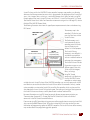
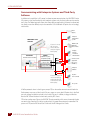
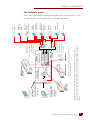
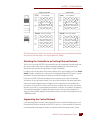
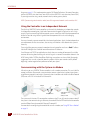
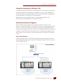
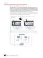
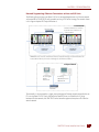
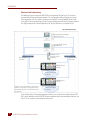
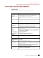
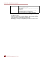
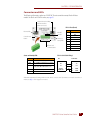
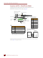
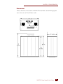
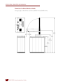
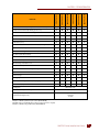

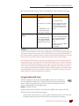
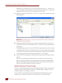
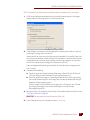
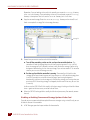
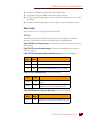
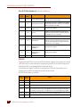
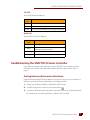
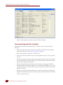
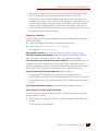
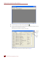
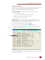
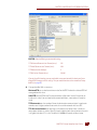
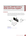
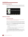
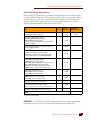
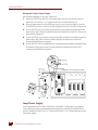
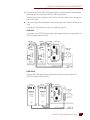


![[ANEXO N°1]](http://vs1.manualzilla.com/store/data/006302967_1-e9ecb6f804c11797b188b7143d3b1bbb-150x150.png)